6.1 This clause deals with snow loads on roofs of buildings. Roofs should be designed for the actual load due to snow or for the imposed loads specified in 3, whichever is more severe.
NOTE — Mountainous regions in northern parts of India are subjected to snow fall. In India, part of Jammu and Kashmir (Baramulla District, Srinagar District, Anantnag District, and Leh and Kargil District); Punjab and Himachal Pradesh (Chamba, Kullu, Kinnaur District, Mandi District, Sirmaur District and Simla District); and Uttarakhand (Dehra Dun District, Tehri Garhwal District, Almora District, Pithoragarh District and Nainital District) experience snow fall of varying depths two or three times in a year.
6.2 Notations
a) (Dimensionless) — Nominal values of the shape coefficients, taking into account snow drifts, sliding snow, etc, with subscripts, if necessary.
b) (metre) — Horizontal dimension with numerical subscripts, if necessary.
c) (metre) — Vertical dimensions with numerical subscripts, if necessary.
d) (degree) — Roof slope.
e) (pascal) — Snow load on ground.
f) (pascal) — Snow load on roofs.
6.3 Snow Load in Roof(s)
6.3.1 The minimum design snow load on a roof area or
any other area above ground which is subjected to snow accumulation is obtained by multiplying the snow load on ground, by the shape coefficient , as applicable to the particular roof area considered, expressed as:
where
s = design snow load on plan area of roof, in Pa;
shape coefficient (see 6.4); and
s _ {\mathrm{o}} = \text {ground snow load, in Pa (1 Pa = 1 N / m^2).}NOTE — Ground snow load at any place depends on the critical combination of the maximum depth of undisturbed aggregate cumulative snow fall and its average density. In due course the characteristic snow load on ground for different regions will be included based on studies. Till such time the users of this code are advised to contact either Snow and Avalanches Study Establishment (Defence Research and Development Organization), Manali (HP) or India Meteorological Department (IMD), Pune in the absence of any specific information for any location.
6.4 Shape Coefficients
6.4.1 General Principles
In perfectly calm weather, falling snow would cover roofs and the ground with a uniform blanket of snow, and the design snow load could be considered as a uniformly distributed load. Truly uniform loading conditions, however, are rare and have usually only been observed in areas that are sheltered on all sides by high trees, buildings, etc. In such a case, the shape coefficient would be equal to unity.
In most regions, snow-falls are accompanied or followed by winds. The winds will redistribute the snow, and on some roofs especially multilevel roofs, the accumulated drift load may reach a multiple of the ground load. Roofs which are sheltered by other buildings, vegetation, etc, may collect more snow load than the ground level. The phenomenon is of the same nature as that illustrated for multilevel roofs in 6.4.2.4.
So far, sufficient data are not available to determine the shape coefficient on a statistical basis. Therefore, a nominal value is given. A representative sample of roofs is shown in 6.4.2. However, in special cases such as strip loading, cleaning of the roof periodically by deliberate heating of the roof, etc, have to be treated separately.
The distribution of snow in the direction parallel to the caves is assumed to be uniform.
6.4.2 Shape Coefficients for Selected Types of Roofs
6.4.2.1
Simple Flat and Monopitch Roofs
Simple Pitched Roofs (Positive Roof Slope)
6.4.2.2
Simple or Multiple Pitched Roofs (Negative Roof Slope)
Two-Span or Multispan Roof
93
For asymmetrical simple pitched roofs, each side of the roof shall be treated as one half of corresponding symmetrical roofs.
PART 6 STRUCTURAL DESIGN — SECTION 1 LOADS, FORCES AND EFFECTS

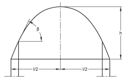
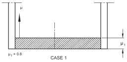
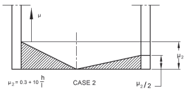
6.4.2.3 Simple curved roofs
THE FOLLOWING CASES 1 AND 2 MUST BE EXAMINED
6.4.2.4 Multilevel roofs
where
due to sliding
due to wind
but is restricted as follows:
with the restriction
where
is in metres
is in kilopascals (kilonewtons per square metre)
is determined from an additional load amounting to 50 percent of the maximum total load on the adjacent slope of the upper root and is distributed linearly as shown in the figure.
- A more extensive formula for is described in Annex L.
- If the coefficient is determined by interpolation between and .
6.4.2.5 Complex multilevel roofs
The load on the upper roof is calculated according to 6.4.2.1.
Restriction:
and , are calculated according to 6.4.2.1, 6.4.2.2 and 6.4.2.4
6.4.2.6 Roofs with local projections and obstructions
is in metres
is in kilopascals (kilonewtons per square metre)
Restrictions:
6.4.3 Shape Coefficients in Areas Exposed to Wind
The shape coefficients given in 6.4.2 and Annex L may be reduced by 15 percent, provided the designer has demonstrated that the following conditions are fulfilled:
a) The building is located in an exposed location such as open level terrain with only scattered buildings, trees or other obstructions so that the roof is exposed to the winds on all sides and is not likely to become shielded in the future by obstructions higher than the roof within a distance from the building equal to ten times the height of the obstruction above the roof level; and
b) The roof does not have any significant projections such as parapet walls which may prevent snow from being blown off the roof.
NOTE — In some areas, winter climate may not be of such a nature as to produce a significant reduction of roof loads from the snow load on the ground. These areas are:
a) Winter calm valleys in the mountains where sometimes layer after layer of snow accumulates on roofs without any appreciable removal of snow by wind; and
b) Areas (that is, high temperature) where the maximum snow load may be the result of single snowstorm, occasionally without appreciable wind removal.
In such areas, the determination of the shape coefficients shall be based on local experience with due regard to the likelihood of wind drifting and sliding.