f) Effects of low temperature (< brittle transition temperature).
19.1.1 For the purpose of design against fatigue, different details (of members and connections) are classified under different fatigue class. The design stress range corresponding to various number of cycles, are given for each fatigue class. The requirements of this Section shall be satisfied with, at each critical location of the structure subjected to cyclic loading, considering relevant number of cycles and magnitudes of stress range expected to be experienced during the life of the structure.
19.2Design
19.2.1 Reference Design Condition
The standard S-N curves for each detail category are given for the following conditions:
a) Detail is located in a redundant load path, wherein local failure at that detail alone will not lead to overall collapse of the structure.
b) Nominal stress history at the local point in the detail is estimated/evaluated by a conventional method without taking into account the local stress concentration effects due to the detail.
c) Load cycles are not highly irregular.
d) Details are accessible for and subject to regular inspection.
e) Structure is exposed to only mildly corrosive environment as in normal atmospheric condition and suitably protected against corrosion (pit depth <1 mm).
f) Structure is not subjected to temperature exceeding 150 °C.
g) Transverse fillet or butt weld connects plates of thickness not greater than 25 mm.
19.2.1.1 Thickness correction factor
The values obtained from the standard S-N curve shall be modified by a capacity reduction factor μr, when plates greater than 25mm in thickness are joined together by transverse fillet or butt welding, given by:
μr=(25/tp)0.25≤1.0
where
tp= actual thickness of the thicker plate being joined, in mm.
No thickness correction is necessary when full
penetration butt weld reinforcements are machined flush and proved free of defect through non-destructive testing.
19.2.1.2 Necessity for fatigue assessment
a) Fatigue assessment is not normally required for building structures except as follows:
Members supporting lifting or rolling loads,
Member subjected to repeated stress cycles from vibrating machinery,
Members subjected to wind induced oscillations of a large number of cycles in life, and
Members subjected to crowd induced oscillations of a large number of cycles in life.
b) No fatigue assessment is necessary, if the following conditions are satisfied.
The highest normal stress range ffmax satisfies:
f
19.2.2 Design Spectrum
19.2.2.1 Stress evaluation
Design stress shall be determined by elastic analysis of the structure to obtain stress resultants and the local
stresses may be obtained by a conventional stress analysis method. The normal and shear stresses shall be determined considering all design actions on the members, but excluding stress concentration due to the geometry of the detail. The stress concentration effect is accounted for in detail category classification (see Table 26). The stress concentration, however, not characteristic of the detail shall be accounted for separately in the stress calculation.
In the fatigue design of trusses made of members with open sections, in which the end connections are not pinned, the stresses due to secondary bending moments shall be taken into account, unless the slenderness ratio (KL/r) , of the member is greater than 40.
In the determination of stress range at the end connections between hollow sections, the effect of connection stiffness and eccentricities may be disregarded, provided,
a) the calculated stress range is multiplied by appropriate factor given in Table 24(a) in the case of circular hollow section connections and Table 24(b) in the case of rectangular hollow section connections.
b) the design throat thickness of fillet welds in the joints is greater than the wall thickness of the connected member.
19.2.2.2 Design stress spectrum
In the case of loading events producing non-uniform stress range cycle, the stress spectrum may be obtained by a rational method, such as ‘rain flow counting’ or an equivalent method.
Table 24(a) Multiplying Factors for Calculated Stress Range (Circular Hollow Sections) (Clause 19.2.2.1)
Sl No.
Type of Connection
Chords
Verticals
Diagonals
(1)
(2)
(3)
19.2.3 Partial Safety Factors
19.2.3.1 Partial safety factor for actions and their effects ( gamma{fft} )
Unless and otherwise the uncertainty in the estimation of the applied actions and their effects demand a higher value, the partial safety factor for loads in the evaluation of stress range in fatigue design shall be taken as 1.0.
19.2.3.2 Partial safety factor for fatigue strength ( gamma{mft} )
Partial safety factor for strength is influenced by consequences of fatigue damage and level of inspection capabilities.
19.2.3.3 Based on consequences of fatigue failure, component details have been classified as given in the Table 25 and the corresponding partial safety factor for fatigue strength shall be used:
a) Failsafe structural component/detail is the one where local failure of one component due to fatigue crack does not result in the failure of the structure due to availability of alternate load path (redundant system).
b) Non-failsafe structural component/detail is the one where local failure of one component leads rapidly to failure of the structure due to its non-redundant nature.
19.4Fatigue Strength
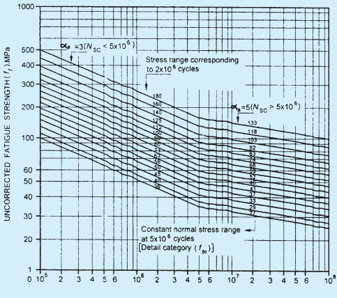
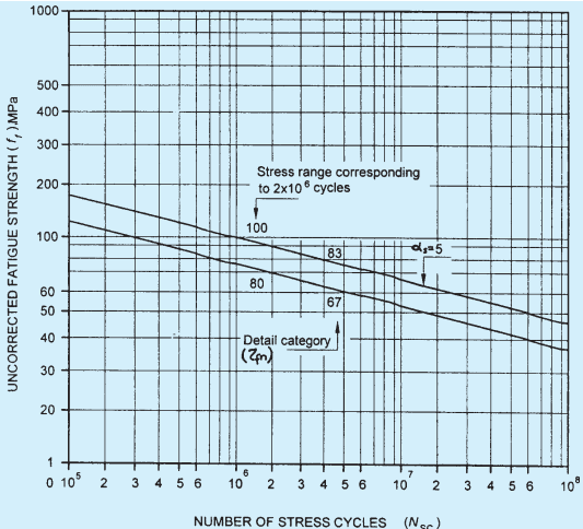
The fatigue strength of the standard detail for the normal or shear fatigue stress range, not corrected for thickness effects discussed in 19.4.1, is given below (see also Fig. 22 and Fig. 23):
a) Normal stress range:
when NSC≤5×10⁶
ff=ffn35×106/N
when5×106≤NSC≤10
ff=ffn55
b) Shear stress:
τf=τfn55
where
fpτf= design normal and shear fatigue stress range of the detail, respectively, for life cycle of NSC , and
ffn,τ
19.5Fatigue Assessment
19.5.1 The design fatigue strength for NSC life cycles (ffd, tfd) may be obtained from the standard fatigue strength for NSC cycles by multiplying with correction factor, mr, for thickness, as mentioned in 19.2.1 and dividing by partial safety factor given in Table 25.
19.5.2 Stress Limitations
19.5.2.1 The maximum (absolute) value of the normal and shear stresses shall never exceed the elastic limit (fy,τy) for the material under cyclic loading.
19.5.2.2 The maximum stress range shall not exceed 1.5f for normal stresses and for the shear stresses under any circumstance.
Section 6 (q) Design Assisted by Testing
fmax
≤
27μr/γmft
The highest shear stress range τfmax satisfies:
τfmax≤67μr/γmft
The total number of actual stress cycles NSC , satisfies:
NSC≤5×10⁶(γmftffeq27μr)3
where
ffeq= equivalent constant amplitude stress range, in MPa, given by:
ffeq=[n∑i=1r5nifi3+]1/3
where
n=i=1∑rni
fi,fj= stress ranges falling above and below the ffh, the stress range corresponding to the detail at 5×10⁶ number of life cycles.
r5 = summation upper limit of all the normal stress ranges (fi) having magnitude lesser than (μrffnγmft) for that detail and the lower limit of all the normal stress ranges ( fj ) having magnitude greater than (μrffnγmft) for that detail.
(4)
(5)
i)
Gap connections
{KtypeNtype
1.5
1.0
1.3
1.5
1.8
1.4
ii)
Overlap connections
{KtypeNtype
1.5
1.0
1.2
1.5
1.65
1.25
Table 24(b) Multiplying Factors for Calculated Stress Range (Rectangular Hollow Sections) (Clause 19.2.2.1)
Periodic inspection, maintenance and accessibility to detail is good
1.00
1.25
ii)
Periodic inspection, maintenance and accessibility to detail is poor
1.15
1.35
SC
8
(2)
×
1
06
/
NSC
×
1
06
/
NSC
fn
=
normalandshearfatiguestrengthofthedetailfor5×
106cycles,forthedetailcategory(seeTable26).
y
1.5fy3
19.5.2.3 Constant stress range
The actual normal and shear stress range f and t at a point of the structure subjected to NSC cycles in life shall satisfy:
f≤ffd=μrff/γ
where
μr= correction factor (see 19.2.2),
γmf = partial safety factor against fatigue failure, given in Table 25, and
ff,τf=normal and shear fatigue strength ranges for the actual life cycle, NSC
19.5.2.4 Variable stress range
Fatigue assessment at any point in a structure, wherein variable stress ranges fi or τi for ni number of cycles are encountered, shall satisfy the following:
a) For normal stress ( f ):
5×10
b) For shear stresses (t):
i=1∑r5n
Where r5 is the summation upper limit of all the normal stress ranges (f) having magnitude lesser than (μrffi for that detail and the lower limit of all the normal stress ranges having magnitude greater than for the detail. In the above summation all normal stress ranges, and shear stress ranges having magnitude less than , and respectively may be disregarded.
Table 26(a) Detail Category Classification, Group 1 Non-Welded Details ( \mathbf { f _ { f n } } ) (Clause 19.3)
Sl No.(1)
Detail Category(2)
Constructional Details
Illustration (see Note)(3)
Description(4)
i)
118
(2)(3)
Rolled and extruded products:a) Plates and flats (1)b) Rolled sections (2)c) Seamless tubes (3)Sharp edges, surface and rolling flaws to be removed by grinding in the direction of applied stress
ii)
103
(4)(5)
(a) Bolted connections:(4) and (5): Stress range calculated on the gross section and on the net sectionUnsupported one-sided cover plate connections shall be avoided or the effect of the eccentricity taken into account in calculating stresses(b) Material with gas-cut or sheared edges with no draglines:(6): All hardened material and visible signs of edge discontinuities to be removed by machining or grinding in the direction of applied stress
iii)
92
Material with machine gas-cut edges with draglines or manual gas-cut material:(7) Corners and visible signs of edge discontinuities to be removed by grinding in the direction of the applied stress
NOTE — The arrow indicates the location and direction of the stresses acting in the basic material for which the stress range is to be calculated on a plane normal to the arrow.
Table 26(b) Detail Category Classification, Group 2 Welded Details — Not in Hollow Sections ( f_{fn} ) (Clause 19.3)
Sl No.
Detail Category
Constructional Details
Illustration (see Note)
Description
i)
92
Welded plate I-section and box girders with continuous longitudinal welds:(8) and (9): Zones of continuous automatic longitudinal fillet or butt welds carried out from both sides and all welds not having un-repaired stop-start positions
ii)
83
(10) (11)
Welded plate I-section and box girders with continuous longitudinal welds:(10) and (11): Zones of continuous automatic butt welds made from one side only with a continuous backing bar and all welds not having un-repaired stop-start positions(12): Zones of continuous longitudinal fillet or butt welds carried out from both sides but containing stop-start positions. For continuous manual longitudinal fillet or butt welds carried out from both sides, use Detail Category 92
iii)
66
Welded plate I-section and box girders with continuous longitudinal welds:(13): Zones of continuous longitudinal welds carried out from one side only, with or without stop-start positions
iv)
59
Intermittent longitudinal welds:(14): Zones of intermittent longitudinal welds
v)
52
Intermittent longitudinal welds:(15): Zones containing cope holes in longitudinally welded T-joints. Cope hole not to be filled with weld
vi)
83
(17)
Transverse butt welds (complete penetration):Weld run-off tabs to be used, subsequently removed and ends of welds ground flush in the direction of stress. Welds to be made from two sides(16): Transverse splices in plates, flats and rolled sections having the weld reinforcement ground flush to plate surface. 100 percent NDT inspection, and weld surface to be free of exposed porosity in the weld metal(17): Plate girders welded as in (16) before assembly(18): Transverse splices as in (16) with reduced or tapered transition with taper ≤ 1:4
PART 6 STRUCTURAL DESIGN — SECTION 6 STEEL
Sl No.
Detail Category
Constructional Details
Illustration (see Note)
Description
(1)
(2)
(3)
(4)
vii)
66
(A5XD)(20)
Transverse butt welds (complete penetration):Welds run-off tabs to be used, subsequently removed and ends of welds ground flush in the direction of stress. Welds to be made from two sides(19): Transverse splices of plates, rolled sections or plate girders(20): Transverse splice of rolled sections or welded plate girders, without cope hole. With cope hole use Detail Category 52, as in (15)(21): Transverse splices in plates or flats being tapered in width or in thickness where the taper is ≤ 1:4
viii)
59
(22)- (23)
Transverse butt welds (complete penetration):Weld run-off tabs to be used, subsequently removed and ends of welds ground flush in the direction of stress. Welds to be made from two sides(22): Transverse splices as in (21) with taper in width or thickness >1:4 but ≤ 1:2.5
ix)
52
Transverse butt welds (complete penetration):(23): Transverse butt-welded splices made on a backing bar. The end of the fillet weld of the backing strip shall stop short by more than 10 mm from the edges of the stressed plate(24): Transverse butt welds as per (23) with taper on width or thickness <1:2.5
x)
37
(25)
Transverse butt welds (complete penetration):(25): Transverse butt welds as in (23) where fillet welds end closer than 10 mm to plate edge
xi)
52
(26)
Cruciform joints with load-carrying welds:(26): Full penetration welds with intermediate plate NDT inspected and free of defects. Maximum misalignment of plates either side of joint to be < 0.15 times the thickness of intermediate plate
xii)
41
(27)
(27) & (28)
(27): Partial penetration or fillet welds with stress range calculated on plate area(28): Partial penetration or fillet welds with stress range calculated on throat area of weld
27
(28)
Table 26(b) — (Concluded)
Sl No.
Detail Category
Constructional Details
Illustration (see Note)
Description
(1)
(2)
(3)
(4)
xiii)
46
(29)(30) & (31)
Overlapped welded joints:(29): Fillet welded lap joint, with welds and overlapping elements having a design capacity greater than the main plate. Stress in the main plate to be calculated on the basis of area shown in the illustration
xiv)
41
(30)
Overlapped weld joints:(30): Fillet welded lap joint, with welds and main plate both having a design capacity greater than the overlapping elements
xv)
33
(31)
(31): Fillet welded lap joint, with main plate and overlapping elements both having a design capacity greater than the weld
xvi)
66
(32)
(33)
[Welded attachments (non-load carrying welds) - Longitudinal welds:(32): Longitudinal fillet welds. Class of detail varies according to the length of the attachment weld as noted(33): Gusset welded to the edge of a plate or beam flange. Smooth transition radius (r), formed by machining or flame cutting plus grinding. Class of detail varies according to r/b ratio as noted
—
1/3 ≤ r/b
59
l ≤ 50mm
—
52
50 < l≤ 100mm
1/6≤r/b <1/3
37
100 mm < l
—
33
—
r/b<1/6
xvii)
59
(34)
Welded attachments:(34): Shear connectors on base material (failure in base material)
xviii)
59
t ≤ 12mm
(35)(36)(37)
Transverse welds:(35): Transverse fillet welds with the end of the weld ≥10 mm from the edge of the plate(36): Vertical stiffeners welded to a beam or plate girder flange or web by continuous or intermittent welds. In the case of webs carrying combined bending and shear design actions, the fatigue strength shall be determined using the stress range of the principal stresses(37): Diaphragms of box girders welded to the flange or web by continuous or intermittent welds
52
t > 12mm
xix)
PART 6 STRUCTURAL DESIGN — SECTION 6 STEEL
Table 26(c) Detail Category Classification, Group 3 Bolts (Clause 19.3)
Sl No.(1)
Detail Category(2)
Constructional Details
Illustration (see Note)(3)
Description(4)
i)
83
(41)
Bolts in shear (8.8/TB Bolting category only):(41): Shear stress range calculated on the minor diameter area of the bolt ( Ac )NOTE – If the shear on the joint is insufficient to cause slip of the joint the shear in the bolt need not be considered in fatigue
ii)
27
(42)
Bolts and threaded rods in tension (tensile stress to be calculated on the tensile stress area, At ): (42): Additional forces due to prying effects shall be taken into account. For tensional bolts, the stress range depends on the connection geometryNOTE – In connections with tensioned bolts, the change in the force in the bolts is often less than the applied force, but this effect is dependent on the geometry of the connection. It is not normally required that any allowance for fatigue be made in calculating the required number of bolts in such connections
(Nsc)
FIG. 22 S-N CURVE FOR NORMAL STRESS
Table 26(d) Detail Category Classification, Group 4 Welded Details – In Hollow Sections ( f_{fn} ) (Clause 19.3)
Sl No.(1)
Detail Category(2)
Constructional Details
Illustration (see Note)(3)
Description(4)
i)
103
(43)
Continuous automatic longitudinal welds:(43): No stop-starts, or as manufactured, proven free to detachable discontinuities.
ii)
66(t≥8 mm)
(44)
Transverse butt welds:(44): Butt-welded end-to-end connection of circular hollow sectionsNOTE — Height of the weld reinforcement less than 10 percent of weld with smooth transition to the plate surface. Welds made in flat position and proven free to detachable discontinuities)(45): Butt-welded end-to-end connection of rectangular hollow sections
52(t<8 mm)
iii)
52(t≥8 mm)
(45)
41(t<8 mm)
iv)
41(t≥8 mm)
(46)
Butt welds to intermediate plate:(46): Circular hollow sections, end-to-end butt-welded with an intermediate plate(47): Rectangular hollow sections, end-to-end butt welded with an intermediate plate
37(t<8 mm)
v)
37(t≥8 mm)
(47)
30(t<8 mm)
vi)
52
(48)
Welded attachments (non-load-carrying):(48): Circular or rectangular hollow section, fillet welded to another section. Section width parallel to stress direction ≤ 100 mm
vii)
33(t<8 mm)
(49)
Fillet welds to intermediate plate(49): Circular hollow sections, end-to-end fillet welded with an intermediate plate(50): Rectangular hollow sections, end-to-end fillet welded with an intermediate plate
29(t<8 mm)
viii)
29(t≥8 mm)
(50)
27(t<8 mm)
NOTE □ The arrow indicates the location and direction of the stresses acting in the basic material for which the stress range is to be calculated on a plane normal to the arrow.
PART 6 STRUCTURAL DESIGN — SECTION 6 STEEL
FIG. 23 S-N CURVE FOR SHEAR STRESS
∑j=r5r
nj
fj5
mft
τ≤τfd=μrτf/γmft
,
obtained from 19.4.
(i=1tor)
6
(μrffn/γmft)3
∑i=1r5nifi3
+
5×10⁶(μrffn/γmft)5∑j=r5rnjfj5≤
1.0
i
τi5
≤
5×
106(μτfn/γmft)5
/
γmff
)
(fj)
(μrffn/γmff)
fi′
τi
0.55μpffn,
0.55μrτfn,
37
tf or tp ≤25mm
(38)
Cover plates in beams and plate girders:(38): End zones of single or multiple welded cover plates, with or without a weld across the end. For a reinforcing plate wider than the flange, an end weld is essential
27
tf or tp >25 mm
xx)
67
Welds loaded in shear:(39): Fillet welds transmitting shear. Stress range to be calculated on weld throat area(40): Stud welded shear connectors (failure in the weld) loaded in shear (the shear stress range to be calculated on the nominal section of the stud)
NOTE — The arrow indicates the location and direction of the stresses acting in the basic material for which the stress range is to be calculated on a plane normal to the arrow.
NOTE – The arrow indicates the location and direction of the stresses acting in the basic material for which the stress range is to be calculated on a plane normal to the arrow.