9.0 The term ‘low strength masonry’ includes fired brickwork laid in clay mud mortar and random rubble; uncoursed, undressed or semi-dressed stone masonry in weak mortars; such as cement sand, lime sand and clay mud. Special features of design and construction for improving earthquake resistance of buildings of low strength masonry are given in 9.1 to 9.6.5.7.
9.1 For the purpose of this clause, the terminology given in 8.1 shall apply.
9.2 General Principles
The general principles given in 9.2.1 to 9.2.5 shall be observed in construction of earthquake resistant buildings.
9.2.1 Lightness
Since the earthquake force is a function of mass, the weight of the building shall be as minimum as possible, consistent with structural safety and functional requirements. Roofs and upper storeys of buildings, in particular, should be designed as light as possible.
9.2.2 Continuity of Construction
9.2.2.1 As far as possible, the parts of the building should be tied together in such a manner that the building acts as one unit.
9.2.2.2 For integral action of building, roof and floor slabs should be continuous throughout as far as possible.
9.2.2.3 Additions and alterations to the structures should be accompanied by the provision of positive measures to establish continuity between the existing and the new construction.
9.2.3 Projecting and Suspended Parts
9.2.3.1 Projecting parts should be avoided as far as
possible. If the projecting parts cannot be avoided, they should be properly reinforced and firmly tied to the main structure, and their design should be in accordance with good practice [6-4(7)].
NOTE — In cases where stability of projecting parts against overturning is achieved by counterweight in the form of wall, slab, etc, the overturning should be checked by increasing the weight of projecting part and decreasing the weight of stabilizing mass simultaneously in accordance with the vertical seismic coefficient specified in 4.4.2 of good practice [6-4(7)].
9.2.3.2 Ceiling plaster shall preferably be avoided. When it is unavoidable, the plaster shall be as thin as possible.
9.2.3.3 Suspended ceiling shall be avoided as far as possible. Where provided they shall be light, adequately framed and secured.
9.2.4 Building Configuration
9.2.4.1 In order to minimise torsion, the building should have a simple rectangular plan and be symmetrical both
PART 6 STRUCTURAL DESIGN — SECTION 4 MASONRY
with respect to mass and rigidity so that the centre of mass and rigidity of the building coincide with each other. It will be desirable to use separate blocks of rectangular shape particularly in Seismic Zone V and Seismic Zone IV.
NOTE — For small buildings, minor asymmetry in plan and elevation may be ignored. Designing such buildings against torsion may be difficult and uncertain.
9.2.5 Fire Safety
Fire frequently follows an earthquake and therefore, buildings shall be constructed to make them fire resistant in accordance with the provisions of Part 4 ‘Fire and Life Safety’ of the Code for fire safety, as relevant.
9.3Special Construction Features
9.3.1 Foundations
9.3.1.1 For the design of foundations, the provisions of Part 6 ‘Structural Design, Section 2 Soils and Foundation’ of the Code in conjunction with 5 of Part
6 ‘Structural Design, Section 1 Loads, Forces and Effects’ of the Code shall generally be followed.
9.3.1.2 The subgrade below the entire area of the building shall preferably be of the same type of the soil. Wherever this is not possible, the buildings should preferably be separated into units and then the units should be located separately.
9.3.1.3 Loose fine sand, soft silt and expansive clays should be avoided. If unavoidable, the following measures may be taken to improve the soil on which the foundation of the building may rest:
a) Sand piling/under-reamed piling/stone columns, etc; and
b) Soil stabilization.
9.3.2 Roofs and Floors
9.3.2.1 Flat roof or floor should not preferably be made of tiles or ordinary bricks supported on steel, timber or reinforced concrete joists, nor they shall be of a type which in the event of an earthquake is likely to be loosened and parts or all of which may fall. If this type of construction cannot be avoided, the joists should be blocked at ends and bridged at intervals such that their spacing is not altered during an earthquake.
9.3.2.1.1 For pitched roofs, corrugated iron or asbestos sheets should be used in preference to country, Allahabad or Mangalore tiles or other loose roofing units. All roofing materials shall be properly tied to the supporting members. Heavy roofing materials shall generally be avoided.
9.3.2.2 Pent roofs
9.3.2.2.1 All roof trusses should be supported on and fixed to timber band, reinforced concrete, or reinforced brick band. The holding down bolts should have adequate size and length as required for earthquake and wind forces.
Where a trussed roof adjoins a masonry gable, the ends of the purlins should be carried on and secured to a plate or bearer which shall be adequately bolted to reinforced concrete or reinforced brick band at the top of gable end masonry.
9.3.2.2.2 At tie level all the trusses and the gable end should be provided with diagonal braces in plan so as to transmit the lateral shear due to earthquake force to the gable walls acting as shear walls.
9.3.2.3 Jack arches
Jack arched roofs or floors, where used should be provided with mild steel ties in all spans along with diagonal braces in plan to ensure diaphragm actions.
9.3.3 Staircases
9.3.3.1 The inter-connection of the stairs with the adjacent floors should be appropriately treated by
providing sliding joints at the stairs to eliminate their bracing effect on the floors. Ladders may be made fixed at one end and freely resting at the other.
9.3.3.2 Built-in staircase
When stairs are built monolithically with floors, they can be protected against damage by providing rigid walls at the stair opening. The walls enclosing the staircase, should extend through the entire height of the stairs and to the building foundations.
9.4 Box Type Construction
This type of construction consists of prefabricated or in-situ masonry walls along both the axes of the building. The walls support vertical loads and also act as shear walls for horizontal loads acting in any direction. All traditional masonry construction falls under this category. In prefabricated construction attention shall be paid to the connection between wall panels so that transfer of shear between them is ensured.
9.5 Categories of Buildings
For the purpose of specifying the earthquake resisting features in masonry and wooden buildings, the buildings have been categorized in four categories B to E based on the seismic zone and the importance of building I, where I – importance factor applicable to the building [see 6.4.2 and Table 6 of good practice [6-4(8)], the classification as given in 8.5 shall be applicable. The building categories are given in Table 14.
9.6Low Strength Masonry Construction
9.6.1 Two types of construction are included herein, namely:
a) Brick construction using weak mortar, and
b) Random rubble and half-dressed stone masonry construction using different mortars such as clay mud, lime-sand and cement sand.
9.6.1.1 These constructions should not be permitted for important buildings and should preferably be avoided for building category D and shall not be used for category E (see Table 14).
9.6.1.2 It will be useful to provide damp-proof course at plinth level to stop the rise of pore water into the superstructure.
9.6.1.3 Precautions should be taken to keep the rain water away from soaking into the wall so that the mortar is not softened due to wetness. An effective way is to take out roof projections beyond the walls by about 500 mm.
9.6.1.4 Use of a water-proof plaster on outside face of walls will enhance the life of the building and maintain its strength at the time of earthquake as well.
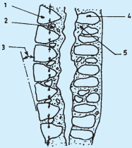
HALF-DRESSED CONICAL STONE 4. RANDOM RUBBLE
SMALL ALIGNMENT 5. MUD OR WEAK LIME
ROTATION OF WYTHE MORTARY
9.6.1.5 Ignoring tensile strength, free standing walls should be checked against overturning under the action of design seismic coefficient, αh, allowing for a factor of safety of 1.5.
9.6.2 Brickwork in Weak Mortars
9.6.2.1 The fired bricks should have a compressive strength not less than 3.5 MPa. Strength of bricks and wall thickness should be selected for the total building height.
9.6.2.2 The mortar should be lime-sand (1:3) or clay mud of good quality. Where horizontal steel is used between courses, cement-sand mortar (1:3) should be used with thickness so as to cover the steel with 6 mm mortar above and below it. Where vertical steel is used, the surrounding brickwork of 1x1 or 121×121 brick size depending on wall thickness should preferably be built using 1:6 cement-sand mortar.
9.6.2.3 The minimum wall thickness shall be one brick in one storey construction, and one brick in top storey and 1½ brick in bottom storeys of up to three storey construction. It should also not be less than 1/16 of the length of wall between two consecutive perpendicular walls.
9.6.2.4 The height of the building shall be restricted to the following, where each storey height shall not exceed 3.0 m :
For Categories B: three storeys with flat roof; and two storeys plus attic for pitched roof.
For Category D: two storeys with flat roof; and one storey plus attic for pitched roof.
9.6.2.5 Special bond in brick walls
For achieving full strength of masonry, the usual bonds specified for masonry should be followed so that the vertical joints are broken properly from course to course. To obtain full bond between perpendicular walls, it is necessary to make a sloping (stepped) joint by making the corners first to a height of 600 mm and then building the wall in between them. Otherwise the toothed joint should be made in both the walls, alternatively in lifts of about 450 mm (see Fig. 20).
9.6.3 Stone Masonry (Random Rubble or Half-Dressed)
9.6.3.1 The construction of stone masonry of random rubble or dressed stone type should generally follow good practice [6-4(14)].
9.6.3.2 The mortar should be cement-sand (1:6), lime sand (1:3) or clay mud of good quality.
9.6.3.3 The wall thickness 't' should not be larger than
450 mm. Preferably it should be about 350 mm, and the stones on the inner and outer wythes should be interlocked with each other.
NOTE — If the two wythes are not interlocked, they tend to delaminate during ground shaking, bulge apart (see Fig. 49) and buckle separately under vertical load leading to complete collapse of the wall and the building.
9.6.3.4 The masonry should preferably be brought to courses at not more than 600 mm lift.
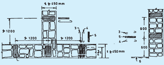
9.6.3.5 ‘Through’ stones of full length equal to wall thickness should be used in every 600 mm lift at not more than 1.2 m apart horizontally. If full length stones are not available, stones in pairs each of about 43 of the wall thickness may be used in place of one full length stone so as to provide an overlap between them (see Fig. 50).
9.6.3.6 In place of ‘through’ stones, ‘bonding elements’ of steel bars 8 mm to 10 mm diameter bent to S-shape or as hooked links may be used with a cover of 25 mm from each face of the wall (see Fig. 50). Alternatively, wood bars of 38 mm × 38 mm cross-section or concrete bars of 50 mm × 50 mm section with an 8 mm diameter rod placed centrally may be used in place of ‘through’ stones. The wood should be well treated with preservative so that it is durable against weathering and insect action.
9.6.3.7 Use of ‘bonding’ elements of adequate length should also be made at corners and junctions of walls to break the vertical joints and provide bonding between perpendicular walls.
9.6.4 Opening in Bearing Walls
9.6.4.1 Door and window openings in walls reduce their lateral load resistance and hence should preferably, be small and more centrally located. The size and position of openings shall be as given in Table 25 and Fig. 21.
9.6.4.2 Openings in any storey shall preferably have their top at the same level so that a continuous band could be provided over them including the lintels throughout the building.
9.6.4.3 Where openings do not comply with the guidelines of Table 25, they should be strengthened by providing reinforced concrete lining as shown in Fig. 22 with 2 high strength deformed steel bars of 8mm diameter.
9.6.4.4 The use of arches to span over the openings is a source of weakness and shall be avoided, otherwise, steel ties should be provided.
Table 25Size and Position of Openings in Bearing Walls (see Fig. 21) (Clauses 9.6.4.1 and 9.6.4.3)
Sl No.
Description
Building Category
B and C
D
(1)
(2)
(3)
(4)
i)
Distance b5 from the inside corner of outside wall, Min, mm
230
600
ii)
Total length of openings, ratio; Max: or shall not exceed:
9.6.5 Seismic Strengthening Arrangements
9.6.5.1 All buildings to be constructed of masonry shall be strengthened by the methods as specified for various categories of buildings, listed in Table 26 and detailed in subsequent clauses. Figure 23 and Fig. 24 show, schematically, the overall strengthening arrangements to be adopted for category D buildings, which consist of horizontal bands of reinforcement at critical levels and vertical reinforcing bars at corners and junctions of walls.
9.6.5.2 Lintel band is a band provided at lintel level on all internal and external longitudinal as well as cross walls except partition walls. The details of the band are given in 9.6.5.5.
c = Roof band and gable band where necessary (see 9.6.5.3 and 9.6.5.4).
d = Vertical steel at corners and junctions of walls (see 9.6.5.7).
f = Bracing in plan at tie level of pitched roofs (see 9.3.2.2.2).
g = Plinth band, where necessary (see 9.6.5.6).
NOTE — For building of category B in two storeys constructed with stone masonry in weak mortar, it will be desirable to provide vertical steel of 10 mm dia in both storeys.
9.6.5.3 Roof band is a band provided immediately below the roof or floors. The details of the band are given in 9.6.5.5. Such a band need not be provided underneath reinforced concrete or reinforced brick slabs resting on bearing walls, provided that the slabs cover the width of end walls fully.
9.6.5.4 Gable band is a band provided at the top of gable masonry below the purlins. The details of the band are given in 9.6.5.5. This band shall be made continuous with the roof band at the eaves level.
9.6.3.8 Height of the stone masonry walls (random rubble or half-dressed) should be restricted as follows, with storey height to be kept 3.0 m maximum, and span of walls between cross walls to be limited to 5.0 m:
FIG. 49 WALL DELAMINATED WITH BUCKLED WYTHES
PART 6 STRUCTURAL DESIGN — SECTION 4 MASONRY
THROUGH STONE 4. HOOKED TIE
PAIR OF OVERLAPPING STONE 5. WOOD PLANK
S-SHAPE TIE 6. FLOOR LEVEL
a) For category B — Two storeys with flat roof or one storey plus attic, if walls are built in lime-sand or mud mortar; and one storey higher if walls are built in cement-sand 1:6 mortar.
b) For categories C and D — Two storeys with flat roof or two storeys plus attic for pitched roof, if walls are built in 1:6 cement mortar; and one storey with flat roof or one storey plus attic, if walls are built in lime-sand or mud mortar, respectively.
9.6.3.9 If walls longer than 5 m are needed, buttresses may be used at intermediate points not farther apart than 4.0 m. The size of the buttress be kept of uniform thickness. Top width should be equal to the thickness of main wall, t, and the base width equal to one sixth of wall height.
(b1+b2+b3)/l1
(b6+b7)/l2
a) one storeyed building
0.46
0.42
b) 2 and 3 storeyed building
0.37
0.33
iii)
Pier width between consecutive openings, b4 , mm
450
560
iv)
Vertical distance between two openings one above the other, h3 , Min, mm
600
600
v)
Width of opening of ventilator, b8 , Max, mm
750
750
9.6.5.5 Details of band
9.6.5.5.1 Reinforced band
The band should be made of reinforced concrete of grade not leaner than M15 or reinforced brickwork in cement mortar not leaner than 1:3. The bands should be of full width of the wall, not less than 75 mm in depth and should be reinforced with 2 high strength deformed steel bars of 8 mm diameter and held in position by 6 mm diameter bar links, installed at 150 mm apart as shown in Fig. 25.
1 In coastal areas, the concrete grade shall be of grade in accordance with Part 6 'Structural Design, Section 5 Concrete' of the Code and the filling mortar of 1:3 ratio (cement-sand) with water proofing admixture.
2 In case of reinforced brickwork, the thickness of joints containing steel bars should be increased to 20mm so as to have a minimum mortar cover of 6mm around the bar. In bands of reinforced brickwork, the area of steel provided should be equal to that specified above for reinforced concrete bands.
3 For full integrity of walls at corners and junctions of walls and effective horizontal bending resistance of bands, continuity of reinforcement is essential. The details as shown in Fig. 25 are recommended.
9.6.5.5.2 Wooden band
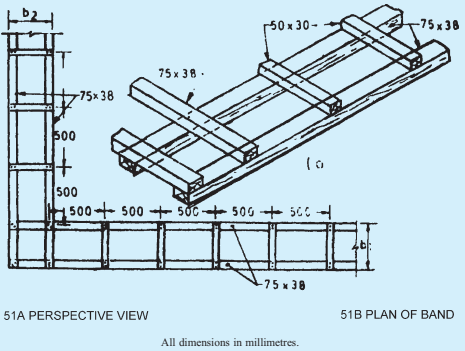
As an alternative to reinforced band, the lintel band could be provided using wood beams in one or two parallel pieces with cross elements as shown in Fig. 51.
FIG. 51 WOODEN BAND FOR LOW-STRENGTH MASONRY BUILDINGS
PART 6 STRUCTURAL DESIGN — SECTION 4 MASONRY
9.6.5.6 Plinth band is a band provided at plinth level of walls on top of the foundation wall. This is to be provided where strip footings of masonry (other than reinforced concrete or reinforced masonry) are used and the soil is either soft or uneven in its properties as frequently happens in hill tracts. Where used, its section may be kept same as in 9.6.5.5.1. This band serves as damp proof course as well.
9.6.5.7 Vertical reinforcement
Vertical steel at corners and junctions of walls which are up to 350 mm thick should be provided as specified in Table 27. For walls thicker than 350 mm, the area of the bars should be proportionately increased.
9.6.5.7.1 The vertical reinforcement should be properly embedded in the plinth masonry of foundations and roof slab or roof band so as to develop its tensile strength in bond. It should pass through the lintel bands and floor slabs or floor level bands in all storeys. Bars in different storeys may be welded or suitably lapped.
1 Typical details of providing vertical steel in brickwork at corners and T-junctions are shown in Fig. 26.
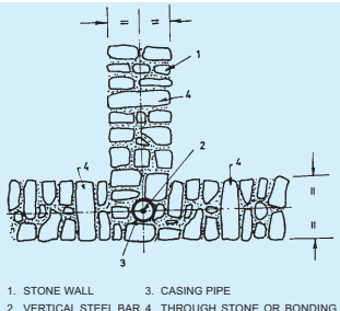
2 For providing vertical bar in stone masonry, use of a casing pipe is recommended around which masonry be built to height of 600 mm (see Fig. 52). The pipe is kept loose by rotating it during masonry construction. It is then raised and the cavity below is filled with M15 (or 1:2:4) grade of concrete mix and rodded to compact it.
Diameter of HSD Single Bar; in mm, at Each Critical Section for
Category B (4)
Category C (5)
Category D (6)
(1)
(2)
(3)
i)
One
—
Nil
Nil
10
ii)
Two
a)
Top
Nil
10
10
b)
Bottom
Nil
10
12
iii)
Three
a)
Top
10
10
10
b)
Middle
10
10
12
c)
Bottom
12
12
12
FIG. 52 TYPICAL CONSTRUCTION DETAIL FOR INSTALLING VERTICAL STEEL BAR IN RANDOM RUBBLE STONE MASONRY
1 The diameters given above are for high strength deformed bars with yield strength 415MPa. For mild-steel plain bars, use equivalent diameters.
2 The vertical bars should be covered with concrete of M15 grade or with mortar 1:3 (cement-sand) in suitably created pockets around the bars (see Fig. 26 and Fig. 52). This will ensure their safety from corrosion and good bond with masonry.
3 For category B two storey stone masonry buildings, see Note under Table 25.
VERTICAL STEEL BAR 4. THROUGH STONE OR BONDING ELEMENT