16.1.1 This Section deals with the design and detailing requirements for joints between members. Connection elements consist of components such as cleats, gusset plates, brackets, connecting plates and connectors such as rivets, bolts, pins, and welds. The connections in a structure shall be designed so as to be consistent with the assumptions made in the analysis of the structure and comply with the requirements specified in this
For members with sway buckling mode, the equivalent uniform moment factor Cmy=Cmz=0.9.
Cmy,Cmz,CmMLT shall be obtained according to the bending moment diagram between the relevant braced points
Table 18Equivalent Uniform Moment Factor (Clause 9.3.2.2)
Bending Moment Diagram
Range
Cmy,Cmz,Cm
Moment factor
Bending axis
Points braced in direction
Cmy
z-z
y-y
Cmz
y-y
z-z
section. Connections shall be capable of transmitting the calculated design actions.
16.1.2 Where members are connected to the surface of a web or the flange of a section, the ability of the web or the flange to transfer the applied forces locally should be checked and where necessary, local stiffening provided.
16.1.3 Ease of fabrication and erection should be considered in the design of connections. Attention should be paid to clearances necessary for field erection, tolerances, tightening of fasteners, welding procedures, subsequent inspection, surface treatment and maintenance.
16.1.4 The ductility of steel assists the distribution of forces generated within a joint. Effects of residual stresses and stresses due to tightening of fasteners and normal tolerances of fit-up need not therefore be considered in connection design, provided ductile behaviour is ensured.
16.1.5 In general, use of different forms of fasteners to transfer the same force shall be avoided. However, when different forms of fasteners are used to carry a
shear load or when welding and fasteners are combined, then one form of fastener shall be normally designed to carry the total load. Nevertheless, fully tensioned friction grip bolts may be designed to share the load with welding, provided the bolts are fully tightened to develop necessary pretension after welding.
16.1.6 The partial safety factor in the evaluation of design strength of connections shall be taken as given in Table 5.
16.2Location Details of Fasteners
16.2.1 Clearances for Holes for Fasteners
Bolts may be located in standard size, over size, short slotted or long slotted hole, as follows.
a) Standard clearance hole — Except where fitted bolts, bolts in low-clearance or oversize holes are specified, the diameter of standard clearance holes for fasteners shall be as given in Table 19.
b) Oversize hole — Holes of size larger than the standard clearance holes, as given in Table 19 may be used in slip resistant connections and
PART 6 STRUCTURAL DESIGN — SECTION 6 STEEL
hold down bolted connections, only where specified, provided the oversize
c) Holes in the outer ply is covered by a cover plate of sufficiently large size and thickness and having a hole not larger than the standard clearance hole (and hardened washer in slip resistant connections).
d) Short and long slots — Slotted holes of size larger than the standard clearance hole, as given in Table 19 may be used in slip resistant connections and hold down bolted connections, only where specified, provided the oversize holes in the outer ply is covered by a cover plate of sufficiently large size and thickness and having a hole of size not larger than the standard clearance hole (and hardened washer in slip resistant connection).
Table 19 Clearances for Fastener Holes(Clause 16.2.1)
Sl No.
Nominal Size of Fastener, d mm
Size of the Hole = Nominal Diameter of the Fastener + Clearances mm
Standard Clearance in Diameter and Width of Slot
Over Size Clearance in Diameter
Clearance in the Length of the Slot
Short Slot (5)
Long Slot (6)
(1)
(2)
(3)
(4)
i)
12-14
1.0
3.0
4.0
2.5 d
ii)
16-22
2.0
4.0
6.0
2.5 d
iii)
24
2.0
6.0
8.0
2.5 d
iv)
Larger than 24
3.0
8.0
10.0
2.5 d
16.2.2 Minimum Spacing
The distance between centres of fasteners shall not be less than 2.5 times the nominal diameter of the fastener.
16.2.3 Maximum Spacing
16.2.3.1 The distance between the centres of any two adjacent fasteners shall not exceed 32t or 300 mm, whichever is less, where t is the thickness of the thinner plate.
16.2.3.2 The distance between the centres of two adjacent fasteners (pitch) in a line lying in the direction of stress, shall not exceed 16t or 200mm, whichever is less, in tension members and 12t or 200mm, whichever is less, in compression members; where t is the thickness of the thinner plate. In the case of compression members wherein forces are transferred through butting faces, this distance shall not exceed 4.5 times the diameter of the fasteners for a distance equal to 1.5 times the width of the member from the butting faces.
16.2.3.3 The distance between the centres of any two consecutive fasteners in a line adjacent and parallel to an edge of an outside plate shall not exceed 100 mm plus 4t or 200 mm, whichever is less, in compression and tension members; where t is the thickness of the thinner outside plate.
16.2.4 Edge and End Distances
16.2.4.1 The edge distance is the distance at right angles to the direction of stress from the centre of a hole to the adjacent edge. The end distance is the distance in the direction of stress from the centre of a hole to the end of the element.
In slotted holes, the edge and end distances should be measured from the edge or end of the material to the centre of its end radius or the centre line of the slot, whichever is smaller. In oversize holes, the edge and end distances should be taken as the distance from the relevant edge/end plus half the diameter of the standard clearance hole corresponding to the fastener, less the nominal diameter of the oversize hole.
16.2.4.2 The minimum edge and end distances from the centre of any hole to the nearest edge of a plate shall not be less than 1.7 times the hole diameter in case of sheared or hand-flame cut edges; and 1.5 times the hole diameter in case of rolled, machine-flame cut, sawn and planed edges.
16.2.4.3 The maximum edge distance to the nearest line of fasteners from an edge of any un-stiffened part should not exceed 12tε , where ε=(250/fy and t is the thickness of the thinner outer plate. This would not apply to fasteners interconnecting the components of back to back tension members. Where the members are exposed to corrosive influences, the maximum edge distance shall not exceed 40 mm plus 4t, where t is the thickness of thinner connected plate.
16.2.5 Tacking Fasteners
16.2.5.1 In case of members covered under 16.2.4.3, when the maximum distance between centres of two adjacent fasteners as specified in 16.2.4.3 is exceeded, tacking fasteners not subjected to calculated stress shall be used.
16.2.5.2 Tacking fasteners shall have spacing in a line not exceeding 32 times the thickness of the thinner outside plate or 300 mm, whichever is less. Where the plates are exposed to the weather, the spacing in line shall not exceed 16 times the thickness of the thinner
outside plate or 200 mm, whichever is less. In both cases, the distance between the lines of fasteners shall not be greater than the respective pitches.
16.2.5.3 All the requirements specified in 16.2.5.2 shall generally apply to compression members, subject to the stipulations in Section 6(g) affecting the design and construction of compression members.
16.2.5.4 In tension members [see Section 6(f)] composed of two flats, angles, channels or tees in contact back to back or separated back to back by a distance not exceeding the aggregate thickness of the connected parts, tacking fasteners with solid distance pieces shall be provided at a spacing in line not exceeding 1 000 mm.
16.2.5.5 For compression members covered in Section 6(g), tacking fasteners in a line shall be spaced at a distance not exceeding 600 mm.
16.2.6 Countersunk Heads
For countersunk heads, one-half of the depth of the countersinking shall be neglected in calculating the length of the fastener in bearing in accordance with 16.3.3. For fasteners in tension having countersunk heads, the tensile strength shall be reduced by 33.3 percent. No reduction is required to be made in shear strength calculations.
16.3Bearing Type Bolts
16.3.1 Effective Areas of Bolts
16.3.1.1 Since threads can occur in the shear plane, the area Ae for resisting shear should normally be taken as the net tensile stress area, An of the bolts. For bolts where the net tensile stress area is not defined, An shall be taken as the area at the root of the threads.
16.3.1.2 Where it can be shown that the threads do not occur in the shear plane, Ae may be taken as the cross-section area, As at the shank.
16.3.1.3 In the calculation of thread length, allowance should be made for tolerance and thread run off.
16.3.2 A bolt subjected to a factored shear force (Vsb) shall satisfy the condition
Vsb≤Vdb
where Vdb is the design strength of the bolt, taken as the smaller of the value as governed by shear, Vdsb (see 16.3.3) and bearing, V (see 16.3.4).
16.3.3 Shear Capacity of Bolt
The design strength of the bolt, Vdsb as governed by shear strength is given by:
Vdsb=
16.3.4 Bearing Capacity of the Bolt
The design bearing strength of a bolt on any plate, Vdpb as governed by bearing is given by:
Vdpb=
16.3.5 Tension Capacity
A bolt subjected to a factored tensile force, Tb shall satisfy,
Tb≤T
16.3.6 Bolt Subjected to Combined Shear and Tension
A bolt required to resist both design shear force (Vsd) and design tensile force (Tb) at the same time shall satisfy,
16.4Friction Grip Type Bolting
16.4.1 In friction grip type bolting, initial pretension in bolt (usually high strength) develops clamping force at the interfaces of elements being joined. The frictional resistance to slip between the plate surfaces subjected to clamping force opposes slip due to externally applied shear. Friction grip type bolts and nuts shall conform to the accepted standard [6-6(37)]. Their installation procedures shall conform to good practice [6-6(15)].
16.4.2 Where slip between bolted plates cannot be tolerated at working loads/strength limit states loads (slip critical connections), the requirements of 16.4.3 shall be satisfied at service and strength limit states loads, respectively. However, the requirements of 16.4.4 shall be satisfied by all connections at the strength limit states.
16.4.3 Slip Resistance
Design for friction type bolting, where slip resistance is required at factored design force Vsf , shall satisfy the following:
Vsf≤Vdsf
where
Vdsf=Vnsf/γmf
Vnsf= nominal shear capacity of a bolt as governed by slip for friction type connection, calculated as follows:
Vnsf=μfneK
where
μf= coefficient of friction (slip factor) as specified in Table 20 (μf≤0.55);
ne = number of effective interfaces offering frictional resistance to slip;
Kh=1.0 for fasteners in clearance holes,
= 0.85 for fasteners in oversized and short slotted holes and for fasteners in long slotted holes loaded perpendicular to the slot,
= 0.7 for fasteners in long slotted holes loaded parallel to the slot;
γmf=1.10 (if slip resistance is designed at service load),
= 1.25 (if slip resistance is designed at ultimate load);
Fo=minimum bolt tension (proof load) at installation and may be taken as Anbfo,
Anb= net area of the bolt at threads, and
fo= proof stress (=0.70fub)
NOTE — Vnsf may be evaluated at a service load or ultimate load using appropriate partial safety factors, depending upon whether slip resistance is required at service load or ultimate load.
Table 20Typical Average Values for Coefficient of Friction ( \mu_{f} ) (Clause 16.4.3)
Sl No.
Treatment of Surface
Coefficient of Friction
(1)
(2)
μf(3)
i)
Surfaces not treated
0.20
ii)
Surfaces blasted with short or grit with any loose rust removed, no pitting
0.50
iii)
Surfaces blasted with shot or grit and hot-dip galvanized
0.10
iv)
Surfaces blasted with shot or grit and spray-metallized with zinc (thickness 50-70 μm)
0.25
v)
Surfaces blasted with shot or grit and painted with ethyl zinc silicate coat (thickness 30-60 μm)
0.30
vi)
Sand blasted surface, after light rusting
0.52
vii)
Surfaces blasted with shot or grit and painted with ethyl zinc silicate coat (thickness 60-80 μm)
0.30
viii)
Surfaces blasted with shot or grit and painted with alkali zinc silicate coat (thickness 60-80 μm)
0.30
ix)
Surface blasted with shot or grit and spray metallized with aluminium (thickness >50 μm)
0.50
x)
Clean mill scale
0.33
xi)
Sand blasted surface
0.48
xii)
Red lead painted surface
0.1
16.4.3.1 Long joints
The provision for the long joints in 16.3.3.1 shall apply to friction grip connections also.
16.4.4 Capacity after Slipping
When friction type bolts are designed not to slip only under service loads, the design capacity at ultimate load
PART 6 STRUCTURAL DESIGN — SECTION 6 STEEL
may be calculated as per bearing type connection (see 16.3.2 and 16.3.3).
NOTE — The block shear resistance of the edge distance due to bearing force may be checked as given in 12.4.
16.4.5 Tension Resistance
A friction bolt subjected to a factored tension force (Tf) shall satisfy:
∣Tf≤T
16.4.6 Combined Shear and Tension
Bolts in a connection for which slip in the serviceability limit state shall be limited, which are subjected to a tension force, T, and shear force, V, shall satisfy:
16.5Welds and Welding
16.5.1 General
Requirements of welds and welding shall conform to the accepted standards [6-6(39)], as appropriate.
16.5.1.1 End returns
Fillet welds terminating at the ends or sides of parts should be returned continuously around the corners for a distance of not less than twice the size of the weld, unless it is impractical to do so. This is particularly important on the tension end of parts carrying bending loads.
16.5.1.2 Lap joint
In the case of lap joints, the minimum lap should not be less than four times the thickness of the thinner part joined or 40 mm, whichever is more. Single end fillet should be used only when lapped parts are restrained from openings. When end of an element is connected only by parallel longitudinal fillet welds, the length of the weld along either edge should not be less than the transverse spacing between longitudinal welds.
16.5.1.3 A single fillet weld should not be subjected to moment about the longitudinal axis of the weld.
16.5.2 Size of Weld
16.5.2.1 The size of normal fillets shall be taken as the minimum weld leg size. For deep penetration welds, where the depth of penetration beyond the root run is a minimum of 2.4 mm, the size of the fillet should be taken as the minimum leg size plus 2.4 mm.
16.5.2.2 For fillet welds made by semi-automatic or automatic processes, where the depth of penetration is considerably in excess of 2.4mm, the size shall be taken considering actual depth of penetration subject to agreement between the purchaser and the contractor.
16.5.2.3 The size of fillet welds shall not be less than 3mm. The minimum size of the first run or of a single run fillet weld shall be as given in Table 21, to avoid the risk of cracking in the absence of preheating.
16.5.2.4 The size of butt weld shall be specified by the effective throat thickness.
16.5.3 Effective Throat Thickness
16.5.3.1 The effective throat thickness of a fillet weld shall not be less than 3 mm and shall generally not exceed 0.7t, or 1.0t under special circumstances, where t is the thickness of the thinner plate of elements being welded.
16.5.3.2 For the purpose of stress calculation in fillet welds joining faces inclined to each other, the effective throat thickness shall be taken as K times the fillet size, where K is a constant, depending upon the angle between fusion faces, as given in Table 22.
Table 21Minimum Size of First Run or of a Single Run Fillet Weld (Clause 16.5.2.3)
Sl No.
Thickness of Thicker Part mm
Minimum Size mm
Over
Up to and Including
(1)
(2)
(3)
(4)
i)
-
10
3
ii)
10
20
5
iii)
20
32
6
iv)
32
50
8 of first run10 for minimum size of weld
NOTES
1 When the minimum size of the fillet weld given in the table is greater than the thickness of the thinner part, the minimum size of the weld should be equal to the thickness of the thinner part. The thicker part shall be adequately preheated to prevent cracking of the weld.
2 Where the thicker part is more than 50mm thick, special precautions like preheating should be taken.
Table 22Values of K for Different Angles Between Fusion Faces
Angle
16.5.4 Effective Length or Area of Weld
16.5.4.1 The effective length of fillet weld shall be taken as only that length which is of the specified size and required throat thickness. In practice the actual length of weld is made of the effective length shown in drawing plus two times the weld size, but not less than four times the size of the weld.
16.5.4.2 The effective length of butt weld shall be taken as the length of the continuous full size weld, but not less than four times the size of the weld.
16.5.4.3 The effective area of a plug weld shall be considered as the nominal area of the hole in the plane of the faying surface. These welds shall not be designed to carry stresses.
16.5.4.4 If the maximum length lj of the side welds transferring shear along its length exceeds 150 times the throat size of the weld, tt, the reduction in weld strength as per the long joint (see 16.5.7.3) should be considered. For flange to web connection, where the welds are loaded for the full length, the above limitation would not apply.
16.5.5 Intermittent Welds
16.5.5.1 Unless otherwise specified, the intermittent fillet welding shall have an effective length of not less than four times the weld size, with a minimum of 40 mm.
16.5.5.2 The clear spacing between the effective lengths of intermittent fillet weld shall not exceed 12 and 16 times the thickness of thinner plate joined, for compression and tension joint, respectively, and in no case be more than 200 mm.
16.5.5.3 Unless otherwise specified, the intermittent butt weld shall have an effective length of not less than four times the weld size and the longitudinal space between the effective length of welds shall not be more than 16 times the thickness of the thinner part joined. The intermittent welds shall not be used in positions subject to dynamic, repetitive and alternating stresses.
16.5.6 Weld Types and Quality
For the purpose of this code, weld shall be fillet, butt, slot or plug or compound welds. Welding electrodes shall conform to the accepted standard [6-6(18)].
16.5.7 Design Stresses in Welds
16.5.7.1 Shop welds
16.5.7.1.1 Fillet welds
Design strength of a fillet weld, fwd shall be based on its throat area and shall be given by:
fwd=
16.5.9 Stresses Due to Individual Forces
When subjected to either compressive or tensile or shear force alone, the stress in the weld is given by:
faorq=ttl
16.5.10 Combination of Stresses
16.5.10.1 Fillet welds
16.5.10.1.1 When subjected to a combination of normal and shear stress, the equivalent stress fe shall satisfy the following:
fe=
16.6Design of Connections
Each element in a connection shall be designed so that the structure is capable of resisting the design actions. Connections and adjacent regions of the members shall be designed by distributing the design action effects such that the following requirements are satisfied:
a) Design action effects distributed to various elements shall be in equilibrium with the design action effects on the connection,
b) Required deformations in the elements of the connections are within their deformations capacities,
c) All elements in the connections and the adjacent areas of members shall be capable of resisting the design action effects acting on them, and
d) Connection elements shall remain stable under the design action effects and deformations.
16.6.1 Connections can be classified as rigid, semi-rigid and flexible for the purpose of analysis and design as per the recommendation in Annex E. Connections with sufficient rotational stiffness may be considered as rigid. Examples of rigid connections include flush end-plate connection and extended end-plate connections. Connections with negligible rotational stiffness may be considered as flexible (pinned). Examples of flexible connections include single and double web angle connections and header plate connections. Where a connection cannot be classified as either rigid or flexible, it shall be assumed to be semi-rigid. Examples of semi-rigid connections include top and seat angle connection and top and seat angle with single/double web angles.
16.6.2 Design shall be on the basis of any rational method supported by experimental evidence. Residual stresses due to installation of bolts or welding normally need not be considered in statically loaded structures. Connections in cyclically loaded structures shall be designed considering fatigue as given in Section 6(p). For earthquake load combinations, the connections shall be designed to withstand the calculated design action effects and exhibit required ductility as specified in Section 6(n).
16.6.3 Beam and column splice shall be designed in accordance with the recommendation given in F-2 and F-3.
16.7Minimum Design Action on Connection
Connections carrying design action effects, except for lacing connections, connections of sag rods, purlins and girts, shall be designed to transmit the greater of,
a) the design action in the member; and
b) the minimum design action effects expressed either as the value or the factor times the member design capacity for the minimum size of member required by the strength limit state, specified as follows:
PART 6 STRUCTURAL DESIGN — SECTION 6 STEEL
Connections in rigid construction — A bending moment of at least 0.5 times the member design moment capacity.
Connections to beam in simple construction — A shear force of at least 0.15 times the member design shear capacity or 40 kN, whichever is lesser.
Connections at the ends of tensile or compression member — A force of at least 0.3 times the member design capacity.
Splices in members subjected to axial tension — A force of at least 0.3 times the member design capacity in tension.
Splices in members subjected to axial compression — For ends prepared for full contact in accordance with 23.7.1, it shall be permissible to carry compressive actions by bearing on contact surfaces. When members are prepared for full contact to bear at splices, there shall be sufficient fasteners to hold all parts securely in place. The fasteners shall be sufficient to transmit a force of at least 0.15 times the member design capacity in axial compression.
When members are not prepared for full contact, the splice material and its fasteners shall be arranged to hold all parts in line and shall be designed to transmit a force of at least 0.3 times the member design capacity in axial compression.
In addition, splices located between points of effective lateral support shall be designed for the design axial force, Pd plus a design bending moment, not less than the design bending moment Md=Pdls/1000 where, ls is the distance between points of effective lateral support.
Splices in flexural members — A bending moment of 0.3 times the member design capacity in bending. This provision shall not apply to splices designed to transmit shear force only.
A splice subjected to a shear force only shall be designed to transmit the design shear force together with any bending moment resulting from the eccentricity of the force with respect to the centroid of the group.
Splices in members subject to combined actions – A splice in a member subject to a combination of design axial tension or design axial compression and design bending moment shall satisfy
requirements in (4), (5) and (6), simultaneously.
For earthquake load combinations, the design action effects specified in this section may need to be increased to meet the required behaviour of the steel frame and shall comply with Section 6(n).
16.8Intersections
Members or components meeting at a joint shall be arranged to transfer the design actions between the parts, wherever practicable, with their centroidal axes meeting at a point. Where there is eccentricity at joints, the members and components shall be designed for the design bending moments which result due to eccentricity.
The disposition of fillet welds to balance the design actions about the centroidal axis or axes for end connections of single angle, double angle and similar type members is not required for statically loaded members but is required for members, connection components subject to fatigue loading.
Eccentricity between the centroidal axes of angle members and the gauge lines for their bolted end connections may be neglected in statically loaded members, but shall be considered in members and connection components subject to fatigue loading.
16.9 Choice of Fasteners
Where slip in the serviceability limit state is to be avoided in a connection, high-strength bolts in a friction-type joint, fitted bolts or welds shall be used.
Where a joint is subjected to impact or vibration, either high strength bolts in a friction type joint or ordinary bolts with locking devices or welds shall be used.
16.10 Connection Components
Connection components (cleats, gusset plates, brackets and the like) other than connectors, shall have their capacities assessed using the provisions of Sections 6(e), 6(f), 6(g), 6(h) and 6(i), as applicable.
16.11Analysis of a Bolt/Weld Group
16.11.1 Bolt/Weld Group Subject to In-plane Loading
16.11.1.1 General method of analysis
The design force in a bolt/weld or design force per unit length in a bolt/weld group subject to in-plane loading shall be determined in accordance with the following:
a) The connection plates shall be considered to be rigid and to rotate relative to each other about a point known as the instantaneous centre of rotation of the group.
b) In the case of a group subject to a pure couple only, the instantaneous centre of rotation coincides with the group centroid. In the case of in-plane shear force applied at the group centroid, the instantaneous centre of the rotation is at infinity and the design force is uniformly distributed throughout the group. In all other cases, either the results of independent analyses for a pure couple alone and for an in-plane shear force applied at the group centroid shall be superposed, or a recognized method of analysis shall be used.
c) The design force in a bolt or design force per unit length at any point in the group shall be assumed to act at right angles to the radius from that point to the instantaneous centre, and shall be taken as proportional to that radius.
16.11.2 Bolt/Weld Group Subject to Out-of-Plane Loading
16.11.2.1 General method of analysis
The design force of a bolt in bolt group or design force per unit length in the fillet weld group subject to out-of-plane loading shall be determined in accordance with the following:
a) Design force in the bolts or per unit length in the fillet weld group resulting from any shear force or axial force shall be considered to be equally shared by all bolts in the group or uniformly distributed over the length of the fillet weld group.
b) Design force resulting from a design bending moment shall be considered to vary linearly with distance from the relevant centroidal axes. The following shall also be considered:
In bearing type of bolt group plates in the compression side of the neutral axis and only bolts in the tension side of the neutral axis may be considered for calculating the neutral axis and second moment of area.
In the friction grip bolt group, only the bolts shall be considered in the calculation of neutral axis and second moment of area.
The fillet weld group shall be considered in isolation from the connected element; for the calculation of centroid and second moment of the weld length.
16.11.2.2 Alternative analysis
The design force per unit length in a fillet weld/bolt group may alternatively be determined by considering the fillet weld group as an extension of the connected
member and distributing the design forces among the welds of the fillet weld group so as to satisfy equilibrium between the fillet weld group and the elements of the connected member.
16.11.3 Bolt/Weld Group Subject to In-Plane and Out-of-Plane Loading
16.11.3.1 General method of analysis
The design force in a bolt or per unit length of the weld shall be determined by the superposition of analysis for in-plane and out-of-plane cases discussed in 16.11.1 and 16.11.2.
16.11.3.2 Alternative analysis
The design force in a bolt or per unit length in the fillet weld group may alternatively be determined by considering the fillet weld group as an extension of the connected member and proportioning the design force per bolt or unit length in the weld group to satisfy equilibrium between the bolt/weld group and the elements of the connected member.
Force calculated in the most stressed bolt or highest force per unit length of the weld shall satisfy the strength requirements of 16.3, 16.4 or 16.5, as appropriate.
16.12Lug Angles
16.12.1 Lug angles connecting outstanding leg of a channel-shaped member shall, as far as possible, be disposed symmetrically with respect to the section of the member.
16.12.2 In the case of angle members, the lug angles and their connections to the gusset or other supporting member shall be capable of developing a strength not less than 20 percent in excess of the force in the outstanding leg of the member, and the attachment of the lug angle to the main angle shall be capable of developing a strength not less than 40 percent in excess of the force in the outstanding leg of the angle.
16.12.3 In the case of channel members and the like, the lug angles and their connection to the gusset or other supporting member shall be capable of developing a strength of not less than 10 percent in excess of the force not accounted for by the direct connection of the member, and the attachment of the lug angles to the member shall be capable of developing 20 percent in excess of that force.
16.12.4 In no case shall fewer than two bolts, rivets or equivalent welds be used for attaching the lug angle to the gusset or other supporting member.
16.12.5 The effective connection of the lug angle shall, as far as possible terminate at the end of the member connected, and the fastening of the lug angle to the main member shall preferably start in advance of the
PART 6 STRUCTURAL DESIGN — SECTION 6 STEEL
direct connection of the member to the gusset or other supporting member.
16.12.6 Where lug angles are used to connect an angle member, the whole area of the member shall be taken as effective notwithstanding the requirements of Section 6(f).
Section 6 (m) Working Stress Design
Uniform Loading
Concentrated Load
(1)
(2)
(3)
(4)
-1 ≤ ψ ≤ 1
0.6 + 0.4 ψ ≥ 0.4
0 ≤ αs ≤ 1
-1 ≤ ψ ≤ 1
0.2 + 0.8 αs ≥ 0.4
0.2 + 0.8 αs ≥ 0.4
-1 ≤ αs ≤ 0
0 ≤ ψ ≤ 1
0.1 - 0.8 αs ≥ 0.4
-0.8 αs ≥ 0.4
-1 ≤ ψ ≤ 0
0.1(1-ψ) -0.8 αs ≥ 0.4
0.2(1-ψ) -0.8 αs ≥ 0.4
0 ≤ αh ≤ 1
-1 ≤ ψ ≤ 1
0.95 - 0.05 αh
0.90 + 0.10 αh
-1 ≤ αh ≤ 0
0 ≤ ψ ≤ 1
0.95 + 0.05 αh
0.90 + 0.10 αh
-1 ≤ ψ ≤ 0
0.95 + 0.05 αh (1+2 ψ)
0.90 + 0.1αh (1+2 ψ)
C
mLT
z-z
z-z
16.2.3.4 When fasteners are staggered at equal intervals and the gauge does not exceed 75 mm, the spacing specified in 16.2.3.2 and 16.2.3.3 between centres of fasteners may be increased by 50 percent, subject to the maximum spacing specified in 16.2.3.1.
)1/2
dpb
Vnsb
/
γmb
PART 6 STRUCTURAL DESIGN — SECTION 6 STEEL
where
Vnsb= nominal shear capacity of a bolt, calculated as follows:
Vnsb=3fu(nnAnb+nsAsb)
where
fu= ultimate tensile strength of a bolt;
nn= number of shear planes with threads intercepting the shear plane;
ns = number of shear planes without threads intercepting the shear plane;
Asb= nominal plain shank area of the bolt; and
Anb= net shear area of the bolt at threads, may be taken as the area corresponding to root diameter at the thread.
16.3.3.1 Long joints
When the length of the joint, lj of a splice or end connection in a compression or tension element containing more than two bolts (that is, the distance between the first and last rows of bolts in the joint, measured in the direction of the load transfer) exceeds 15d in the direction of load, the nominal shear capacity (see 16.3.2), Vdb shall be reduced by the factor βlj, given by:
βlj=1.075−l
where
d=Nominal diameter of the fastener.
NOTE — This provision does not apply when the distribution of shear over the length of joint is uniform, as in the connection of web of a section to the flanges.
16.3.3.2 Large grip lengths
When the grip length, lg (equal to the total thickness of the connected plates) exceeds 5 times the diameter, d of the bolts, the design shear capacity shall be reduced by a factor blg , given by:
βlg=8d/(3d+lg)=8/(3+lg
βlg shall not be more than βlj given in 16.3.3.1. The grip length, l shall in no case be greater than .
16.3.3.3 Packing plates
The design shear capacity of bolts carrying shear through a packing plate in excess of 6 mm shall be decreased by a factor, βpk given by:
βpk=(1−0.0125tpk)
where
tpk= thickness of the thicker packing, in mm.
Vnpb
/
γmb
where
Vnpb==nominal bearing strength of a bolt2.5kbdtfu
where
kb is smaller of 3d0e, 3d0p−0.25, fufub, 1.0;
e,p= end and pitch distances of the fastener along bearing direction;
d0 = diameter of the hole;
fub,fu= ultimate tensile stress of the bolt and the ultimate tensile stress of the plate, respectively;
d = nominal diameter of the bolt; and
t = summation of the thicknesses of the connected plates experiencing bearing stress in the same direction, or if the bolts are countersunk, the thickness of the plate minus one half of the depth of countersinking.
The bearing resistance (in the direction normal to the slots in slotted holes) of bolts in holes other than standard clearance holes may be reduced by multiplying the bearing resistance obtained as above, Vnpb , by the factors given below:
a) Over size and short slotted holes : 0.7, and
b) Long slotted holes : 0.5.
NOTE — The block shear of the edge distance due to bearing force may be checked as given in 12.4.
db
where
Tdb=Tnb/γmb
Tnb=0.90fubAn<fybAsb(γmb/γm0)
where
fub= ultimate tensile stress of the bolt,
fyb= yield stress of the bolt,
An= net tensile stress area as specified in the
appropriate Indian Standard (for bolts where the tensile stress area is not defined, An shall be taken as the area at the bottom of the threads), and
Asb=shank area of the bolt.
(VdbVsb)2+(TdbTb)2≤1.0
where
Vsb= factored shear force acting on the bolt,
Vdb= design shear capacity (see 16.3.2),
Tb= factored tensile force acting on the bolt, and
Tdb= design tension capacity (see 16.3.5).
h
Fo
df
∣
where
Tdf=Tnf/γmf
Tnf= nominal tensile strength of the friction bolt, calculated as:
Tnf=0.9fubAn≤fybAsb(γm1/γm0)
where
fub= ultimate tensile stress of the bolt;
An = net tensile stress area as specified in various parts of the accepted standard [6-6(38)] (for bolts where the tensile stress area is not defined, An shall be taken as the area at the root of the threads);
Asb= shank area of the bolt; and
γmf= partial factor of safety.
(VdfVsf)
2
+
(TdfTf)2
≤
1.0
where
Vsf= applied factored shear at design load;
Vdf= design shear strength;
Tf = externally applied factored tension at design load; and
Tdf= design tension strength.
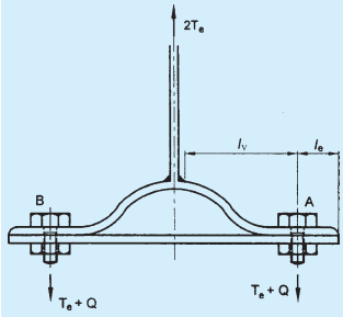
16.4.7 Where prying force, Q as illustrated in Fig. 16 shall be calculated as given below and added to the tension in the bolt:
Q=2lelv[Te−27lelv2βηf
where
lv = distance from the bolt centreline to the toe of the fillet weld or to half the root radius for a rolled section, and
le= distance between prying force and bolt
centreline and is the minimum of either the end distance or the value given by:
le=1.1tfyβfo
where
β = 2, for non pre-tensioned bolt and 1, for pre-tensioned bolt;
η=1.5;
be= effective width of flange per pair of bolts;
f0= proof stress in consistent units; and
t = thickness of the end plate.
FIG. 16 COMBINED PRYING FORCE AND TENSION
60∘−90∘
91∘−100∘
101∘−106∘
107∘−113∘
114∘−120∘
Between Fusion Faces
Constant, K
0.70
0.65
0.60
0.55
0.50
16.5.3.3 The effective throat thickness of a complete penetration butt weld shall be taken as the thickness of the thinner part joined, and that of an incomplete penetration butt weld shall be taken as the minimum thickness of the weld metal common to the parts joined, excluding reinforcements.
fwn
/
γmw
where
fwn=fu/3,
fu = smaller of the ultimate stress of the weld or of the parent metal, and
γmw= partial safety factor (see Table 5).
16.5.7.1.2 Butt welds
Butt welds shall be treated as parent metal with a thickness equal to the throat thickness, and the stresses shall not exceed those permitted in the parent metal.
16.5.7.1.3 Slot or plug welds
The design shear stress on slot or plug welds shall be as per 16.5.7.1.1.
16.5.7.2 Site welds
The design strength in shear and tension for site welds made during erection of structural members shall be calculated according to 16.5.7.1 but using a partial safety factor γmw of 1.5.
16.5.7.3 Long joints
When the length of the welded joint, lj of a splice or end connection in a compression or tension element is greater than 150 tt , the design capacity of weld (see 16.5.7.1.1), fwd shall be reduced by the factor:
βlw=1.2−150tt
where
lj = length of the joint in the direction of the force transfer, and
tt= throat size of the weld.
16.5.8 Fillet Weld Applied to the Edge of a Plate or Section
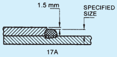
16.5.8.1 Where a fillet weld is applied to the square edge of a part, the specified size of the weld should generally be at least 1.5mm less than the edge thickness
PART 6 STRUCTURAL DESIGN — SECTION 6 STEEL
in order to avoid washing down of the exposed corner (see Fig. 17A).
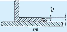
16.5.8.2 Where the fillet weld is applied to the rounded toe of a rolled section, the specified size of the weld should generally not exceed 3/4 of the thickness of the section at the toe (see Fig. 17B).
16.5.8.3 Where the size specified for a fillet weld is such that the parent metal will not project beyond the weld, no melting of the outer cover or covers shall be allowed to occur to such an extent as to reduce the throat thickness (see Fig. 18)
16.5.8.4 When fillet welds are applied to the edges of a plate or section in members subject to dynamic loading, the fillet weld shall be of full size with its leg length equal to the thickness of the plate or section, with the limitations specified in 16.5.8.3.
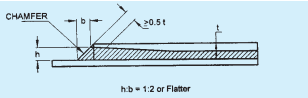
16.5.8.5 End fillet weld, normal to the direction of force shall be of unequal size with a throat thickness not less than 0.5t, where t is the thickness of the part, as shown in Fig. 19. The difference in thickness of the welds shall be negotiated at a uniform slope.
w
P
where
fa = calculated normal stress due to axial force, in N/mm 2 ;
q= shear stress, in N/mm2
P= force transmitted (axial force N or the shear force Q);
tt = effective throat thickness of weld, in mm; and
lw= effective length of weld, in mm.
fa2+3q2≤
3γmwfu
where
fa = normal stresses, compression or tension, due to axial force or bending moment (see 16.5.9), and
q= shear stress due to shear force or tension (see 16.5.9).
16.5.10.1.2 Check for the combination of stresses need not be done for,
a) side fillet welds joining cover plates and flange plates; and
b) fillet welds where sum of normal and shear stresses does not exceed fwd (see 16.5.7.1.1).
16.5.10.2 Butt welds
16.5.10.2.1 Check for the combination of stresses in butt welds need not be carried out provided that,
a) butt welds are axially loaded, and
b) in single and double bevel welds the sum of normal and shear stresses does not exceed the design normal stress, and the shear stress does not exceed 50 percent of the design shear stress.
FIG. 17 FILLET WELDS ON SQUARE EDGE OF PLATE OR ROUND TOE OF ROLLED SECTION
18A Desirable
18B Acceptable because of Full Throat Thickness
18C Not Acceptable because of Reduced Throat Thickness
FIG. 18 FULL SIZE FILLET WELD APPLIED TO THE EDGE OF A PLATE OR SECTION
FIG. 19 END FILLET WELD NORMAL TO DIRECTION OR FORCE
16.5.10.2.2 Combined bearing, bending and shear
Where bearing stress, fbr is combined with bending (tensile or compressive), fb and shear stresses, q under the most unfavorable conditions of loading in butt welds, the equivalent stress, fe as obtained from the following formula, shall not exceed the values allowed for the parent metal:
fe=fb2
where
fe= equivalent stress;
fb= calculated stress due to bending, in N/mm2;
fbr = calculated stress due to bearing, in N/mm 2 ; and
q = shear stress, in N/mm2.
16.5.11 Where a packing is welded between two members and is less than 6 mm thick, or is too thin to allow provision of adequate welds or to prevent buckling, the packing shall be trimmed flush with the edges of the element subject to the design action and the size of the welds along the edges shall be increased over the required size by an amount equal to the thickness of the packing. Otherwise, the packing shall extend beyond the edges and shall be fillet welded to the pieces between which it is fitted.