5.1 Fire Extinguishers/Fixed Firefighting Installations
5.1.1 All buildings depending upon the occupancy use and height shall be protected by fire extinguishers, hose reels, wet riser, down-comer, yard hydrants, automatic sprinkler installation, deluge system, high/medium velocity water spray, foam, water mist systems, gaseous or dry powder system, manual/automatic fire alarm system, etc, in accordance with the provisions of various clauses given below, as applicable:
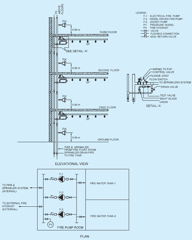
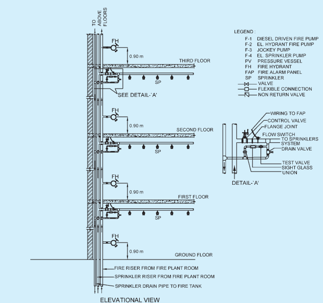
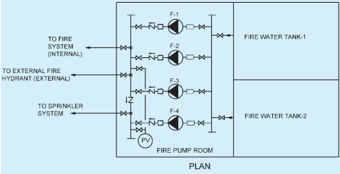
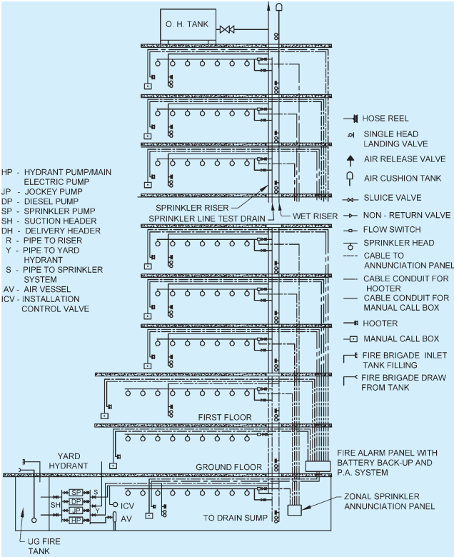
a) These fire extinguishing equipment and their installation shall be in accordance with accepted standards [4(17)]. The extinguishers shall be mounted at a convenient height to enable its quick access and efficient use by all in the event of a fire incidence. The requirements of fire extinguishers/yard hydrant systems/wet riser/down-comer installation and capacity of water storage tanks and fire pumps, etc, shall be as specified in Table 7. The requirements regarding size of mains/risers shall be as given in Table 8. The typical arrangements of down-comer and wet riser installations are shown in Fig. 13. The wet riser shall be designed for zonal distribution ensuring that unduly high pressures are not developed in risers and hose-pipes.
b) First-aid firefighting appliances shall be provided and installed in accordance with good practice [4(18)]. The firefighting equipment and accessories to be installed in buildings for use in firefighting shall also be in accordance with the accepted standard [4(17)] and shall be maintained periodically so as to ensure their perfect serviceability at all times.
c) Valves in fixed firefighting installations shall have supervisory switch with its signalling to fire alarm panel or to have chain(s), pad lock(s), label and tamper-proof security tag(s) with serial number to prevent tampering/unauthorized operation. These valves shall be kept in their intended ‘open’ position.
d) In addition to wet riser or down-comer, first-aid hose reels shall be installed in buildings (where required under Table 7) on all the floors, in accordance with accepted standard [4(19)]. The first-aid hose reel shall be
connected directly to the riser/down-comer main and diameter of the hose reel shall not be less than 19 mm.
e) Wet risers shall be interconnected at terrace level to form a ring and cut-off shall be provided for each connection to enable repair/maintenance without affecting rest of the system.
f) Pressure at the hydraulically remote hydrant and at the highest hydrant shall not be less than 3.5 bar. The pressure at the hydrants shall however not exceed 7.0 bar, considering the safety of operators. It may be planned to provide orifice plates for landing valves to control pressure to desired limit especially at lower levels; this could also be achieved through other suitable means of pressure reducing devices such as pressure controlled hydrant valves.
g) Hydrants for firefighting and hose reels shall be located in the lobby in firefighting shaft. Those hydrants planned to be provided near fire exit staircase on the floor shall be within 5 m from exit door in exit access. Such hydrant cabinet may finish with doors to meet interior finishes with requirement of glass panel to provide visibility to the installations inside and inscribed with the word: 'FIRE HOSE CABINET' of letter size 75 mm in height and 12 mm in width. Such door of the fire hose cabinet need not be fire resistant rated. The location of such cabinets shall be shown on floor plan and duly displayed in the landing of the respective fire exit staircase.
5.1.2 Static Water Storage Tanks and Pump House
5.1.2.1 Static water storage tanks
A satisfactory supply of water for the purpose of firefighting shall always be available in the form of underground/terrace level static storage tank with capacity specified for each building with arrangements or replenishment.
Water for the hydrant services shall be stored in an easily accessible surface/underground lined reservoir or above ground tanks of steel, concrete or masonry. The effective capacity of the reservoir above the top of the pump casing (flooded suction) for various types of occupancies shall be as indicated in Table 7.
Water for firefighting shall be stored in two or more interconnected compartments of equal size to facilitate cleaning and maintenance of the tanks without interrupting the water availability for firefighting.
To prevent stagnation of water in the static water storage tank, the suction tank of the domestic water supply shall
be fed only through an overflow arrangement from the fire water storage tanks to maintain the level therein at the minimum specified capacity.
Alternatively, domestic and fire water can be stored in two interconnected compartments as mentioned above. The suction inlet(s) for the domestic water pumps shall be so located at an elevation that minimum water requirements for firefighting as stated in Table 7 will be always available for fire pumps.
The static storage water supply required for the above mentioned purpose shall entirely be accessible to the fire engines of the local fire service. Suitable number of manholes shall be provided for inspection, repairs, insertion of suction hose, etc. As an alternative to the arrangement of manholes to allow access from the top, suitable arrangement to enable efficient access to the tank by the firemen from the adjoining fire pump room having direct access from the ground level, shall be made. The underground fire water storage tank(s) shall not be more than 7 m in depth from the level having fire brigade draw-out connection, while the draw-out connection shall not be more than 5 m away from the tank wall.
The covering slab shall be able to withstand a total vehicular load of 45 t (or as applicable) equally divided as a four-point load when the slab forms a part of pathway/driveway.
The static water storage tank shall be provided with a fire brigade collecting head with 4 number 63 mm diameter (2 number 63 mm diameter for pump with capacity 1 400 litre/min) instantaneous male inlets arranged in a valve box at a suitable point at street level. The same shall be connected to the static tank by a suitable fixed galvanized iron pipe not less than 150 mm in diameter to discharge water into the tank when required at the rate of 2 250 litre/min, if tank is in the basement or not approachable for the fire engines.
Each of the static water storage tanks shall also be provided with a fire brigade draw out collecting head with 63 mm diameter instantaneous male draw out arranged in a valve box at a suitable point at street level. This draw out shall be connected to galvanized iron pipe of 100 mm diameter with foot valve arrangement in the tank.
5.1.3 Automatic Sprinkler Installation
The requirements shall be as given below:
a) Automatic sprinklers shall be installed wherever required in terms of Table 7 throughout the building in accordance with good practice [4(20)].
b) If selective sprinklering is adopted, there is a real danger of a fire starting in one of the unsprinklered area gathering momentum spreading to other areas and reaching the sprinklered areas as a fully developed fire. In such an event, the sprinklers can be rendered useless or ineffective.
c) Automatic sprinklers shall be installed in false ceiling voids exceeding 800 mm in height.
d) Installation of sprinklers may be excluded in any area to be used for substation and DG set.
e) In areas having height or above such as in atria, sprinkler installations may be rendered ineffective and hence may be avoided.
f) Pressure in sprinkler system shall not exceed 12 bar or else high pressure sprinkler to be installed for above 12 bar operations.
g) The maximum floor area on any one floor to be protected by sprinklers supplied by any one sprinkler system riser from an installation control valve shall be based on system protection area limitations considering maximum floor area on any one floor to be 4 500 m² for all occupancies except industrial and hazardous occupancies, where Authorities
PART 4 FIRE AND LIFE SAFETY
shall be consulted for advice based on type and nature of risk.
h) Sprinkler installation control valves, shall be installed inside the fire pump room.
j) For industrial buildings, such installation control valves may be installed outside the building and Authorities shall be consulted in situations where it is not possible to locate them inside the buildings. It is advisable to provide electrically operated siren for each valve outside the buildings in addition to water gongs in such case.
k) The sprinkler flow switches provided shall be monitored by fire alarm panel.
m) It is essential to make provisions for avoiding water from sprinkler/hydrant operation entering lifts and electrical rooms.
n) Ramps at all levels shall be protected with sprinklers.
5.1.4 Automatic High Velocity and Medium Velocity Water Spray Systems
Automatic high velocity water spray or emulsifying system shall be provided for protection of outdoor and/or indoor oil-cooled transformers as applicable in accordance with good practice [4(21)] where applicable (see Annex E). Also, medium velocity water spray system shall be provided for tankage (where applicable), conveyors, cable galleries and other occupancies listed in good practice [4(21)].
5.1.5 Fixed Foam Installation
Fixed foam generating system shall be provided for protection of oil storage area for boilers with its ancillary storage of furnace oils in basement. Fixed foam installations can be low, medium or high expansion types, which can be provided based on the type of fire hazards identified in the facility. High expansion foams are used for cable tunnels and other confined areas. Design and installation of foam systems shall be governed by good practice [4(22)].
5.1.6 Gas Based Suppression System
Gas based fire extinguishing installation shall be provided in accordance with good practice on premises where water or foam cannot be used for fire extinguishing because of the special nature of the contents of the buildings/areas to be protected where either the building(s) have very limited manpower or unmanned. The protection design for fixed carbon dioxide fire extinguishing system shall conform to good practice in all respects. For some special fire risk/essential applications, carbon dioxide may not be suitable and alternate provisions shall be made as per relevant standards (see 5.1.9).
5.1.7 Firefighting equipment shall be suitably located and clearly marked by luminous signs.
5.1.8 Automatic Water Mist Systems
These systems involve the use of fine water sprays for the efficient extinguishment of fires. These systems may be provided to protect areas in buildings for the uses as specified in good practice [4(24)].
5.1.9 Extinguishing Systems with Clean Agents
Alternative systems for halon gas protection systems shall be provided where necessary as prescribed in this Part. These shall be in accordance with the accepted standards [4(25)].
5.2 Fire Detection and Alarm System
See 4.9.
5.3 The fixed firefighting installations and systems shall be maintained in accordance with good practice [4(26)] and the Part 12 ‘Asset and Facility Management’ of the Code.