Calculation of Crack Width
Provided that the strain in the tension reinforcement is limited to , the design surface crack width, which should not exceed the appropriate value given in 34.3.2 may be calculated from the following equation:
Design surface crack width:
where
distance from the point considered to the surface of the nearest longitudinal bar.
minimum cover to the longitudinal bar,
average steel strain at the level considered,
overall depth of the member, and
depth of the neutral axis.
The average steel strain may be calculated on the basis of the following assumption:
The concrete and the steel are both considered to be fully elastic in tension and in compression. The elastic modulus of the steel may be taken as and the elastic modulus of the concrete is as derived from the equation given in 5.2.3.1 both in compression and in tension.
Alternatively, as an approximation, it will normally be satisfactory to calculate the steel stress on the basis of a cracked section and then reduce this by an amount equal to the tensile force generated by the triangular distributions, having a value of zero at the neutral axis and a value at the centroid of the tension steel of instantaneously, reducing to in the long-term, acting over the tension zone divided by the steel area.
These assumptions are illustrated in Fig. 50,
For a rectangular tension zone, this gives:
where
= area of tension reinforcement,
b = width of the section at the centroid of the tension steel,
= strain at the level considered, calculated ignoring the stiffening of the concrete in the tension zone,
a = distance from the compression face to the point at which the crack width is being calculated, and
effective depth.
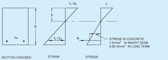
overall depth of the section,
depth from the compression face to the neutral axis,
= maximum compressive stress in the concrete,
NATIONAL BUILDING CODE OF INDIA 2016
tensile stress in the reinforcement, and
modulus of elasticity of the reinforcement.
FIG. 50