23.1 General
The provisions of 22.2 for beams apply to slabs also.
1 For slabs spanning in two directions, the shorter of the two spans should be used for calculating the span to effective depth ratios.
2 For two-way slabs of shorter spans (up to 3.5 m) with mild steel reinforcement, the span to overall depth ratios given below may generally be assumed to satisfy vertical deflection limits for loading class up to 3 kN/m .
a) Simply supported slabs : 35
b) Continuous slabs : 40
For high strength deformed bars of Grade Fe 415, the values given above should be multiplied by 0.8.
23.2 Slabs Continuous Over Supports
Slabs spanning in one direction and continuous over supports shall be designed according to the provisions applicable to continuous beams.
23.3 Slabs Monolithic with Supports
Bending moments in slabs (except flat slabs) constructed monolithically with the supports shall be calculated by taking such slabs either as continuous over supports and capable of free rotation, or as members of a continuous framework with the supports, taking into account the stiffness of such supports. If such supports are formed due to beams which justify fixity at the support of slabs, then the effects on the supporting beam, such as, the bending of the web in the transverse direction of the beam and the torsion in the longitudinal direction of the beam, wherever applicable, shall also be considered in the design of the beam.
23.3.1 For the purpose of calculation of moments in slabs in a monolithic structure, it will generally be sufficiently accurate to assume that members connected to the ends of such slabs are fixed in position and direction at the ends remote from their connections with the slabs.
23.3.2 Slabs Carrying Concentrated Load
23.3.2.1 If a solid slab supported on two opposite edges, carries concentrated loads the maximum bending moment caused by the concentrated loads shall be assumed to be resisted by an effective width of slab (measured parallel to the supporting edges) as follows:
a) For a single concentrated load, the effective width shall be calculated in accordance with the following equation provided that it shall not exceed the actual width of the slab:
where
effective width of slab,
k = constant having the values given in Table 14 depending upon the ratio of the width of the slab (l') to the effective span l_{ef},
distance of the centroid of the concentrated load from nearer support,
effective span, and
a = width of the contact area of the concentrated load from nearer support measured parallel to the supported edge.
And provided further that in case of a load near the unsupported edge of a slab, the effective width shall not exceed the above value nor half the above value plus the distance of the load from the unsupported edge.
| Sl No. | k for Simply Supported Slabs | k for Continuous Slabs | |
|---|---|---|---|
| (1) | (2) | (3) | (4) |
| i) | 0.1 | 0.4 | 0.4 |
| ii) | 0.2 | 0.8 | 0.8 |
| iii) | 0.3 | 1.16 | 1.16 |
| iv) | 0.4 | 1.48 | 1.44 |
| v) | 0.5 | 1.72 | 1.68 |
| vi) | 0.6 | 1.96 | 1.84 |
| vii) | 0.7 | 2.12 | 1.96 |
| viii) | 0.8 | 2.24 | 2.08 |
| ix) | 0.9 | 2.36 | 2.16 |
| x) | 1.0 and above | 2.48 | 2.24 |
b) For two or more concentrated loads placed in a line in the direction of the span, the bending moment per metre width of slab shall be calculated separately for each load according to its appropriate effective width of slab calculated as in (a) and added together for design calculations.
c) For two or more loads not in a line in the direction of the span, if the effective width of slab for one load does not overlap the effective width of slab for another load, both calculated as in (a) above, then the slab for each load can be designed separately. If the effective width of slab for one load overlaps the effective width of slab for an adjacent load, the overlapping portion of the slab shall be designed for the combined effect of the two loads.
d) For cantilever solid slabs, the effective width shall be calculated in accordance with the
PART 6 STRUCTURAL DESIGN — SECTION 5 CONCRETE: 5A PLAIN AND REINFORCED CONCRETE
following equation :
where
distance of the concentrated load from the face of the cantilever support, and
a = width of contact area of the concentrated load measured parallel to the supporting edge.
Provided that the effective width of the cantilever slab shall not exceed one-third the length of the cantilever slab measured parallel to the fixed edge.
And provided further that when the concentrated load is placed near the extreme ends of the length of cantilever slab in the direction parallel to the fixed edge, the effective width shall not exceed the above value, nor shall it exceed half the above value plus the distance of the concentrated load from the extreme end measured in the direction parallel to the fixed edge.
23.3.2.2 For slabs other than solid slabs, the effective width shall depend on the ratio of the transverse and longitudinal flexural rigidities of the slab. Where this ratio is one, that is, where the transverse and longitudinal flexural rigidities are approximately equal, the value of effective width as found for solid slabs may be used. But as the ratio decreases, proportionately smaller value shall be taken.
23.3.2.3 Any other recognized method of analysis for cases of slabs covered by 23.3.2.1 and 23.3.2.2 and for all other cases of slabs may be used with the approval of the Engineer-in-Charge.
23.3.2.4 The critical section for checking shear shall be as given in 33.2.4.1.
23.4 Slabs Spanning in Two Directions at Right Angles
The slabs spanning in two directions at right angles and carrying uniformly distributed load may be designed by any acceptable theory or by using coefficients given in Annex D. For determining bending moments in slabs spanning in two directions at right angles and carrying concentrated load, any accepted method approved by the Engineer-in-Charge may be adopted.
NOTE — The most commonly used elastic methods are based on Pigeaud's or Wester-guard's theory and the most commonly used limit state of collapse method is based on Johansen's yield-line theory.
23.4.1 Restrained Slab with Unequal Conditions at Adjacent Panels
In some cases the support moments calculated from Table 30 for adjacent panels may differ significantly. The following procedure may be adopted to adjust them:
a) Calculate the sum of the midspan moment and the average of the support moments (neglecting signs) for each panel.
b) Treat the values from Table 30 as fixed end moments.
c) According to the relative stiffness of adjacent spans, distribute the fixed end moments across the supports, giving new support moments.
d) Adjust midspan moment such that, when added to the support moments from (c) (neglecting signs), the total should be equal to that from (a).
If the resulting support moments are significantly greater than the value from Table 30, the tension steel over the supports will need to be extended further. The procedure should be as follows:
-
Take the span moment as parabolic between supports: its maximum value is as found from (d).
-
Determine the points of contraflexure of the new support moments [from (c)] with the span moment [from (1)].
-
Extend half the support tension steel at each end to at least an effective depth or 12 bar diameters beyond the nearest point of contraflexure.
-
Extend the full area of the support tension steel at each end to half the distance from (3).
23.5 Loads on Supporting Beams
The loads on beams supporting solid slabs spanning in two directions at right angles and supporting uniformly
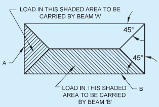
FIG. 7 LOAD CARRIED BY SUPPORTED BEAMS
distributed loads, may be assumed to be in accordance with Fig. 7.