Glass railings are generally sought in commercial applications (such as in malls) and in certain domestic villas, etc. Glass of appropriate thickness when used as a railing can provide transparency and when engineered properly can provide structural performance too.
The basic requirement of a parapet which a glass railing (if so used) intends to substitute shall be met with. This
includes protecting people from falling and in some cases to control movement. Careful consideration including in design shall be made where glass railings are used.
NOTE — Notwithstanding the above, the potential benefits including safety (through psychological aspects) of regular railings shall be borne in mind.
H-2 Preliminary Considerations
In the assessment of the need for a railing and the type
PART 6 STRUCTURAL DESIGN — SECTION 8 GLASS AND GLAZING
of railing to be provided, the designer should give consideration to the likely hazards, the building use and the risks to building users. Where, in a building, more than one use of the building is anticipated, either the railing design should be chosen to suit the worst case, or more than one type of railing should be provided, as appropriate, to the location. Generally when there is a change in adjacent levels (600 mm in dwellings, 380 mm in other buildings) a railing is needed to restrict movement of people.
The railing adopted should be designed so as to minimise the risk of persons falling, rolling, sliding or slipping through gaps in the railing. In dwellings and other buildings which can be accessed by children, gaps in railing or infill should not be large enough to permit a sphere of 100 mm diameter to pass through, making due allowance for deflection under load.
The designer should ensure all the elements of the railing system satisfy the criteria given in available relevant standards.
For general safety, the finished barrier should have no sharp edges or projections that could cause injury to persons or clothing. Infill panels and balusters are intended to provide support and protection to users, and should be designed to restrain people without causing additional injury from sharp edges, thin sections, open-ended tubes, projecting details, etc.
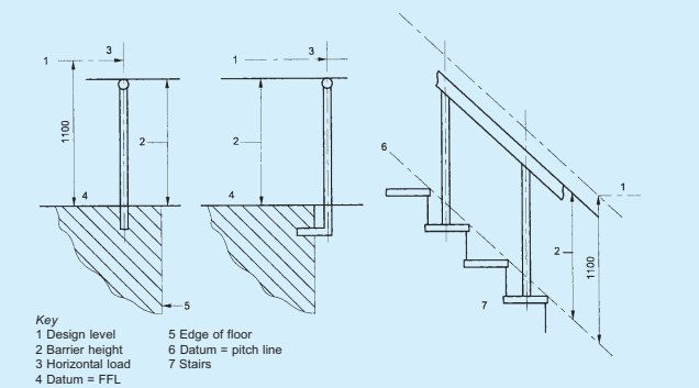
The design shall be based on the horizontal UDL (uniformly distributed load) should be applied at a notional height of 1.1 m above finished floor level, even though the minimum permissible height of the railing may be less (The notional design height of 1.1 m is chosen as being representative of the height of the centre of gravity of a human being above the datum level).
H-3 Glass Railing Types
There are four common types of railing that used to fix glass.
a) Full height railing — Where glass forms part or whole of a wall element, the railing should be carefully designed as per the relevant existing standards and as per this Section, if any part of the glass comes below the minimum railing height (see Table 35).
b) Railings with a glass infill panel — In this type of railing, the main frame of the railing (that is, top rail and baluster) should be designed to withstand the loads applied to the top rail and the glass should be used to form infill panels. It should be noted that the glass provides no support to the main frame. This can be further sub-categorized into 4 types:
Glass supported on vertical edges only—This may involve the vertical edges of the glass being supported in a rebate into the side of each vertical post. The top and bottom edges of the glass are exposed. The glass may also be supported by patch fittings fixed to the posts. In all cases a handrail is required.
Glass supported on horizontal edges only — This may involve a handrail at the top, and a channel or a rail at the base of the glass. In this case the handrail should be designed to carry the railing load with the glass designed to carry the infill load. Glass supported on all four edges.
Glass fixed by patch/bolted fittings — This system requires the use of two rows of bolts (commonly) to provide a stiff fixing which minimises panel deflection. There are a variety of bolt fixing types available in the market so design and performance information should be sought for each type. The purpose of these fixings is to transfer the force applied to the railing into the support structure. These fixings occupy a small surface area on the glass which can produce high stresses in the glass, so careful analysis is required to determine suitable glass thickness, fixing spacing and size.
c) Free standing glass protective railing — In this type of railing, the glass should be designed to withstand the design loads. Each glass plate should be rigidly clamped to the structure along its bottom edge, the handrail attached to the top edge of the glass and there should be no balusters. In the event that a free standing railing is supplied without a handrail, each panel should be able to withstand the entire appropriate design load. This applies to vertical glazing and glass within 15° of vertical. Adequate provision for drainage of water should be made in the base structure to avoid any water ponding which may cause delamination issue
d) Bracket systems — These systems are an extension of the bolt fixed system where the bolts are part of a bracket and the bracket is fixed to the floor or the face of a concrete slab, steel or timber structure. The use of these systems shall be investigated carefully as they can develop very high stresses in the glass where the brackets are located. The design shall balance glass thickness and bracket location to produce an adequate system. Some systems may be designed to produce test data,
to justify their use. This data shall be studied carefully as there have been some cases where such data has been shown to be inadequate. Proper interpretation of these test data shall also become necessary.
Table 35Minimum Barrier Heights [Clause H-3 (a)]
Sl No.(1)
Use(2)
Position(3)
Heights mm(4)
i)
Single family dwelling
a) Barriers in front of a window up to 10 floors
800
b) Barriers in front of a window from 11th floor to 20th floor
1 100
c) Barriers in front of a window above 21st floor
1 200
d) Stairs, landings, ramps, edges of internal floors
900
e) External balconies including balconet, edges of roofs:
1) up to 20th floor
1 100
2) 21st floor and above
1 200
ii)
All other uses
a) Barrier in front of a window
800
b) Stairs
900
c) Balconies and stands, etc, having fixed seating within 530 mm of the barrier
800
d) Balconies and stands, etc, having fixed seating within 530 mm of the barrier, provided the sum of the barrier width and the barrier height is greater than 975 mm
750
e) Other positions including balconets
1 100
H-4 Design Considerations
The designer shall first determine the purpose of the railing. Once this is done, the appropriate load requirement can be derived. Typical values (minimum requirements) of railing loads to be chosen are given in Table 36. (If so desired by the designer, higher values than that in the Table 36 may also be chosen.)
H-4.1 General
Railings should be designed to resist the most unfavourable likely imposed loads and wind loads separately without unacceptable deflections or distortions. Heights of railings shall be same as that for parapet walls as per other Parts of the Code. The railing height above datum is defined in Fig. 22. The minimum heights for each railing location shall be as given in Table 35.
The height of glass railings installed on top of low parapet walls should be measured from the top of the parapet and not at walk level.
For railings, either permissible stress or limit state design procedure should be used, according to the recommended procedures. When using limit state design, the partial safety factors for loads and materials should be those recommended by the appropriate standard for relevant materials. The deflection of the railing shall be determined as per serviceability limit state.
H-4.2 Loadings
Minimum horizontal imposed loads appropriate to the design of parapets, railings, balustrades and other
NOTE — In design, the horizontal uniformly distributed line load acts at a height of 1.1m above datum level, irrespective of the actual height of the element.
FIG. 22 DATUM, BARRIER HEIGHT AND DESIGN HEIGHT
PART 6 STRUCTURAL DESIGN — SECTION 8 GLASS AND GLAZING
NOTE — H is the height at which the applied load (horizontal design load) is located and it need not be the height of the barrier itself.
elements of structure intended to retain, stop or guide people, should be determined in accordance with Table 36, which recommends a uniformly distributed line load for the railing and a uniformly distributed and point load applied to the infill.
NOTE — These are not additive and should be considered as three separate load cases, all loads being determined according to the type of occupancy which reflects the possible in-service conditions.
Horizontal uniformly distributed line load should be applied at design height as presented in Table 36 or at
design level (1 100 mm) for railings higher than the design height.
Uniformly distributed load should be applied to the area below the design height.
Point load should be applied at the most onerous point anywhere on the railing structure.
NOTE — For clarity, the design level (the level at which the horizontal uniformly distributed line load ought to be considered to act) is shown in Fig. 23.
In general, the load combinations as described in H-4.2.1 to H-4.2.3 should be applied.
Building
Element
Strength
Height (H)
Single family dwelling
Stairs landings, ramps edges of internal floors
0.36 kN/m
900 mm for all elements
External balconies and edges of roofs
0.74 kN/m
1 100 mm
Factories and warehouses (light traffic)
Stairs, ramps
0.36 kN/m
900 mm
Landing and edges of floor
0.36 kN/m
1 100 mm
Residential institutional, educational, office and public building
All location
0.74 kN/m
900 mm for flights otherwise 1 100 mm
Assembly
Within 530 mm in front of fixed seating
1.5 kN/m
800 mm (H1)
All other locations
3.0 kN/m
900 mm for flights elsewhere 1 100 mm (H2)
Retail
All locations
1.5 kN/m
900 mm for flights otherwise 1 100 mm
All buildings
At opening windows
800 mm
At glazing to changes of level
To provide containment
Below 800 mm
FIG. 23 HEIGHT LIMIT FOR THE UNIFORM LOADING FOR VARIOUS CATEGORY OF BUILDINGS
Table 36Minimum Horizontal Imposed Loads for Parapets, Barriers and Balustrades (Clauses H-4.2 and H-4.4)
Sl No.
Type of Occupancy for Part of the Building or Structure
Examples of Specific Use
Horizontal Uniformly Distributed Line Load
Uniformly Distributed Load Applied to the Infill
A Point Load Applied to Part of the Infill
kN/m
kN/m2
kN
(1)
(2)
(3)
(4)
(5)
(6)
i)
Domestic and residential activities
a) All areas within or serving exclusively one single family dwelling including stairs, landings, etc, but excluding external balconies and edges of roofs
0.36
0.5
0.25
b) Other residential, that is, houses of multiple occupancy and balconies, including Juliette balconies and edges of roofs in single family dwellings
0.74
1.0
0.5
ii)
Offices and work areas not included elsewhere, including storage areas
a) Light access stairs and gangways not more than 600 mm wide
0.22
—
—
b) Light pedestrian traffic routes in industrial and storage buildings except designated escape routes
0.36
0.5
0.25
c) Area not susceptible to overcrowding in office and institutional buildings, also industrial and storage buildings except as given above
0.74
1.0
0.5
iii)
Areas where people might congregate
Areas having fixed seating within 530 mm of the barrier, balustrade or parapet
1.5
1.5
1.5
iv)
Area with tables or fixed seatings
Restaurants and bars
1.5
1.5
1.5
v)
Areas without obstacles for moving people and not susceptible to overcrowding
a) Stairs, landings, corridors, ramps
0.74
1.0
0.5
b) External balconies including balconets and edges of roofs. Footways and pavements within building curtilage adjacent to basement/sunken areas
0.74
1.0
0.5
vi)
Areas susceptible to overcrowding
a) Footways or pavements less than 3 m wide adjacent to sunken areas
1.5
1.5
1.5
b) Theatres, cinemas, discotheques, bars, auditoria, shopping malls, assembly areas, studio. Footways or pavements greater than 3 m wide adjacent to sunken areas.
3.0
1.5
1.5
vii)
Retail areas
All retail areas including public areas of banks/building societies or betting shops
1.5
1.5
1.5
viii)
Vehicular
Pedestrian areas in car parks, including stairs, landings, ramps, edges or internal floors, footways, edges of roofs
1.5
1.5
1.5
H-4.2.1 Free Standing Glass Protective Railing (Without any Balusters)
It requires five design loadings to be taken into account:
a) Line load (Horizontal UDL), in kN/m
b) UDL (Infill UDL), in kN/m2.
c) Concentrated load, in kN.
d) Impact force.
e) Shot bag test load (see Annex E).
H-4.2.2 Railing with Glass Infill Panel
It requires three design loadings to be taken into account:
a) UDL (Infill UDL), in kN/m².
b) Concentrated load, in kN.
c) Impact force, in kN.
H-4.2.3 Full Height Railing
It requires three design loadings to be taken into account:
a) Line load (Horizontal UDL), in kN/m.
b) UDL (Infill UDL), in kN/m².
c) Concentrated load, in kN.
H-4.3 Wind Loads
External railings should be designed to resist the wind loads given in good practice [8-5(7)].
PART 6 STRUCTURAL DESIGN — SECTION 8 GLASS AND GLAZING
H-4.4 Deflection
Railings for the protection of people should be of adequate strength and stiffness to sustain the applied loads given in Table 36. In addition, a railing that is structurally safe should not possess flexibility to such an extent so as to create a false alarm to building users when subject to normal service conditions. Therefore, for serviceability considerations, the limiting condition for deflection appropriate for a railing for the protection of people is that the total horizontal displacement of the railing at any point from its original unloaded position and should not exceed the deflection limits determined from the relevant structural design code (where applicable) for the material used, or 25 mm, whichever is the smaller. Where the infill of a railing is subjected to the imposed loads given in Table 36, or if appropriate, other calculated design loads, the displacement of any point of the railing should not exceed H/65 or 25 mm, whichever is lower.