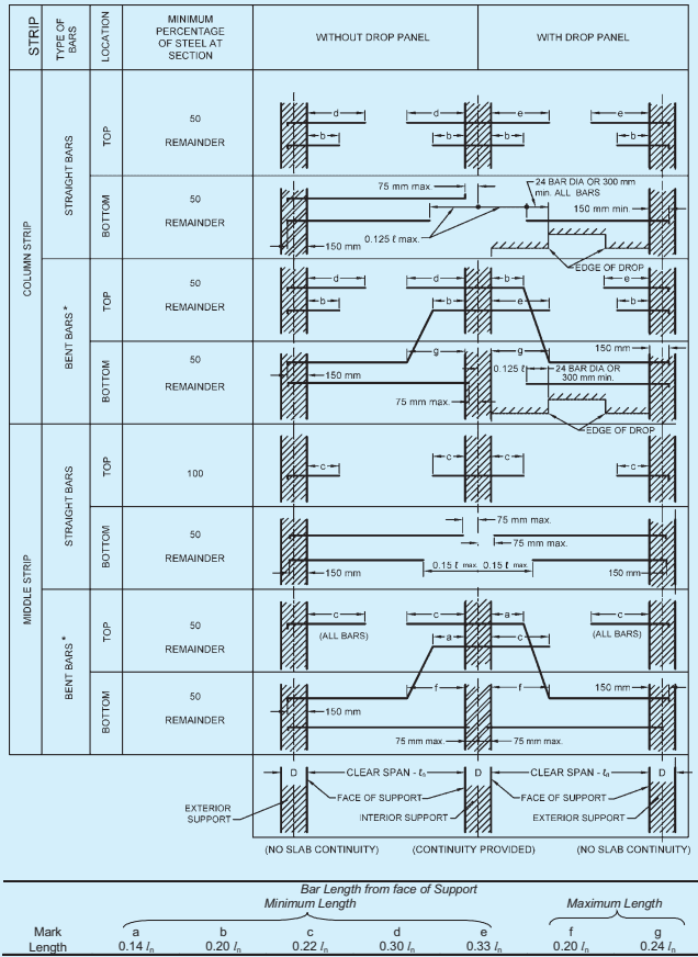
30.5.1 Assumptions
The bending moments and shear forces may be determined by an analysis of the structure as a continuous frame and the following assumptions may be made:
a) The structure shall be considered to be made up of equivalent frames on column lines taken longitudinally and transversely through the building. Each frame consists of a row of equivalent columns or supports, bounded laterally by the centre-line of the panel on each side of the centre-line of the columns or supports. Frames adjacent and parallel to an edge shall be bounded by the edge and the centre-line of the adjacent panel.
b)
Each such frame may be analysed in its entirety, or, for vertical loading, each floor thereof and the roof may be analysed separately with its columns being assumed fixed at their remote ends. Where slabs are thus analysed separately, it may be assumed in determining the bending moment at a given support that the slab is fixed at any support two panels distant therefrom provided the slab continuous beyond the point.
c) For the purpose of determining relative stiffness of members, the moment of inertia of any slab or column may be assumed to be that of the gross cross-section of the concrete alone.
d) Variations of moment of inertia along the axis of the slab on account of provision of drops shall be taken into account. In the case of recessed or coffered slab which is made solid in the region of the columns, the stiffening effect may be ignored provided the solid part of the slab does not extend more than 0.15lef , into the span measured from the centre-line of the columns. The stiffening effect of flared column heads may be ignored.
30.5.2 Loading Pattern
30.5.2.1 When the loading pattern is known, the structure shall be analysed for the load concerned.
30.5.2.2 When the live load is variable but does not exceed three-quarters of the dead load, or the nature of the live load is such that all panels will be loaded simultaneously, the maximum moments may be assumed to occur at all sections when full design live load is on the entire slab system.
30.5.2.3 For other conditions of live load/dead load ratio and when all panels are not loaded simultaneously,
a) maximum positive moment near midspan of a panel may be assumed to occur when three-quarters of the full design live load is on the panel and on alternate panels; and
b) maximum negative moment in the slab at a support may be assumed to occur when three-quarters of the full design live load is on the adjacent panels only.
PART 6 STRUCTURAL DESIGN — SECTION 5 CONCRETE: 5A PLAIN AND REINFORCED CONCRETE
30.5.2.4 In no case shall design moments be taken to be less than those occurring with full design live load on all panels.
30.5.3 Negative Design Moment
30.5.3.1 At interior supports, the critical section for negative moment, in both the column strip and middle strip, shall be taken at the face of rectilinear supports, but in no case at a distance greater than 0.175l1 from the centre of the column where l1 is the length of the span in the direction moments are being determined, measured centre-to-centre of supports.
30.5.3.2 At exterior supports provided with brackets or capitals, the critical section for negative moment in the direction perpendicular to the edge shall be taken at a distance from the face of the supporting element not greater than one-half the projection of the bracket or capital beyond the face of the supporting element.
30.5.3.3 Circular or regular polygon shaped supports shall be treated as square supports having the same area.
30.5.4 Modification of Maximum Moment
Moments determined by means of the equivalent frame method, for slabs which fulfil the limitations of 30.4 may be reduced in such proportion that the numerical sum of the positive and average negative moments is not less than the value of total design moment Mo specified in 30.4.2.2.
30.5.5 Distribution of Bending Moment Across the Panel Width
30.5.5.1 Column strip : Negative moment at an interior support
At an interior support, the column strip shall be designed to resist 75 percent of the total negative moment in the panel at that support.
30.5.5.2 Column strip : Negative moment at a exterior support
a) At an exterior support, the column strip shall be designed to resist the total negative moment in the panel at that support.
b) Where the exterior support consists of a column or a wall extending for a distance equal to or greater than three-quarters of the value of l2 the length of span transverse to the direction moments are being determined, the exterior negative moment shall be considered to be uniformly distributed across the length