Testing of Systems with Mechanical Anchorages
B-1 Static Load Test with Tendon-anchorage Assembly
The aim of the test is to assess the performance of the tendon-anchorage assembly and to determine any decrease of the breaking load of the prestressing steel due to the influence of the anchorage. The test is also relevant for couplings.
B-1.1 Test Specimen
The tendon and anchorage to be tested should be assembled according to the envisaged application, using all the components necessary for anchoring the tendon. The geometrical configuration of the individual wires, strands or bars in the specimen should be identical to that of the actual tendon-anchorage assembly and so the following properties should be established:
a) Main geometrical and mechanical properties of the prestressing steel used in the test;
b) Actual mean breaking load;
c) Mean total elongation at maximum load;
d) Mean cross-section;
e) Surface characteristics, etc; and
f) Minimum of 3 single unit tensile tests.
Relevant geometrical and mechanical properties of anchorage components should also be determined. The free length of the individual wires, strands or bars in the specimen to be tested should be not less than 3.0 m.
If one grade of prestressing steel of the same type is to be used with the same type of anchorage, the tests
should be performed using the grade with the highest characteristic tensile strength.
B-1.2 Test Procedure
The tendon specimen is mounted in a calibrated test rig or testing machine and should be stressed in increments of force corresponding to 20 percent, 40 percent, 60 percent and 80 percent of the characteristic tensile strength of the prestressing steel, . In each increment the force is increased at a constant force rate corresponding to about per min. At the 80 percent level, the force is held constant for . Subsequently, the force is increased gradually to total failure.
The described test procedure is normally applicable to systems where the prestressing steel is connected to the anchorage before applying the stressing force. In systems where the prestressing level is locked in the anchorage after the stressing force has been applied, the above test procedure should be adapted as follows:
a) The tendon should be mounted in the test rig or testing machine, using an identical geometrical configuration of the individual wires, strands or bars in the specimen to that in the actual tendon-anchorage assembly.
b) The tendon should be stressed at one end with the equipment used on the construction site in steps as described to 80 percent of the characteristic tensile strength of prestressing steel, .
PART 6 STRUCTURAL DESIGN — SECTION 5 CONCRETE: 5B PRESTRESSED CONCRETE
c) After the tendon has been locked at this force, the further testing procedure should be as previously described.
The test can be carried out in the manner described in the first instance if it can be proved that locking the prestressing steel in anchorage after the stressing force has been applied has no significant influence on the behaviour of the tendon-anchorage assembly.
B-1.3 Measurements and Observations
The following measurements and observations should be made and recorded:
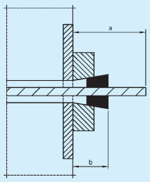
a) Relative force and time dependent displacement of the prestressing steel with respect to the anchorage (see Fig. 17),
b) Relative force and time dependent displacement between the individual components of the anchorage (see Fig. 17),
c) Deformation of the anchorage components,
d) Elongation of the tendon on free length up to failure,
e) Measured ultimate force , and
f) Location and mode of failure.
B-1.4 Test Requirements
The test result should meet the following requirements:
a) Residual deformations of anchorage components after the test should confirm the reliability of the anchorage.
b) The increase in the displacements between the anchorage components as well as between the prestressing steel and anchorage components
17A BEFORE LOCKING
should not be disproportionate to the increase in tendon force.
c) The above relative displacements during the load stage should stabilize within the first of the load duration of .
d) The mode of failure of tendon should be by the fracture of the prestressing steel. Failure of the tendon should not be induced by the failure of anchorage components.
e) The measured anchorage efficiency is:
where
The total elongation in free length of the tendon under the load should be not less than 2 percent.
B-2 Dynamic Load Test with Tendon-anchorage Assembly
The aim of the test is to determine the capacity of the tendon-anchorage assembly under load fluctuations as an indication of the reliability and durability of the assembly.
B-2.1 Test Specimen
The type of specimen should correspond to the requirements of section B-1.1. If one grade of prestressing steel of the same type is to be used with the same type of anchorage, the tests should be performed with prestressing steel using the grade with the highest characteristic tensile strength.
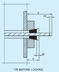
FIG. 17 DISPLACEMENTS DURING TESTING
Where the capacity of the testing machine to be used could be exceeded, the number of wires, strands or bars in the tendon-anchorage assembly to be tested may be reduced, provided that the prestressing steel units with the most severe angular deviation of tendon axis from the prescribed are included and that the test results are representative for the complete tendon.
B-2.2 Test Procedure
The test should be performed in a tensile testing machine with a pulsator at a constant force frequency of not more than 500 load cycles per min, and with a constant upper force of 65 percent of the characteristic strength of the prestressing steel. The range of forces, should be maintained at a constant level throughout testing.
The specimen should be tested in such a way that secondary oscillations are precluded. When assembling the specimen and fitting it in the testing machine, special care should be taken to ensure that the force is evenly distributed to all the tensile elements of the tendon. In the case of grouted tendons special devices may be used to avoid premature fretting failure of the prestressing steel remote from the anchorage.
B-2.3 Measurements and Observations
The following measurements and observations should be made and recorded:
a) Relative displacement between prestressing steel and individual anchorage components as well as between the anchorage components themselves, depending on load and on number of load cycles (see Fig. 17).
b) Examination of anchorage components and prestressing steel after test with respect to fatigue damage and deformation.
B-2.4 Steel Requirements
Each test result should meet the following requirements:
a) Fatigue failure of anchorage components should not occur.
b) The minimum fatigue strength of a post-tensioning system should be .
The fatigue strength is defined as the stress range which is endured for 2 million cycles without failure of 5 percent of the initial cross-section of the tested tendon at beginning of the test.
B-3 Load Transfer Test
With the load transfer test, the transfer of the prestressing force from the mechanical anchorage and its components to the concrete should be verified.
B-3.1 Test Specimen
The test specimen is schematically depicted in Fig. 18. The specimen should contain those anchorage components which will also be embedded in the structural concrete. Their arrangement should comply with the practical application and with the prestressing contractor's specification.
The test specimen should be a concrete prism tested in axial compression.
The part of the specimen containing the anchorage should be provided with bursting reinforcement of the same size and configuration as specified for the particular system and tendon, respectively. Reinforcement may be used for the assembly of the bursting reinforcement. It should not be considered part of the technical approval, if the following conditions are not complied with:
a) Longitudinal bars have a total cross-section more than 200 mm².
b) Stirrups, that is, the secondary reinforcement, uniformly distributed along the height of specimen, should constitute more than 0.05 t steel per cubic metre of concrete.
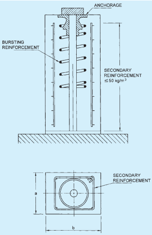
FIG. 18 TEST SPECIMEN FOR LOAD TRANSFER TEST
PART 6 STRUCTURAL DESIGN — SECTION 5 CONCRETE: 5B PRESTRESSED CONCRETE
The concrete of the test specimen should correspond to the actual concrete used for prestressed concrete structures with respect to materials, composition, compaction and its characteristic strength . After casting, the specimen should be demoulded after one day and then moist-cured until testing. The cubes cast for the determination of compressive strength should be treated similarly.
B-3.2 Test Procedure
The specimen should be mounted in a calibrated test rig or testing machine. The load should be applied corresponding to actual loading conditions in the structure either by loading the tendon or by applying the force directly to the anchorage. The force is increased in increments of 20 percent from 0 percent up to 80 percent of the characteristic strength of the prestressing steel, (see Fig. 19).
After reaching the load at least ten slow load cycles should be performed, with at least and being the upper and lower load limits, respectively. The necessary number of load cycles depends upon the stabilization of strain readings and crack widths as described below. Following cyclic loading, the specimen should be loaded incrementally to failure.
During cyclic loading, measurements should be taken at the upper and lower loads of several cycles in order to decide whether a satisfactory stabilization of strains and crack widths is being attained. Cyclic loading should be continued until stabilization is satisfactory (see B-3.4). Figure 19 shows the sequence of loading and measurements.
At the final test to failure the mean compressive strength of concrete of specimen should be:
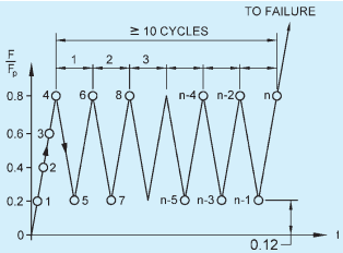
FIG. 19 PROCEDURE FOR THE LOAD TRANSFER TEST
B-3.3 Measurements and Observations
The following measurements and observations should be taken and recorded:
a) Longitudinal and transverse concrete strains on the side faces of the specimen in the region of maximum bursting effect under the upper and lower load at different times for increasing numbers of load cycles.
b) Formation, width and propagation of cracks on the side faces of the specimen, as mentioned above.
c) Visual inspection and/or measurement of deformation of anchorage components in contact with the concrete.
d) Location and mode of failure.
B-3.4 Requirements
Each specimen should meet the following requirements (see Fig. 20):
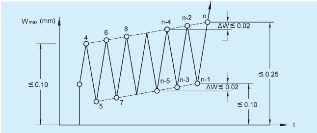
FIG. 20 REQUIREMENTS FOR CRACK WIDTHS
a) Crack width upon first attainment of upper force 0.8 (load point 4) should be .
b) Crack width upon last attainment of lower force 0.12 (load point n-1) should be ≤0.10 mm.
c) Crack width upon final attainment of upper force 0.8 (load point ) should be .
d) Readings of longitudinal and transverse strains should have stabilized during cyclic loading. The strains can be assumed to have stabilized if the increase of strain in last two load cycles
is less than 5 percent.
e) Readings of crack widths should have stabilized during cyclic loading. The crack widths can be assumed to have stabilized if the crack width does not increase by 0.02 mm in the last two load cycles.
f) The measured failure load shall meet each of the following requirements: