17.2.1 Design Sequence and Methods
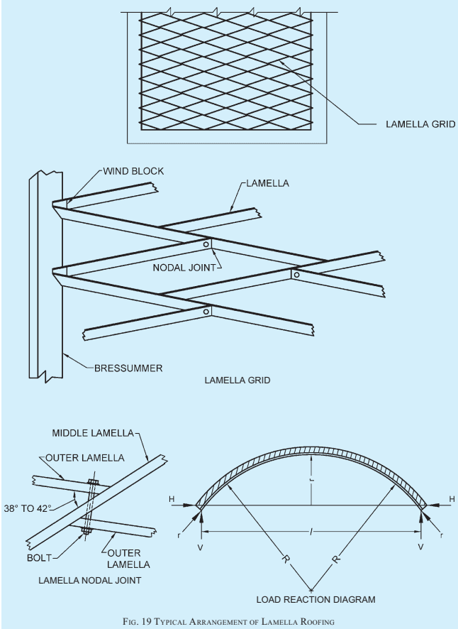
A lamella roof is essentially an arch (segmental, parabolic or elliptical) formed by a system of intersecting skewed arches, built up of relatively short members of small dimensional planks called 'lamellas'. The arch is designed as a two hinged arch with a depth equal to the depth of the individual lamella and a width equal to the span of the building of certain length. For design purposes, a unit length of the given span forming a single arch is considered loaded with the given loads. For the particular arch, curvature offers resultant outward suction on the roof to be less than its self weight to facilitate design and construction for economy. (This is possible only when the semi-angle of arch is less than 42∘ ).
Some design assumptions are:
a) Self weight of timber components (in particular species), namely lamella planks, roof boarding, wall plates, etc is assumed for the particular timber section.
b) Imposed loads as per Part 6 ‘Structural Design, Section 1 Loads, Forces and Effects’ of the Code for curved roofs where slope at springing point is greater than 10∘ . Take the reduced worked out values of imposed loads for actual design for timber components as per this Subsection.
c) Wind load is taken as per Part 6 ‘Structural Design, Section 1 Loads, Forces and Effects’ of the Code for structures with large openings, that is, openings larger than 20 percent of wall area (or as the case may be).
d) Stresses developed in curved lamella planks should not exceed the allowable safe stresses of timber species used.
e) Range of various sizes of timber planks for lamellas shall be as under:
-
Length — 1.0 m to 2.5 m
-
Section:
i) Thickness — 25 mm to 50 mm
ii) Width of uncurved plank — 100 mm to 250 mm
f) Limitations to be observed for spacing of lamellas over wall plate (or bressummer):
- i) For skew angle of 21∘ (diamond angle 42∘ ).
ii) For 2.5 m length of plank, spacing shall be 870 mm.
iii) For 1.0m length, spacing shall be 360 mm.
- i) For skew angle of 19∘ (diamond angle 38∘ ).
ii) For 2.5m length of plank, spacing shall be 800 mm.
iii) For 1.0 m length of plank, spacing shall be 320 mm.
g) Value of horizontal thrust, resultant thrust and maximum bending moment, are taken on per metre length of structure in case of transverse direction of arch.
h) Bending moment may be suitably reduced, if so desired by the designer, by applying stability factor if the ratio of the length of structure to the curved length of arch so warrants (as this ratio increases, the stability of the structure decreases).
j) The thrust in the skewed direction of arch, within one spacing of lamellas is shared by two lamella-lines in skewed direction.
k) More than one bolt (MS) shall be used for nodal joint. For design check of bolt against tension, half the value of thrust in skewed direction will be considered for calculations purposes in light of (j) [in case of stiff roof covering material (that is, CGI sheet, close boarding, etc) all lamella planks will be held jointly-behaving as a monolithic unit to a large extent and the actual stresses developed in bolt will be reduced resulting in lesser actual tension in bolts than the calculated design value].
17.2.1.1 Horizontal thrust
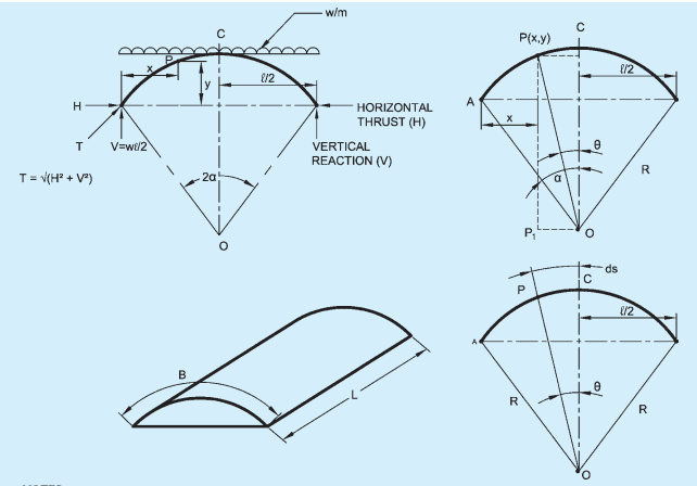
Any of the known methods for solving a statically indeterminate structure is used to evaluate horizontal thrust, bending moment, etc, to which a segmental arch will be subjected under the given condition of loadings. For 60∘ segmental arch, the radius of an arch will be equal to the span of the arch. Horizontal thrust can be calculated by the following two methods:
a) Method 1
Horizontal thrust (HB) per length of one bay (that is, distance between ‘tie-rod spacing’ or ‘column centres’):
17.2.1.2 Resultant thrust, T{1}
Due to horizontal thrust and the vertical reaction, resultant transverse thrust, in kg per metre length on the arch can be worked out:
17.2.1.3 Maximum bending moment
Bending moment at any point ‘P’ on arch making an angle of θ with the vertical line OC is, BM=μ−(H×y)
17.2.1.4 Spacing of lamellas
Lengthwise spacing of lamellas depends upon the angle of skew lamellas and the length of the planks used for lamellas (As a general guidance it may be stated that the angle enclosed between the intersecting skewed arches should not exceed 45∘ . An angle between 38∘ and 40∘ is always preferred.)
17.2.1.5 Design of lamella sizes
Net section of each of lamellas is assumed in curved profile conforming to the curvature of the roof surface.
Maximum BM=Ms over 600 mm spacing of lamella in the direction of skew angle, for example
17.2.1.6 Design of bolts for nodal joint
To avoid any possibility of hinge action with the use of bolts, it is imperative to adopt two or more bolts of smaller diameter and adequately spaced in accordance with the good practice [6-3A(9)].
Assume diameter of bolt ‘d’ in mm, and length of bolt in one plank ‘t’ mm, that is, thickness of middle lamella plank.
Area of contact of bolt with timber plank =d×tmm2
a) Check against crushing of timber at contact point of bolt — For the bolt to transmit load without crushing the timber fibres, the following condition shall be satisfied:
t×d× compressive stress perpendicular to grain for the timber species
17.2.1.7 Design of steel washer at joints
Area of steel plate =Atmm2
Stress perpendicular to grain of wood at the point of contact with steel plate washer =Z