22.1 Limit State of Collapse: Flexure
22.1.1 Assumptions
Design for the limit state of collapse in flexure shall be
Table 7 Values of Partial Safety Factor For Loads
(Clause 20.4.2)
| Sl No. | Load Combination | Limit State of Collapse | Limit States of Serviceability | ||||||
| DL(3) | IL(4) | WL(5) | P(6) | DL(7) | IL(8) | WL(9) | P(10) | ||
| i) | DL + IL + P | 1.5 | 1.5 | — | 1.0 | 1.0 | 1.0 | — | |
| ii) | DL + WL + P | — | 1.5 | 1.0 | 1.0 | — | 1.0 | ||
| iii) | DL + IL + WL + P | 1.2 | 1.2 | 1.2 | 1.0 | 1.0 | 0.8 | 0.8 | |
based on the assumptions given below:
a) Plane sections normal to the axis remain plane after bending.
b) The strain in the bonded reinforcement or bonded prestressing steel whether in tension or in compression is the same as that in the surrounding concrete.
c) The maximum strain in concrete at the outermost compression fibre is taken as 0.0035 in bending.
d) The relationship between the compressive stress distribution in concrete and the strain in concrete may be assumed to be rectangle, trapezoid, parabola or any other shape which results in prediction of strength in substantial agreement with the results of tests. An acceptable stress-strain curve is given in Fig. 3. For design purposes, the compressive strength of concrete in the structure shall be assumed to be 0.67 times the characteristic strength. The partial safety factor shall be applied in addition to this.
NOTE — For the stress-strain curve in Fig. 3, the design stress block parameters for rectangular section are as follows (see Fig. 4):
Area of stress block = 0.36 Depth of centre of compressive = 0.42 force from the extreme fibre in compression
where
characteristic compressive strength of concrete, and
= depth of neutral axis.
e) The tensile strength of the concrete is ignored.
f) The stresses in bonded prestressing tendons, whether initially tensioned or untensioned, and in additional reinforcement are derived from the representative stress-strain curve for the type of steel used given by the manufacturer or typical curves given in Fig. 5 for prestressing tendons and in Part 6 'Structural Design, Section 5 Concrete, Subsection 5A Plain and Reinforced Concrete' of the Code for reinforcement. For design purposes, the partial safety factor equal to 1.15 shall be applied. In addition, the tendon will have an initial prestrain due to prestress after all losses. For members with permanently unbonded internal or externally prestressed tendons, the deformation of the whole member shall be taken into account for calculating strain and stress in the tendon at ultimate condition. In the absence of rigorous analysis, the strain in unbonded tendon shall be assumed not to increase above the initial value due to prestress after all losses.
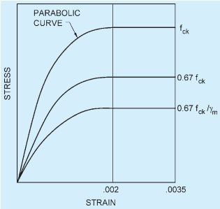
FIG. 3 STRESS STRAIN CURVE FOR CONCRETE
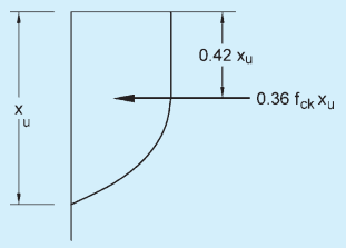
FIG. 4 STRESS BLOCK PARAMETERS
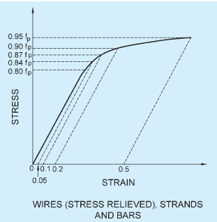
FIG. 5 REPRESENTATIVE STRESS STRAIN CURVES FOR PRESTRESSING STEEL
PART 6 STRUCTURAL DESIGN — SECTION 5 CONCRETE: 5B PRESTRESSED CONCRETE
22.1.2 Design Formulae
In the absence of an analysis based on the assumptions given in 22.1.1, the moment of resistance of rectangular sections and flanged sections in which the neutral axis lies within the flange may be obtained by the procedure given in Annex C.
For flanged sections in which the neutral axis lies outside the flange, the moment of resistance shall be determined using assumptions given in 22.1.1.
22.2 Limit State of Collapse: Compression
Prestressed concrete compression members in framed structures, where the mean stress in the concrete section imposed by tendons is less than , may be analysed as reinforced concrete compression members in accordance with Part 6 ‘Structural Design, Section 5 Concrete, Subsection 5A Plain and Reinforced Concrete’ of the Code, in other cases specialist literature may be referred to.
22.3 Limit State of Collapse: Tension
Tensile strength of the tension members shall be used on the design strength (0.87 times characteristic strength of prestressing tendons) and the strength developed by any additional reinforcement. The additional reinforcement may usually be assumed to be acting at its design stress (0.87 times characteristic strength of reinforcement); in special cases it may be necessary to check the stress in the reinforcement using strain compatibility.