21.1 General
All structures may be analysed by the linear elastic theory to calculate internal actions produced by design loads. In-lieu of rigorous elastic analysis, a simplified analysis as given in 21.4 for frames and as given in 21.5 for continuous beams may be adopted.
21.2 Effective Span
Unless otherwise specified, the effective span of a member shall be as follows:
a) Simply supported beam or slab — The effective span of a member that is not built integrally with its supports shall be taken as clear span plus the effective depth of slab or beam or centre-to-centre of supports, whichever is less.
b) Continuous beam or slab — In the case of continuous beam or slab, if the width of the support is less than 1/12 of the clear span, the effective span shall be as given in 21.2 (a). If the supports are wider than 1/12 of the clear
span or 600 mm, whichever is less, the effective span shall be taken as under :
-
For end span with one end fixed and the other continuous or for intermediate spans, the effective span shall be the clear span between supports;
-
For end span with one end free and the other continuous, the effective span shall be equal to the clear span plus half the effective depth of the beam or slab or the clear span plus half the width of the discontinuous support, whichever is less;
-
In the case of spans with roller or rocker bearings, the effective span shall always be the distance between the centres of bearings.
c) Cantilever — The effective length of a cantilever shall be taken as its length to the face of the support plus half the effective depth except where it forms the end of a continuous beam where the length to the centre of support shall be taken.
d) Frames — In the analysis of a continuous frame, centre-to-centre distance shall be used.
21.3 Stiffness
21.3.1 Relative Stiffness
The relative stiffness of the members may be based on the moment of inertia of the section determined on the basis of any one of the following definitions:
a) Gross section — The cross-section of the member ignoring reinforcement;
b) Transformed section — The concrete cross-section plus the area of reinforcement transformed on the basis of modular ratio (see B-1.3); or
c) Cracked section — The area of concrete in compression plus the area of reinforcement transformed on the basis of modular ratio.
The assumptions made shall be consistent for all the members of the structure throughout any analysis.
21.3.2 For deflection calculations, appropriate values of moment of inertia as specified in Annex C should be used.
21.4 Structural Frames
The simplifying assumptions as given in 21.4.1 to 21.4.3 may be used in the analysis of frames.
21.4.1 Arrangement of Imposed Load
a) Consideration may be limited to combinations of,
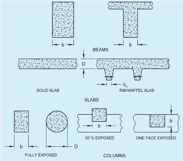
| Fire Resistance | Minimum Beam Width | Rib Width of Slabs | Minimum Thickness of Floors | Minimum Column Dimension (b or D) | Minimum Wall Thickness | ||||
| Fully Exposed | 50% Exposed | One Face Exposed | p<0.4% | 0.4% ≤ p ≤ 1% | p>1% | ||||
| h(1) | b mm(2) | mm(3) | |||||||
21.5 Moment and Shear Coefficients for Continuous Beams
21.5.1 Unless more exact estimates are made, for beams of uniform cross-section which support substantially uniformly distributed loads over three or more spans which do not differ by more than 15 percent of the longest, the bending moments and shear forces used in design may be obtained using the coefficients given in Table 12 and Table 13, respectively.
For moments at supports where two unequal spans meet or in case where the spans are not equally loaded, the average of the two values for the negative moment at the support may be taken for design.
| Sl No. | Type of Load | Span Moments | Support Moments | ||
| Near Middle of End Span(3) | At Middle of Interior Span(4) | At Support Next to the End Support(5) | At Other Interior Supports(6) | ||
| (1) | (2) | ||||
| i) | Dead load and imposed load (fixed) | ||||
21.6 Critical Sections for Moment and Shear
21.6.1 For monolithic construction, the moments computed at the face of the supports shall be used in the design of the members at those section. For non-monolithic construction the design of the member shall be done keeping in view 21.2.
21.6.2 Critical Section for Shear
The shears computed at the face of the support shall be used in the design of the member at that section except as in 21.6.2.1.
21.6.2.1 When the reaction in the direction of the applied shear introduces compression into the end region of the member, sections located at a distance less than d from the face of the support may be designed for the same shear as that computed at distance d (see Fig. 2).
NOTE — The above clauses are applicable for beams generally carrying uniformly distributed load or where the principal load is located farther than 2d from the face of the support.
21.7 Redistribution of Moments
Redistribution of moments may be done in accordance with 36.1.1 for limit state method and in accordance with B-1.2 for working stress method. However, where
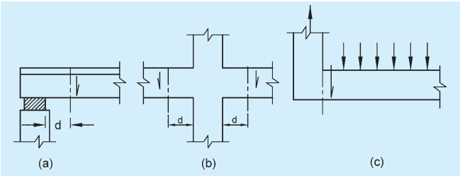
FIG. 2 TYPICAL SUPPORT CONDITIONS FOR LOCATING FACTORED SHEAR FORCE
simplified analysis using coefficients is adopted, redistribution of moments shall not be done.