7.1 General
Nail jointed timber construction is suitable for light and medium timber framings (trusses, etc) up to spans. With the facilities of readily available materials and simpler workmanship in mono-chord and split-chord constructions, this type of fabrication has a large scope. Preboring of nail-jointed timber construction is desirable and shall be done in accordance with good practice as in, 6.2.2 and Table 3 of good practice [6-3A(7)].
7.2 Dimensions of Members
The dimension of an individual piece of timber (that is any single member) shall be within the range given below:
a) The minimum thickness of the main members
in mono-chord construction shall be .
b) The minimum thickness of an individual piece of members in split-chord construction shall be 20 mm for web members and 25 mm for chord members.
c) The space between two adjacent pieces of timber shall be restricted to a maximum of 3 times the thickness of the individual piece of timber of the chord member. In case of web members, it may be greater for joining facilities.
7.3 No lengthening joint shall preferably be located at a panel point. Generally not more than two, but preferably one, lengthening joint shall be permitted between the two panel points of the members.
7.4 Specification and Diameter of Nails
7.4.1 The nails used for timber joints shall conform to Part 5 ‘Building Materials’ of the Code. The nails shall be diamond pointed.
7.4.2 The diameter of nail shall be within the limits of one-eleventh to one-sixth of the least thickness of members being connected.
7.4.3 Where the nails are exposed to be saline conditions, common wire nails shall be galvanized.
7.5 Arrangement of Nails in the Joints
The end distances, edge distances and spacings of nails in a nailed joint should be such as to avoid undue splitting of the wood and shall not be less than those given in 7.5.1 and 7.5.2.
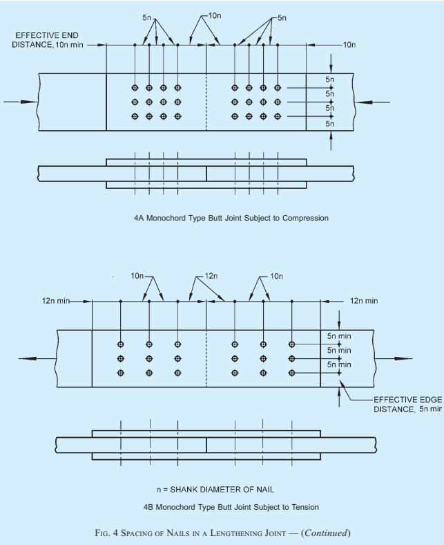
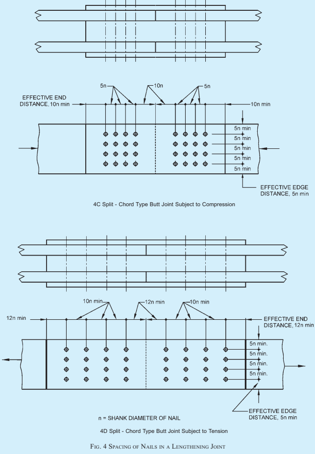
7.5.1 Lengthening Joints
The requirement of spacing of nails in a lengthening joint shall be as given in Table 14 (see also Fig. 4):
| Sl No. | Spacing of Nails | Type of Stress in the Joint | Requirement Min |
| (1) | (2) | (3) | (4) |
| i) | End distance | Tension | 12 n |
| Compression | 10 n | ||
| ii) | In direction of grain | Tension | 10 n |
| Compression | 5 n | ||
| iii) | Edge distance | — | 5 n |
| iv) | Between row of nails perpendicular to the grain | — | 5 n |
| NOTES | |||
| 1 n is shank diameter of nails. | |||
| 2 The 5n distance between rows perpendicular to the grain may be increased subject to the availability of width of the member keeping edge distance constant. | |||
PART 6 STRUCTURAL DESIGN — SECTION 3 TIMBER AND BAMBOO: 3A TIMBER
PART 6 STRUCTURAL DESIGN — SECTION 3 TIMBER AND BAMBOO: 3A TIMBER
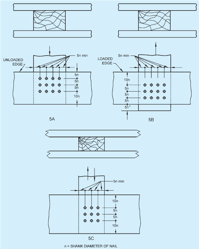
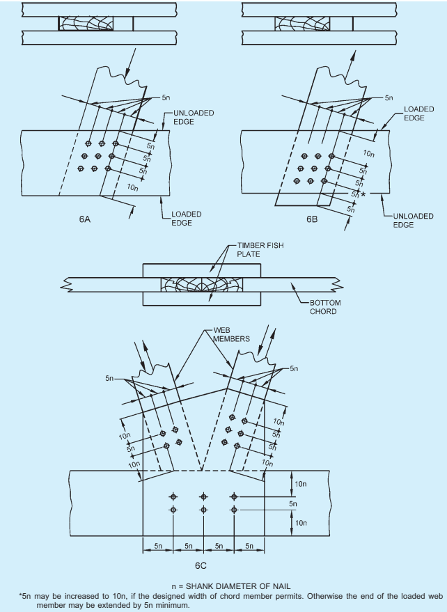
7.5.2 Node Joints
The requirement for spacing of nails in node joints shall be as specified in Fig. 5 where the members are at right
angle and as in Fig. 6 where the members are inclined to one another at angles other than and subjected to either pure compression or pure tension.
7.6 Penetration of Nails
7.6.1 For a lap joint when the nails are driven from the side of the thinner member, the length of penetration of nails in the thicker member shall be one and a half times the thickness of the thinner member subject to maximum of the thickness of the thicker member.
7.6.2 For butt joints the nails shall be driven through the entire thickness of the joint.
7.7 Design Considerations
7.7.1 Where a number of nails are used in a joint, the allowable load in lateral resistance shall be the sum of the allowable loads for the individual nails, provided that the centroid of the group of these nails lies on the axis of the member and the spacings conform to 7.5. Where a large number of nails are to be provided at a joint, they should be so arranged that there are more of rows rather than more number of nails in a row.
7.7.2 Nails shall, as far as practicable, be arranged so that the line of force in a member passes through the centroid of the group of nails. Where this is not practicable, allowance shall be made for any eccentricity in computing the maximum load on the fixing nails as well as the loads and bending moment in the member.
7.7.3 Adjacent nails shall preferably be driven from opposite faces, that is, the nails are driven alternatively from either face of joint.
7.7.4 For a rigid joint, a minimum of 2 nails for nodal joints and 4 nails for lengthening joint shall be driven.
7.7.5 Two nails in a horizontal row are better than using the same number of nails in a vertical row.
7.7.6 The permissible lateral strength (in double shear) of mild steel common wire for different species of timber shall be as per 4.3.
7.8 Special Consideration in Nail-Jointed Truss Construction
7.8.1 The initial upward camber provided at the centre of the lower chord of nail-jointed timber trusses shall be not less than 1/200 of the effective span for timber structures using seasoned wood and 1/100 for unseasoned or partially seasoned wood.
7.8.2 The total combined thickness of the gusset or splice plates on either side of the joint in a mono-chord type construction shall not be less than one and a half times the thickness of the main members subject to a minimum thickness of of individual gusset plate.
NOTES
1 The allowable load or lateral strength values of nails shall be those as given in Table 2 and Table 3.
2 The strength data for joints given in the Subsection apply to gusset or splice or fish plates of solid wood; however, materials other than solid wood may be used for gusset when field tests are made and their strength requirements have been established.
7.8.3 The total combined thickness of all spacer blocks or plates or both including outer splice plates, at any joint in a split-chord type construction shall not be less than one and a half times the total thickness of all the main members at that joint.
7.9 Fabrication
The fabrication of nail-jointed timber construction shall be done in accordance with good practice [6-3A(7)].