Construction of the following types of load bearing and non-load bearing masonry walls shall be carried out in accordance with good practice [6-4(4)]:
a) Brickwork,
b) Stone masonry,
c) Hollow concrete block masonry,
d) Gypsum partition blocks,
e) Autoclaved cellular concrete block masonry, and
f) Lightweight concrete block masonry.
6.1.2 Construction of Buildings in Seismic Zones
Special features of construction for earthquake resistant masonry buildings in Seismic Zones II, III, IV and V shall be applicable according to 8.
6.2 Minimum Thickness of Walls from Consideration other than Structural
Thickness of walls determined from consideration of strength and stability may not always be adequate in respect of other requirements, such as resistance to fire, thermal insulation, sound insulation and resistance to damp penetration for which reference may be made to the appropriate Parts/Sections of the Code, and thickness suitably increased, where found necessary.
6.3Workmanship
6.3.1 General
Workmanship has considerable effect on strength of
masonry and bad workmanship may reduce the strength of brick masonry to as low as half the intended strength. The basic compressive stress values for masonry as given in Table 9 holds good for commercially obtainable standards of workmanship with reasonable degree of supervision.
6.3.2 Bedding of Masonry Units
Masonry units shall be laid on a full bed of mortar with frog, if any, upward such that cross-joints and wall joints are completely filled with mortar. Masonry units which are moved after initial placement shall be re-laid in fresh mortar, discarding the disturbed mortar.
6.3.3 Bond
Cross-joints in any course of one brick thick masonry wall shall be not less than one-fourth of a masonry unit in horizontal direction from the cross-joints in the course below. In masonry walls more than one brick in thickness, bonding through the thickness of wall shall be provided by either header units or by other equivalent means in accordance with good practice [6-4(5)].
6.3.4 Verticality and Alignment
All masonry shall be built true and plumb within the tolerances prescribed below; care shall be taken to keep the perpends properly aligned:
a) Deviation from vertical within a storey shall not exceed 6 mm per 3 m height.
b) Deviation in verticality in total height of any wall of a building more than one storey in height shall not exceed 12.5 mm.
c) Deviation from position shown on plan of any brickwork shall not exceed 12.5 mm.
d) Relative displacement between load bearing walls in adjacent storeys intended to be in vertical alignment shall not exceed 6 mm.
e) Deviation of bed-joint from horizontal in a length of 12 m shall not exceed 6 mm subject to a maximum deviation of 12 mm.
f) Deviation from the specified thickness of bed joints, cross-joints and perends shall not exceed one-fifth of the specified thickness.
NOTE — These tolerances have been specified from the point of view of their effect on the strength of masonry. The permissible stress recommended in 5.3 may be considered applicable only, if these tolerances are adhered to.
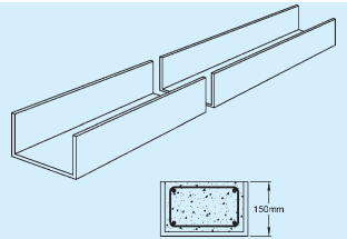
6.4 Joints to Control Deformation and Cracking
Special provision shall be made to control or isolate thermal and other movements so that damage to the fabric of the building is avoided and its structural sufficiency preserved. Design and installation of joints shall be done according to the appropriate
recommendations in accordance with good practice [6-4(6)].
6.6Corbelling
6.6.1 Where corbelling is required for the support of some structural element, maximum projection of masonry unit should not exceed one-half of the height of the unit or one-half of the built-in part of the unit and the maximum horizontal projection of the corbel should not exceed one-third of the wall thickness.
6.6.2 The load per unit length on a corbel shall not be greater than half of the load per unit length on the wall above the corbel. The load on the wall above the corbel, together with four times the load on the corbel, shall not cause the average stress in the supporting wall or leaf to exceed the permissible stresses given in 5.4.
6.6.3 It is preferable to adopt header courses in the corbelled portion of masonry from considerations of economy and stability.
7 REINFORCED BRICK AND REINFORCED BRICK CONCRETE FLOORS AND ROOFS
The construction and design of reinforced brick and reinforced brick concrete floors and roof shall be in accordance with good practices [6-4(7)].
8 SPECIAL CONSIDERATION FROM EARTHQUAKE POINT OF VIEW
8.0 Special features of design and construction for earthquake resistant masonry buildings are given in 8.2 to 8.8.2. However, special features of design and construction for improving earthquake resistance of low strength masonry buildings is covered in 9.
8.1 For the purpose of 8 and 9, the definitions given below shall apply in addition to those given in 2.
8.1.1 Separation Section — A gap of specified width
between adjacent buildings or parts of the same building either left uncovered or covered suitably to permit movement in order to avoid pounding due to earthquake.
8.1.1.1 Crumple section — The separation gap filled with appropriate material that crumples or factures in the event of an earthquake.
8.1.2 Centre of Rigidity — The point in a structure where application of lateral force produces equal deflections of its components at any level in any particular direction.
8.1.3 Shear Wall — A wall designed to resist lateral force in the own plane. Braced frames, subjected primarily to axial stresses, shall be considered as shear walls for the purpose of this definition.
8.1.4 Space Frame — A three-dimensional structural system comprised of interconnected members, without shear or bearing walls, so that to function as a complete self-contained unit with or without the aid of horizontal diaphragms or floor bracing systems.
8.1.4.1 Vertical load carrying frame — A space frame designed to carry all the vertical loads, the horizontal loads being resisted by shear walls.
8.1.4.2 Moment resistant frame — A space frame capable of carrying all vertical and horizontal loads, by developing bending moments in the members and at joints.
8.1.4.3 Moment resistant frame with shear walls — A space frame with moment resistant joints and strengthened by shear walls to assist in carrying horizontal loads.
8.1.5 Box System — A bearing wall structure without a space frame, the horizontal forces being resisted by the walls that act as shear walls.
8.1.6 Band — A reinforced concrete or reinforced brick runner provided in the walls to tie them together and to impart horizontal bending strength in them.
NOTE — For low strength masonry buildings, wooden runners may also be used as runner.
8.1.7 Seismic Zone and Seismic Coefficient — The Seismic Zones II to IV as classified in 5 of Part 6 'Structural Design, Section 1 Loads, Forces and Effects' of the Code and corresponding basic seismic coefficient αo as specified in 3.4 of good practice [6-4(8)].
8.1.8 Design Horizontal Seismic Coefficient — The value of horizontal seismic coefficient Ah computed taking into account the soil-foundation system and the importance factor as specified in 6.4 of good practice [6-4(9)].
8.1.9 Concrete Grades — 28 day compressive strength
of concrete cubes of 150mm size, in MPa; for example, for Grade M20 as per good practice[6-4(10)], the characteristic compressive strength equals to 20MPa.
8.1.10 Zone Factor (Z) — It is a factor to obtain the design spectrum depending on the perceived maximum seismic risk characterized by maximum considered earthquake (MCE) in the zone in which the structure is located.
8.2General Principles
The general principles given in 8.2.1 to 8.2.9 shall be observed in construction of earthquake resistant buildings.
8.2.1 Lightness
Since the earthquake force is a function of mass, the weight of the building shall be as minimum as possible, consistent with structural safety and functional requirements. Roofs and upper storeys of buildings, in particular, should be designed as light as possible.
8.2.2 Continuity of Construction
8.2.2.1 As far as possible, the parts of the building should be tied together in such a manner that the building acts as one unit.
8.2.2.2 For parts of buildings between separation or crumple sections to expansion joints, floor slabs shall be continuous throughout as far as possible. Concrete slabs shall be rigidly connected or integrally cast with the support beams.
8.2.2.3 Additions to the structures shall be accompanied by the provision of separation or crumple sections between the new and the existing structures as far as possible, unless positive measures are taken to establish continuity between the existing and the new construction.
8.2.2.4 Alteration to the building structure shall be done by maintaining its structural stability by ensuring proper load path.
8.2.3 Projecting and Suspended Parts
8.2.3.1 Projecting parts shall be avoided as far as possible. If the projecting parts cannot be avoided, they shall be properly reinforced and firmly tied to the main structure, and their design shall be in accordance with good practice [6-4(8)].
8.2.3.2 Ceiling plaster shall preferably be avoided. When it is unavoidable, the plaster shall be as thin as possible.
8.2.3.3 Suspended ceiling shall be avoided as far as possible. Where provided they shall be light, adequately framed and secured to which electrical fixtures shall be fully secured.
8.2.4 Building Configuration
8.2.4.1 In order to minimise torsion and stress concentration, provisions given in 8.2.4.2 to 8.2.4.4 should be complied with as relevant.
8.2.4.2 The building should have a simple rectangular plan and be symmetrical both with respect to mass and rigidity so that the centre of mass and rigidity of the building coincide with each other in which case no separation sections other than expansion joints are necessary. For provision of expansion joints reference may be made to good practice [6-4(6)].
8.2.4.3 If symmetry of the structure is not possible in plan, elevation or mass, provision shall be made for torsional and other effects due to earthquake forces in the structural design or the parts of different rigidities may be separated through crumple sections. The length of such building between separation sections shall not preferably exceed three times the width.
NOTE — As an alternative to separation section to reduce torsional moments, the centre of rigidity of the building may be brought close or coincident to the centre of mass by adjusting the locations and/or sizes of columns and walls.
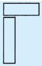
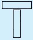
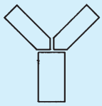
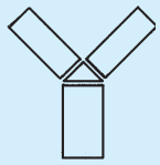
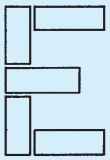
8.2.4.4 Buildings having plans with shapes like L, T, E and Y shall preferably be separated into rectangular parts by providing separation sections at appropriate places. Typical examples are shown in Fig. 15.
NOTES
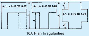
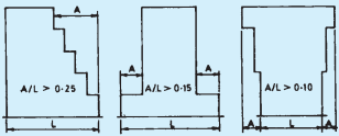
1 The buildings with small lengths of projections forming L, T, E or Y shapes need not be provided with separation section. In each cases the length of the projection may not exceed 15 to 20 percent of the total dimension of the building in the direction of the projection (see Fig. 16).
2 For buildings with minor asymmetry in plan and elevation, separation sections may be omitted.
8.2.5 Strength in Various Directions
The structure shall be designed to have adequate strength against earthquake effects along both the horizontal axes. The design shall also be safe considering the reversible nature of earthquake forces.
8.2.6 Foundations
The structure shall not be founded on such soils which shall subside or liquefy during an earthquake, resulting in large differential settlements (see also 8.3.3.3).
8.2.7 Ductility
The main structural elements and their connection shall be designed to have a ductile failure. This shall enable the structure to absorb energy during earthquakes to avoid sudden collapse of the structure. Providing reinforcing steel in masonry at critical sections, as specified in this Section shall not only increase strength and stability but also ductility. The details for achieving ductility in reinforced concrete structures is given in good practice [6-4(11)].
L - SHAPE
T-SHAPE
Y-SHAPE
Y-SHAPE
E-SHAPE
FIG. 15 TYPICAL SHAPES OF BUILDING WITH SEPARATION SECTIONS
16B Vertical Irregularities
FIG. 16 PLAN AND VERTICAL IRREGULARITIES
PART 6 STRUCTURAL DESIGN — SECTION 4 MASONRY
8.2.8 Damage to Non-Structural Parts
Suitable details shall be worked out to connect the non-structural parts with the structural framing so that the deformation of the structural frame leads to minimum damage of the non-structural elements.
8.2.9 Fire Safety
Fire frequently follows an earthquake and therefore, buildings shall be constructed to make them fire resistant in accordance with the provisions of Part 4 ‘Fire and Life Safety’ of the Code for fire safety.
8.3Special Construction Features
8.3.1 Separation of Adjoining Structures
8.3.1.1 Separation of adjoining structures or parts of the same structure is required for structures having different total heights or storey heights and different dynamic characteristics. This is to avoid collision during an earthquake.
8.3.1.2 Minimum width of separation gaps as mentioned in 8.3.1.1, shall be as specified in Table 13. The design seismic coefficient to be used shall be in accordance with 5 of Part 6 'Structural Design, Section 1 Loads, Forces and Effects' of the Code.
8.3.1.3 Where separation is necessary, a complete separation of the parts shall be made except below the plinth level. The plinth beams, foundation beams and footings may be continuous. Where separation sections
17A BRICK WALL
17C METAL SIDING INDUSTRIAL WORK
Table 13Gap Width for Adjoining Structures (Clause 8.3.1.2)
Sl.No.
Buildings Categories for Earthquake Resisting Features
Gap Width per Storey for Adjoining Masonry Building
mm
(1)
(2)
(3)
i)
Frames with shear walls
15
ii)
Category B1)
10
iii)
Category C1)
10
iv)
Category D1)
15
v)
Category E1)
20
1) See Table 14.
NOTE — Minimum total gap shall be 25 mm. For any other value of Ah the gap width shall be determined proportionately.
are provided in a long building, they shall take care of movement owing to temperature changes also.
8.3.2 Separation or Crumple Section
8.3.2.1 In case of framed construction, members shall be duplicated on either side of the separation or crumple section. As an alternative, in certain cases, such duplication may not be provided, if the portions on either side can act as cantilevers to take the weight of the building and other relevant loads.
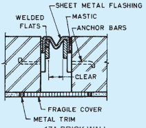
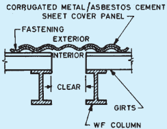
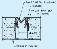
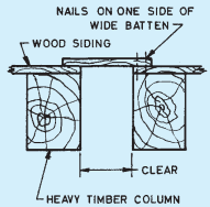
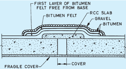
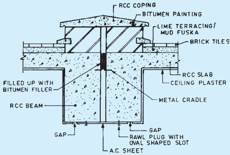
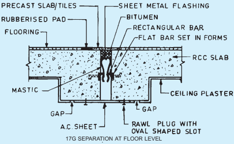
8.3.2.2 Typical details of separation and crumple sections are shown in Fig. 17. For other types of joint details, reference may be made to good practice [6-4(6)].
17B CONCRETE WALLS
17D WOOD SHEATHING INDUSTRIAL WORK
FIG. 17 TYPICAL DETAILS OF SEPARATION OR CRUMPLE SECTION (CONTINUED)
17E RCC SLAB ON ROOF SURFACE
17F SEPARATION JOINT DETAILS AT ROOF
NOTE — Fragile cover may consist of asbestos cement sheet, particle board and like.
FIG. 17 TYPICAL DETAILS OF SEPARATION OR CRUMPLE SECTION
PART 6 STRUCTURAL DESIGN — SECTION 4 MASONRY
8.3.3 Foundations
8.3.3.1 For the design of foundations, the provisions of Part 6 ‘Structural Design, Section 1 Loads, Forces and Effects’ and Section 2 ‘Soils and Foundation’ of the Code shall generally be followed.
8.3.3.2 The subgrade below the entire area of the building shall preferably be of the same type of the soil. Wherever this is not possible, a suitably located separation or crumple section shall be provided.
8.3.3.3 Loose fine sand, soft silt and expansive clays should be avoided. If unavoidable, the building shall rest either on a rigid raft foundation or on piles taken to a firm stratum. However, for light constructions the following measures may be taken to improve the soil on which the foundation of the building may rest:
a) Sand piling, and
b) Soil stabilization.
8.3.3.4 Isolated footings for columns
All the individual footings or pile caps where used in Type III Soft soils {Table 1 of good practice [6-4(9)]}, shall be connected by reinforced concrete ties at least in two directions approximately at right angles to each other. For buildings with no basement, the ties may be placed at or below the plinth level and for buildings with basement they may be placed at the level of basement floor. They shall need to be designed to carry the load of the panel walls also.
NOTE — The ties may not be necessary where structural floor connects the columns at or below the plinth level.
8.3.3.4.1 Where ties are used, their sections shall be designed to carry in tension as well as in compression, an axial load not less than the earthquake force in the direction the tie acting on the heavier of the columns connected, but the sections shall not be less than 200mm×200mm with M20 concrete reinforced with 4 bars of 12 mm diameter plain mild steel bars or 10 mm diameter high strength deformed bars, one at each corner, bound by 8 mm diameter stirrups not more than 150 mm apart.
NOTE — In working out the buckling strength of ties, the lateral support provided by the soil may be taken into account. Calculations show that for such buried ties, lateral buckling is not a problem and the full section of the tie may be taken effective as a short column.
8.3.4 Roofs and Floors
8.3.4.1 Flat roof or floor shall not preferably be made of tiles of ordinary bricks supported on steel, timber or reinforced concrete joists, nor they shall be of a type which in the event of an earthquake is likely to be loosened and parts or all of which may fall. If this type of construction cannot be avoided, the joists should be blocked at ends and bridged at intervals such that their spacing is not altered during an earthquake.
8.3.4.1.1 For pitched roofs, corrugated iron or asbestos sheets shall be used in preference to country, Allahabad or Mangalore tiles or other loose roofing units. All roofing materials shall be properly tied to the supporting members. Heavy roofing materials shall generally be avoided.
8.3.4.2 Pent roofs
8.3.4.2.1 All roof trusses shall be supported on reinforced concrete or reinforced brick band (see 8.6.4.3). The holding down bolts shall have adequate size and length as required for earthquake forces in accordance with 5 of Part 6 'Structural Design, Section 1 Loads, Forces and Effects' of the Code.
Where a trussed roof adjoins a masonry gable, the ends of the purlins shall be carried on and secured to a plate or bearer which shall be adequately bolted to reinforced concrete or reinforced brick band at the top of gable end masonry (see 8.6.4.4).
NOTE — Hipped roof in general have shown better structural behaviour during earthquakes than gable ended roofs.
8.3.4.2.2 At tie level all the trusses and the gable end shall be provided with diagonal braces in plan so as to transmit the lateral shear due to earthquake force to the gable walls acting as shear walls at the ends as specified in 8.6.4.
8.3.4.3 Jack arches
Jack arched roofs or floors, where used shall be provided with mild steel ties in all spans along with diagonal braces in plan to ensure diaphragms actions.
8.3.5 Staircases
8.3.5.1 The inter-connection of the stairs with the adjacent floors should be appropriately treated by providing sliding joints at the stairs to eliminate their bracing effect on the floors. Large stair halls shall preferably be separated from the rest of the building by means of separation or crumple sections.
8.3.5.2 Three types of stair construction may be adopted as described below:
a) Separated staircases — One end of the staircase rests on a wall and the other end is carried by columns and beams which have no
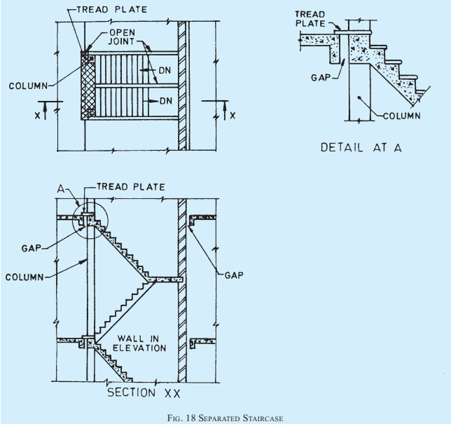
connection with the floors. The gap at the vertical joints between the floor and the staircase may be covered either with a tread plate attached to one side of the joint and sliding on the other side, or covered with some appropriate material which could crumple or fracture during an earthquake without causing structural damage. The supporting members, columns or walls, are isolated from the surrounding floors by means of separation or crumple sections. A typical example is shown in Fig. 18.
as mentioned in respect of separated staircases, shall not be necessary.
The two walls mentioned above, enclosing the staircase, shall extend through the entire height of the stairs and to the building foundations.
c) Staircases with sliding joints — In case it is not possible to provide rigid walls around stair openings for built-in staircase or to adopt the separated staircases, the staircases shall have sliding joints so that they shall not act as diagonal bracing.
b) Built-in staircase — When stairs are built monolithically with floors, they can be protected against damage by providing rigid walls at the stair opening. An arrangement, in which the staircase is enclosed by two walls, is given in Fig. 19. In such cases, the joints,
8.4Types of Construction
8.4.1 The types of construction usually adopted in buildings are as follows:
a) Framed construction; and
b) Box type construction.
PART 6 STRUCTURAL DESIGN — SECTION 4 MASONRY
8.4.2 Framed Construction
This type of construction is suitable for multi-storied and industrial buildings as described in 8.4.2.1 and 8.4.2.2.
8.4.2.1 Vertical load carrying frame construction
This type of construction consists of frames with flexible (hinged) joints and bracing members. Steel multi-storied building or industrial frames and timber construction usually are of this type.
8.4.2.1.1 Such buildings shall be adequately strengthened against lateral forces by shear walls and/or other bracing systems in plan, elevation and sections such that earthquake forces shall be resisted by them in any direction.
8.4.2.2 Moment resistant frames with shear walls
The frames may be of reinforced concrete or steel with
semi-rigid or rigid joints. The walls are rigid capable of acting as shear walls and may be of reinforced concrete or of brickwork reinforced or unreinforced bounded by framing members through shear connectors.
8.4.2.2.1 The frame and wall combinations shall be designed to carry the total lateral force due to earthquake acting on the building. The frame acting alone shall be designed to resist at least 25 percent of the total lateral force.
8.4.2.2.2 The shear walls shall preferably be distributed evenly over the whole building. When concentrated at one location, forming what is called a rigid core in the building, the design shall be checked for torsional effects and the shear connection between the core and the floors conservatively designed for the total shear transfer.
8.4.2.2.3 The shear walls should extend from the foundation either to the top of the building or to a lesser height as required from design consideration. In design, the interaction between frame and the shear walls should be considered properly to satisfy compatibility and equilibrium conditions.
NOTE — Studies show that shear walls of height about 85 percent of total height of building are advantageous.
8.4.3 Box Type Construction
This type of construction consists of prefabricated or in-situ masonry, concrete or reinforced concrete walls along both the axes of the building. The walls support vertical loads and also act as shear walls for horizontal loads acting in any direction. All traditional masonry construction falls under this category. In prefabricated construction attention shall be paid to the connection between wall panels so that transfer of shear between them is ensured.
8.5Categories of Buildings
8.5.1 For the purpose of specifying the earthquake resisting features in masonry and wooden buildings, the buildings have been categorized in four categories B to E based on the seismic zone and the importance of the building I,
where
I= Importance factor applicable to the building {as per good practice [6-4(9)]}.
8.5.1.1 The building categories are given in Table 14.
Table 14Building Categories for Earthquake Resisting Features (Clause 8.5.1.1)
SI No.
Importance Factor
Seismic Zone
II(3)
III(4)
IV(5)
V(6)
i)
1.0
B
C
D
E
ii)
1.5
C
D
E
E
NOTE — Category A is now defunct as Seismic Zone I does not exist any more.
8.6Masonry Construction with Rectangular Masonry Units
8.6.1 The design and construction of masonry walls using rectangular masonry units in general shall be governed by 3 to 7 of this Section and good practice [6-4(5)].
8.6.1.1 Masonry units
8.6.1.1.1 Well burnt bricks conforming to accepted standard [6−4(12)] or solid concrete blocks conforming to accepted standard [6−4(13)] and having a crushing strength not less than 3.5 MPa shall be used. The strength of masonry unit required shall depend upon
number of storeys and thickness of walls (see 3 to 6).
8.6.1.1.2 Squared stone masonry, stone block masonry or hollow concrete block masonry, as specified in the good practice [6-4(14)] of adequate strength, may also be used.
8.6.1.2 Mortar
8.6.1.2.1 Mortars, such as those given in Table 15 or of equivalent specification, shall preferably be used for masonry construction for various categories of buildings.
8.6.1.2.2 Where steel reinforcing bars are provided in masonry, the bars shall be embedded with adequate cover in cement sand mortar not leaner than 1 : 3 (minimum clear cover 10 mm) or in cement concrete of grade M20 (minimum clear cover 15 mm or bar diameter whichever is more), so as to achieve good bond and corrosion resistance.
8.6.3Openings in Bearing Walls
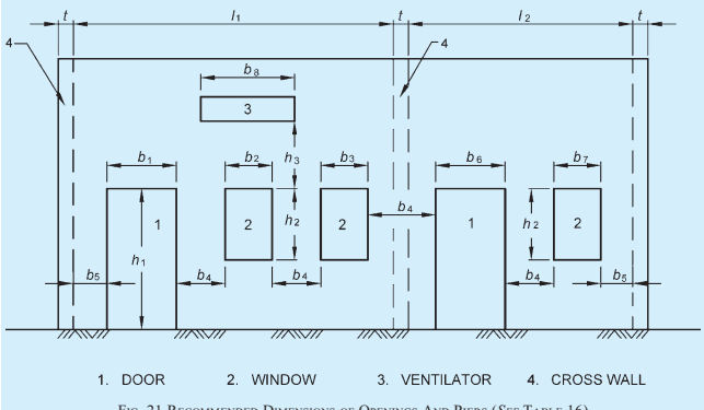
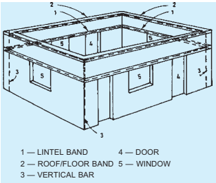
8.6.3.1 Door and window openings in walls reduce their lateral load resistance and hence, should preferably be small and more centrally located. The guidelines on the size and position of opening are given in Table 16 and Fig. 21.
Table 16Size and Position of Openings in Bearing Walls (Clause 8.6.3.1)
Sl No.
Position of Opening
Details of Opening for Building Category
B (3)
C (4)
D and E (5)
(1)
(2)
i)
Distance b5 from the inside corner of outside wall, mm, Min
0
230
450
ii)
For total length of openings, the ratio (b1+b2+b3)/l1 or (b6+b7)/l2 shall not exceed,
a) one-storeyed building
0.60
0.55
0.50
b) two-storeyed building
0.50
0.46
0.42
c) 3 or 4 storeyed building
0.42
0.37
0.33
iii)
Pier width between consecutive openings b4 , mm, Min
340
450
560
iv)
Vertical distance between two openings one above the other h3 , mm, Min
600
600
600
v)
Width of opening of ventilator b8 , mm, Max
900
900
900
NOTE — Four storeys buildings not allowed in Category E.
8.6.3.2 Openings in any storey shall preferably have their top at the same level so that a continuous band could be provided over them, including the lintels throughout the building.
FIG. 21 RECOMMENDED DIMENSIONS OF OPENINGS AND PIERS (SEE TABLE 16)
2 — ROOF/FLOOR BAND 5 — WINDOW
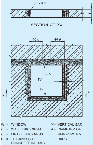
8.6.3.3 Where openings do not comply with the guidelines of Table 15, they should be strengthened by providing reinforced concrete or reinforcing the brickwork, as shown in Fig. 22 with high strength deformed (HSD) bars of 8 mm diameter but the quantity of steel shall be increased at the jambs to comply with 8.6.4.9, if so required.
FIG. 22 STRENGTHENING MASONRY AROUND OPENINGS
8.6.3.4 If a window or ventilator is to be projected out, the projection shall be in reinforced masonry or concrete and well anchored.
8.6.3.5 If an opening is tall from bottom to almost top of a storey, thus dividing the wall into two portions, these portions shall be reinforced with horizontal reinforcement of 6 mm diameter bars at not more than 450 mm intervals, one on inner and one on outer face, properly tied to vertical steel at jambs, corners or junction of walls, where used.
8.6.3.6 The use of arches to span over the openings is a source of weakness and shall be avoided. Otherwise, steel ties should be provided.
8.6.4Seismic Strengthening Arrangements
8.6.4.1 All masonry buildings shall be strengthened by the methods, as specified for various categories of
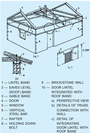
buildings, as listed in Table 17, and detailed in subsequent clauses. Figures 23 and 24 show, schematically, the overall strengthening arrangements to be adopted for category D and E buildings which consist of horizontal bands of reinforcement at critical levels, vertical reinforcing bars at corners, junctions of walls and jambs of openings.
FIG. 23 OVERALL ARRANGEMENT OF REINFORCING LOW STRENGTH MASONRY BUILDINGS
6 — VERTICAL STEEL BAR
8 — HOLDING DOWN BOLT
a) PERSPECTIVE VIEW
b) DETAILS OF TRUSS CONNECTION WITH WALL
c) DETAIL OF INTEGRATING DOOR LINTEL WITH ROOF BAND
FIG. 24 OVERALL ARRANGEMENT OF REINFORCING LOW STRENGTH MASONRY BUILDING HAVING PITCHED ROOF
PART 6 STRUCTURAL DESIGN — SECTION 4 MASONRY
where
8.6.4.2 Lintel band is a band (see 8.1.6) provided at lintel level on all load bearing internal, external longitudinal and cross walls. The specifications of the band are given in 8.6.4.5.
NOTE — Lintel band, if provided in panel or partition walls also shall improve their stability during severe earthquake.
8.6.4.3 Roof band is a band (see 8.1.6) provided immediately below the roof or floors. The specifications
c = roof band and gable band where necessary (see 8.6.4.3 and 8.6.4.4);
d = vertical steel at corners and junctions of walls (see 8.6.4.8);
e = vertical steel at jambs of openings (see 8.6.4.9);
f = bracing in plan at tie level of roofs (see 8.3.4.2.2);
g = plinth band where necessary (see 8.6.4.6); and
h = dowel bars (see 8.6.4.7).
NOTE — In case of four storey buildings of category B, the requirements of vertical steel may be checked through a seismic analysis using a design seismic co-efficient equal to four times the one given in 5 of Part 6 ‘Structural Design, Section 1 Loads, Forces and Effects’ of the Code (this is because the brittle behaviour of masonry in the absence of a vertical steel results in much higher effective seismic force than that envisaged in the seismic coefficient, provided in the Code). If this analysis shows that vertical steel is not required the designer may take the decision accordingly.
NOTE — In coastal areas, the concrete grade shall be M30 concrete and the filling mortar of 1 : 3 (H1) (cement-sand with water proofing admixture).
of the band are given in 8.6.4.5. Such a band need not be provided underneath reinforced concrete or brickwork slabs resting on bearing walls, provided that the slabs are continuous over the intermediate wall up to the crumple sections, if any, and cover the width of end walls, fully or at least 43 of the wall thickness.
8.6.4.4 Gable band is a band provided at the top of gable masonry below the purlins. The specifications of the band are given in 8.6.4.5. This band shall be made continuous with the roof band at the eaves level.
8.6.4.5 Section and reinforcement of band
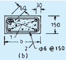
The band shall be made of reinforced concrete of grade not leaner than M20 or reinforced brickwork in cement mortar not leaner than 1 : 3 (H1). The bands shall be of the full width of the wall not less than 75 mm in depth and reinforced with steel, as indicated in Table 18.
Table 18Recommended Longitudinal Steel in Reinforced Concrete Bands
(Sl No.
Span m
Building Category B
Building Category C
Building Category D
Building Category E
No. of Bars (3)
Dia mm (4)
No. of Bars (5)
Dia mm (6)
No. of Bars (7)
Dia mm (8)
No. of Bars (9)
Dia mm (10)
i)
5 or less
2
8
2
8
2
8
2
10
ii)
6
2
8
2
8
2
10
2
12
iii)
7
2
8
2
10
2
12
4
10
iv)
8
2
10
2
12
4
10
4
12
NOTES
1 Span of wall shall be the distance between centre lines of its cross walls or buttresses. For spans greater than 8 m, it shall be desirable to insert pilasters or buttresses to reduce the span or special calculation shall be made to determine the strength of wall and section of band.
2 The number and diameter of bars given above pertain to high strength deformed bars.
3 Width of R.C. band is assumed same as the thickness of the wall. Wall thickness shall be 200 mm minimum. A clear cover of 20 mm from face of wall shall be maintained.
4 The vertical thickness of R.C. band be kept 75 mm minimum, where two longitudinal bars are specified, one on each face; and 150 mm, where four bars are specified.
5 Concrete mix shall be of grade M20 of good practice [6-4(10)].
6 The longitudinal steel bars shall be held in position by steel links or stirrups 6 mm diameter spaced at 150 mm apart.
8.6.4.8 Vertical reinforcement
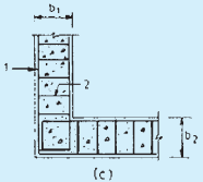
Vertical steel at corners and junctions of walls, which are up to 340 mm (1½ brick) thick, shall be provided as specified in Table 19. For walls thicker than 340 mm the area of the bars shall be proportionately increased. For earthquake resistant framed wall construction, see 8.6.5.
8.6.4.8.1 The vertical reinforcement shall be properly embedded in the plinth masonry of foundations and roof slab or roof band so as to develop its tensile strength in bond. It shall be passing through the lintel bands and floor slabs or floor level bands in all storeys.
Bars in different storeys may be welded {see good practices [6-4(15)] and [6-4(16)], as relevant} or suitably lapped.
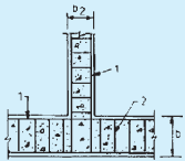
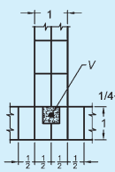
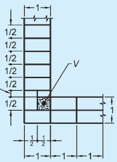
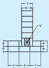
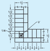
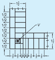
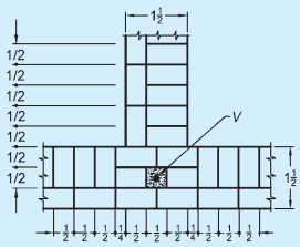
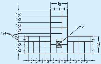
NOTE — Typical details of providing vertical steel in brickwork masonry with rectangular solid units at corners and T-junctions are shown in Fig. 26.
8.6.4.9 Vertical reinforcement at jambs of window and door openings shall be provided as per Table 19. It
Table 19Vertical Steel Reinforcement in Masonry Walls with Rectangular Masonry Units (Clause 8.6.4.8)
Sl No.
No. of Storeys
Storey
Diameter of HSD Single Bar at Each Critical Section mm
Category B(4)
Category C(5)
Category D(6)
Category E(7)
i)
One
—
Nil
Nil
10
12
ii)
Two
a) Top
Nil
Nil
10
12
b) Bottom
Nil
Nil
12
16
iii)
Three
a) Top
Nil
10
10
12
b) Middle
Nil
10
12
16
c) Bottom
Nil
12
12
16
iv)
Four
a) Top
10
10
10
Four
b) Third
10
10
12
storied
c) Second
10
12
16
building
d) Bottom
12
12
20
not permitted
1 The diameters given above are for HSD bars.
2 The vertical bars shall be covered with concrete M20 or mortar 1:3 grade in suitably created pockets around the bars (see Fig. 26). This shall ensure their safety from corrosion and good bond with masonry.
8.6.5Framing of Thin Load Bearing Walls (see Fig. 27)
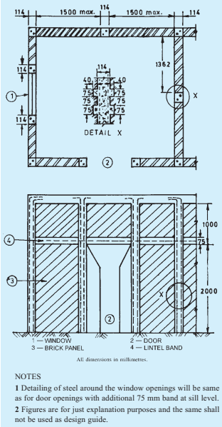
Load bearing walls can be made thinner than 200 mm say 150 mm inclusive of plastering on both sides. Reinforced concrete framing columns and collar beams shall be necessary to be constructed to have full bond with the walls. Columns are to be located at all corners and junctions of walls and spaced not more than 1.5 m apart but so located as to frame up the doors and windows. The horizontal bands or ring beams are located at all floors, roof as well as lintel levels of the openings. The sequence of construction between walls and columns shall be first to build the wall up to 4 to 6 courses height leaving toothed gaps (tooth projection being about 40 mm only) for the
FIG. 27 FRAMING OF THIN LOAD-BEARING BRICK WALL
columns and second to pour M20 (1 : 1½ : 3) concrete to fill the columns against the walls using wood forms only on two sides. The columns steel should be accurately held in position all along. The band concrete should be cast on the wall masonry directly so as to develop full bond with it.
Such construction may be limited to only two storeys maximum in view of its vertical load carrying capacity. The horizontal length of walls between cross walls shall be restricted to 7 m and the storey height to 3 m.
8.6.6Reinforcing Details for Hollow Block Masonry
The following details may be followed in placing the horizontal and vertical steel in hollow block masonry using cement-sand or cement-concrete blocks.
8.6.6.1 Horizontal band
U-shaped blocks may be used for construction of horizontal bands at various levels of the storeys as shown in Fig. 28, where the amount of horizontal reinforcement shall be taken 25 percent more than that given in Table 18 and provided by using four bars and 6 mm diameter stirrups. Other continuity details shall be followed, as shown in Fig. 25.
FIG. 28 U-BLOCKS FOR HORIZONTAL BANDS
8.6.6.2 Vertical reinforcement
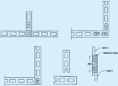
Bars, as specified in Table 19 shall be located inside the cavities of the hollow blocks, one bar in each cavity (see Fig. 29). Where more than one bar is planned these can be located in two or three consecutive cavities. The cavities containing bars are to be filled by using micro-concrete 1:2:3 or cement coarse sand mortar 1:3, and properly rodded for compaction. The vertical bars should be spliced by welding or overlapping for developing full tensile strength. For proper bonding, the overlapped bars should be tied together by winding the binding wire over the lapped length. To reduce the number of overlaps, the blocks may be made U-shaped as shown in Fig. 29 which shall avoid lifting and threading of bars into the hollows.
PART 6 STRUCTURAL DESIGN — SECTION 4 MASONRY
NOTE—OVERLAPPING OF VERTICAL REINFORCEMENT = 50D, AND D = DIAMETER OF THE REINFORCEMENT.
FIG. 29 VERTICAL REINFORCEMENT IN CAVITIES
8.7Floors/Roofs with Small Precast Components
8.7.1 Types of Precast Floors/Roofs
Earthquake resistance measures for floors and roofs with small precast components, as covered in this Section, have been dealt with as typical examples.
8.7.1.1 Precast reinforced concrete unit roof/floor
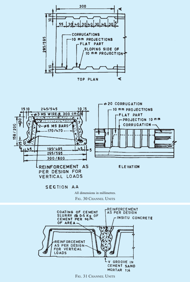
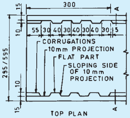
The unit is a precast reinforced concrete component, channel (inverted trough) shaped in section (see Fig. 30). The nominal width of the unit varies from 300 to 600mm, its height from 150 to 200mm and a minimum flange thickness of 30mm. Length of unit shall vary according to room dimensions, but the maximum length is restricted to 4.2m from stiffness considerations. Horizontal corrugations are provided on the two longitudinal faces of the units so that the structural roof/floor acts monolithic after concrete grouted in the joints between the units attains strength (see Fig. 31).
8.7.1.2 Precast reinforced concrete cored unit roof/floor
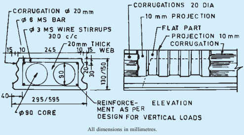
The unit is a reinforced concrete component having a nominal width of 300 to 600 mm and thickness of 130 to 150 mm having two circular hollows 90 mm diameter, throughout the length of the unit (see Fig. 32). The minimum flange/web thickness of the unit shall be 20 mm. Length of unit varies according to room dimensions, but the maximum length shall be restricted to 4.2 m from stiffness considerations. Horizontal corrugations are provided on the two longitudinal faces of the units so that the structural roof/floor acts monolithic after concrete grouted in the joints between the units attains strength (see Fig. 33).
8.7.1.3 Precast reinforced concrete plank and joist scheme for roof/floor
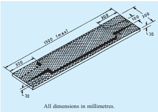
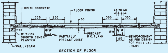
The scheme consists of precast reinforced concrete planks supported on partially precast reinforced concrete joists. The reinforced concrete planks are 300 mm wide and the length varies according to the spacing of the joists, but it shall not exceed 1.5 m (see Fig. 34). To provide monolithic property to the roof/floor and to have T-beam effect with the joists, the planks shall be made partially 30 mm thick and the partially 60 mm thick and in-situ concrete shall be filled in the depressed portions to complete the roof/floor structurally (see Fig. 35).
8.7.1.4 Prefabricated brick panel system for roof/floor
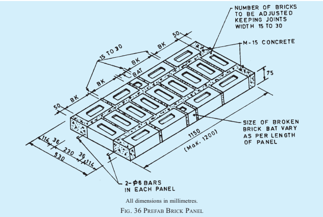
It consists of prefabricated reinforced brick panels (see Fig. 36) supported on Precast reinforced concrete joists with nominal reinforced 35 mm thick structural deck concrete over the brick panels and joists (see Fig. 37). The width of the brick panels shall be 530 mm for panels made of bricks of conventional size and 450 mm for panels made of bricks of modular size. The thickness of the panels shall be 75 mm or 90 mm, respectively depending upon whether conventional or modular bricks are used. The length of the panels shall vary depending upon the spacing of the joists, but the maximum length shall not exceed 1.2 m.
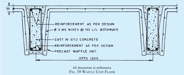
8.7.1.5 Precast reinforced concrete waffle unit roof/floor
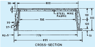
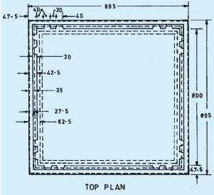
Waffle units are of the shape of inverted troughs, square or rectangular in plan, having lateral dimensions up to 1.2m and depth depending upon the span of the roof/floor to be covered (see Fig. 38 and Fig. 39). The
PART 6 STRUCTURAL DESIGN — SECTION 4 MASONRY
FIG. 32 CORE UNITS
FIG. 34 PRECAST REINFORCED CONCRETE PLANK
All dimensions in millimetres.
FIG. 35 PRECAST REINFORCED CONCRETE PLANK FLOOR
8.7.2 Seismic Resistance Measures
8.7.2.1 All floors and roofs to be constructed with small precast components shall be strengthened as specified for various categories of buildings in Table 20. The strengthening measures are detailed in 8.7.2.3 and 8.7.2.8.
8.7.2.2 Vertical castellation, called shear keys, shall be provided on the longitudinal faces of the channel, cored and waffle units to enable them to transfer horizontal shear force from one unit to the adjacent unit through the in-situ concrete filled in the joints between the units. The minimum percentage of area of shear keys as calculated below, on each face of the unit, shall be 15.
Shear keys shall have a minimum width of 40 mm at its root with the body of the component and shall be to the full height of the component and preferably at uniform spacing. Percentage of area of shear keys shall be calculated as:
Length of the face of the component, in mmNo. of shear keys on one face of the component×40×100
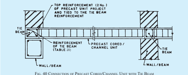
8.7.2.3 Tie beam (see Table 20) is a beam provided all round the floor or roof to bind together all the precast components to make it a diaphragm. The beams shall be to the full width of the supporting wall or beam less the bearing of the precast components. The depth of the beam shall be equal to the depth of the precast components plus the thickness of structural deck concrete, where used over the components. The beam shall be made of cement concrete of grade not leaner
8.8Timber Construction
8.8.1 Timber has higher strength per unit weight and is, therefore, very suitable for earthquake resistant construction. Materials, design and construction in timber shall generally conform to good practice [6-4(17)].
FIG. 40 CONNECTION OF PRECAST Cored/CHANNEL UNIT WITH TIE BEAM
PART 6 STRUCTURAL DESIGN — SECTION 4 MASONRY
All dimensions in millimetres.
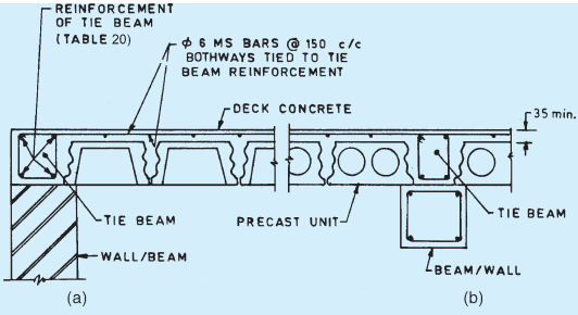
FIG. 41 CONNECTION OF CHANNEL/CORED UNIT FLOOR/ROOF (WITH DECK CONCRETE) WITH TIE BEAM
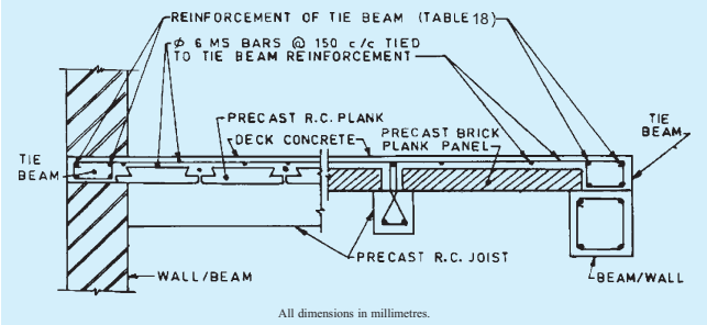
FIG. 42 CONNECTION OF PRECAST REINFORCED CONCRETE PLANK AND PRECAST BRICK PANEL FLOOR/ROOF (WITH DECK CONCRETE) WITH TIE BEAM
8.8.2 Timber (with masonry in-fill) construction shall generally be restricted to two storeys with or without the attic floor.
8.8.3 In timber (with masonry in-fill) construction attention shall be paid to fire safety against electric short circuiting, kitchen fire, etc.
8.8.4 The superstructure of timber buildings shall be made rigid against deformations by adopting suitable construction details at the junctions of the framing members and in wall panels as given in 8.8.6 to 8.8.10
so that the construction as a whole behaves as one unit against earthquake forces.
8.8.5 Foundations
8.8.5.1 Timber construction shall preferably start above the plinth level, the portion below shall be in masonry or concrete.
8.8.5.2 The superstructure may be connected with the foundation in one of the two ways as given below:
a) The superstructure may simply rest on the
All dimensions in millimetres.
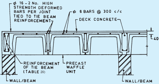
FIG. 43 CONNECTION OF PRECAST WAFFLE UNIT FLOOR/ROOF (WITH DECK CONCRETE) WITH TIE BEAM
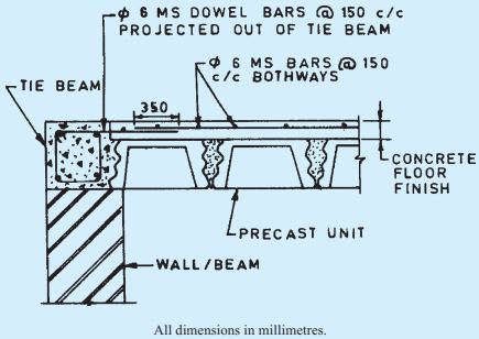
FIG. 44 PROVISION OF REINFORCEMENT IN CONCRETE FLOOR FINISH
plinth masonry, or in the case of small buildings of one storey having plan area less than about 50m2 , it may rest on firm plane ground so that the building is free to slide laterally during ground motion.
1 Past experience has shown that superstructure of the buildings not fixed with the foundation escaped collapse even in a severe earthquake although they were shifted sideways.
2 Where fittings for water supply or water borne sanitation from the house are to be installed, proper attention should be given to permit movement so as to avoid fracture of damage to pipes.
b) The superstructure may be rigidly fixed into
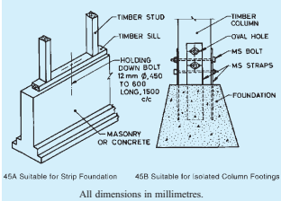
the plinth masonry or concrete foundation as given in Fig. 45 or in case of small building having plan area less than 50m2 , it may be fixed to vertical poles embedded into the ground. In each case the building is likely to move along with its foundation. Therefore, the superstructure shall be designed to carry the resulting earthquake shears.
8.8.6 Types of Framing
The types of construction usually adopted in timber building are as follows:
a) Stud wall construction; and
b) Brick nogged timber frame construction.
PART 6 STRUCTURAL DESIGN — SECTION 4 MASONRY
FIG. 45 DETAILS OF CONNECTION OF COLUMN WITH FOUNDATION
8.8.7 Stud Wall Construction
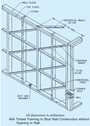
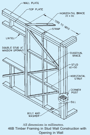
8.8.7.1 The stud wall construction consists of timber studs and corner posts framed into sills, top plates and wall plates. Horizontal struts and diagonal braces are used to stiffen the frame against lateral loads. The wall covering may consist of EKRA, timber or like. Typical details of stud walls are shown in Fig. 46. Minimum sizes and spacing of various members used are specified in 8.8.7.2 to 8.8.7.10.
8.8.7.2 The timber studs for use in load bearing walls
shall have a minimum finished size of 40×90 mm and their spacing shall not exceed those given in Table 21.
8.8.7.3 The timber studs in non-load bearing walls shall not be less than mm in finished cross section. Their spacing shall not exceed 1 m.
8.8.8 Brick Nogged Timber Frame Construction
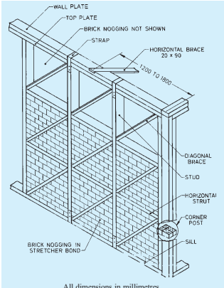
8.8.8.1 The brick nogged timber frame consists of intermediate verticals, columns, sills, wall plates,
horizontal nogging members and diagonal braces framed into each other and the space between framing members filled with tight-fitting brick masonry in stretcher bond. Typical details of brick nogged timber frame construction are shown in Fig. 47. Minimum sizes and spacing of various elements used are specified in 8.8.8.2 to 8.8.8.9.
8.8.8.2 The vertical framing members in brick nogged load bearing walls shall have minimum finished sizes as specified in Table 22.
8.8.8.3 The minimum finished size of the vertical members in non-load bearing walls shall be 40mm×100mm spaced not more than 1.5m apart.
8.8.8.4 The sizes of diagonal bracing members shall be the same as in Table 22.
8.8.8.5 The horizontal framing members in brick-nogged construction shall be spaced not more than 1 m apart. Their minimum finished sizes shall be in accordance with Table 23 and Table 24.
8.8.8.6 The finished sizes of the sill, wall plate and top plate shall be not less than the size of the vertical members used in the wall.
8.8.8.7 Corner posts shall consist of three vertical timbers as described in 8.8.7.7.
8.8.8.8 The diagonal braces shall be connected of their ends with the other members of the wall by means of wire nails as specified in 8.8.7.8.
8.8.9 Notching and Cutting
8.8.9.1 Timber framing frequently requires notching and cutting of the vertical members. The notching or cutting should in general be limited to 20 mm in depth unless steel strips are provided to strengthen the notched face of the members. Such steel strips, where necessary shall be at least 1.5 mm thick and 35 mm wide extending at least 150 mm beyond each side of the notch or cut and attached to the vertical member by means of bolts or screws at each end.
8.8.9.2 The top plate, the wall plate or the sill of a wall may be notched or cut, if reinforcing strip of iron is provided as specified in 8.8.9.1. In case the member is notched or cut not to exceed 40mm in depth, such reinforcing strip may be placed along the notched edge only. Where the notch or cut is more than 40mm in depth or the member is completely cut through, such reinforcing strips shall be placed on both edges of the member. The details of notching and cutting are shown in Fig. 48.
8.8.9.3 Joints in timber shall preferably be bound by metallic fasteners.
8.8.10 Bridging and Blocking
8.8.10.1 All wooden joists shall have at least one row of cross bridging for every 3.5 m length of span. The cross-section of the bridging member shall be a minimum of 40×70 mm and the member shall be screwed or nailed to the joists.
8.8.10.2 All spaces between joists shall be blocked at all bearing with solid blocks not less than 40 mm thick and the full depth of the joists. The block shall be screwed or nailed to the joists as well as to the bearings.
8.9 Confined Masonry Building Construction
For the provisions relating to confined masonry building construction (see Annex E).
8.3.3.4.2 In the case of reinforced concrete slab, the thickness shall not be less than 1/50th of the clear distance between the footings, but not less than 100 mm in any case. It shall be reinforced with not less than 0.15 percent mild steel bars or 0.12 percent high strength deformed bars in each direction placed symmetrically at top and bottom.
8.6.4.5.1 In case of reinforced brickwork, the thickness of joints containing steel bars shall be increased so as to have a minimum mortar cover of 15 mm around the bar. In bands of reinforced brickwork the area of steel provided shall not be less than either as per 10.7.2.2 or specified above for reinforced concrete bands.
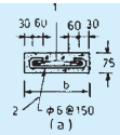
8.6.4.5.2 For full integrity of walls at corners and junctions of walls and effective horizontal bending resistance of bands continuity of reinforcement is essential. The details as shown in Fig. 25 are recommended.
8.6.4.6 Plinth band is a band provided at plinth level of walls on top of the foundation wall. This is to be provided where strip footings of masonry (other than
All dimensions in millimetres.
(d)
a) SECTION OF BAND WITH TWO BARS
b) SECTION OF BAND WITH FOUR BARS
c) STRUCTURAL PLAN AT CORNER JUNCTION
d) SECTION PLAN AT T-JUNCTION OF WALLS
FIG. 25 REINFORCEMENT AND BENDING DETAIL IN R.C. BAND
reinforced concrete or reinforced masonry) are used and the soil is either soft or uneven in its properties, as frequently happens in hill tracts. Where used, its section may be kept same as in 8.6.4.5. This band shall serve as damp proof course as well.
8.6.4.7 In category D and E buildings, to further enhance the box action of walls, steel dowel bars may be used at corners and T-junctions of walls at the sill level of windows to length of 900 mm from the inside corner in each wall. Such dowel may be in the form of U stirrups 8 mm diameter. Where used, such bars shall be laid in 1 : 3 cement-sand-mortar with a minimum clear cover of 20 mm on all sides to minimise corrosion.
3 In case of floors/roofs with small precast components, see also 8.7.2.3 for floor/roof band details.
PART 6 STRUCTURAL DESIGN — SECTION 4 MASONRY
(a)
(b)
(c)
(d)
(e)
(f)
1- One-brick length 21 - Half - brick length , V - Vertical steel bar with mortar/ concrete filling in pocket (a) and (b) - Alternate courses in one brick
(c) and (d) - Alternate courses at corner junction of 121 - brick wall
(e) and (f) - Alternate courses at T- junction of 121 - brick wall
FIG. 26 TYPICAL DETAILS OF PROVIDING VERTICAL Sγ TEEL BARS IN BRICK MASONRY
may start from foundation of floor and terminate in lintel band (see Fig. 22).
PART 6 STRUCTURAL DESIGN — SECTION 4 MASONRY
All dimensions in millimetres. FIG. 38 WAFFLE UNITS
minimum thickness of flange/web shall be 35 mm. Horizontal projections may be provided on all the four external faces of the unit and the unit shall be so shaped that it shall act monolithic with in-situ concrete to ensure load transfer. Vertical castellation, called shear keys, shall be provided on all the four external faces of the precast units to enable them to transfer horizontal shear force from one unit to adjacent unit through in-situ concrete filled in the joints between the units. The waffle units shall be laid in a grid pattern with gaps
between two adjacent units, and reinforcement, as per design, and structural concrete shall be provided in the gaps between the units in both the directions. The scheme is suitable for two way spanning roofs and floors of buildings having large spans.
Table 20Strengthening Measures for Floors/Roofs with Small Precast Components (Clauses 8.7.2.1 and 8.7.2.8)
Sl No.
Building Category
Number of Storeys
Strengthening to be Provided in Floor/Roof with
Channel/Cored Unit
R.C.Planks and Joists
Brick Panels and Joists
Waffle Units
(1)
(2)
(3)
(4)
(5)
(6)
(7)
i)
B
1 to 3
a
a
a
a
4
a, c
a, c
a, d
a
ii)
C
1 and 2
a, b
a
a
a
3 and 4
a, b, c
a, c
a, d
a, e
iii)
D
1 - 4
a, b c
a, c
a, d
a, c, e
iv)
E
1 - 3
a, b, c
a, c
a, d
a, c, e
NOTE
a — Tie beam as per 8.7.2.3;
b — Reinforcing bars of precast unit and tied to tie beam reinforcement as per 8.7.2.4;
c — Reinforced deck concrete as per 8.7.2.5;
d — Reinforced deck concrete as per 8.7.2.6; and
e — Reinforced bars in joint between precast waffle units tied to tie beam reinforcement as per 8.7.2.7.
than M15 and shall be reinforced as indicated in Table 18. If depth of tie is more than 75 mm, equivalent reinforcement shall be provided with one bar of minimum diameter 8 mm at each corner. Tie beams shall be provided on all longitudinal and cross walls. Typical details of the beams are shown in Fig. 40 to Fig. 44.
NOTE — Adequate edge support say 60 mm, shall be provided to precast element on the wall so as to avert its slippage during seismic ground motion.
8.7.2.4 Top reinforcement in the channel or cored units (see Table 20) shall be projected out at both the ends for anchorage length and tied to tie beam reinforcement.
8.7.2.5 Structural deck concrete (see Table 20) of grade
not leaner than M15 shall be provided over precast components or act monolithic. Wherever, deck concrete is to be provided, the top surface of the components shall be finished rough. Cement slurry with 0.5 kg of cement/m² of the surface area shall be applied over the components immediately before laying the deck concrete and the concrete shall be compacted using plate vibrators. The minimum thickness of deck concrete shall be 35 mm or 40 mm reinforced with 6 mm diameter bars and 150 mm apart both ways and anchored into the tie beam placed all round. The maximum size of coarse aggregate used in deck concrete shall not exceed 12 mm.
NOTE — Under conditions of economic constraints, the deck concrete itself could serve as floor finish. The concrete is laid in one operation (see Fig. 44) without joints.
8.7.2.6 The deck concrete normally used over the brick panel with joist floor shall be reinforced with 6 mm diameter bars spaced 150 mm apart both ways (see Table 20)
8.7.2.7 For floors/roofs with precast waffle units, two 16 mm diameter high strength deformed bars shall be provided as top reinforcement in the joints between waffle units, in addition to reinforcement required for taking bending moment for vertical loads. This reinforcement (see Table 20) shall be fixed to tie beam reinforcement.
8.7.2.8 In case of floors/roofs with precast components other than those indicated in Table 20, the buildings shall be analysed for maximum expected seismic forces and the floor/roof shall be designed to act as diaphragm and take care of the resulting forces.
40×70
8.8.7.4 There shall be at least one diagonal brace for every 1.6m×1m area of load bearing walls. Their minimum finished sizes shall be in accordance with Table 22.
8.8.7.5 The horizontal struts shall be spaced not more than 1 m apart. They shall have a minimum size of 30×40 mm for all locations.
8.8.7.6 The finished sizes of the sill, the wall plate and top plate shall not be less than the size of the studs used in the wall.
8.8.7.7 The corner posts shall consist of three timbers, two being equal in size to the studs used in the walls meeting at the corner and the third timber being of a size to fit so as to make a rectangular section (see Fig. 46).
8.8.7.8 The diagonal braces shall be connected at their ends with the stud wall members by means of wire nails having 6 gauge (4.88 mm diameter) and 100 mm length. Their minimum number shall be 4 nails
FIG. 46 STUD WALL CONSTRUCTION
Table 22 Minimum Finished Sizes of Diagonal Braces
Table 21Maximum Spacing of 40 mm × 90 mm Finished Size Studs in Stud Wall Construction (Clause 8.8.7.2)
Sl No.
Group of Timber [Grade I1 ]
Single Storeyed or First Floor of the Double Storeyed Buildings
Ground Floor of Double Storeyed Buildings
Exterior Wall mm (3)
Interior Wall mm (4)
Exterior Wall mm (5)
Interior Wall mm (6)
(1)
(2)
i)
Group A, B
1 000
800
500
400
ii)
Group C
1 000
1 000
500
500
1) Grade I timbers as defined in Table 5 of good practice [6-4(17)].
Sl No.
Building Category (see Table 2)
Group of Timber [Grade I 1) ]
Single Storeyed or First Floor of Double Storeyed Buildings
Ground Floor of Double Storeyed Buildings
Exterior Wall mm × mm (4)
Interior Wall mm × mm (5)
Exterior Wall mm × mm (6)
Interior Wall mm × mm (7)
(1)
(2)
(3)
i)
B, C
All
20 × 40
20 × 40
20 × 40
20 × 40
ii)
D and E
Group A and Group B
20 × 40
20 × 40
20 × 40
30 × 40
Group C
20 × 40
30 × 40
30 × 40
30 × 40
1) Grade I timber as defined in Table 5 of good practice [6-4(17)].
for 20 mm × 40 mm braces and 6 nails for 30 mm × 40 mm braces. The far end of nails may be clutched as far as possible.
8.8.7.9 Horizontal bracing shall be provided at corners of T-junctions of walls at sill, first floor and eaves levels. The bracing members shall have a minimum finished size of 20mm×90mm and shall be connected by means of wire nails to the wall plates at a distance between 1.2m and 1.8m measured from the junction of the walls. There shall be a minimum number of six nails of 6 gauge (4.88 mm diameter) and 100 mm length with clutching as far ends.
8.8.7.10 Unsheathed studding shall not be used adjacent to the wall of another building. The studding shall be sheathed with close jointed 20 mm or thicker boards.
All dimensions in millimetres.
FIG. 47 BRICK NOGGED TIMBER FRAME CONSTRUCTION
PART 6 STRUCTURAL DESIGN — SECTION 4 MASONRY
Table 23Minimum Finished Sizes of Vertical in Brick Nogged Timber Frame Construction (Clauses 8.8.8.5)
Sl No.
Spacing
Group of Timber [Grade I1) ]
Single Storeyed or First Floor of Double Storeyed Buildings
Ground Floor of Double Storeyed Buildings
Exterior Wall mm × mm
Interior Wall mm × mm
Exterior Wall mm × mm
Interior Wall mm × mm
(1)
(2)
(3)
(4)
(5)
(6)
(7)
i)
1
Group A,B
50 × 100
50 × 100
50 × 100
50 × 100
ii)
1.5
Group C
50 × 100
70 × 100
70 × 100
90 × 100
Group A,B
50 × 100
70 × 100
70 × 100
80 × 100
Group C
70 × 100
80 × 100
80 × 100
100 × 100
1) Grade I timber as defined in Table 5 of good practice [6-4(17)].
Table 24Minimum Finished Size of Horizontal Nogging Members (Clause 8.8.8.5)
Sl No.
Spacing of Verticals
Size
m
mm
(1)
(2)
(3)
i)
1.5
70 × 100
ii)
1
50 × 100
iii)
0.5
25 × 100
8.8.8.9 Horizontal bracing members of corners of T-junctions of wall shall be as specified in 8.8.7.9.