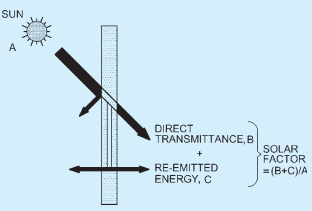
The energy and thermal properties of glass is defined by light transmission, internal and external reflection, solar heat gain coefficient and U-value. The performance requirement for glazing shall be suitably selected. Minimum performance requirement is mentioned in the Annex A.
Specific methods of calculating light and energy factors for glass in buildings are covered here and their characteristic data can serve as a basis for light, heating and ventilation calculations of rooms and can permit comparison between different types of glazing. It is applicable to all flat glass material.
5.2Light Reflectance
5.2.1 External Light Reflectance of Glazing
External light reflectance corresponds to the amount of sunlight reflected by the external glass surface. The
amount of light reflection depends on the type of base glass (substrate tint) and the position of coating on the glass surface.
The external light reflectance of glazing ρv,o shall be calculated using the following formula:
ρv,o=∑λ=380nm780nmDλV
where
ρ0(λ)= spectral external reflectance of glazing, and Dλ,V(λ),Δλ and the integration procedure are defined in 5.1.11.4.
For multiple glazing, the calculation of the spectral external reflectance ρo(λ) shall be performed using the same methods as given in 5.1.11.4 for the calculation of the spectral transmittance τ(λ).
For the spectral external reflectance ρo(λ) as a function of the spectral characteristics of the individual components of the unit, the following formulae are applied:
a) For double glazing;
ρo(λ)=ρ1(λ)+
b) For triple glazing:
ρ
For multiple glazing with more than three components, relationships similar to above equations are found to calculate ρo(λ) of such glazing from the spectral characteristics of the individual components.
As an example for calculating ρo(λ), a glazing composed of five components may be treated in the same way as described in 5.1.11.4.
5.2.2 Internal Light Reflectance of Glazing
Internal light reflectance corresponds to the amount of light reflected by the inner glass surface. The amount of light reflection depends on the type of base glass (substrate tint) and the position of coating on the glass surface.
The internal light reflectance of glazing ρv,i shall be calculated using the following formula:
5.3.2Division of Incident Solar Radiation Flux
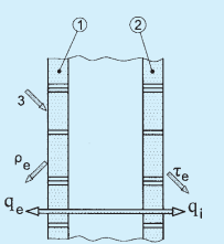
The incident solar radiant flux per unit area φe is divided into the following three parts (see Fig. 7):
a) Transmitted part, τcϱe :
b) Reflected part, ρeφc ; and
c) Absorbed part, αeφe
where
τe= solar direct transmittance,
ρe= solar direct reflectance, and
αe= solar direct absorptances.
The relationship between the three characteristics is:
τe+ρe+αe=
SUN
FIG. 6 SOLAR HEAT GAIN COEFFICIENT
KEY
1 OUTER PANE
2 SECOND INNER PANE
3UNIT INCIDENT RADIANT FLUX
ρe=0.38;qe=0.17;
τe=0.41;qi=0.04;thereforeg=0.45
FIG. 7 COMPONENTS OF INCIDENT SOLAR RADIANT FLUX
PART 6 STRUCTURAL DESIGN — SECTION 8 GLASS AND GLAZING
The absorbed part αeφe is subsequently divided into two parts qiφ and , which are energy transferred to the inside and outside, respectively:
αe=qi+qe
where
qi= secondary heat transfer factor of the glazing towards the inside; and
qe = secondary heat transfer factor of the glazing towards the outside.
5.3.4Solar Direct Reflectance
The solar direct reflectance ρe of the glazing shall be calculated using the following formula:
ρe=∑λ=300nm2500nmSλΔλ
where
Sλ = relative spectral distribution of the solar radiation (see 5.3.3);
ρo(λ)= spectral external reflectance of the glazing; and
Δλ = integration procedure are the same as in light transmittance except that the data points shall be chosen at the wavelengths given in Table 11.
In the case of multiple glazing, the spectral external reflectance ρo(λ) is calculated in accordance with 5.2.1.
Table 11Normalized Relative Spectral Distribution of Global Solar Radiation (Clauses 5.3.3, 5.3.4, 5.3.6.3 and 5.3.6.4)
lnm(1)
SλΔλ(2)
300
0
305
0.000 057
310
0.000 236
315
0.000 554
320
0.000 916
325
0.001 309
330
0.001 914
335
0.002 018
340
0.002 189
345
0.000 260
350
0.002 445
355
0.002 555
360
0.002 683
365
0.003 020
370
0.003 359
375
0.003 509
380
0.003 600
385
0.003 529
390
0.003 551
395
0.004 294
400
0.007 812
410
0.011 638
420
0.011 877
430
0.011 347
440
0.013 245
450
0.015 343
460
0.016 166
470
0.016 178
5.3.5Solar Direct Absorptance
The solar direct absorptance αe shall be calculated from the following formula:
τe+ρe+αe=1
5.3.6 Secondary Heat Transfer Factor Towards the Inside
5.3.6.1 Boundary conditions
For the calculation of the secondary heat transfer factor towards the inside, qi , the heat transfer coefficients of the glazing towards the outside, he , and towards the inside, hi , are needed. These values mainly depend on the position of the glazing, wind velocity, inside and outside temperatures and, furthermore, on the temperature of the two external glazing surfaces.
5.3.6.2 Single glazing
The secondary heat transfer factor towards the inside, qi, of single glazing shall be calculated using the following formula:
qi=α
5.3.6.3 Double glazing
The secondary heat transfer factor towards the inside, qi, of double glazing shall be calculated using the following formula:
q
5.3.6.4 Multiple glazing with n>2 components
The secondary heat transfer factor towards the inside, qi, of a multiple glazing with more than two components shall be calculated using the following formula:
5.3.6.5 Mean radiant temperature (MRT)
MRT can be calculated by various methods, among which measuring with globe thermometer is the most common and is given by:
MRT=4Tg
5.4Total Solar Energy Transmission
The total solar energy transmitted into the room per unit area of glazing φei is given by the relationship:
φei=φeg
where
φe= incident solar radiation flux per unit area;
g = total solar energy transmittance of the glazing; and
The values of φe can be obtained from appropriate tables in meteorological literature.
NOTE — The SHGC/SF requirement for the glazing should be selected based on the prescriptive requirements are mentioned in Annex A.
5.4.1 Additional Heat Transfer
If the room temperature Ti differs from the outside temperature To, an additional heat transfer occurs in addition to φ. This additional heat flow can be calculated as follows:
5.6$U$-Value
Heat transmittance through a surface by conduction, convection, and radiation is expressed by its U-value. U-value is the amount of heat transferred that is lost or gained due to a temperature differential of 1 K through 1 m². The rate of heat transfer (U-value) is minimised by the use of double glazing, using gas inside cavity or by using low-E glass for inside pane of double glazed unit.
The U-value requirement for the glazing system should be selected in accordance with the Table 13 and Annex A.
Table 12Normalized Relative Spectral Distribution of Global Solar Radiation (Clause 5.5)
Sl No.
λnm(2)
SλΔλ(3)
i)
300
0
ii)
305
0.001 859
iii)
310
0.007 665
iv)
315
0.017 961
v)
320
0.029 732
vi)
325
0.042 466
vii)
330
0.062 108
viii)
335
0.065 462
ix)
340
0.071 020
x)
345
0.073 326
xi)
350
0.079 330
xii)
355
0.082 894
xiii)
360
0.087 039
xiv)
365
0.097 963
xv)
370
0.108 987
xvi)
375
0.113 837
xvii)
380
0.058 351
NOTE — The values in this table are calculated according to the trapezoidal rule.
Table 13Thermal Performance of Different Glass Shading Devices (Clause 5.6)
Sl No.(1)
Name of the Shading Device(2)
Transmittance,U-Value(3)
Shade Factor(4)
i)
Plain glass sheet (3.0 mm thick)
5.23
1.00
ii)
Plain glass + Wire mesh outside
5.00
0.65
iii)
Painted glass:a) White paintb) Yellow paintc) Green paint
ρi(λ)=spectral internal reflectance of glazing, and Dλ,V(λ),Δλ and the integration procedure are as defined in light transmittance.
For multiple glazing, the calculation of the spectral internal reflectance ρi(λ) shall be performed using the same methods as given in 5.1.11.4 for the calculation of the spectral transmittance τ(λ).
For the spectral internal reflectance ρi(λ) as a function of the spectral characteristics of the individual components of the unit, the following formulae are applied.
For multiple glazing with more than three components, relationships similar to above expressions are found to calculate ρi(λ) of such glazing from the spectral characteristics of the individual components.
1
e
qeφe
∑λ=300nm2500nmρo(λ)SλΔλ
480
0.016 402
490
0.015 794
500
0.015 801
510
0.015 973
520
0.015 357
530
0.015 857
540
0.015 827
550
0.015 844
560
0.015 590
570
0.015 255
580
0.014 745
590
0.014 330
600
0.014 663
610
0.015 030
620
0.014 859
630
0.014 622
640
0.014 526
650
0.014 445
660
0.014 313
670
0.014 023
680
0.012 838
690
0.011 788
700
0.012 453
710
0.012 798
720
0.010 589
730
0.011 233
740
0.012 175
750
0.012 181
760
0.009 515
770
0.010 479
780
0.011 381
790
0.011 262
800
0.026 718
Table 11 — (Concluded)
Table 11 — (Concluded)
(1)
(2)
850
0.048 240
900
0.040 297
950
0.021 384
1 000
0.036 097
1 050
0.034 110
1 100
0.018 861
1 150
0.013 228
1 200
0.022 551
1 250
0.023 376
1 300
0.017 756
1 350
0.003 743
1 400
0.000 741
1 450
0.003 792
1 500
0.009 693
1 550
0.013 693
1 600
0.012 203
1 650
0.010 615
1 700
0.007 255
1 750
0.007 183
1 800
0.002 157
1 850
0.000 395
1 900
0.000 082
1 950
0.001 087
2 000
0.003 024
2 050
0.003 988
2 100
0.004 229
2 150
0.004 142
2 200
0.003 690
2 250
0.003 592
2 300
0.003 436
2 350
0.003 163
2 400
0.002 233
2 450
0.001 202
2 500
0.000 475
NOTE — The values in this table are calculated according to the trapezoidal rule.
NOTE — The values in this table are calculated according to the trapezoidal rule.
As the purpose of this Section is to provide basic information on the performance of glazing, the following conventional conditions have been stated for simplicity:
a) Position of the glazing: vertical;
b) Outside surface: wind velocity approximately 4 m/s; corrected emissivity 0.837;
c) Inside surface: natural convection; emissivity optional; and
d) Air spaces are unventilated.
Under these conventional, average conditions, standard values for he and hi are obtained:
he=23W/m2K
hi=(3.6+0.8374.4εi)W/m2K
where
εi = corrected emissivity of the inside surface [for soda lime glass, εi = 0.837 and hi = 8 W/m²K].
If other boundary conditions are used to meet special requirements they shall be stated in the test report.
Values for εi lower than 0.837 (due to surface coatings with higher reflectance in the far infrared) should only to be taken into account if condensation on the coated surface can be excluded.
e
he+hihi
where
αe= solar direct absorptance obtained from the in accordance with 5.3.2, and
he,hi= heat transfer coefficients towards the outside and inside, respectively, in accordance with 7.6.1.
i
=
(hi1+he1+Λ1)(heαe1+αe2+)
where
αe1= solar direct absorptance of the outer (first) pane within the double glazing;
αe2= solar direct absorptance of the second pane within the double glazing;
Λ = thermal conductance between the outer surface and the innermost surface of the double glazing (see Fig. 8), in Watt Per square metre per Kelvin (W/m 2 K); and
PART 6 STRUCTURAL DESIGN — SECTION 8 GLASS AND GLAZING
KEY
1 PANE 1
2 PANE 2
3 OUTSIDE
4 INSIDE
FIG. 8 ILLUSTRATION OF THE MEANING OF THERMAL CONDUCTANCE, Λ
he,hi= heat transfer coefficients towards the outside and the inside, respectively in accordance with 5.3.6.1.
Characteristics αe1 and αe2 are calculated as follows:
αe1=∑λ=300nm2500nmSλΔλ∑λ=300nm
αc2=∑λ=300nm2500nmSλΔλ∑λ=300nm
where
τ1(λ),τ2(λ),ρ1(λ),ρ1′(λ) and ρ2(λ) are as defined in light transmittance.
α1(λ)= spectral direct absorptance of the outer pane, measured in the direction of the incident radiation, given by the relationship:
α1(λ)=1−τ1(λ)−ρ1(λ)
α1′(λ)= spectral direct absorptance of the outer pane, measured in the opposite direction to the incident radiation, given by the relationship: α1′(λ)=1−τ1(λ)−ρ1′(λ)
α2(λ)= spectral direct absorptance of the second
pane, measured in the direction of the incident radiation, given by the relationship:
α2(λ)=1−τ2(λ)−ρ2(λ)
Δλ and the integration procedure are the same as in 5.1.11.4 except that the data points shall be chosen at the wavelengths given in Table 11.
The thermal conductance Λ shall be determined for a temperature difference of ΔT=15∘C across the sample and a mean temperature of the sample of 10∘C , or by measuring methods using the standard guarded hot plate method, or the standard heat flow metre method.
If another temperature difference ΔT across the sample and/or another mean temperature of the sample is used for the determination of the thermal conductance Λ to meet special requirements, this shall be stated in the test report.
αe1 = solar direct absorptance of the outer (first)
pane within the n-fold glazing;
αe2 = solar direct absorptance of the second pane within the n-fold glazing;
αen= solar direct absorptance of the nth (inner) pane of the n-fold glazing;
he,hi= heat transfer coefficients towards the outside and towards the inside, respectively in accordance with 5.3.6.1;
Λ12 = thermal conductance between the outer surface of the outer (first) pane and the centre of the second pane (see Fig. 9);
Λ(n−1)n= thermal conductance between the centre of the (n−1)th pane and the outer surface of the nth (inner) pane (see Fig. 9); and
Λ23 = thermal conductance between the centre of the second pane and the centre of the third pane (see Fig. 9);
The thermal conductances Λ12, Λ23......Λ(n−1)n shall be determined by iteration technique. The calculation of the direct solar absorptances αe1,αe2,…,αen shall be performed using the methods given in 5.3.6.3.
FIG. 9 ILLUSTRATION OF THE MEANING OF THE THERMAL CONDUCTANCES Λ12,Λ23…Λ(n−1)n
As an example for the calculation of the direct solar absorptances the following procedure is given which consist of the following (n−1) steps for a glazing consisting of n components:
a) First step — Calculate the spectral characteristics of a unit consisting of (n−1)
components 2, 3,......n according to what has been prescribed in 5.1.11.4 and 6.1. Then combine this unit with the first (outer) pane as a double glazing.
b) Second step — Calculate the spectral characteristics of a unit consisting of the (n−2) components 3, ..., n and furthermore, those of a double glazing consisting of pane 1 and pane 2. These units are then combined as a double glazing. The sum αe1+αe2 is then obtained. This procedure is continued up to the last (n−1)th step.
c) (n−1)th step — Combine the (n−1) panes 1,2,…(n−1) and determine the spectral characteristics of this unit. This unit is then combined with the nth (inner) pane as a double glazing. From the second equation in 5.3.6.3, the sum αe1,αe2 ... αe(n−1) is obtained, that is with the known values αe1,αe2,…αe(n−2) from the previous steps αe(n−1) is determined. αen is obtained according to the expression of αe2 in 5.3.6.3.
In the case of triple glazing for the solar absorptances αe1, αe2 and αe3 as a function of the spectral characteristics of the individual components of the unit, the following formulae are obtained: