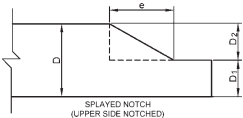
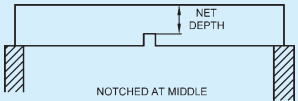
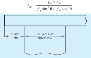
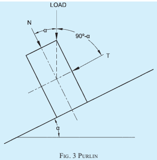
NOTE — The formulae given are for columns with pin end conditions and the length shall be modified suitably with other end conditions.
6.6.1 Solid Columns
Solid columns shall be classified into short, intermediate and long columns depending upon their slenderness ratio (S/d) as follows:
a) Short columns — Where S/d does not exceed 11,
b) Intermediate columns — Where S/d is between 11 and Kg, and
c) Long columns — Where S/d is greater than K8.
6.6.1.1 For short columns, the permissible compressive stress shall be calculated as follows:
PART 6 STRUCTURAL DESIGN — SECTION 3 TIMBER AND BAMBOO: 3A TIMBER
6.6.1.2 For intermediate columns, the permissible compressive stress is calculated by using the following formula:
6.6.1.3 For long columns, the permissible compressive stress shall be calculated by using the following formula:
6.6.1.4 In case of solid columns of timber, S/d ratio shall not exceed 50.
6.6.1.5 The permissible load on a column of circular cross section shall not exceed that permitted for a square column of an equivalent cross sectional area, where side of square is equal to 0.886 times the diameter
6.6.1.6 For determining S/d ratio of a tapered column, such as for wooden poles, its least dimension shall be taken as the sum of the corresponding least dimensions at the small end of the column and one-third of the difference between this least dimension at the small end and the corresponding least dimension at the large end, but in no case shall the least dimension for the column be taken as more than one and a half times the least dimension at the small end. The induced stress at the small end of the tapered column shall not exceed the permissible compressive stress in the direction of grain.
6.6.2 Built-Up Columns
6.6.2.1 Box column
Box columns shall be classified into short, intermediate and long columns as follows:
a) Short columns — Where d12+d22 is less than 8;
6.6.3 Spaced Columns
6.6.3.1 The formulae for solid columns as specified in 6.6.1 are applicable to spaced columns with a restraint factor of 2.5 or 3, depending upon distances of end connectors in the column.
NOTE — A restrained factor of 2.5 for location of centroid group of fasteners at S/20 from end and 3 for location at S/10 to S/20 from end shall be taken.
6.6.3.2 For intermediate spaced column, the permissible compressive stress shall be:
6.7 Tension Member (Ties)
The stress is axial tension parallel to grain of wood shall be calculated on the basis of net-section area which shall not exceed the safe permissible value in tension parallel to grain
6.8 Structural Members Subject to Bending and Axial Stresses
6.8.1 Structural members subjected both to bending and axial compression shall be designed to comply with the following:
6.9 Timber Roof Truss
Trusses are framed structures in which separate straight members are so arranged and connected at their ends that members form triangles. The external loads cause direct stresses in the members. Essentially a plane structure which is very stiff in the plane of the members but very flexible in every other direction. For members subjected to reversal of stresses, design has to be for one stress and tested for the other applied at the panel points. Eccentricity of meeting members at joint may result in the increased stresses in design.