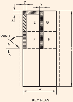
The average external pressure coefficients and pressure concentration coefficients for pitched roofs of rectangular clad building shall be as given in Table 9. Where no pressure concentration coefficients are given, the average coefficients shall apply. The pressure coefficients on the underside of any overhanging roof shall be taken in accordance with 4.5.3.3.5.
1 The pressure concentration shall be assumed to act outward (suction pressure) at the ridges, eaves, cornices and corners of roofs.
2 The pressure concentration shall not be included with the net external pressure when computing overall loads.
3 For hipped roofs, pressure coefficients (including local values) may be taken on all the four slopes, as appropriate from Table 9, and be reduced by 20 percent for the hip slope.
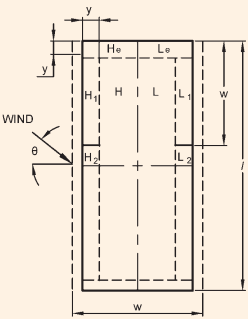
For mono slope roofs of rectangular clad buildings, the average pressure coefficient and pressure concentration coefficient for monoslope (lean-to) roofs of rectangular clad buildings shall be as given in Table 10.
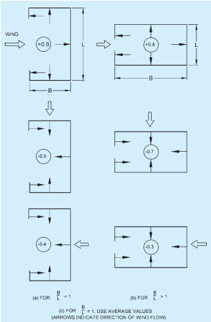
FIG. 2 VALUES OF INTERNAL PRESSURE COEFFICIENTS WITH RESPECT TO THE DIRECTION OF WIND FOR BUILDINGS WITH ONE SIDE OPENINGS
| Building Height Ratio | Building Plan Ratio | Elevation | Plan | Wind Angle Θ Degree | for Surface | Local | |||
| A | B | C | D | ||||||
| 090 | +0.7-0.5 | -0.2-0.5 | -0.5+0.7 | -0.5-0.2 | }-0.8 | ||||
| 090 | +0.7-0.5 | -0.25-0.5 | -0.6+0.7 | -0.6-0.1 | }-1.0 | ||||
| 090 | +0.7-0.6 | -0.25-0.6 | -0.6+0.7 | -0.6-0.25 | }-1.1 | ||||
| 090 | +0.7-0.5 | -0.3-0.5 | -0.7+0.7 | -0.7-0.1 | }-1.1 | ||||
| 090 | +0.8-0.8 | -0.25-0.8 | -0.8+0.8 | -0.8-0.25 | }-1.2 | ||||
| 090 | +0.7-0.5 | -0.4-0.5 | -0.7+0.8 | -0.7-0.1 | }-1.2 | ||||
| 090 | +0.95-0.8 | -1.85-0.8 | -0.9+0.9 | -0.9-0.85 | }-1.25 | ||||
| 090 | +0.95-0.7 | -1.25-0.7 | -0.7+0.95 | -0.7-1.25 | }-1.25 | ||||
| 090 | +0.85-0.75 | -0.75-0.75 | -0.75+0.85 | -0.75-0.75 | }-1.25 | ||||
NOTE — is the height to eaves or parapet, is the greater horizontal dimension of a building and is the lesser horizontal dimension of a building.
PART 6 STRUCTURAL DESIGN — SECTION 1 LOADS, FORCES AND EFFECTS
| Building Height Ratio | Roof Angle α Degree | Wind Angle θ 0° | Wind Angle θ 90° | Local Coefficients | |||||
| EF | GH | EG | FH | ||||||
| 0 | -0.8 | -0.4 | -0.8 | -0.4 | -2.0 | -2.0 | -2.0 | ||
| 5 | -0.9 | -0.4 | -0.8 | -0.4 | -1.4 | -1.2 | -1.2 | ||
| 10 | -1.2 | -0.4 | -0.8 | -0.6 | -1.4 | -1.4 | |||
| 20 | -0.4 | -0.4 | -0.7 | -0.6 | -1.0 | ||||
| 30 | 0 | -0.4 | -0.7 | -0.6 | -0.8 | ||||
| 45 | +0.3 | -0.5 | -0.7 | -0.6 | |||||
| 60 | +0.7 | -0.6 | -0.7 | -0.6 | |||||
| 0 | -0.8 | -0.6 | -1.0 | -0.6 | -2.0 | -2.0 | -2.0 | ||
| 5 | -0.9 | -0.6 | -0.9 | -0.6 | -2.0 | -2.0 | -1.5 | ||
| 10 | -1.1 | -0.6 | -0.8 | -0.6 | -2.0 | -2.0 | -1.5 | ||
| 20 | -0.7 | -0.5 | -0.8 | -0.6 | -1.5 | -1.5 | -1.5 | ||
| 30 | -0.2 | -0.5 | -0.8 | -0.8 | -1.0 | ||||
| 45 | +0.2 | -0.5 | -0.8 | -0.8 | |||||
| 60 | +0.6 | -0.5 | -0.8 | -0.8 | |||||
| 0 | -0.7 | -0.6 | -0.9 | -0.7 | -2.0 | -2.0 | -2.0 | ||
| 5 | -0.7 | -0.6 | -0.8 | -0.8 | -2.0 | -2.0 | -1.5 | ||
| 10 | -0.7 | -0.6 | -0.8 | -0.8 | -2.0 | -2.0 | -1.5 | ||
| 20 | -0.8 | -0.6 | -0.8 | -0.8 | -1.5 | -1.5 | -1.5 | ||
| 30 | -1.0 | -0.5 | -0.8 | -0.7 | -1.5 | ||||
| 40 | -0.2 | -0.5 | -0.8 | -0.7 | -1.0 | ||||
| 50 | +0.2 | -0.5 | -0.8 | -0.7 | |||||
| 60 | +0.5 | -0.5 | -0.8 | -0.7 | |||||
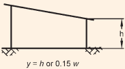
or 0.15 w
Whichever is the lesser.
NOTES
1 is the height to eaves or parapet and is the lesser horizontal dimension of a building.
2 Where no local coefficients are given, the overall coefficient apply.
3 For hipped roofs the local coefficient for the hip ridge may be conservatively taken as the appropriate ridge value.
4 and are dimensions between the walls excluding overhangs.
Table 10 External Pressure Coefficients ( ) for Monoslope Roofs for Rectangular Clad Buildings (Clause 4.5.3.3.2)
Whichever is the lesser.
NOTE :- Area H and area L refer to the whole quadrant.
| Roof Angle α Degree | Wind Angle θ | Local Coefficients (Cpe) | ||||||||||||||
| 0° | 45° | 90° | 135° | 180° | ||||||||||||
| H | L | H | L | H/L * | H/L ** | H | L | H | L | H1 | H2 | L1 | L2 | He | Le | |
| 5 | -1.0 | -0.5 | -1.0 | -0.9 | -1.0 | -0.5 | -0.9 | -1.0 | -0.5 | -1.0 | -2.0 | -1.5 | -2.0 | -1.5 | -2.0 | -2.0 |
| 10 | -1.0 | -0.5 | -1.0 | -0.8 | -1.0 | -0.5 | -0.8 | -1.0 | -0.4 | -1.0 | -2.0 | -1.5 | -2.0 | -1.5 | -2.0 | -2.0 |
| 15 | -0.9 | -0.5 | -1.0 | -0.7 | -1.0 | -0.5 | -0.6 | -1.0 | -0.3 | -1.0 | -1.8 | -0.9 | -1.8 | -1.4 | -2.0 | -2.0 |
| 20 | -0.8 | -0.5 | -1.0 | -0.6 | -0.9 | -0.5 | -0.5 | -1.0 | -0.2 | -1.0 | -1.8 | -0.8 | -1.8 | -1.4 | -2.0 | -2.0 |
| 25 | -0.7 | -0.5 | -1.0 | -0.6 | -0.8 | -0.5 | -0.3 | -0.9 | -0.1 | -0.9 | -1.8 | -0.7 | -0.9 | -0.9 | -2.0 | -2.0 |
| 30 | -0.5 | -0.5 | -1.0 | -0.6 | -0.8 | -0.5 | -0.1 | -0.6 | 0 | -0.6 | -1.8 | -0.5 | -0.5 | -0.5 | -2.0 | -2.0 |
* Applied to length w / 2 from wind-ward end.
** Applies to remainder
NOTES
1 is the height of eaves at lower side, is the greater horizontal dimensions of a building and is the
lesser horizontal dimension of a building.
2 and are overall length and width including overhangs.
PART 6 STRUCTURAL DESIGN — SECTION 1 LOADS, FORCES AND EFFECTS
4.5.3.3.3 Canopy roofs with and
The pressure coefficients are given in Tables 11 and 12 separately for monopitch and double pitch canopy roofs such as open-air parking garages, shelter areas, outdoor areas, railway platforms, stadiums and theatres. The coefficients take into account of the combined effect of the wind exerted on and under the roof for all wind directions; the resultant is to be taken normal to the canopy. Where the local coefficients overlap, the greater of the two given values should be taken. However, the effect of partial closures of one side and or both sides, such as those due to trains, buses and stored materials shall be foreseen and taken into account.
The solidity ratio, , is equal to the area of obstructions under the canopy divided by the gross area under the canopy, both areas normal to the wind direction. represents a canopy with no obstructions underneath. represents the canopy fully blocked with contents to the downwind eaves. Values of for intermediate solidities may be linearly interpolated between these two extremes, and apply upwind of the position of maximum blockage only. For downwind of the position of maximum blockage, the coefficients for may be used.
In addition to the forces due to the pressures normal to the canopy, there will be horizontal loads on the canopy due to the wind pressure on any fascia and to friction over the surface of the canopy. For any wind direction, only the greater of these two forces need to be taken into account. Fascia loads should be calculated on the area of the surface facing the wind, using a force coefficient of 1.3. Frictional drag should be calculated using the coefficients given in 4.5.4.1.
NOTE — Tables 13 to 18 may be used to get internal and external pressure coefficients for pitches and troughed free roofs for some specific cases for which aspect ratios and roof slopes have been specified. However, while using Tables 13 to 18 any significant departure from it should be investigated carefully. No increase shall be made for local effects except as indicated.
4.5.3.3.4 Pitched and saw-tooth roofs of multi-span buildings
For pitched and saw-tooth roofs of multi-span buildings, the external average pressure coefficients shall be as given in Tables 19 and 20, respectively provided that all the spans shall be equal and the height to the eaves shall not exceed the span.