39.1 Nominal Shear Stress
The nominal shear stress, , in beams of uniform depth shall be obtained by the following equation:
where
shear force due to design loads;
b = breadth of the member, which for flanged section shall be taken as the breadth of the web, ; and
effective depth.
39.1.1 Beams of Varying Depth
In the case of beams of varying depth the equation shall be modified as:
where
and d are the same as in 39.1,
bending moment at the section, and
β = angle between the top and the bottom edges of the beam.
The negative sign in the formula applies when the bending moment increases numerically in the same direction as the effective depth d increases, and the positive sign when the moment decreases numerically in this direction.
39.2 Design Shear Strength of Concrete
39.2.1 The design shear strength of concrete in beams without shear reinforcement is given in Table 19.
PART 6 STRUCTURAL DESIGN — SECTION 5 CONCRETE: 5A PLAIN AND REINFORCED CONCRETE
Table 19 Design Shear Strength of Concrete, , N/mm²
(Clauses 39.2.1, 39.2.2, 39.3, 39.4, 39.5.3, 40.3.2, 40.3.3 and 40.4.3)
| Sl No. | Concrete Grade | ||||||
| M 15(3) | M 20(4) | M 25(5) | M 30(6) | M 35(7) | M 40 and Above(8) | ||
| i) | ≤ 0.15 | 0.28 | 0.28 | 0.29 | 0.29 | 0.29 | 0.30 |
| ii) | 0.25 | 0.35 | 0.36 | 0.36 | 0.37 | 0.37 | 0.38 |
| iii) | 0.50 | 0.46 | 0.48 | 0.49 | 0.50 | 0.50 | 0.51 |
| iv) | 0.75 | 0.54 | 0.56 | 0.57 | 0.59 | 0.59 | 0.60 |
| v) | 1.00 | 0.60 | 0.62 | 0.64 | 0.66 | 0.67 | 0.68 |
| vi) | 1.25 | 0.64 | 0.67 | 0.70 | 0.71 | 0.73 | 0.74 |
| vii) | 1.50 | 0.68 | 0.72 | 0.74 | 0.76 | 0.78 | 0.79 |
| viii) | 1.75 | 0.71 | 0.75 | 0.78 | 0.80 | 0.82 | 0.84 |
| ix) | 2.00 | 0.71 | 0.79 | 0.82 | 0.84 | 0.86 | 0.88 |
| x) | 2.25 | 0.71 | 0.81 | 0.85 | 0.88 | 0.90 | 0.92 |
| xi) | 2.50 | 0.71 | 0.82 | 0.88 | 0.91 | 0.93 | 0.95 |
| xii) | 2.75 | 0.71 | 0.82 | 0.90 | 0.94 | 0.96 | 0.98 |
| xiii) | 3.00 and above | 0.71 | 0.82 | 0.92 | 0.96 | 0.99 | 1.01 |
NOTE — The term is the area of longitudinal tension reinforcement which continues at least one effective depth beyond the section being considered except at support where the full area of tension reinforcement may be used provided the detailing conforms to 25.2.2 and 25.2.3.
39.2.1.1 For solid slabs, the design shear strength for concrete shall be , where has the values given below:
| OverallDepth ofSlabmm | 300ormore | 275 | 250 | 225 | 200 | 175 | 150orless | |
|---|---|---|---|---|---|---|---|---|
| k | 1.00 | 1.05 | 1.10 | 1.15 | 1.20 | 1.25 | 1.30 |
NOTE — This provision shall not apply to flat slabs for which 30.6 shall apply.
39.2.2 Shear Strength of Members Under Axial Compression
For members subjected to axial compression , the design shear strength of concrete, given in Table 19, shall be multiplied by the following factor:
but not exceeding 1.5
where
axial compressive force, in N;
gross area of the concrete section, in ; and
= characteristic compressive strength of concrete.
| Concrete Grade | M 15 | M 20 | M 25 | M 30 | M 35 | M 40 and Above |
|---|---|---|---|---|---|---|
| 2.5 | 2.8 | 3.1 | 3.5 | 3.7 | 4.0 |
39.2.3 With Shear Reinforcement
Under no circumstances, even with shear reinforcement, shall be nominal shear stress in beams exceed given in Table 20.
39.2.3.1 For solid slabs, the nominal shear stress shall not exceed half the appropriate values given in Table 20.
Maximum shear stress, given in Table 20 is valid for all load cases including earthquake except the following:
a) For coupled beams only, under earthquake forces, the limiting value of given in Table 20 shall be superseded by F-9.
b) Coupled shear walls shall be connected by ductile coupling beams. If the earthquake induced shear stress in the coupling beam exceeds,
where is the clear span of the coupling beam and D is its overall depth, the entire earthquake induced shear and flexure shall, preferably, be resisted by diagonal reinforcement.
The area of reinforcement to be provided along each diagonal in a diagonally reinforced coupling beam shall be,
where is the factored shear force and is the angle made by the diagonal reinforcement with the horizontal. At least 4 bars of 8 mm diameter shall be provided along each diagonal. The reinforcement along each diagonal shall be enclosed by special confining reinforcement, as per F-7. The pitch of spiral or spacing of ties shall not exceed 100 mm.
The diagonal or horizontal bars of a coupling beam shall be anchored in the adjacent walls with an anchorage length of 1.5 times the development length in tension.
39.3 Minimum Shear Reinforcement
70
When is less than given in Table 19, minimum shear reinforcement shall be provided in accordance with 25.5.1.6.
39.4 Design of Shear Reinforcement
When exceeds given in Table 19, shear reinforcement shall be provided in any of the following forms:
a) Vertical stirrups,
b) Bent-up bars along with stirrups, and
c) Inclined stirrups
Where bent-up bars are provided, their contribution towards shear resistance shall not be more than half that of the total shear reinforcement.
Shear reinforcement shall be provided to carry a shear equal to . The strength of shear reinforcement shall be calculated as below:
- For vertical stirrups:
- For inclined stirrups or a series of bars bent-up at different cross-sections:
- For single bar or single group of parallel bars, all bent-up at the same cross-section:
where
total cross-sectional area of stirrup legs or bent-up bars within a distance ,
spacing of the stirrups or bent-up bars along with the length of the member,
nominal shear stress,
design shear strength of the concrete,
breadth of the member which for flanged beams, shall be taken as the breadth of the web
= characteristic strength of the stirrup or bent-up reinforcement which shall not be taken greater than 415 N/mm ,
angle between the inclined stirrup or bent-up bar and the axis of the member, not less than ,and
effective depth.
NOTES
1 Where more than one type of shear reinforcement is used to reinforce the same portion of the beam, the total shear resistance shall be computed as the sum of the resistance for the various types separately.
2 The area of the stirrups shall not be less than the minimum specified in 25.5.1.6.
39.5 Enhanced Shear Strength of Sections Close to Supports
39.5.1 General
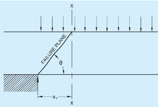
NOTE — The shear causing failure is that acting on section X-X.
FIG. 24 SHEAR FAILURE NEAR SUPPORTS
Shear failure at sections of beams and cantilevers without shear reinforcement will normally occur on plane inclined at an angle to the horizontal. If the angle of failure plane is forced to be inclined more steeply than this [because the section considered in Fig. 24 is close to a support or for other reasons], the shear force required to produce failure is increased.
The enhancement of shear strength may be taken into account in the design of sections near a support by increasing design shear strength of concrete to provided that design shear stress at the face of the support remains less than the values given in Table 20. Account may be taken of the enhancement in any situation where the section considered is closer to the face of a support or concentrated load than twice the effective depth, d. To be effective, tension reinforcement should extend on each side of the point where it is intersected by a possible failure plane for a distance at least equal to the effective depth, or be provided with an equivalent anchorage.
39.5.2 Shear Reinforcement for Sections Close to Supports
If shear reinforcement is required, the total area of this is given by:
This reinforcement should be provided within the middle three quarters of , where is less than , horizontal shear reinforcement will be effective than vertical.
39.5.3 Enhanced Shear Strength Near Supports (Simplified Approach)
The procedure given in 39.5.1 and 39.5.2 may be used for all beams. However, for beams carrying generally uniform load or where the principal load is located farther than from the face of support, the shear stress
PART 6 STRUCTURAL DESIGN — SECTION 5 CONCRETE: 5A PLAIN AND REINFORCED CONCRETE
may be calculated at a section a distance d from the face of support. The value of is calculated in accordance with Table 19 and appropriate shear reinforcement is provided at sections closer to the support, no further check for shear at such sections is required.