38.1 Assumptions
In addition to the assumptions given in 37.1 (a) to 37.1 (e) for flexure, the following shall be assumed:
a) Maximum compressive strain in concrete in axial compression is taken as 0.002.
b) Maximum compressive strain at the highly compressed extreme fibre in concrete
PART 6 STRUCTURAL DESIGN — SECTION 5 CONCRETE: 5A PLAIN AND REINFORCED CONCRETE
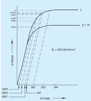
23A COLD WORKED DEFORMED BAR
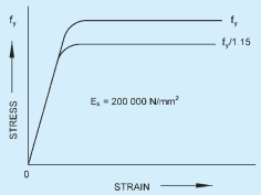
23B STEEL BAR WITH DEFINITE YIELD POINT
FIG. 23 REPRESENTATIVE STRESS-STRAIN CURVES FOR REINFORCEMENT
subjected to axial compression and bending and when there is no tension on the section shall be 0.0035 minus 0.75 times the strain at the least compressed extreme fibre.
38.2 Minimum Eccentricity
All members in compression shall be designed for the minimum eccentricity in accordance with 24.4. Where calculated eccentricity is larger, the minimum eccentricity should be ignored.
38.3 Short Axially Loaded Members in Compression
The member shall be designed by considering the assumptions given in 38.1 and the minimum eccentricity. When the minimum eccentricity as per 24.4 does not exceed 0.05 times the lateral dimension, the members may be designed by the following equation:
38.4 Compression Members with Helical Reinforcement
The strength of compression members with helical reinforcement satisfying the requirement of 38.4.1 shall be taken as 1.05 times the strength of similar member with lateral ties.
38.4.1 The ratio of the volume of helical reinforcement to the volume of the core shall not be less than:
38.5 Members Subjected to Combined Axial Load and Uniaxial Bending
A member subjected to axial force and uniaxial bending shall be designed on the basis of 38.1 and 38.2.
NOTE — The design of member subjected to combined axial load and uniaxial bending will involve lengthy calculation by trial and error. In order to overcome these difficulties interaction diagrams may be used.
38.6 Members Subjected to Combined Axial Load and Biaxial Bending
The resistance of a member subjected to axial force and biaxial bending shall be obtained on the basis of assumptions given in 38.1 and 38.2 with neutral axis so chosen as to satisfy the equilibrium of load and moments about two axes. Alternatively, such members may be designed by the following equation:
38.7 Slender Compression Members
The design of slender compression members (see 24.1.1) shall be based on the forces and the moments determined from an analysis of the structure, including the effect of deflections on moments and forces. When the effect of deflections are not taken into account in the analysis, additional moment given in 38.7.1 shall be taken into account in the appropriate direction.
38.7.1 The additional moments and shall be calculated by the following formulae: