9.1 Sampling Procedure
9.1.1 Lot
All the precast units of the same size, manufactured from the same material under similar conditions of production shall be grouped together to constitute a lot.
The number of units to be selected from each lot for dimensional requirements shall depend upon the size of the lot and shall be in accordance with col 2 and col 3 of Table 1.
The units shall be selected from the lot at random. In order to ensure the randomness of selection, reference may be made to good practice [6-7A(2)].
PART 6 STRUCTURAL DESIGN — SECTION 7 PREFABRICATION, SYSTEMS BUILDING AND MIXED/COMPOSITE CONSTRUCTION: 7A PREFABRICATED CONCRETE

FIG. 12 FLOOR SLAB-TO-WALL DETAIL WHERE DIAGONAL DOWELS CROSS THE WALL JOINT INTO THE OPPOSITE FLOOR

FIG. 13 END DETAIL OF A MONOLITHIC CONNECTION BETWEEN PRECAST CONCRETE FLOOR ELEMENT AND A PRECAST CONCRETE WALL
| Sl No. | Lot Size | First Sample Size | Second Sample Size | First Rejection Number | Second Rejection Number |
|---|---|---|---|---|---|
| (1) | (2) | (3) | (4) | (5) | (6) |
| i) | Up to 100 | 5 | 5 | 2 | 2 |
| ii) | 101 to 300 | 8 | 8 | 2 | 2 |
| iii) | 301 to 500 | 13 | 13 | 2 | 2 |
| iv) | 500 and above | 20 | 20 | 3 | 4 |

FIG. 14 (A) PLAN VIEW OF TYPICAL GROUTED OR CAST-IN-PLACE VERTICAL JOINTS IN SHEAR-WALL PANELS REINFORCED FOR HIGH SEISMIC LOADING (REFER TO ADJACENT PLAN VIEW FOR DIFFERENT CONFIGURATIONS); AND (B) VARIATIONS OF VERTICAL WALL-TO-WALL CONNECTIONS (PLAN VIEW)
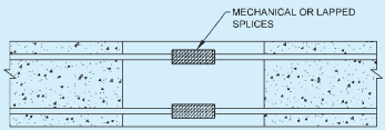
15A USING MECHANICAL OR LAPPED SPLICES
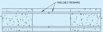
15B BUTT-WELDED REINFORCEMENT (SPECIAL PROCESS)
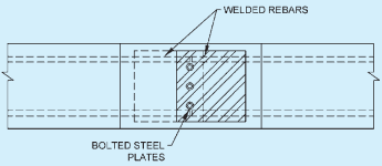
15C COMBINATION OF BOLTED PLATES AND WELDED REBARS
FIG. 15 HORIZONTAL CONNECTIONS BETWEEN BEAM OR GIRDER ENDS AT LOCATIONS OTHER THAN COLUMN FACES
PART 6 STRUCTURAL DESIGN — SECTION 7 PREFABRICATION, SYSTEMS BUILDING AND MIXED/COMPOSITE CONSTRUCTION: 7A PREFABRICATED CONCRETE
NOTE — Conduit diameter should be two to four times the bar diameter for tolerance in field erection.


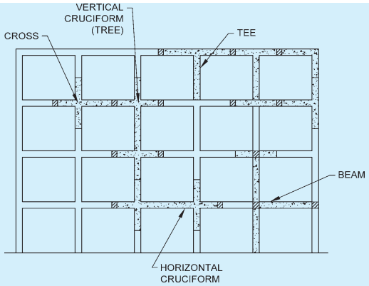
LEGEND
CAST IN PLACE CONCRETE
PRECAST CONCRETE
UNDEFINED
FIG. 16 VARIOUS CONFIGURATIONS OF PRECAST FRAME ELEMENTS
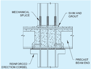
FIG. 17 CONNECTION AT BEAMS AND COLUMNS WITH CAST-IN PLACE CLOSURE
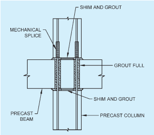
FIG. 18 COLUMN-TO-COLUMN CONNECTION THROUGH CONDUITS INSTALLED IN A BEAM
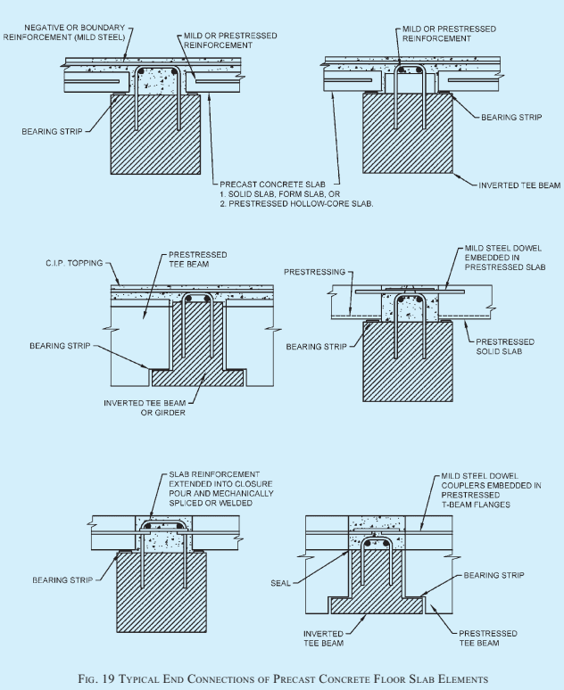
PART 6 STRUCTURAL DESIGN — SECTION 7 PREFABRICATION, SYSTEMS BUILDING AND MIXED/COMPOSITE CONSTRUCTION: 7A PREFABRICATED CONCRETE
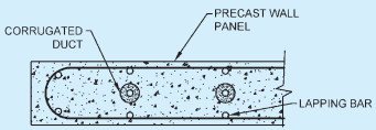
HORIZONTAL CROSS-SECTION
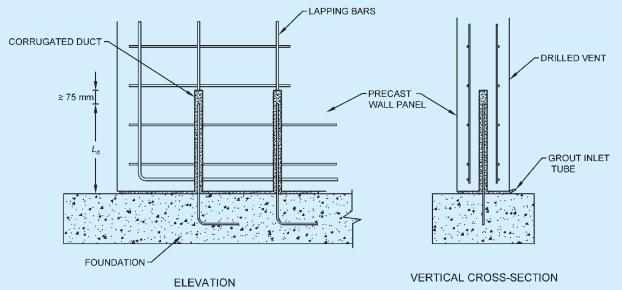
FIG. 20 WALL-FOUNDATION BEAM CONNECTION THROUGH GROUTED DUCTING
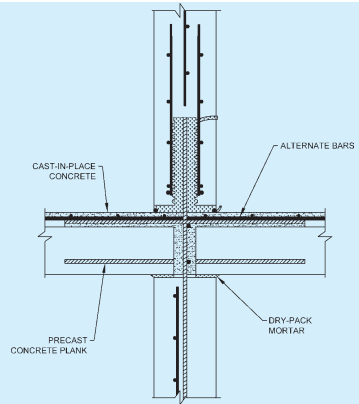
FIG. 21 INTERIOR WALL-FLOOR SLAB CONNECTION DETAIL: CONTINUOUS WALL
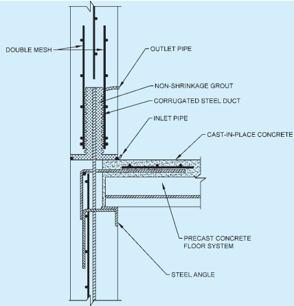
FIG. 22 EXTERIOR WALL-FLOOR SLAB CONNECTION DETAIL: PARTITIONED WALL WITH HORIZONTAL JOINT
9.1.2 Number of Tests and Criteria for Conformity
All the units selected at random in accordance with col 2 and col 3 of Table 1 shall be subjected to the dimensional requirements. A unit failing to satisfy any of the dimensional requirements shall be termed as defective. The lot shall be considered as conforming to the dimensional requirements if no defective is found in the sample, and shall be rejected if the number of defectives is greater than or equal to the first rejection number. If the number of defectives is less than the first rejection number the second sample of the same size as taken in the first stage shall be selected from the lot at random and subjected to the dimensional requirements. The number of defectives in the first sample and the second sample shall be combined and if the combined number of defectives is less than the second rejection number, the lot shall be considered as conforming to the dimensional requirements; otherwise not.
The lot which has been found as satisfactory with respect to the dimensional requirements shall then be tested for load test. For this purpose one unit shall be selected for every 300 units or part thereof. The lot shall be considered as conforming to the strength
requirement if all the units meet the requirement; otherwise not.
9.2 Testing on Individual Components
The component should be loaded for 24 h at its full span with a total load (including its own self weight) of 1.25 times . At the end of this time it should not show any sign of weakness, faulty construction or excessive deflection. Its recovery 24 h after the removal of the test load, should not be less than 75 percent of the maximum deflection recorded during the test. If prestressed, it should not show any visible cracks up to working load and should have a recovery of not less than 85 percent in 1 h.
9.3 Load Testing of Structure or Part of Structure
Loading test on a completed structure should be made if required by the specification or if there is a reasonable doubt as to the adequacy of the strength of the structure.
9.3.1 In such tests, the structure should be subjected to full dead load of the structure plus an imposed load equal to 1.25 times the specified imposed load used in design, for a period of 24 h and then the imposed load shall be removed. During the tests, vertical struts equal
PART 6 STRUCTURAL DESIGN — SECTION 7 PREFABRICATION, SYSTEMS BUILDING AND MIXED/COMPOSITE CONSTRUCTION: 7A PREFABRICATED CONCRETE
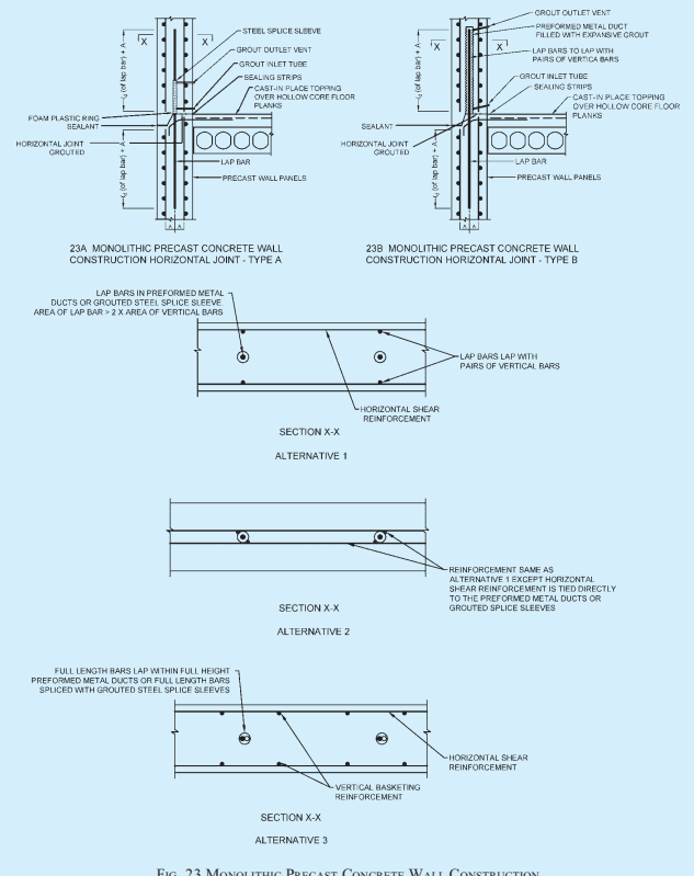
FIG. 23 MONOLITHIC PRECAST CONCRETE WALL CONSTRUCTION
in strength to take the whole load should be placed in position leaving a gap under the member.
NOTE — Dead load includes self weight of the structural members plus weight of finishes and walls or partitions, if any, as considered in the design.
9.3.1.1 If within of the removal of the load, a
reinforced concrete structure does not show a recovery of at least 75 percent of the maximum deflection shown during the 24 h under load, test loading should be repeated after a lapse of 72 h. If the recovery is less than 80 percent in second test, the structure shall be deemed to be unacceptable.

NOTE — Vertical joints shown as Types D, E and F need to be detailed with extreme care. Once the lapping bars have been overlapped the ability for lowering the wall panels over starter bars is very restricted. These details will typically work only when grouted steel splice sleeves are used to splice the vertical flexural reinforcement and when the laps of the vertical bars in the 'bandage' joints are made below floor level. Type D is not preferred because joint reinforcement and concrete infill cannot be inspected.
FIG. 24 MONOLITHIC PRECAST CONCRETE WALL CONSTRUCTION VERTICAL JOINTS
PART 6 STRUCTURAL DESIGN — SECTION 7 PREFABRICATION, SYSTEMS BUILDING AND MIXED/COMPOSITE CONSTRUCTION: 7A PREFABRICATED CONCRETE
9.4 Testing of External Precast Wall/Facade Panels for Water Tightness
Any of the testing procedures given in 9.4.1 and 9.4.2 may be followed for testing of external wall/façade panel joints for water tightness.
9.4.1 Testing Procedure 1
9.4.1.1 General
If it is deemed necessary to demonstrate that the precast façade joints are adequate to resist water penetration, a water penetration test on a full scale panel including joint mock-ups could be undertaken.
9.4.1.2 Test procedures
Mock-up panels to be tested for water tightness should be subjected to both static and cyclic pressure in accordance with standard accepted procedures. Available international testing procedures are to be modified for local conditions as follows:
a) Differential test pressure shall be 20 percent of the maximum inward design wind load but not less than 0.77 kPa; and
b) The test shall be performed with water flow rate of 3.4 litre/min/m² for 15 min.
9.4.1.3 Sampling for water penetration test
Full scale water tightness testing on precast façade panels and joints should be carried out at the rate of 0.5 percent for each type of joint and combination of panels or one for each type of joint and precast unit, whichever is the greater.
9.4.1.4 Failure criterion
The façade units or joints are deemed to have failed if signs of water seepage through the joints or through the façade unit, including signs of damp patches, are observed during the test or within the subsequent 2 h after the test.
9.4.1.5 Remedial action on failure
Upon failure of a water penetration test on a precast
façade system the cause of failure should be identified and the system revised and re-tested until a satisfactory test result is achieved. Modifications must be realistic in terms of job conditions and must maintain standards of quality and durability.
9.4.2 Testing Procedure 2
9.4.2.1 For external walls, a continuous jet of water shall be sprayed on the joint corresponding to 600 litre/h from a water hose having nozzle velocity of 2 m/s and a cone scatter of approximately 60º held at a distance of 1.2 m from the wall surface under test. The duration of the test shall not be less than 2 h. The hose shall be placed with the nozzle in line with the vertical joint and at a level of horizontal joints so that the jet cone will cover a vertical and two horizontal joints as shown in the drawings.
For external walls, the following tests shall be conducted for each building block: