A-1 MILD Steel Sheathing Ducts
Unless otherwise specified, the material shall be cold rolled cold annealed (CRCA) mild steel intended for mechanical treatment and surface refining but not for quench hardening or tempering.
The material shall be clean and free from rust and normally of bright metal finish. However, in case of use in aggressive environment galvanized or lead coated mild steel strips shall be adopted.
The thickness of metal sheathing shall not be less than 0.3 mm, 0.4 mm and 0.5 mm for sheathing ducts having internal diameter up to 50 mm, 75 mm and 90 mm, respectively. For bigger diameter of ducts, thickness of sheathing shall be based on recommendations of prestressing system supplier.
The sheathing shall conform to the requirements specified in A-3 and a test certificate shall be furnished by the manufacturer.
The joints of all sheathing shall be water tight and conform to the provisions specified in A-5.
A-2 Corrugated Hdpe Sheathing Ducts
Unless otherwise specified, the material for the ducts shall be high-density polyethylene with more than 2 percent carbon black to provide resistance to ultraviolet degradation and shall have the following properties:
| Specific density | : 0.954 g/cm3 at 23 °C |
| Yield stress | : 18.0 N/mm2 |
| Tensile strength | : 21.0 N/mm2 |
| Shore hardness D: | |
| a) 3 s | : 60 |
| b) 15 s | : 58 |
| Notch impact strength at: | |
| a) 23°C | : 10 kJ/m2 |
| b) 40°C | : 4 kJ/m2 |
| Coefficient of thermal | : 1.50 × 10⁻⁴/°C |
The thickness of the wall shall be as manufactured and after loss in the compression test, for duct size up to outer diameter.
A-3 Tests on Sheathing Ducts
a) All tests specified below shall be carried out on the same sample in the order given below.
b) At least 3 samples for one lot of supply (not exceeding length) shall be tested.
A-3.1 Workability Test
A test sample 1 100 mm long is soldered to a fixed base plate with a soft solder (see Fig. 9). The sample is then bent to a radius of 1 800 mm alternately on either
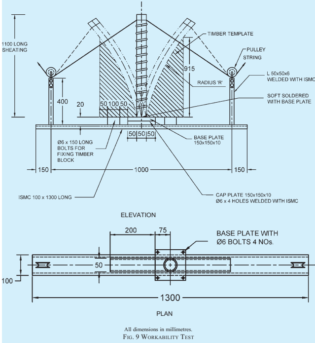
side to complete 3 cycles. Thereafter, the sealing joints will be visually inspected to verify that no failure or opening has taken place.
A-3.2 Transverse Load Rating Test
The test ensures that stiffness of the sheathing is sufficient to prevent permanent distortion during site handling.
The sample is placed on a horizontal support 500 mm long so that the sample is supported at all points of outward corrugations.
A load as specified in the table below is applied gradually at the centre of the supported portion through a circular contact surface of 12 mm diameter:
| Diameter of Sheathing mm | Load N |
|---|---|
| More than 25 up to 35 | 250 |
| more than 35 up to 45 | 400 |
| more than 45 up to 55 | 500 |
| more than 55 up to 65 | 600 |
| more than 65 up to 75 | 700 |
| more than 75 up to 85 | 800 |
| more than 85 up to 90 | 1 000 |
Couplers shall be placed so that the load is applied approximately at the centre of two corrugations (see Fig. 10). The load as specified below is applied in increments.
The sample is considered acceptable, if the permanent deformation is less than 5 percent.
A-3.3 Tension Load Test
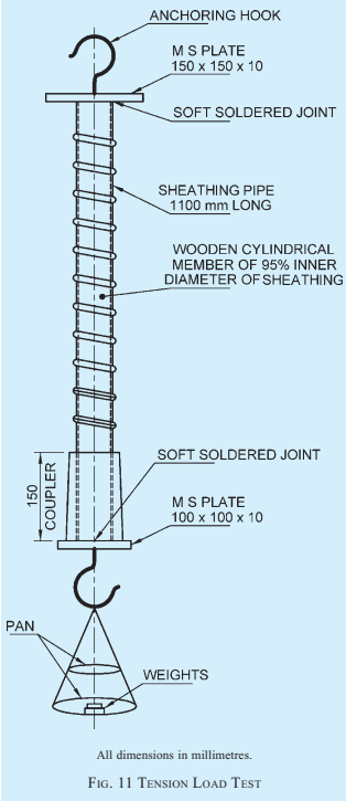
The test specimen is subjected to a tensile load. The hollow core is filled with a wooden circular piece having a diameter of 95 percent of the inner diameter of the sample to ensure circular profile during test loading (see Fig. 11).
A coupler is screwed on and the sample loaded in increments, till specified load. If no deformation of the joints nor slippage of couplers is noticed, the test shall be considered satisfactory:
| Diameter of Sheathing mm | Load N |
|---|---|
| more than 25 up to 35 | 300 |
| more than 35 up to 45 | 500 |
| more than 45 up to 55 | 800 |
| more than 55 up to 65 | 1 100 |
| more than 65 up to 75 | 1 400 |
| more than 75 up to 85 | 1 600 |
| more than 85 up to 90 | 1 800 |
A-3.4 Water Loss Test
The sample is sealed at one end. The sample is filled with water and after sealing, the end is connected to a system capable of applying a pressure of 0.05 MPa (see Fig. 12) and kept constant for 5 min; hand pump and pressure gauge or stand pipe system can be used.
The sample is accepted if the water loss does not exceed 1.5 percent of the volume. The volume is worked out as follows:
Another sample 500 mm long is sealed at one end and the volume of hollow space arrived at by pouring water from a measuring cylinder.
The computation of relative profile volume is worked out as follows:
Relative profile volume = cm /cm
A-4 Tests on Corrugated Hdpe Sheathing Ducts
The additional acceptance tests for the prestressing systems employing corrugated HDPE ducts shall cover the following two tests.
A-4.1 Bond Test
A-4.1.1 The test is carried out to establish satisfactory bond characteristics between the tendon and concrete, in the ultimate condition. The test requires the following equipment:
a) Three similarly reinforced concrete beams with a HDPE duct of length equal to 40 times the duct diameter,
b) Prestressing tendon of adequate length for stressing and for embedding in the beam,
c) Tendon anchorage system,
d) Load cells and meters, and
e) Grout constituents.
A-4.1.2 Method
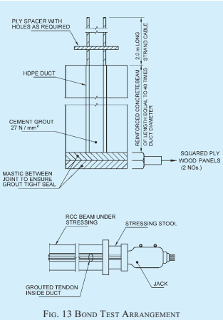
Cast an adequately reinforced beam to withstand the prestressing operation and of length to embed 40 times the diameter of duct to suit the tendon to be adopted. Introduce the strands of the tendon by spacing them parallel by means of ply-spacers as shown in Fig. 13
PART 6 STRUCTURAL DESIGN — SECTION 5 CONCRETE: 5B PRESTRESSED CONCRETE
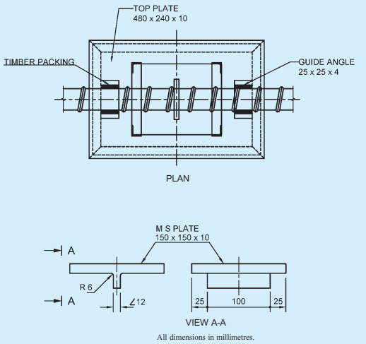
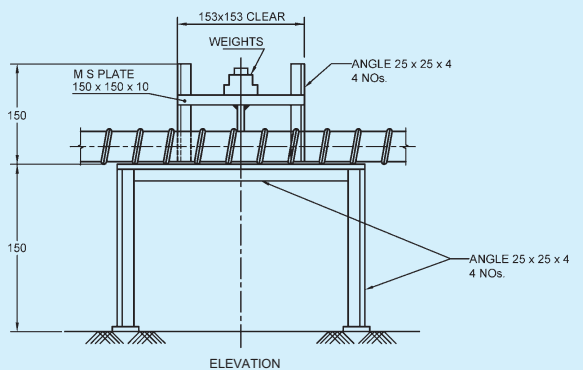
FIG. 10 TRANSVERSE LOAD RATING TEST
and fill the duct with grout of strength not less than . When the grout has attained the necessary strength, stress the tendon slowly increasing the load to the failure capacity. The failure capacity of the bond shall be at least equal to the anchorage efficiency or 0.95 of failure capacity of the tendon. At least 3 tests shall be carried out to ascertain the adequacy of the duct.
A-4.2 Compression Test for the Loss of Wall Thickness
A-4.2.1 The test is carried out to establish the wear and tear of the sheathing material and the rigidity of the duct surface against indentation and abrasion under
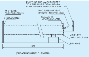
FIG. 12 TEST FOR WATER LOSS STUDY
concentrated line loading from the tendon constituents. The test requires the following equipment:
a) Three concrete blocks,
b) One long strand forming the tendon,
c) A 3 MN press,
d) A loading beam of 300 mm length to transmit 5 kN load,
e) A rubber pad for placing between the press and the beam for uniform and constant load transfer,
f) A bearing plate with a mono strand jack to pull the strand under loaded condition, and
g) A digital caliper.
PART 6 STRUCTURAL DESIGN — SECTION 5 CONCRETE: 5B PRESTRESSED CONCRETE
A-4.2.2 Method
Cast three concrete cubes of 300 mm size, of the same strength as a main structure, with half cut HDPE sheathing ducts embedded in it at the top as shown in Fig. 14. Care shall be exercised to ensure that the duct surface has uniform contact with concrete all around. Place the concrete block over the press with a 1 000 mm length of strand forming the tendon placed in the duct and apply the 5 kN uniform load gradually as shown. Pull the strand under the stressed condition by 200 mm across the duct. Repeat the test on all the 3 ducts so embedded. Measure the indentations formed in all the 3 ducts along the length of the strand, by means of digital caliper. The residual thickness of the duct shall not be less than 1.5 mm.
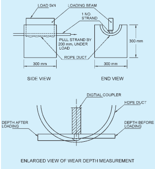
FIG. 14 COMPRESSION TEST ARRANGEMENT
A-5 Specification for Sheathing Duct Joints
The sheathing ducts shall be of the spiral corrugated type. For major projects, the sheathing ducts should preferably be manufactured at the project site utilizing appropriate machines. With such an arrangement, long lengths of sheathing ducts may be used with consequent reduction in the number of joints and couplers.
Where sheathing duct joints are unavoidable, such joints shall be made cement slurry tight by the use of corrugated threaded sleeve couplers which can be tightly screwed on to the outer side of the sheathing ducts. A heat-shrink coupler could also be used if suitable.
Typical details of a sleeve coupler is shown in Fig. 15. The length of the coupler should not be less than 150 mm but should be increased upto 200 mm, wherever practicable. The joints between the ends of the coupler and the duct shall be sealed with adhesive sealing tape to prevent penetration of cement slurry during concreting. The couplers of adjacent ducts should be staggered wherever practicable. As far as possible, couplers should not be located in curved zones. The corrugated sleeve couplers are being conveniently manufactured using the sheath making machine with the next higher size of die set.
The heat-shrink coupler (see Fig. 16) is supplied in the form of bandage rolls which can be used for all diameters of sheathing ducts. The bandage is coated on the underside with a heat sensitive adhesive so that after heating the bandage material shrinks on to the sheathing duct and ensures formation of a leak proof joint, without the need for extra taping or support in the form of corrugated sleeve couplers. The heating is effected by means of a soft gas flame.
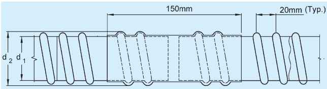
FIG. 15 TYPICAL DETAILS OF A SLEEVE COUPLER
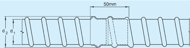
FIG. 16 TYPICAL DETAILS OF HEAT-SHRINK COUPLERE