Members subjected to predominant bending shall have adequate design strength to resist bending moment, shear force, and concentrated forces imposed upon and their combinations. Further, the members shall satisfy
the deflection limitation presented in Section 6(e), as serviceability criteria. Member subjected to other forces in addition to bending or biaxial bending shall be designed in accordance with Section 6(j).
14.1.1 Effective Span of Beams
The effective span of a beam shall be taken as the distance between the centres of the supports, except where the point of application of the reaction is taken as eccentric at the support, when it shall be permissible to take the effective span as the length between the assumed lines of the reactions.
14.2Design Strength in Bending (Flexure)
The design bending strength of beam, adequately supported against lateral torsional buckling (laterally supported beam) is governed by the yield stress (see 14.2.1). When a beam is not adequately supported against lateral buckling (laterally un-supported beams) the design bending strength may be governed by lateral torsional buckling strength (see 14.2.2).
The factored design moment, M at any section, in a beam due to external actions, shall satisfy
M≤Md
where
Md= design bending strength of the section, calculated as given in 14.2.1.2.
14.2.1 Laterally Supported Beam
A beam may be assumed to be adequately supported at the supports, provided the compression flange has full lateral restraint and nominal torsional restraint at supports supplied by web cleats, partial depth end plates, fin plates or continuity with the adjacent span. Full lateral restraint to compression flange may be assumed to exist if the frictional or other positive restraint of a floor connection to the compression flange of the member is capable of resisting a lateral force not less than 2.5 percent of the maximum force in the compression flange of the member. This may be considered to be uniformly distributed along the flange, provided gravity loads constitute the dominant loading on the member and the floor construction is capable of resisting this lateral force.
The design bending strength of a section which are not susceptible to web buckling under shear before yielding (where d/tw≤67e) shall be determined according to 14.2.1.2.
14.2.1.1 Section with webs susceptible to shear buckling before yielding
When the flanges are plastic, compact or semi-compact but the web is susceptible to shear buckling before
yielding (see 14.4.2.1), the design bending strength shall be calculated using one of the following methods:
a) The bending moment and axial force acting on the section may be assumed to be resisted by flanges only and the web is designed only to resist shear (see 14.4).
b) The bending moment and axial force acting on the section may be assumed to be resisted by the whole section. In such a case, the web shall be designed for combined shear and normal stresses using simple elastic theory in case of semi-compact webs and simple plastic theory in the case of compact and plastic webs.
14.2.1.2 When the factored design shear force does not exceed 0.6Vd , where Vd is the design shear strength of the cross-section (see 14.4), the design bending strength, Md shall be taken as:
Md=βbZpfy/γm0
To avoid irreversible deformation under serviceability loads, Md shall be less than 1.2Zefy/γm0 in case of simply supported and 1.5Zefy/γm0 in case of cantilever beams;
where
βb=1.0for plastic and compact sections;
=Ze/Zpfor semi - compact sections;
Zp,Ze=plastic and elastic section moduli of the cross-section, respectively;
fy= yield stress of the material; and
γm0=partial safety factor (see 11.4.1).
14.2.1.3 When the design shear force (factored), V exceeds 0.6Vd, where Vd is the design shear strength of the cross-section (see 14.4) the design bending strength, Md shall be taken as:
Md=Mdv
where
Mdv= design bending strength under high shear as defined in 15.2.
14.2.1.4 Holes in the tension zone
a) The effect of holes in the tension flange, on the design bending strength need not be considered if
(Anf/Agf)≥(fs/fu)(γm1/γm0)/0.9
where
Anf/Agf = ratio of net to gross area of the flange in tension;
fy/fu = ratio of yield and ultimate stress of the material; and
γml/γm0= ratio of partial safety factors
against ultimate to yield stress (see 11.4.1).
When the Anf/Agf does not satisfy the above requirement, the reduced effective flange area, Aef satisfying the above equation may be taken as the effective flange area in tension, instead of Agf .
b) The effect of holes in the tension region of the web on the design flexural strength need not be considered, if the limit given in 14.2.1.4(a) above is satisfied for the complete tension zone of the cross-section, comprising the tension flange and tension region of the web.
c) Fastener holes in the compression zone of the cross-section need not be considered in design bending strength calculation, except for oversize and slotted holes or holes without any fastener.
14.2.1.5 Shear lag effects
The shear lag effects in flanges may be disregarded provided:
a) For outstand elements (supported along one edge), bo≤Lo/20; and
b) For internal elements (supported along two edges), bi≤Lo/10.
where
Lo= length between points of zero moment (inflection) in the span,
bo= width of the flange with outstand, and
bi = width of the flange as an internal element
Where these limits are exceeded, the effective width of flange for design strength may be calculated using specialist literature, or conservatively taken as the value satisfying the limit given above.
14.2.2Laterally Unsupported Beams
Resistance to lateral torsional buckling need not be checked separately (member may be treated as laterally supported, see 14.2.1) in the following cases:
a) Bending is about the minor axis of the section,
b) Section is hollow (rectangular/ tubular) or solid bars, and
c) In case of major axis bending, λLT (as defined herein) is less than 0.4.
The design bending strength of laterally unsupported beam as governed by lateral torsional buckling is given by:
Md=βbZpfbd
where
βb=1.0 for plastic and compact sections;
=Ze/Zp for semi-compact sections;
Zp,Ze= plastic section modulus and elastic section modulus with respect to extreme compression fibre;
fbd = design bending compressive stress, obtained as given below [see Tables 13(a) and 13(b)];
fbd=cLT,y/γm0;and
χLT= bending stress reduction factor to account for lateral torsional buckling, given by:
χLT={ϕLT+[ϕLT2−λLT2]0.5}1≤1.0
ϕLT=0.5[1+αLT(λLT−0.2)+λLT2]
αLT , the imperfection parameter is given by:
αLT=0.21 for rolled steel section
αLT=0.49 for welded steel section
The non-dimensional slenderness ratio, lLT, is given by:
fcr,b of non-slender rolled steel sections in the above equation may be approximately calculated from the values given in the Table 14, which has been prepared using the following equation:
The following simplified equation may be used in the case of prismatic members made of standard rolled I-sections and welded doubly symmetric I-sections, for calculating the elastic lateral buckling moment, Mcr (see Table 14).
It = torsional constant ∑biti3/3 for open section;
Iw = warping constant;
Iy,ry=moment of inertia and radius of gyration, respectively about the weaker axis;
LLT = effective length for lateral torsional buckling (see 14.3);
hf = centre-to-centre distance between flanges; and
tf = thickness of the flange.
Mcr for different beam sections, considering loading, support condition, and asymmetric section, shall be more accurately calculated using the method given in Annex D. The above equations for calculating Mcr may be conservatively used for channel sections.
14.3Effective Length for Lateral Torsional Buckling
14.3.1 For simply supported beams and girders of span length, L, where no lateral restraint to the compression flanges is provided, but where each end of the beam is restrained against torsion, the effective length LLT of the lateral buckling to be used in 14.2.2.1 shall be taken as in Table 15.
In simply supported beams with intermediate lateral restraints against lateral torsional buckling, the effective length for lateral torsional buckling, LLT to be used in 14.2.2.1, shall be taken as the length of the relevant segment in between the lateral restraints. In the case of intermediate partial lateral restraints, the effective length, LLT shall be taken as equal to 1.2 times the length of the relevant segment in between the partial lateral restraints.
Restraint against torsional rotation at supports in these beams may be provided by,
a) web or flange cleats, or
b) bearing stiffeners acting in conjunction with the bearing of the beam, or
c) lateral end frames or external supports providing lateral restraint to the compression flanges at the ends, or
d) their being built into walls.
PART 6 STRUCTURAL DESIGN — SECTION 6 STEEL
Sl No.
Conditions of Restraint at Supports
Loading Condition
Torsional restraint(2)
Warping Restraint(3)
Normal(4)
Destabilizing(5)
i)
Fully restrained
Both flangesfully restrained
0.70 L
0.85 L
ii)
Fully restrained
Only compressionflange fullyrestrained
0.75 L
0.90 L
iii)
Fully restrained
Both flangespartiallyrestrained
0.80 L
0.95 L
iv)
Fully restrained
Only compressionflange partiallyrestrained
0.85 L
1.00 L
v)
Fully restrained
No restraint in both flanges
1.00 L
1.20 L
vi)
Partially restrained by bottom flangesupport connection
No restraint in both flanges
1.0 L+2D
1.2 L+2D
vii)
Partially restrained bybottom flangebearing support
No restraint in both flanges
1.2 L+2D
1.4 L+2D
NOTES
1 Torsional restraint prevents rotation about the longitudinal axis.
2 Warping restraint prevents rotation of the flange in its plane.
3 D is the overall depth of the beam.
4 In case of continuous beams, L shall be taken as the distance between points of inflection, and the restraint conditions at the points of inflection should be considered.
14.3.2 For beams, which are provided with members giving effective lateral restraint to the compression flange at intervals along the span, in addition to the end torsional restraint required in 14.3.1, the effective length for lateral torsional buckling shall be taken as the distance, centre-to-centre of the restraint members in the relevant segment under normal loading condition and 1.2 times this distance, where the load is not acting on the beam at or above the shear centre and towards the shear centre, so as to have destabilizing effect during lateral torsional buckling deformation.
14.3.3 For cantilever beams of projecting length L, the effective length LLT to be used in 14.2.2.1 shall be taken as in Table 16 for different support conditions.
14.3.4 Where a member is provided intermediate lateral supports to improve the lateral buckling strength, these restraints should have sufficient strength and stiffness to prevent lateral movement of the compression flange at that point, relative to the end
14.3.5 Purlins adequately restrained by sheeting need not be normally checked for the restraining forces required by rafters, roof trusses or portal frames that carry predominately roof loads provided there is bracing of adequate stiffness in the plane of rafters or roof sheeting which is capable of acting as a stressed skin diaphragm.
14.3.6 In case of beams with double curvature bending, adequate direct lateral support to the compression flange in the hogging moment region may be provided as given above for simply supported beam. The effect of support to the tension (top) flange in the hogging moment region on lateral restraint to the compression flange may be considered as per specialist literature.
14.4Shear
The factored design shear force, V, in a beam due to external actions shall satisfy
V≤Vd
where
Vd= design strength
=Vn/γm0
where
γm0=partial safety factor against shear failure (see 11.4.1).
The nominal shear strength of a cross-section, Vn , may be governed by plastic shear resistance (see 14.4.1) or strength of the web as governed by shear buckling (see 14.4.2).
14.4.1 The nominal plastic shear resistance under pure shear is given by:
∣Vn=Vp∣
where
Vp=3Avfyw
Av= shear area; and
fyw= yield strength of the web.
14.4.1.1 The shear area may be calculated as given below:
a) I-and channel sections:
Major Axis Bending:
tw
tw
Minor Axis Bending:
Hot-rolled or welded : 2b tf
b) Rectangular hollow sections of uniform thickness:
Loaded parallel to depth (h) : A h/(b+h)
Loaded parallel to width (b) : A b/(b+h)
c) Circular hollow tubes of uniform : 2A/π thickness
d) Plates and solid bars : A where
A= cross-section area,
b = overall breadth of tubular section, breadth of I-section flanges,
d= clear depth of the web between flanges,
h= overall depth of the section,
tf= thickness of the flange, and
tw= thickness of the web.
PART 6 STRUCTURAL DESIGN — SECTION 6 STEEL
NOTE — Fastener holes need not be accounted for in plastic design shear strength calculation provided that:
Avn≥(fj/fu)(γmi/γnf0)Av/0.9
If Avn does not satisfy the above condition, the effective shear area may be taken as that satisfying the above limit. Block shear failure criteria may be verified at the end connections. Section 6(j) may be referred to for design strength under combined high shear and bending.
14.4.2 Resistance to Shear Buckling
14.4.2.1 Resistance to shear buckling shall be verified as specified, when
d/tw>67εw for a web without stiffeners, and
>67εw5.35Kvfor a web with stiffeners
where
Kv= shear buckling coefficient (see 14.4.2.2), and
εw=250/fyw
14.4.2.2 Shear buckling design methods
The nominal shear strength, Vn, of webs with or without intermediate stiffeners as governed by buckling may be evaluated using one of the following methods:
a) Simple post-critical method — The simple post critical method, based on the shear buckling strength can be used for webs of I-section girders, with or without intermediate transverse stiffener, provided that the web has transverse stiffeners at the supports. The nominal shear strength is given by:
∣Vn=Vcr∣
where
Vcr= shear force corresponding to web buckling
=Avτb
where
τb= shear stress corresponding to web buckling, determined as follows:
when λw≤0.8, τb=fyw/3
when 0.8<λw<1.2,
τb=[1−0.8(λw−0.8)](fyw/3)
when λw≥1.2, τb=fyw/(3λw2)
where
λw= Non-dimensional web slenderness ratio for shear buckling stress, given by:
λw=fyw/(3τcr,e)
tcr,e= elastic critical shear stress of the web
=12(1−μ2)[d/tw]2Kvπ2E
where
μ=Poisson’s ratio, and
Kv=5.35 when transverse stiffeners are provided only at supports
=4.0+5.35/(c/d)2forc/d<1.0
=5.35+4.0/(c/d)2forc/d≥1.0
where c,d are the spacing of transverse stiffeners and depth of the web, respectively.
b) Tension field method — The tension field method, based on the post-shear buckling strength, may be used for webs with intermediate transverse stiffeners, in addition to the transverse stiffeners at supports, provided the panels adjacent to the panel under tension field action, or the end posts provide anchorage for the tension fields and if c/d≥1.0 , where c, d are the spacing of transverse stiffeners and depth of the web, respectively.
In the tension field method, the nominal shear resistance, Vn, is given by:
Vn=Vtf
where
Vtf=[Avτb+0.9wtftwfvsinϕ]≤Vp
where
τb= shear stress corresponding to buckling of web 14.4.2.2(a);
fv= yield strength of the tension field obtained
from[fyw2−3τb2+ψ2]0.5−ψ;
ψ=1.5τbsin2ϕ;
ϕ= inclination of the tension field nearly
=tan−11.5(cd);
wtf= width of the tension field, given by:
=dcosϕ−(c−sc−st)sinϕ;
fyw= yield stress of the web;
d= depth of the web;
c = spacing of transverse stiffeners in the web; and
sc,st= anchorage lengths of tension field along the compression and tension flange, respectively, obtained from:
where
s=sinϕ2[fywtwMfr]0.5≤c
Mfr= reduced plastic moment capacity of the respective flange plate (disregarding any edge stiffener) after accounting for the axial force, Nf in the flange, due to overall bending and any external axial force in the cross-section, and is calculated as :
Mfr=0.25bftf2fyf[1−{Nf/(bftffyf/γm0)}2]
where
bf,tf=width and thickness of the relevant flange, respectively; and
fyf= yield stress of the flange.
14.5Stiffened Web Panels
14.5.1 End Panels Design (see Fig.12)
The girders in which the interior panel (panel A) is designed using tension field action, the end panels shall be designed using only simple post critical method, according to 14.4.2.2(a).
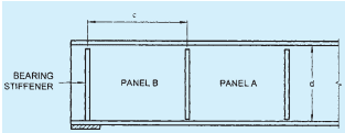
Additionally, the end panel along with the stiffeners should be checked as a beam spanning between the flanges to resist a shear force, Rtf, and a moment, Mtf, due to tension field forces as given in 14.5.3. Further, end stiffener should be capable of resisting the reaction plus a compressive force due to the moment, equal to Mtf [see Fig. (12)].
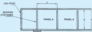
14.5.2 End Panels Designed Using Tension Field Action (see Fig. 13 and Fig. 14)
The end panel (Panel A) shall be designed according to 14.4.2.2(b).
Additionally it should be provided with an end post consisting of a single or double stiffener (see Fig. 13 and Fig. 14), satisfying the following.
a) Single stiffener (see Fig. 13) — The top of the end post should be rigidly connected to the flange using full strength welds.
The end post should be capable of resisting the reaction plus a moment from the anchor forces equal to 2/3Mtf due to tension field forces, where Mtf is obtained from 14.5.3. The width and thickness of the end post are not to exceed the width and thickness of the flange.
b) Double stiffener (see Fig. 14)— The end post should be checked as a beam spanning between the flanges of the girder and capable
Table 16Effective Length, L_{\mathrm{LT}} for Cantilever of Length, L (Clause 14.3.3)
Restraint Condition
Loading Conditions
At Support At top
Normal Destabilizing
(2)
(3)
(4)
(5)
a) Continuous, with lateral restraint to top flange
i) Freeii) Lateral restraint to top flangeiii) Torsional restraintiv) Lateral and torsional restraint
3.0L2.7L2.4L2.1L
7.5L7.5L4.5L3.6L
b) Continuous, with partial torsional restraint
i) Freeii) Lateral restraint to top flangeiii) Torsional restraintiv) Lateral and torsional restraint
2.0L1.8L1.6L1.4L
5.0L5.0L3.0L2.4L
c) Continuous, with lateral and torsional restraint
i) Freeii) Lateral restraint to top flangeiii) Torsional restraintiv) Lateral and torsional restraint
1.0L0.9L0.8L0.7L
2.5L2.5L1.5L1.2L
d) Restrained laterally, torsionally and against rotation on plan
i) Freeii) Lateral restraint to top flangeiii) Torsional restraintiv) Lateral and torsional restraint
0.8L0.7L0.6L0.5L
1.4L1.4L0.6L0.5L
Top restraint conditions
i) Free
ii) Lateral restraint to top flange
iii) Torsional restraint
iv) Lateral and torsional restraint
PART 6 STRUCTURAL DESIGN — SECTION 6 STEEL
of resisting a shear force Rtf and a moment, Mtf due to the tension field forces as given in 14.5.3.
14.5.3 Anchor Forces
The resultant longitudinal shear, Rtf, and a moment Mtf from the anchor of tension field forces are evaluated as given below:
Rtf=2HqandMtf=10Hqd
where
Hq=1.25Vp(1−VpVcr)1/2
Vp=3dtfy
d=web depth,
If the actual factored shear force, V in the panel designed using tension field approach is less than the shear strength, Vtf as given in 14.4.2.2(b), then the values of
Hq may be reduced by the ratio Vtf−VcrV−Vcr
where
Vtf= basic shear strength for the panel utilizing tension field action as given in 14.4.2.2(b), and
Vcr= critical shear strength for the panel designed utilizing tension field action as given in 14.4.2.2(a).
FIG. 14 END PANEL DESIGNED USING TENSION FIELD ACTION (DOUBLE STIFFENER)
NOTES
1 Panel A is designed utilizing tension field action as given in 14.4.2.2(b).
2 Panel B is designed using simple post critical method as given in 14.4.2.2(a).
3 Bearing stiffener is designed for the compressive force due to bearing plus compressive force due to the moment Mtf as given in 14.5.3.
FIG. 12 END PANEL DESIGNED NOT USING TENSION FIELD ACTION
NOTES
1 Panel A is designed utilizing tension field action as given in 14.4.2.2(b).
2 Bearing stiffener and end post is designed for combination of compressive loads due to bearing and a moment equal to 2/3Mtf as given in 14.5.3.
FIG. 13 END PANEL DESIGNED USING TENSION FIELD ACTION (SINGLE STIFFENER)
NOTES
1 Panel A is designed utilizing tension field action as given in 14.4.2.2(b).
2 Bearing stiffener is designed for compressive force due to bearing as given in 14.4.2.2(a).
3 End post is designed for horizontal shear Rtf and moment Mtf as given in 14.5.3.
14.5.4 Panels with Openings
Panels with opening of dimension greater than 10 percent of the minimum panel dimension should be designed without using tension field action as given in 14.4.2.2(b). The adjacent panels should be designed as an end panel as given in 14.5.1 or 14.5.2, as appropriate.
14.6Design of Beams and Plate Girders with Solid Webs
14.6.1 Minimum Web Thickness
The thickness of the web in a section shall satisfy the following requirements:
14.6.1.1 Serviceability requirement
a) when transverse stiffeners are not provided,
twd≤200εw (web connected to flanges along both longitudinal edges)
twd≤90εw (web connected to flanges along one longitudinal edge only),
b) when only transverse stiffeners are provided (in webs connected to flanges along both longitudinal edges),
when 3d≥c≥d
twd≤200εw
when 0.74d≥c<d
twc≤200εw
when c<0.74d
twd≤270εw
when c>3d, the web shall be considered as unstiffened,
c) when transverse stiffeners and longitudinal stiffeners at one level only are provided (0.2 d from compression flange) according to 14.7.13(a),
when 2.4d≥c≥d
twd≤250εw
when 0.74d≤c≤d
twc≤250εw
when c < 0.74 d
twd≤340εw
d) when a second longitudinal stiffener (located at neutral axis is provided)
twd≤400εw
where
d= depth of the web,
tw= thickness of the web,
c = spacing of transverse stiffener (see Fig. 12 and Fig. 13),
εw= yield stress ratio of web =fyw250 and
fyw= yield stress of the web.
14.6.1.2 Compression flange buckling requirement
In order to avoid buckling of the compression flange into the web, the web thickness shall satisfy the following:
a) When transverse stiffeners are not provided,
twd≤345εf2
b) When transverse stiffeners are provided, and
i) when c≥1.5d
twd≤345εf2
ii) when c<1.5d
twd≤345εf
where
d= depth of the web,
tw= thickness of the web,
c = spacing of transverse stiffener (see Fig. 12 and Fig. 13),
εf= yield stress ratio of flange =fyf250 , and
fyf= yield stress of compression flange.
14.6.2 Sectional Properties
14.6.2.1 The effective sectional area of compression flanges shall be the gross area with deductions for excessive width of plates as specified for compression members [see Section 6(g)] and for open holes occurring in a plane perpendicular to the direction of stress at the section being considered (see 14.2.1.4).
The effective sectional area of tension flanges shall be the gross sectional area with deductions for holes as specified in 14.2.1.4.
The effective sectional area for parts in shear shall be taken as specified in 14.4.1.1.
14.6.3 Flanges
14.6.3.1 In riveted or bolted construction, flange angles shall form as large a part of the area of the flange as practicable (preferably not less than one-third) and the number of flange plates shall be kept to a minimum.
In exposed situations, where flange angles are used, at least one plate of the top flange shall extend over the full length of the girder, unless the top edge of the web is machined flush with the flange angles. Where two or more flange plates are used, tacking rivets shall be provided, if necessary to comply with the requirements of Section 6(k).
Each flange plate shall extend beyond its theoretical cut-off point, and the extension shall contain sufficient rivets, bolts or welds to develop in the plate, the load calculated for the bending moment on the girder section
PART 6 STRUCTURAL DESIGN — SECTION 6 STEEL
(taken to include the curtailed plate) at the theoretical cut-off point.
The outstand of flange plates, that is the projection beyond the outer line of connections to flange angles, channel or joist flanges or in the case of welded constructions their projection beyond the face of the web or tongue plate, shall not exceed the values given in 9.7.2 (see Table 2).
In the case of box girders, the thickness of any plate, or the aggregate thickness of two or more plates, when these plates are tacked together to form the flange, shall satisfy the requirements given in 9.7.2 (see Table 2).
14.6.3.2 Flange splices
Flange splices should preferably, not be located at points of maximum stress. Where splice plates are used, their area shall be not less than 5 percent in excess of the area of the flange element spliced; their centre of gravity shall coincide, as nearly as possible, with that of the element spliced. There shall be enough bolts, rivets or welds on each side of the splice to develop the load in the element spliced plus 5 percent but in no case should the strength developed be less than 50 percent of the effective strength of the material spliced. In welded construction, flange plates shall be joined by complete penetration butt welds, wherever possible. These butt welds shall develop the full strength of the plates.
14.6.3.3 Connection of flanges to web
The flanges of plate girders shall be connected to the web by sufficient rivets, bolts or welds to transmit the maximum horizontal shear force resulting from the bending moment gradient in the girder, combined with any vertical loads which are directly applied to the flange. If the web is designed using tension field method as given in 14.4.2.2 b), the weld should be able to transfer the tension field stress, fyw acting on the web.
14.6.3.4 Bolted/Riveted construction
For girders in exposed situations and which do not have flange plates for their entire length, the top edge of the web plate shall be flush with or above the angles, and the bottom edge of the web plate shall be flush with or set back from the angles.
14.6.3.5 Welded construction
The gap between the web plates and flange plates shall be kept to a minimum and for fillet welds shall not exceed 1 mm at any point before welding.
14.6.4 Webs
14.6.4.1 Effective sectional area of web of plate girder
The effective cross-sectional area shall be taken as the full depth of the web plate multiplied by the thickness.
NOTE — Where webs are varied in thickness in the depth of the section by the use of tongue plates or the like, or where the proportion of the web included in the flange area is 25 percent or more of the overall depth, the above approximation is not permissible and the maximum shear stress shall be computed on theory.
14.6.4.2 Splices in webs
Splices and cutouts for service ducts in the webs should preferably not be located at points of maximum shear force and heavy concentrated loads.
Splices in the webs of the plate girders and rolled sections shall be designed to resist the shears and moments at the spliced section (see Annex E).
In riveted or bolted construction, splice plates shall be provided on each side of the web. In welded construction, web splices shall preferably be made with complete penetration butt welds.
14.6.4.3 Where additional plates are required to augment the strength of the web, they shall be placed on each side of the web and shall be equal in thickness. The proportion of shear force assumed to be resisted by these plates shall be limited by the amount of horizontal shear which they can transmit to the flanges through their fastenings, and such reinforcing plates and their fastenings shall be carried up to the points at which the flange without the additional plates is adequate.