Every building should be so designed, constructed, equipped, maintained, and operated as to provide adequate means of egress to avoid undue danger to the life and safety of the occupants from fire, smoke, fumes, or panic during the time period necessary for escape.
For high occupancy areas, it may be required to have annunciation, announcements, and voice guided/aided system to direct the occupants towards safe egress routes, areas of comparative safety or exits, and to avoid situation of panic during distress.
Every main occupancy may have certain occupancies which may be incidental to the main occupancy. The exit requirements pertaining to such incidental occupancies from the floor of the occupancy to the level of exit discharge should be calculated to meet the requirement of the actual occupancy of such type, to ensure adequate means of egress of the occupants.
See also good practice [F(31)] for accessibility for elderly and persons with disabilities, for various requirements for enabling a smooth and safe egress.
4.2General Exit Requirements
4.2.1 Fire exits are unobstructed component of means of egress which is between the exit access and the exit discharge or public way. Exit components include exterior exit doors at the level of exit discharge, interior exit stairways (pressurised), exit stairway with external wall (pressurised or naturally ventilated), exterior exit stairways, exit passageways, and exterior exit ramps. Fire exits should be provided with panic bar to facilitate entry of occupant into fire exit.
An exit may also include a horizontal exit leading to an adjoining building/fire compartment having its further access to unlocked/public exit at the same level.
4.2.2 Unless otherwise specified, lifts, escalators, moving walks and revolving doors should not be considered as fire exits and should not constitute any part of the required fire exit.
4.2.3 Every fire exit, exit passageway and exit discharge should be continuously maintained free of all obstructions or impediments to full use in the case of fire or other emergency.
4.2.4 Every building having human occupancy should be provided with fire exits sufficient to permit safe egress of occupants, in case of fire or other emergency.
4.2.5 In every building or structure, fire exits should comply with the minimum requirements of this Part, except those not accessible for general public use.
4.2.6 No building should be so altered as to reduce the number, width, or protection of fire exits to less than that required.
4.2.7 For non-naturally ventilated areas (that is, pressurized areas), fire doors with 120 min fire resistance rating should be provided and particularly at the entrance to lift lobby and stair well where a 'funnel or flue effect' may be created, inducing an upward spread of fire, to prevent spread of fire and smoke.
4.2.8 Fire exits should be so arranged that they may be reached without passing through another occupied unit/passage in others control if they pose challenge or restriction in means of egress.
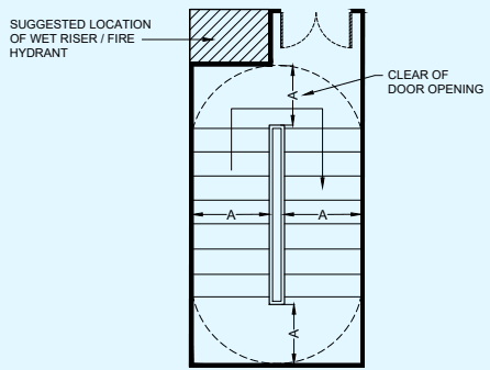
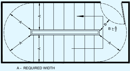
4.2.9 Doors in fire exits should open in the direction of exit. In case of assembly buildings (Group D) and institutional buildings (Group C-1), exit door should not open immediately upon a flight of stair and all such entries to the stair should be through a landing, so that such doors do not impede movement of people descending from a higher floor when fully opened (see Fig. 7A). While for other occupancies, such doors should not reduce the pathway in the landing by more than half the width of such staircase (see Fig. 7B). Over- head or sliding doors should not be installed.
4.2.10 At least half of the required exit stairs from upper floors (rounded to the next higher number) should discharge directly to the exterior or through exit passageways. For buildings less than 60 m in height, firefighting
shaft should be planned having one side on the external wall and discharging directly to the exterior. In the case of tall buildings (60 m and above), where structural design requires the location of firefighting shaft along with the structural core members, firefighting shaft(s) in the building should discharge directly to the exterior (through exit passageway).
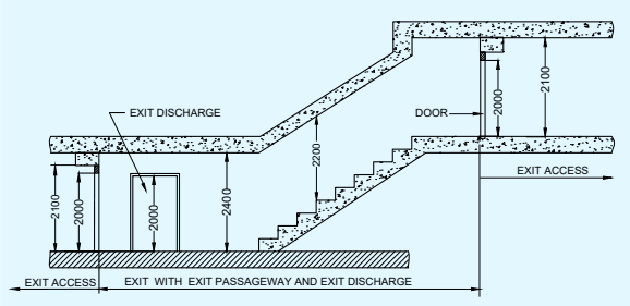
4.2.11 Unless otherwise specified, all the fire exits and exit passageways to exit discharge should have a clear ceiling height of at least 2.4 m. However, the height of fire exit door should be at least 2.0 m (see Fig. 8).
4.2.12 Where changes in elevation of more than 300 mm are encountered in the exits, ramps or sloped surfaces should be used with handrails and floor finish materials that contrast with the adjacent finish materials.
NOTE DOOR WIDTH SHALL BE BASON TYPE OF OCCUPANCY
7A MINIMUM REQUIRED UNOBSTRUCTED CLEARANCE WITH DOOR LEAF ENCROACHING ON LANDING IN INSTITUTIONAL AND ASSEMBLY BUILDING
7B MINIMUM REQUIRED UNOBSTRUCTED CLEARANCE WITH DOOR LEAF ENCROACHING ON LANDING
FIG. 7 DOOR LOCATION AT LANDING IN FIRE EXITS
FIG. 8 MINIMUM HEAD ROOM MEASUREMENT
4.2.13 The capacity of the means of egress required from any storey of the building should not be reduced along the path of egress travel until arrival to the exit discharge.
4.2.14 The lifts, escalators, moving walks, turnstiles and revolving doors should not be considered in determining the required capacity of means of egress for the individual floor(s) or the building.
4.2.15 Turnstiles or similar devices that restrict travel to one direction or that are used to restrict unauthorized entry should not be so placed as to obstruct any required means of egress. Alternative door openings of required exit width should be available within 3 m of such devices, if installed.
4.2.16 Suitable means should be provided so that all access-controlled exit doors, turnstiles, boom barriers and other such exits should automatically operate to open mode during emergencies like fire, smoke, acts of terrorism, etc, so that people can safely and quickly egress into safe areas outside. If required, a master controlling device may be installed at a strategic location to achieve this.
4.2.17 Penetrations into and openings through fire exit are prohibited except those necessary, like for the fire protection piping, ducts for pressurization and similar life safety services. Such openings as well as vertical passage of shaft through floors should be protected by passive systems, {see accepted standard [F(34)]}.
4.2.18 Walking surfaces in exit access should comply with the following requirements for smooth exit:
a) Walking surfaces should be nominally level;
b) The slope of walking surface in the direction of travel should not exceed 1 in 20 unless the ramp requirements are met (see 4.4.2.4.3.5);
c) Slope perpendicular to the direction of travel should not exceed 1 in 48; and
d) Walking surfaces should be slip-resistant along the entire path of travel.
4.2.19 Basement
4.2.19.1 The basement should not be used for hazardous and vulnerable activities, like sleeping purposes, class rooms, hazardous industries, restaurant kitchen (see also 4.7.9), battery rooms, UPS rooms, fuel oil storage, etc However, the State Authorities may prescribe the list of such activities based on their own assessment. Basements should have smoke ventilation systems, high-density sprinkler systems, and redundant/enclosed exits.
4.2.19.2 The fire exits in a basement should be sufficient to provide for the capacity of the basement occupancy as determined in accordance with 4.4.2.1. In no case should there be fewer than two independent basement exits.
4.2.19.3 Basements with incidental occupancies to the main occupancy should be planned with exit requirements for the actual occupancy within the basement.
4.2.19.4 Where a basement is used for car parking and also there is direct approach from any occupancy above to the basement, door openings leading to the basement should be protected with fire doors with 120 min fire resistance rating, except for exit discharge doors from the basements.
4.2.19.5 Basements should have a minimum clear height of 3.4 m towards effective performance in the event of fire/smoke. Impulse or duct ventilation system needs to be designed to ensure removal of hot gases and smoke from each compartment to achieve reasonable visibility and heat reduction for firefighting operations.
4.4Egress Components
Egress components to be considered are the number of exits to which access is provided, capacity of exit access, travel distance to a fire exit, the obviousness of the direction to a fire exit, and any hindrance including due to security issues involved.
4.4.1 Exit Access
a) A common path of travel is desirable in exit access which leads to two independent directions to separate fire exits;
b) Capacity of Exit Access — The width of corridors, aisles or ramps required for exit access should be sufficient to ensure a smooth flow of occupants to the fire exit. Where a corridor is the only way of access to a fire exit, the corridor width should not be less than the calculated exit width;
c) Objects like tables, chairs or any other temporary/permanent structures in exit access corridors should be avoided as this may result in congestion and also impeding smooth flow of personnel during emergencies;
d) In order to ensure that each element of the means of egress can be effectively utilized, they should all be properly lit and marked. Lighting should be provided with emergency power back-up in case of power failures. Also, exit signs of adequate size, marking, location, and lighting should be provided so that all those unfamiliar with the location of the fire exits may safely find their way;
e) Exit access to fireman's lift and refuge area/spaces on the floor should be step free and clearly signposted with the international symbol of accessibility;
f) Exit access should not pass through storage rooms, closets or spaces used for similar purpose; and
g) The calculation of capacity of exit access should be in accordance with 4.4.2.4.
4.3Occupant Load
For determining the fire exits required, the number of persons within any floor area or the occupant load should be based on the actual number of occupants declared, but in no case less than that specified in Table 2. The occupant load of a mezzanine floor discharging to a floor below should be added to that floor occupancy and the capacity of the fire exits should be designed for the total occupancy load thus established.
The occupant load of each storey considered individually should be required to be used in computing the number of means of egress at each storey, provided that the required number of means of egress is not decreased in the direction of egress travel.
Table 2 Occupant Load[Clauses 4.3, 4.4.2.1 and H-4.1(j)]
Table 2 Occupant Load[Clauses 4.3, 4.4.2.1 and H-4.1(j)]
Table 2 Occupant Load[Clauses 4.3, 4.4.2.1 and H-4.1(j)]
Table 2 Occupant Load[Clauses 4.3, 4.4.2.1 and H-4.1(j)]
Sl No.
Building Occupancy
Net Occupant Load Factor(m2/person)(see Note 7)
Gross Occupant Load Factor(m2/person)(see Note 1)
(1)
(2)
(3)
(4)
i)
Group A: Residential
12.5
-
ii)
Group B: Educational
3.0
-
iii)
Group C: Institutional (see Note 2)
a) Nursing homes
-
12.0
b) Clinic (daycare)
-
12.0
c) Inpatient area in hospital (like ward, sleeping area)
11.0
-
d) Outpatient area in hospital
7.0
-
iv)
Group D: Assembly
a) Concentrated use without fixed seating
0.65
-
b) Less concentrated use without fixed seating such as pre-function, multipurpose hall)
1.40
-
c) Fixed seating
see Note 4
-
d) Dining areas and restaurants with seating and table
1.80
-
4.4.2.2Arrangement of fire exits
a) Fire exits should be so located that the travel distance on the floor should not exceed the distance given in Table 4.
b) Travel distance should be measured from the most remote point within a storey or a mezzanine floor along the natural and unobstructed path of horizontal or vertical egress travel to the door of a fire exit.
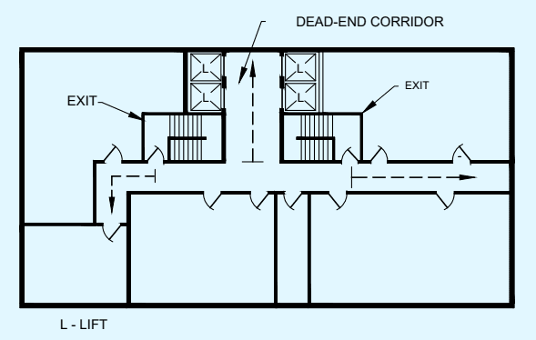
c) The dead-end corridor length in exit access should not exceed 6 m for educational, institutional and assembly occupancies. For other occupancies, the same should not exceed 15 m (see Fig. 9).
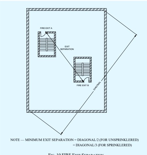
d) Fire exits should be placed as remote from each other as possible and should be arranged to provide direct access in separate directions from any point in the area served (see Fig. 10).
4.4.2Exits
4.4.2.1 Number of fire exits
The minimum required number of exits in a building should be determined based on occupant load (see Table 2) and width required per person (see Table 3) as appropriate to the type of exit for respective occupancies, subject to complying with maximum travel distance requirement (see Table 4).
4.4.2.3Capacities of means of egress
a) Exit capacity is the number of people that can pass through a stairway, and level components (door and corridor) and ramps. The total capacity of all the respective means of egress serving a floor should be sufficient to allow egress of the entire population of the floor.
b) The unit of exit width, used to measure the capacity of any exit, is 500 mm. A clear width of 250 mm needs to be counted as an additional half unit. Clear widths less than 250 mm need not be counted for exit width.
c) Width per person for stairways, and level components and ramps are to be determined using the capacity factors in accordance with Table 3.
For example, if an exit doorway measures 1 000 mm in clear width its capacity factor being 6.5, it would be defined as providing exit capacity for 1 000/6.5 occupants, that is, 153 persons (say 150 persons) and number of such exit doorways can then be calculated depending on the occupant load.
d) When calculating stairways, level components and ramps and other exit means, the capacity of the entire system should have to be based upon the minimum capacity available from any part of the system. The corridor, if so provided, should also to be planned with consideration of exit access adequacy for the number of occupants. Further, consider the situation of doors opening to an exit stairway. If the stairway provides an exit capacity of 150 persons, and the doors leading into the stairway provide an exit capacity of 153 persons, the overall exit system would be considered to provide the minimum exit capacity of only 150 persons afforded by the stairway. The exit planning will be limited by the most restrictive exit calculation under the means of egress.
e) In the procedures for determining required egress capacity, the number of required means of egress is based on a floor-by-floor consideration, rather than the accumulation of the occupant loads of all the floors. However, the number of means of egress cannot decrease as an occupant proceeds along the egress path.
FIG. 9 DEAD END CORRIDOR
4.4.2.4.3Staircases
4.4.2.4.3.1 General
The requirements of number of staircases should supplement the requirement of different occupancies in 6.1 to 6.9.
All high rises and special buildings, as mentioned in 1.2, should have a minimum of two staircases. The actual number of staircases should comply with the requirement of 4.4.2.1
NOTE — These required fire exit staircases calculated as per the laid down provisions, are recommended to be free of FAR.
All exit staircases should discharge, at the level of exit discharge, to the exit discharge, either,
a) directly, or
b) through an exit passageway, or
c) through a large lobby.
At least 50 percent of the staircases should discharge as per (a) and/or (b) above. For firefighting shafts, it is preferred to have the discharge through (a), or as an alternate through (b). Option (c) is not applicable for firefighting shafts. In case of residential buildings and educational buildings, firefighting shafts should discharge through (a) only.
Each compartment should be planned with its access to the firefighting shaft. In buildings/floors having three or more compartments, there should be at least two firefighting shafts to serve the compartments. In buildings/floors having three or more compartments, there should be at least two firefighting shafts to serve the compartments.
The minimum width of tread without nosing should be 250 mm for staircase of residential buildings. This should be minimum 300 mm for assembly, hotels, educational, institutional, business, and other buildings. The treads should be constructed and maintained in a manner to prevent slipping. The maximum height of riser should be 175 mm for staircase of one or two family dwelling residential buildings and 150 mm for other buildings. The number of risers in a flight is recommended as 12. However, considering the floor-to-floor height, there should not be more than 15 risers in a flight.
The staircases may be internal staircases or external staircases.
4.4.2.4.3.2 Internal staircases
The internal staircases may be constructed with an external wall, or otherwise, and should comply with the following:
a) Internal stairs should be constructed of non-combustible materials throughout, and should have fire resistant rating of minimum 120 min.
b) A staircase should not be arranged round a lift shaft.
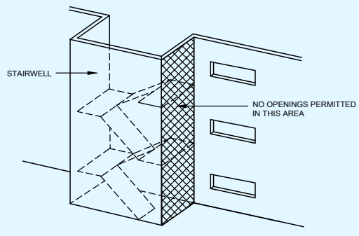
c) Fire exits should not be used as a portion of a supply, return or exhaust air system serving adjoining areas. Any opening(s) should not be permitted in walls or in doors, separating fire exits from adjoining areas.
4.4.2.5Smoke control of exits
a) In building design, compartmentation plays a vital part in limiting the spread of fire and smoke. The design should ensure avoidance of spread of smoke to adjacent spaces through the various leakage openings in the compartment enclosure, such as cracks, openings around pipes ducts, airflow grills and doors. In the absence of proper sealing of all these openings, smoke and toxic gases will obstruct the free movement of occupants of the building through the exits. Pressurization of staircases is of great importance for the exclusion of smoke and toxic gases from the protected exit.
b) Pressurization is a method adopted for protecting the exits from ingress of smoke, especially in high-rise buildings. In pressurization, air is injected into the staircases, lobbies, etc, as applicable, to raise their pressure slightly above the pressure in adjacent parts of the building. As a result, ingress of smoke or toxic gases into the exits will be prevented. The pressurization of staircases and lift lobbies should be adopted as given in Table 5.
The pressure difference for staircases should be 50 Pa.
Pressure differences for lobbies (or corridors) should be between 25 Pa and 30 Pa. Further, the pressure differential for enclosed staircase adjacent to such lobby (or corridors) should be 50 Pa. For enclosed staircases adjacent to non-pressurized lobby (or corridors), the pressure differential should be 50 Pa.
c) Equipment and ductwork for staircase pressurization should be in accordance with one of the following:
Directly connected to the stairway by ductwork enclosed in non-combustible construction.
If ducts used to pressurize the system are passed through shafts and grilles are provided at each level, it should be ensured that hot gases and smoke from the building cannot ingress into the staircases under any circumstances.
d) The normal air conditioning system and the pressurization system should be designed and interfaced to meet the requirements of emergency services. When the emergency pressurization is brought into action, the following changes in the normal air conditioning system should be effected:
Any re-circulation of air should be stopped and all exhaust air vented to atmosphere.
Any air supply to the spaces/areas other than exits should be stopped.
The exhaust system may be continued provided,
i) the positions of the extraction grills permit a general air flow away from the means of egress;
4.4.2.4Types of exit access and exits
Various types of exit access and exits are doorways, corridors and passageways, horizontal exits, internal staircases, exit passageways, external staircases, and ramps.
4.4.2.4.1 Doorways
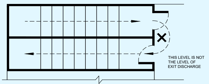
a) Every exit doorway should open into an enclosed stairway or a horizontal exit of a corridor or passageway providing continuous and protected means of egress (see Fig. 11 on unaccepted arrangement of doors in a stair).
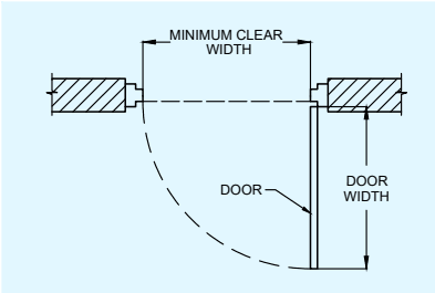
b) No exit doorway should be less than 1 000 mm in width. Door width in exits should also meet requirement of level components given in Table 3 except assembly buildings, where door width should be not less than 2 000 mm (see Fig. 12). Doorways should be not less than 2 000 mm in height.
c) Exit doorways should be operable from the side which they serve, without the use of a key.
d) Mirrors should not be placed on exit doors and in exits, to avoid confusion regarding the direction of exit.
e) Revolving doors can be accepted as a component in a means of egress where the following requirements are fully complied with:
Doors should be capable of collapsing to a book fold position with parallel egress paths, of width not less than 1 000 mm.
Doors should not be located within 3 m of the foot or top of stairs or escalators. A dispersal area should be provided between the stairs or escalators and the doors.
Each revolving door should be provided with a hinged door in the same wall within 3 m thereof, with same exiting capacity.
Each revolving door should be considered as capable of exiting only 50 persons.
f) All fire rated doors and assembly should be provided with certificate and labels prominently indicating
the manufacturer's identification, door details covering door type, serial/batch number, month and year of manufacture, fire resistance rating, etc. The doors and assembly should be certified with all prescribed hardware such as hinges, locks, panic bars, door closers, and door viewers.
g) Access controlled doors — Access controlled doors and electromagnetic doors should fall under this category. These should meet the following requirements:
Doors should have fire rating as per the requirements at the location of installation;
Activation of the building automatic sprinkler or fire detection system, if provided, should automatically unlock the doors in the direction of egress, and the doors should remain unlocked until the automatic sprinkler system or fire-alarm system has been manually reset;
4.5Compartmentation
4.5.1 General
It is important to limit the spread of a fire in special/high rise buildings, usually through the use fire barriers. In some instances, these barriers need to be penetrated for ductwork, plumbing and electrical systems, and in such cases, use of passive fire protection measures should be done so that the integrity of these barriers is not compromised.
4.5.2 The compartmentation can be achieved with following type of construction/type of fire barrier with protected openings:
a) Type A — Masonry construction with fire rated door assembly;
b) Type B — Fire rated fabric dropdown curtain assembly;
c) Type C — Fire rated glazed partition and door assembly;
d) Type D — Fire rated gypsum board/cementitious board assembly; and
e) Type E — Masonry construction with fire rated metal sliding door.
Integrity (E) is the ability of the fire curtain assembly when exposed to fire from one side to withstand temperature up to 1 050 °C, to resist passage of flames and hot gases for a period of 120 min.
Radiation control (EW) is the ability of the fire curtain assembly when exposed to fire from one side to resist transfer of heat on the other side. When measured, it should does not exceed 15 kW/m2at 1 m distance.
Insulation (EI) is the ability of the fire curtain assembly when exposed to fire from one side to limit temperature rise on the other not exceeding 140 °C above the ambient.
Smoke control (Sa) is the ability of fire curtain assembly when exposed to a fire from one side resist passage of hot/cold smoke not exceeding 3 m³/m/h at a pressure of smoke leakage rate of 25 Pa.
4.5.2.1 Type B — Fire rated fabric dropdown curtain assembly
The fire rated fabric should be tested and certified by any reputed third-party independent certification body for following parameters:
a) Type 1 — Integrity (E) of 120 min + Radiation (EW) of 60 min + Smoke control (Sa);
b) Type 2 — Integrity (E) of 120 min + Radiation (EW) of 120 min + Smoke control (Sa); and
c) Type 3 — Integrity + Radiation (EW) of 120 min + Insulation (EI) of 60 min + Smoke control (Sa).
4.5.2.2 Type C — Fire rated glazed partition and door assembly
The fire rated glazed partition and door assembly should be tested and certified by any reputed third-party independent certification body for following parameters:
4.6Smoke Control
4.6.1 Smoke Exhaust and Pressurization of Areas Above Ground
Corridors in exit access (exit access corridor) are created for meeting the requirement of use, privacy, and layout
in various occupancies. These are most often noted in hospitality, health care occupancies and sleeping accommodations.
Exit access corridors of guest rooms and indoor patient department/areas having patients lacking self-preservation and for sleeping accommodations such as service apartments, custodial, penal, and mental institutions, etc, should be provided with 60 min fire resistant wall and 30 min self-closing fire doors along with all fire stop sealing of penetrations.
Smoke exhaust system having make-up air and exhaust air system or alternatively pressurization system with supply air system for these exit access corridors should be required.
Smoke exhaust system having make-up air and exhaust air system should also be required for theatres/auditoria.
Such smoke exhaust system should also be required for large lobbies and which have exit through staircase leading to exit discharge. This would enable eased exit of people through smoke-controlled area to exit discharge.
All exit passageway (from exit-to-exit discharge) should be pressurized or naturally ventilated. The mechanical pressurization system should be automatic in action with manual controls in addition. All such exit passageway should be maintained with integrity for safe means of egress and evacuation. Doors provided in such exit passageway should be fire rated doors of 120 min rating.
Smoke exhaust system where provided, for above areas and occupancies should have a minimum of 12 air changes per hour smoke exhaust mechanism.
Pressurization system where provided, should have a minimum pressure differential of 25-30 Pa in relationship to other areas.
The smoke exhaust fans in the mechanical ventilation system should be fire rated, that is, 250 °C for 120 min.
For naturally cross-ventilated corridors or corridors with operable windows, such smoke exhaust system or pressurization system will not be required.
4.6.2 Smoke Exhaust and Pressurization of Areas Below Ground
a) Each basement should be separately ventilated;
b) Vents with cross-sectional area (aggregate) not less than 2.5 percent of the floor area spread evenly round the perimeter of the basement should be provided in the form of grilles, or breakable stall board lights or pavement lights or by way of shafts.
4.7Gas Supply
4.7.1 Town Gas/LPG Supply Pipes
Where gas pipes are run in buildings, the same should be run in separate shafts exclusively for this purpose and these should be on external walls, away from the staircases. Gas distribution pipes should always be below the false ceiling. The length of these pipes should be as short as possible. In the case of kitchen cooking range area, hood should have grease filters using metallic grille to trap oil vapours escaping into the fume hood.
NOTE — For detailed information on gas pipe installations, reference may be made to Part E ‘Plumbing services, Section 4 Gas supply of this NBCS.
4.7.2 Thermal Detectors
These should be installed into fume hoods of large kitchens for hotels, hospitals, and similar areas located in high rise buildings. Arrangements should be made for automatic tripping of the exhaust fan in case of fire. If gas is used, the same should be shut off. The voltage should be 24 V or 100 V d.c. operated with external rectifier. The valve should be of the hand re-set type and should be located in an area segregated from cooking ranges. Valves should be easily accessible. The hood should have manual facility for steam or suitable hood extinguishing gas released depending on duty condition.
4.7.3 Gas cylinders and manifold should need to be housed in a detached location with no other occupancy within distances prescribed in good practice [F(14)] thereof. There should be an enclosure suitably ventilated. It is desirable to provide medium velocity spray nozzles which can be operated by quick opening valve situated away
from the enclosure.
4.7.4 In the case of gas cylinders, if manifold has to be installed on podium/close to podium, the same should be away from any air intakes/smoke exhaust openings/any windows.
4.7.5 Pressure regulating stations should be designed and installed at critical locations for excess flow shut off valves. Seismic shut off valve at the main distribution point should be installed for buildings having mixed use assembly occupancy (like malls) and institutional occupancy above 15 m.
4.7.6 Gas meters should be housed in a suitably constructed metal cupboard located in a well-ventilated space, keeping in view the fact that LPG is heavier than air and natural gas is lighter than air.
4.7.7 Wherever LPG reticulation/cylinders are used in buildings above 100 m, gas leak detectors should be provided at the usage points and monitored from fire command centre. The cables used for signalling should be circuit integrity cables.
Rooms containing high pressure boilers, refrigerating machinery, transformers, or other service equipment subject to possible explosion should not be located directly under or adjacent to fire exits. All such rooms should be effectively cut-off from other parts of the building and should be provided with adequate vents to the outside air.
All rooms or areas of high hazard in additions to those hereinbefore mentioned, should be segregated, or should be protected with fire resistant walls having fire rating of 120 min as fire, explosion or smoke therefrom is likely to interfere with safe egress from the building. Further,
a) each building should be provided with an approved outside gas shut-off valve conspicuously marked. The detailed requirements regarding safe use of gas should be as specified in Part E ‘Plumbing services, Section 4 Gas Supply’ of this NBCS; and
b) all exterior openings in a boiler room or rooms that contain central heating equipment, if located below opening in another storey or if less than 3 m from other doors or windows of the same building should be protected by a fire assembly as in 3.5.4. Such assemblies should be fixed, automatic or self-closing.
Notes 86
1 If the building has any type of combustible storage, combustible packing, fuel storage, boilers, furnaces such areas should be protected and should comply to protection level CL-6.
2 Alternate suppression agent should be considered as per relevant Indian Standards if water is not a suitable agent for materials protected.
3 Oxidizing materials, ignitable liquids, water resistive chemicals, explosives, aluminium dust, or any other explosive environment should be treated separately.
4 Protection should comply to supplementary protection for specific hazard/critical rooms as per Table 9/ Table 10/ Table 11 as applicable.
5 Pump pressure and quantity should be supported by hydraulic calculations.
6 If the cluster of buildings exceeds 5, another set of pumps and water storage of similar capacity should be provided. A maximum of two such sets is recommended, provided it satisfies the hydraulic requirements and functioning at the remotest point.
7 Table 7K and Table 7M suggesting the basis for water quantity required for fire-fighting, respectively for combined (sprinkler and hose) protection and hose protection be considered.
Table 7H Requirements for Firefighting Installations – For Storage Buildings[ Clauses 4.9 (a), 4.9 (c), 4.9(e), 5.1.1 (a), 5.1.1(d), 5.1.2.1, 5.1.3 (a), D-6.1, G-2(f) and Table 31 ]
Sl No.
Type of Building Occupancy
Type of Installation
Fire Extinguisher
First Aid Hose Reel
Down Comer
Wet Riser
Yard Hydrant
Automatic Wet Sprinkler System
Automatic Detection and Alarm System
Public Address and Voice Evacuation System
(1)
(2)
(3)
(4)
(5)
(6)
(7)
(8)
(9)
(10)
Storage Buildings (H) (See Note 1, 2 and 3)
i)
Built-up area up to 500 m² (HL-4)
R
R
NR
R
NR
NR
R
NR
ii)
501 m² to 1 000 m² (HL-5)
R
R
NR
R
R
NR
R
NR
Free Standard provided by BIS via BSB Edge Private Limited to Datta Kare - Margao() 36.255.235.24.
e) Gymnasium, sports room, library and alike with equipment, stacks and the like.
4.6
-
This includes performance stages, indoor badminton court, squash court with
Table 2 (Continued)
Table 2 (Continued)
Table 2 (Continued)
Table 2 (Continued)
Sl No.
Building Occupancy
Net Occupant Load Factor(m2/person)(see Note 7)
Gross Occupant Load Factor(m2/person)(see Note 1)
(1)
(2)
(3)
(4)
limited number of performers and player (while audience for the same if any should be under (c) as above).
f) Swimming pool
1) Water surface
3.5
-
2) Deck
2.0
-
g) Mall - Basement with sales floor
2.1
-
h) Mall - Street floor
2.1
-
j) Mall - Upper sales floor
4.3
-
k) Mall - Food court
-
1.8
m) Mall - Theatre screens
-
see Note 4
n) Storage/warehouse, receiving and the like
14.3
-
v)
Group F: Mercantile
a) Street floor and above
-
2.1
b) Below street floor
-
3.0
vi)
Group E: Business
7.1
-
vii)
Group E: For Datacentres
-
20.0
a) Admin areas
-
10.0
b) Data hall, server room, equipment room areas
-
50.0
see Annex G
see Annex G
viii)
Group G: Industrial
-
a) Low hazard
-
20.0
b) Moderate hazard
-
15.0
c) High hazard
-
10.0
ix)
Group H: Storage (see Note 5)
-
30.0
x)
Group J: Hazardous
-
10.0
NOTES
NOTES
NOTES
NOTES
1 Gross area is the floor area as defined in 2.35.
1 Gross area is the floor area as defined in 2.35.
1 Gross area is the floor area as defined in 2.35.
1 Gross area is the floor area as defined in 2.35.
2 Occupant load factor in dormitory portions of homes for the aged, orphanages, insane asylums, etc, where sleeping
2 Occupant load factor in dormitory portions of homes for the aged, orphanages, insane asylums, etc, where sleeping
2 Occupant load factor in dormitory portions of homes for the aged, orphanages, insane asylums, etc, where sleeping
2 Occupant load factor in dormitory portions of homes for the aged, orphanages, insane asylums, etc, where sleeping
Table 2 (Concluded)
Table 2 (Concluded)
Table 2 (Concluded)
Table 2 (Concluded)
SI No.
Building Occupancy
Net Occupant Load Factor (m²/person) (see Note 7)
Gross Occupant Load Factor (m²/person) (see Note 1)
(1)
(2)
(3)
(4)
accommodation is provided, should be calculated at not less than 7.5 m² gross floor area/person.3 Commercial kitchen in the above occupancies should be calculated at 9.3 m² net floor area/person.4 In case of assembly occupancy having fixed seats, the occupant load should be determined by multiplying the number of seats by 1.2.5 Car parking areas under occupancy other than storage should also be 30 m² per person.6 Usable carpet area is the total of all corridors, passages, enclosed offices/rooms excluding rack and UPS/battery foot print7 Net area is not the carpet area. See 2.36.* Gross area is highly recommended to be used than the net area, to avoid double counting. Net area is possible to be indicated for spaces having concentration of people is typical in certain occupancies; and other common spaces/areas in a floor plate may be used by the same set of occupants. Moreover, gross area provides a safer, more conservative occupant load for the entire floor, ensuring exits are sized for the maximum possible capacity. Further, net area is used for specific rooms (like classrooms or assembly halls) where the furniture and layout are predictable, but using it for an entire floor plate often underestimates the total population because it excludes corridors, closets, and wall thicknesses where people still circulate.
accommodation is provided, should be calculated at not less than 7.5 m² gross floor area/person.3 Commercial kitchen in the above occupancies should be calculated at 9.3 m² net floor area/person.4 In case of assembly occupancy having fixed seats, the occupant load should be determined by multiplying the number of seats by 1.2.5 Car parking areas under occupancy other than storage should also be 30 m² per person.6 Usable carpet area is the total of all corridors, passages, enclosed offices/rooms excluding rack and UPS/battery foot print7 Net area is not the carpet area. See 2.36.* Gross area is highly recommended to be used than the net area, to avoid double counting. Net area is possible to be indicated for spaces having concentration of people is typical in certain occupancies; and other common spaces/areas in a floor plate may be used by the same set of occupants. Moreover, gross area provides a safer, more conservative occupant load for the entire floor, ensuring exits are sized for the maximum possible capacity. Further, net area is used for specific rooms (like classrooms or assembly halls) where the furniture and layout are predictable, but using it for an entire floor plate often underestimates the total population because it excludes corridors, closets, and wall thicknesses where people still circulate.
accommodation is provided, should be calculated at not less than 7.5 m² gross floor area/person.3 Commercial kitchen in the above occupancies should be calculated at 9.3 m² net floor area/person.4 In case of assembly occupancy having fixed seats, the occupant load should be determined by multiplying the number of seats by 1.2.5 Car parking areas under occupancy other than storage should also be 30 m² per person.6 Usable carpet area is the total of all corridors, passages, enclosed offices/rooms excluding rack and UPS/battery foot print7 Net area is not the carpet area. See 2.36.* Gross area is highly recommended to be used than the net area, to avoid double counting. Net area is possible to be indicated for spaces having concentration of people is typical in certain occupancies; and other common spaces/areas in a floor plate may be used by the same set of occupants. Moreover, gross area provides a safer, more conservative occupant load for the entire floor, ensuring exits are sized for the maximum possible capacity. Further, net area is used for specific rooms (like classrooms or assembly halls) where the furniture and layout are predictable, but using it for an entire floor plate often underestimates the total population because it excludes corridors, closets, and wall thicknesses where people still circulate.
accommodation is provided, should be calculated at not less than 7.5 m² gross floor area/person.3 Commercial kitchen in the above occupancies should be calculated at 9.3 m² net floor area/person.4 In case of assembly occupancy having fixed seats, the occupant load should be determined by multiplying the number of seats by 1.2.5 Car parking areas under occupancy other than storage should also be 30 m² per person.6 Usable carpet area is the total of all corridors, passages, enclosed offices/rooms excluding rack and UPS/battery foot print7 Net area is not the carpet area. See 2.36.* Gross area is highly recommended to be used than the net area, to avoid double counting. Net area is possible to be indicated for spaces having concentration of people is typical in certain occupancies; and other common spaces/areas in a floor plate may be used by the same set of occupants. Moreover, gross area provides a safer, more conservative occupant load for the entire floor, ensuring exits are sized for the maximum possible capacity. Further, net area is used for specific rooms (like classrooms or assembly halls) where the furniture and layout are predictable, but using it for an entire floor plate often underestimates the total population because it excludes corridors, closets, and wall thicknesses where people still circulate.
FIG. 10 FIRE EXIT SEPARATION
Table 3 Capacity Factors
[Clauses 4.4.2.1, 4.4.2.3(c), 4.4.2.4.1(b), 4.4.2.4.2(a) and 4.4.2.4.3.5(a)]
Sl No.
Occupancy Group
Width per Person mm
Stairways
Level Components and Ramps
(1)
(2)
(3)
(4)
i)
Residential (Group A)
10
6.5
ii)
Educational (Group B)
iii)
Institutional (Group C)
15
13
iv)
Assembly (Group D)
10
6.5
v)
Business (Group E)
vi)
Mercantile (Group F)
vii)
Industrial (Group G)
viii)
Storage (Group H)
ix)
Hazardous (Group J)
18
10
d) No flue chimney, electromechanical equipment, air conditioning units, gas piping or electrical panels should be allowed in the stairway.
e) Notwithstanding the detailed provision for exits in accordance with 4.2 and 4.3, the following minimum width should be provided for staircases for respective building typology:
Residential building (One or two family dwellings) 1.00 m NOTE — For row housing with 2 storeys, the minimum width should be 0.75 m.
Residential building (A-I, A-II and A-III) 1.25 m
Residential hotel building (A-IV and A-V) 1.50 m
Assembly building 2.00 m
Educational building 1.50 m
Institutional building 2.00 m
All other buildings 1.50 m
NOTE — Where staircase width is above 2.00 m, it is recommended to provide a central handrail.
f) A handrail should be provided on one side of the staircase of width less than 1 500 mm, and on both sides of the staircase of width 1 500 mm and more. The projection of handrail(s) in the staircase width should not be more than 90 mm.
g) Handrails may project inside the measured width by not more than 90 mm.
h) The design of staircase should also take into account the following:
The minimum headroom in a passage under the landing of a staircase and under the staircase should be 2.2 m.
Access to fire sexit staircase should be through a fire door of a minimum 120 min fire resistance rating.
No living space, store or other fire risk should open directly into staircases.
The exit (including staircases) should be continuous from refuge floors or terrace level, as applicable, to the level of exit discharge.
No electrical shafts/air conditioning ducts or gas pipes, etc, should pass through or open in the staircases.
Lifts should not open in staircase (or in mid-landings).
No combustible material should be used for decoration/wall panelling in the staircase.
Beams/columns and other building features should not reduce the head room/width of the staircase.
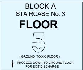
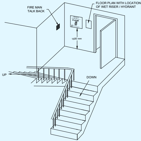
The floor indication board, indicating the location/designated number of staircase, respective floor number and direction to exit discharge should be placed inside the staircase, on the wall nearest to the fire door. It should be of size not less than 300 mm × 200 mm (see Fig. 13).
Individual floors should be prominently indicated on the wall outside the staircase and facing it.
All staircase should terminate at the level of exit discharge. The access to the basement should be by a separate staircase.
Scissors type staircases (of type where intermingling of persons in the landing is possible or of type where both stairs use the common air space) should not be treated as part of exit.
4.4.2.4.3.3 Curved stairs
Curved stairs should not be treated as part means of egress. However, these may be used as part of exit access provided the depth of tread is not less than 280 mm at a point 350 mm from the narrower end of the tread and the smallest radius is not less than twice the stair width.
4.4.2.4.3.4 External staircases
The external staircases are the staircases provided on the external wall/facade, and should comply with the following:
a) External stairs should always be kept in sound and usable condition;
b) All external stairs should be directly connected to the ground;
c) Entrance to the external stairs should be separate and remote from the internal staircase;
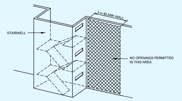
d) Where an external staircase is provided, it should be ensured that the use of it at the time of fire is not prejudiced by smoke and flame from openings (for example, windows, doors) in the external face of the building. Care should be taken to ensure that no external wall or window opening opens on to or close to an external stair. If such openings exists within 3 m from an external staircase, they should be protected with fire rated doors/window assemblies with rating of at least 60 min (see Fig. 14);
e) The external stairs should be constructed of non-combustible materials, and any doorway leading to it should have minimum 120 min fire resistance;
f) No external staircase, should be inclined at an angle greater than 45° from the horizontal;
g) External stairs should have straight flight not less than 1 500 mm wide;
h) Handrails, to be provided on both sides, should be of a height not less than 1 000 mm and not exceeding 1 200 mm. There should be provisions of balusters with maximum gap of 150 mm; and
j) The use of spiral staircase should be limited to low occupant load and to a building not exceeding 9 m in height. A spiral staircase should be not less than 1 500 mm in diameter and should be designed to give adequate headroom.
4.4.2.4.3.5 Ramps
a) Ramps should comply with all the applicable requirements for staircases regarding enclosure, capacity (see also Table 3) and limiting dimensions, except where specified in 6.1 to 6.9 for special uses and occupancies;
b) The slope of a ramp should not exceed 1 in 12 (8 percent);
c) Ramp(s) should be surfaced with approved slip resistant materials that are securely attached. No perforations are permissible on ramp floors;
d) Any changes in travel direction in ramp should be preceded by landings of minimum 1.5 m × 1.5 m size;
e) Ramps and intermediate landings should continue with no decrease in width along the direction of egress travel;
f) Outside ramps and landings should be designed to minimize water accumulation on their surfaces;
g) Ramps should have landings located at the top, at the bottom, and at doors opening onto the ramp;
h) Every landing should be not less than 1 500 mm long in the direction of travel;
j) Where the ramp is not part of an accessible route, the ramp landings should not be required to exceed 1 250 mm in the direction of travel, provided that the ramp has a straight run; and
k) Handrails should be provided on all ramps on both sides (see 4.4.2.4.3.4)
NOTE — Above requirements are not applicable to basement car parking ramps.
The ramps should, in addition, comply with the requirements given in good practice [F(31)].
BLOCK A STAIRCASE No. 3 FLOOR
( GROUND TO XX FLOOR )
PROCEED DOWN TO GROUND FLOOR FOR EXIT DISCHARGE
9A EXAMPLE OF A STAIRWAY MARKING SIGN (FLOOR INDICATION BOARD)
9B STAIR SIGN PLACEMENT
NOTE — BLOCK/WING/BUILDING NAME TO BE PROJECT SPECIFIC. STAIRCASE No.
SHOWN AS "3" IS INTENDING TO SHOW THE NUMBER ASSIGNED TO THE STAIRCASE. ALL EXITS PREFERABLY TO BE ASSIGNED WITH NUMBER /IDENTIFICATION ENABLING OCCUPANT/FIRE MAN TO DECLARE LOCATION / POSITION.
FIG. 13 SIGN MARKING AND REQUIREMENT IN EXIT
14A LIMITATIONS ON OPENINGS NEAR STAIRWELL
FIG. 14 OPENING RESTRICTIONS
14B OPENING RESTRICTIONS ON STAIRWELL WALLS
ii) the construction of the ductwork and fans is such that, it will not be rendered inoperable by hot gases and smoke; and
iii) there is no danger of spread of smoke to other floors by the path of the extraction system which can be ensured by keeping the extraction fans running.
e) For pressurized stair enclosure systems, the activation of the systems should be initiated by signalling from fire alarm panel.
f) Pressurization system should be integrated and supervised with the automatic/manual fire alarm system for actuation.
g) Wherever pressurized staircase is to be connected to unpressurized area, the two areas should be segregated by 120 min fire resistant wall.
h) Fresh air intake for pressurization should be away (at least 4 m) from any of the exhaust outlets/grille.
Table 5 Pressurization of Staircases and Lift Lobbies[Clauses 4.4.2.5 (b) and D-2]
Sl No.
Component
Height of the Building
Less than 15 m
15 m to 30 m
More than 30 m
(1)
(2)
(3)
(4)
(5)
i)
Internal staircase not with external wall
Pressurized except for residential buildings (apartment houses and one or two family dwellings)
Pressurized
Pressurized
ii)
Internal staircase with external wall
Pressurized except for residential buildings (Apartment houses and one or two family dwellings) or Naturally ventilated
Naturally ventilated or Pressurized
Cross-ventilated or Pressurized
iii)
Lift lobby
Not required at ground and above. However, lift lobby segregation and pressurization is required for lift commuting from ground to basement
Naturally ventilated or Pressurized1)
Cross-ventilated or Pressurized1)
NOTES
1 The natural ventilation requirement of the staircase should be achieved through opening at each landing, of an area 0.5 m2to 1.5 m2(as defined earlier) in the external wall. A cross ventilated staircase should have 2 such openings in opposite/adjacent walls or the same should be cross-ventilated through the corridor.
2 Enclosed staircase leading to more than one basement should be pressurized.
Lift lobby with fire doors (120 min) at all levels with pressurization of 25 Pa to 30 Pa is required. However, if lift lobby cannot be provided at any of the levels in air-conditioned buildings or in internal spaces where funnel/flue effect may be created, lift hoistway should be pressurized at 50 Pa. For building greater than 30 m, multiple point injection air inlets to maintain desired pressurization level should be provided. If the lift lobby, lift, and staircase are part of firefighting shaft, lift lobby necessarily has to be pressurized in such case, unless naturally ventilated.
Loss of power to the part of the access control system that locks the doors should automatically unlock the doors in the direction of egress;
A manual release device should be provided in the readily accessible vicinity of the egress door with a signage 'PUSH TO EXIT' and when the same is operated, it should result in direct interruption of power to the lock, independent of the access control system electronics.
h) Turnstiles — Turnstiles or similar devices that restrict travel to one direction or are used to collect fares or admission charges should not be placed so as to obstruct any required means of egress unless door openings of required width are available within 3 m thereof.
Turnstiles or such similar devices should also be disengaged through automatic or manual intervention to allow egress in the direction of exit.
j) Doors in folding partition should not be treated as approved means of egress.
Table 4Travel Distance (Based on Occupancy and Construction Type) [Clauses 4.4.2.1, 4.4.2.2 (a), 4.4.2.4.2 (a) and 6.8.1.1]
[Clauses 4.4.2.1, 4.4.2.2 (a), 4.4.2.4.2 (a) and 6.8.1.1]
[Clauses 4.4.2.1, 4.4.2.2 (a), 4.4.2.4.2 (a) and 6.8.1.1]
[Clauses 4.4.2.1, 4.4.2.2 (a), 4.4.2.4.2 (a) and 6.8.1.1]
[Clauses 4.4.2.1, 4.4.2.2 (a), 4.4.2.4.2 (a) and 6.8.1.1]
[Clauses 4.4.2.1, 4.4.2.2 (a), 4.4.2.4.2 (a) and 6.8.1.1]
Sl No.
Occupancy Group
Maximum Travel Distance m
Maximum Travel Distance m
Maximum Travel Distance m
Sl No.
Occupancy Group
Types 1 and 2 (Unsprinklered)
Types 1 and 2 (Sprinklered)
Types 3 and 4
(1)
(2)
(3)
(4)
(5)
i)
Residential (Group A)
30.00
60.00
22.5
ii)
Educational (Group B)
30.00
45.00
22.5
iii)
Institutional (Group C)
30.00
45.00
22.5
iv)
Assembly (Group D)
30.00
45.00
30.00
v)
Business (Group E)
Businesses (including admin area of Datacentre building)
30.00
60.00
30.00
Datacentre building
N.A.
60.00
N.A.
vi)
Mercantile (Group F)
30.00
45.00
30.00
Sl No.
Occupancy Group
Maximum Travel Distance m
Maximum Travel Distance m
Maximum Travel Distance m
Sl No.
Occupancy Group
Types 1 and 2 (Unsprinklered)
Types 1 and 2 (Sprinklered)
Types 3 and 4
(1)
(2)
(3)
(4)
(5)
vii)
Industrial (Group G)
Industrial (Group G)
Industrial (Group G)
Industrial (Group G)
vii)
G-1, G-2
45.00
60.00
see Note 3
vii)
G-3
22.50
45.00
see Note 3
viii)
Storage (Group H)
30.00
90.00
see Note 3
ix)
Hazardous (Group J)
22.50
30.00
see Note 3
NOTES 1The common path of travel should be not more than 50 percent of the above distances. 2Ramps are not to be counted as an exit in case of basements below the first basement in car parking. 3Construction of Type 3 or Type 4 is not permitted. 4Utility service areas and equipment areas may be exempt from the measurement of travel distance from within the room. 5 For ceiling height 10 m or above at ground floor in buildings such as airports, exhibition halls, convention centres, atrium in shopping malls, entrance lobbies and the like and provided with sprinkler system, the travel distance in such areas may be increased by 100 percent of the values specified. This is not to be applied to the values given in col (4) above. 6 In such buildings having ceiling heights 17 m or more and would have sprinkler exemption, the travel distance of such areas may be allowed to be increased by 100 percent of the values specified. This is not to be applied to the values given in col (4) above. In such cases, to prevent heat build-up at ceiling level, suitable smoke/heat venting systems are recommended.
NOTES 1The common path of travel should be not more than 50 percent of the above distances. 2Ramps are not to be counted as an exit in case of basements below the first basement in car parking. 3Construction of Type 3 or Type 4 is not permitted. 4Utility service areas and equipment areas may be exempt from the measurement of travel distance from within the room. 5 For ceiling height 10 m or above at ground floor in buildings such as airports, exhibition halls, convention centres, atrium in shopping malls, entrance lobbies and the like and provided with sprinkler system, the travel distance in such areas may be increased by 100 percent of the values specified. This is not to be applied to the values given in col (4) above. 6 In such buildings having ceiling heights 17 m or more and would have sprinkler exemption, the travel distance of such areas may be allowed to be increased by 100 percent of the values specified. This is not to be applied to the values given in col (4) above. In such cases, to prevent heat build-up at ceiling level, suitable smoke/heat venting systems are recommended.
NOTES 1The common path of travel should be not more than 50 percent of the above distances. 2Ramps are not to be counted as an exit in case of basements below the first basement in car parking. 3Construction of Type 3 or Type 4 is not permitted. 4Utility service areas and equipment areas may be exempt from the measurement of travel distance from within the room. 5 For ceiling height 10 m or above at ground floor in buildings such as airports, exhibition halls, convention centres, atrium in shopping malls, entrance lobbies and the like and provided with sprinkler system, the travel distance in such areas may be increased by 100 percent of the values specified. This is not to be applied to the values given in col (4) above. 6 In such buildings having ceiling heights 17 m or more and would have sprinkler exemption, the travel distance of such areas may be allowed to be increased by 100 percent of the values specified. This is not to be applied to the values given in col (4) above. In such cases, to prevent heat build-up at ceiling level, suitable smoke/heat venting systems are recommended.
FIG. 11 UNACCEPTABLE ARRANGEMENT FOR ENCLOSING A STAIR SERVING AS A REQUIRED EXIT
FIG. 12 MINIMUM CLEAR DOOR WIDTH
4.4.2.4.2 Corridors and passageways of means of egress
a) Corridors and passageways should be of width not less than the calculated aggregate width of exit doorways leading from them in the direction of travel to the exit (see Table 3 and Table 4); and
b) In the case of buildings where there is a central corridor, which is part of exit access, the doors of rooms (except for rooms having assembly occupancy) should open inwards to permit smooth flow of traffic in the corridor.
a) Type 1 — Integrity (E) of 120 min + Radiation (EW) of 120 min + Insulation (EI) of 30 min + Smoke control (Sa); and
b) Type 2 — Integrity (E) of 120 min + Radiation (EW) of 120 min + Insulation (EI) of 60 min + Smoke control (Sa)
4.5.3 Floor(s) should be compartmented with area as given in Table 6. The maximum size of the compartment is suggested as follows. However, State/Local Authorities may prescribe their own requirements based on their risk assessment and other fire safety provisions.
Table 6 Compartmentation(Clause 4.5.3)
Table 6 Compartmentation(Clause 4.5.3)
Table 6 Compartmentation(Clause 4.5.3)
Table 6 Compartmentation(Clause 4.5.3)
Table 6 Compartmentation(Clause 4.5.3)
Sl No.
Type of Building
Floor Area Compartmentation Area (without Sprinkler) m²
Floor Area Compartmentation (when Sprinklered) m²
Type of Construction/Type of Fire Barrier with Protected Openings
(1)
(2)
(3)
(4)
(5)
i)
Enclosed basement vehicle parking in residential, educational, institutional, assembly, business, mercantile, industrial or storage occupancies
750
5 000
E - Barrier between the designated fire compartments/zonesB - Limited to driveway not exceeding 9 m with Type-2 only.
Table 6 (Continued)
Table 6 (Continued)
Table 6 (Continued)
Table 6 (Continued)
Table 6 (Continued)
Sl No.
Type of Building
Floor Area Compartmentation Area (without Sprinkler) m²
Floor Area Compartmentation (when Sprinklered) m²
Type of Construction/Type of Fire Barrier with Protected Openings
(1)
(2)
(3)
(4)
(5)
ii)
Basements other than car parking in residential, educational, institutional, assembly, business, mercantile, industrial and storage occupancies
750
2 000
A/D - barrier between the designated fire compartments/zones
iii)
Hospitals and nursing homes with beds/sleeping patients in institutional occupancies
750
2 000
Any combination of A, B (Type-3 only), D - barrier between the designated fire compartments/zones
iv)
Buildings used for custody and care of children, convalescents, aged people who are incapable of self-preservation
750
1 500
Any combination of A, B (Type-3 only), D - barrier between the designated fire compartments/zones
Any combination of A, B (Type 2 only), D - barrier between the designated fire compartments/zones
vi)
Assembly buildings with/without atriums
1 500
Not essential
Any combination of A, B (Type 2 only), D - barrier between the designated fire compartments/zones
vii)
Buildings under business occupancy
750
3 000
Any combination of A, B, C (Type 1), D - barrier between the designated fire compartments/zones
viii)
Datacentre buildings
See Note 1
2 000
Any combination of A, C (Type 2), D - barrier between the designated fire compartments/zones
ix)
Hotel building with or without dining facilities
750
3 000
Any combination of A, C (Type 1), D - barrier between the designated fire compartments/zones
x)
Industrial buildings less than 6.7 m in height
1 500
10 000
Any combination of A, E - barrier between the designated fire compartments/zones
Table 6 (Concluded)
Table 6 (Concluded)
Table 6 (Concluded)
Table 6 (Concluded)
Table 6 (Concluded)
Sl No.
Type of Building
Floor Area Compartmentation Area (without Sprinkler) m²
Floor Area Compartmentation (when Sprinklered) m²
Type of Construction/ Type of Fire Barrier with Protected Openings
(1)
(2)
(3)
(4)
(5)
xi)
Hazardous or high hazard buildings
See Note 1
500
A-barrier between the designated fire compartments/zones
xii)
Buildings with atrium with smoke management system
See Note 1
Not required
Subject to compliance of atrium as in Annex E
xiii)
Warehouses less than 5.0 m in height
See Note 1
5 000
See also good practice [F(142)]
NOTES
NOTES
NOTES
NOTES
NOTES
1 Compartmentation size is not specified, as the buildings have to be sprinklered.
1 Compartmentation size is not specified, as the buildings have to be sprinklered.
1 Compartmentation size is not specified, as the buildings have to be sprinklered.
1 Compartmentation size is not specified, as the buildings have to be sprinklered.
1 Compartmentation size is not specified, as the buildings have to be sprinklered.
2 Ceiling level partition may be considered (from ceiling level to 25 percent of floor height) to act as a smoke reservoir and venting thereof.
2 Ceiling level partition may be considered (from ceiling level to 25 percent of floor height) to act as a smoke reservoir and venting thereof.
2 Ceiling level partition may be considered (from ceiling level to 25 percent of floor height) to act as a smoke reservoir and venting thereof.
2 Ceiling level partition may be considered (from ceiling level to 25 percent of floor height) to act as a smoke reservoir and venting thereof.
2 Ceiling level partition may be considered (from ceiling level to 25 percent of floor height) to act as a smoke reservoir and venting thereof.
4.5.3.1 For space with large heights [such as airports, exhibition halls, convention centres, atrium in shoppingmalls, warehouses (of height beyond 5 m), industrial (of height beyond 6.7 m), double height entrance lobbies and the like], these may be exempted from above requirement of compartmentation.
4.5.3.2 In addition to the above floor area compartmentation, all critical utility rooms within each compartment area construction should be 2 h fire rated. Rooms such as electrical room, server room, uninterrupted power supply (UPS) room, battery room, lift machine rooms, IT networking room, main distribution frame (MDF), intermediate distribution frame (HUB/IDF rooms), main communication room (MCR room), network switch rooms, multiplexer (MUX) rooms, telecom equipment room, janitor storage room, chemical storage room, QA and QC laboratories, etc, should be enclosed from all sides and construction should be 2 h fire rated irrespective of the size/area.
4.5.3.3 Guest rooms, guest room corridors, banquets, should be 60 m fire compartmented with 30 min fire rated doors, in addition to above area of compartmentation.
4.5.3.4 In buildings with open atrium, the effect of compartmentation on the atrium should be disregarded, provided the fire safety requirements given in Annex E on atrium are complied.
4.5.3.5 In industrial and storage occupancies, all hazardous areas irrespective of area/size should be compartmented namely, vehicle charging areas, ignitable chemical storage areas, hazardous waste storage areas, flammable scrap storage areas, unless these are located 30 m away from any adjacent occupied buildings.
4.5.3.6 All live cooking areas with any type of fuel (induction, LPG, PNG, etc) in hotels, IT parks, business buildings cafeteria, hostels, educational facility, food courts, malls, any commercial kitchens should be 120 min fire rated segregated from other areas.
4.5.3.7 Pantries without live cooking, buffet setting counters (bain-marie serving) (with/without re-heating facility), breakout areas with microwave stations, water and dispensing areas, collaboration areas, tea coffee maker areas should be exempted from above compartmentation requirements.
Alternatively, a system of mechanical ventilation system may be provided. Mechanical ventilation system should be designed to permit 12 air changes per hour (ACPH) in case of fire or distress call. However, for normal operation, air changes schedule should be as given in Part D 'Building Services, Section 3 Air conditioning, Heating and Mechanical Ventilation' of this NBCS. In case of single basement, fresh-air may be considered from ramp and perimeter opening to achieve 12 ACPH ventilation requirement.
c) In multi-level basements, independent air intake and smoke exhaust shafts (masonry or reinforced concrete) for respective basement levels and compartments therein should be planned with its make-up air and exhaust air fans located on the respective level and in the respective compartment. Alternatively, in multi-level basements, common intake masonry (or reinforced cement concrete) shaft may serve respective compartments aligned at all basement levels. Similarly, common smoke exhaust/outlet masonry (or reinforced cement concrete) shafts may also be planned to serve such compartments at all basement levels. All supply air and exhaust air fans on respective levels should be installed in fire resisting room of 120 min. Exhaust fans at the respective levels should be provided with back draft damper connection to the common smoke exhaust shaft ensuring complete isolation and compartmentation of floor isolation to eliminate spread of fire and smoke to the other compartments/floors.
d) Due consideration should be taken for ensuring proper drainage of such shafts to avoid insanitation condition. Inlets and extracts may be terminated at ground level with stall board or pavement lights as before. Stall board and pavement lights should be in positions easily accessible to the fire brigade and clearly marked 'AIR INLET' or 'SMOKE OUTLET' with an indication of area served at or near the opening.
e) Smoke from any fire in the basement should not obstruct any fire exit serving the ground and upper floors of the building.
f) The smoke exhaust fans in the mechanical ventilation system should be fire rated, that is, 2 5 0 ° C for 120 min.
g) The smoke ventilation of the basement car parking areas should be through provision of supply and exhaust air ducts duly installed with its supports and connected to supply air and exhaust fans. Alternatively, a system of impulse fans (jet fans) may be used for meeting the requirement of smoke ventilation complying with the following:
Structural aspects of beams and other down stands/services should be taken care of in the planning and provision of the jet fans.
Fans should be fire rated, that is, 250 °C for 120 min.
Fans should be adequately supported to enable operations for the duration as above.
Power supply panels for the fans should be located in fire safe zone to ensure continuity of power supply.
Power supply cabling should meet circuit integrity requirement in accordance with accepted standard [F(13)].
The smoke extraction system should operate on actuation of flow switch actuation of sprinkler system. In addition, a local and/or remote 'manual start-stop control/switch' should be provided for operations by the fire fighters.
Visual indication of the operation status of the fans should also be provided with the remote control.
No system relating to smoke ventilation should be allowed to interface or cross the transformer area, electrical switchboard, electrical rooms or exits.
Smoke exhaust system having make-up air and exhaust air system for areas other than car parking should be required for common areas and exit access corridor in basements/underground structures and should be completely separate and independent of car parking areas and other mechanical areas.
Supply air should not be less than 5 m from any exhaust discharge openings.
For specific details on smoke management using mechanical means, see Part D ‘Building Services, Section 3 Air Conditioning, Heating and Mechanical Ventilation’ of this NBCS.
4.7.8 The gas lines should not be installed through any enclosed staircase or electrical shafts, escape routes, refuge areas/refuge floors.
4.7.9 Kitchens working on LPG fuel should not be permitted in basements. Small kitchen using other than LPG fuel, such as induction/PNG/electricity-based, may be permitted in incidental occupancies in the basement.
1 001 m2 to 2 000 m2 or building ridge height up to 7.6 m (CL-6)
R
R
R
NR
R
R
R
NR
iv)
Above 2 001 m2 or Building ridge height above 7.6 m and up to 9.0 m (CL-7)
R
R
NR
R
R
R
R
R
v)
Building of any height with rack storage
R
R
NR
R
R
R
R
R
R – Required
NR – Not Required
REMARK 2: Sharing of water storage tank may be permitted between the adjacent neighbouring properties including industry clusters, without any loss of hydraulic effects (which is essential to fight the fire during an emergency).
REMARK 1: Any state or area where the municipal supply caters to municipal/public yard hydrant system with hydrant outlets provided throughout the premises with adequate water supply meeting the wet riser requirement demand flow and pressure 24×7 uninterrupted, such states/areas/ jurisdiction can replace the wet riser system and its associated pumping with water storage with a dry riser system. Dry riser system is also recommended for areas where ambient temperature below is 4 ℃ and has facility of connecting the yard hydrant to the dry riser in any event of fire in the building. This system is to be maintained with quarterly checks to ensure the system integrity to handle the required flow and pressure. This is applicable for buildings height only up to 24 m where HL Protection is required as per above table.
NOTES74
1 If the building has basement to be protected with sprinklers, the protection level should comply with CL-3.
2 If the building has electrical vehicles (EV) parks in podium or basements, it should be protected with sprinklers and complying to CL-5.
3 Live cooking kitchens, boiler/furnace rooms, laundry or linen/waste rooms, transformer/HT rooms within the building foot print or in basement the area should be protected with sprinkler protection and should comply with CL-4.
4 Pump pressure and quantity should be supported by hydraulic calculations.
5 Rate of rise heat sensor/detection system should be provided in electrical vehicles (EV) parks and charging areas. Smoke sensor/detectors should be provided in all basements in all areas other than internal combustion engine (ICE) vehicles parks as part of the fire alarm system. ICE vehicle parks should be provided with carbon monoxide sensors as part of fire alarm system to activate ventilation system. (recommendation only for parking and podium).
6 2,500 lpm at 10 bar common pumping and water storage of 2,55,000 litre should be provided for a cluster of maximum 5 buildings, with or without common basement. The buildings should not be closer than 9 m. If the buildings are closer than 9 m, or the basement is used for EV parking and or charging facilities, the protection level should comply with CL-5.
7 Multi-level pumping and water storage as per schematic line drawing (SLD) may be considered for cluster buildings more than 45 m; and water storage at every 45 m above should be provided for individual buildings.
8 If the cluster of buildings exceeds 5, another set of pumps and water storage of similar capacity should be provided. A maximum of two such sets is recommended, provided it satisfies the hydraulic requirements and functioning at the remotest point.
9 Table 7K and Table 7M suggesting the basis for water quantity required for fire-fighting, respectively for combined (sprinkler and hose) protection and hose protection be considered.
Table 7E Requirements for Firefighting Installations – For Business Buildings
Up to 500 m2 area and up to 15m height (both conditions to be met), self-certification by a Certified and State approved building professional should be treated acceptable
Table 7E (Continued)
SI No.
Type of Building Occupancy
Type of Installation
Fire Extinguisher
First Aid Hose Reel
Down Comer
Wet Riser
Yard Hydrant
Automatic Wet Sprinkler System
Automatic Detection and Alarm System
Public Address and Voice Evacuation System
(1)
(2)
(3)
(4)
(5)
(6)
(7)
(8)
(9)
(10)
1)
15 m and above but not exceeding 45 m in height;and, for heights less than 15 m and area
i)
500 m² to 1 000 m² (CL-2)See Notes 1, 2, 3, 6, 7, 9 and 11
R
R
R
NR
NR
R
R
R
ii)
1 001 m² to 3 000 m² (CL-3)See Notes 2, 3, 6, 7, 9 and 11
R
R
NR
R
R
R
R
R
iii)
3 001 m² and above(CL-4)See Notes 2, 3, 6, 7, 9 and 11
R
R
NR
R
R
R
R
R
Table 7E(Continued)
Table 7E(Continued)
Table 7E(Continued)
Table 7E(Continued)
Table 7E(Continued)
Table 7E(Continued)
Table 7E(Continued)
Table 7E(Continued)
Table 7E(Continued)
Table 7E(Continued)
Sl No.
Type of Building Occupancy
Fire Extinguisher
First Aid Hose Reel
Down Comer
T Wet Riser
ype of Installa Yard Hydrant
tion Automatic Wet Sprinkler System
Automatic Detection and Alarm System
Public Address and Voice Evacuation System
(1)
(2)
(3)
(4)
(5)
(6)
(7)
(8)
(9)
(10)
2)
Above 45 m but not exceeding 60 mheight (CL-5) See Notes 3, 4, 6, 7, 8, 9 and 11
R
R
NR
R
R
R
R
R
3)
For buildings over 60 mheight
SeeNote 4
b)
Data Centres (Machine Environment) SeeNotes 3, 12 ,13 and15
1)
Less than 15 m in height
i)
Floor Area on any single floor up to 1 000 m2
R
R
NR
R
R
R
R
R
ii)
1 001 m2and above
R
R
NR
R
R
R
R
R
Table 7E (Concluded)
Table 7E (Concluded)
Table 7E (Concluded)
Table 7E (Concluded)
Table 7E (Concluded)
Table 7E (Concluded)
Table 7E (Concluded)
Table 7E (Concluded)
Table 7E (Concluded)
Table 7E (Concluded)
Sl No.
Type of Building Occupancy
Type of Installation
Type of Installation
Type of Installation
Type of Installation
Type of Installation
Type of Installation
Type of Installation
Type of Installation
Sl No.
Type of Building Occupancy
Fire Extinguisher
First Aid Hose Reel
Down Comer
Wet Riser
Yard Hydrant
Automatic Wet Sprinkler System
Automatic Detection and Alarm System
NOTES
1 If the building has basement to be protected with sprinklers, the protection level should comply with CL-3.
2 If the building has Electrical Vehicles (EV) parks in podium or basements, it should be protected with sprinklers and complying to CL-5.
3 Protection should comply to supplementary protection for specific hazard/critical rooms as per Table 9/ Table 10/ Table 11 as applicable.77
4 If the building height exceeds 60 m the hydraulic calculations meeting recommended system architecture with multi-level pumping and storage with gravity redundant down comer may be considered. The pumps78 considered should not exceed 12 bar shutoff pressure.
5 Pump pressure and quantity should be supported by hydraulic calculations.
6 2500 lpm at 10 bar common pumping and water storage of 2,55,000 litre should be provided for a cluster of maximum 5 buildings, with or without common basement. The buildings should not be closer than 9 m. If the buildings are closer than 9 m, or the basement is used for EV parking and or charging facilities, the protection level should comply with CL-5.
7 3785 lpm at 10 bar common pumping and water storage of 3,50,000 litre should be provided of cluster of maximum 5 building, with or without common basement. The buildings should not be closer than 9 m. If the buildings are closer than 9 m, or the basement is used for Electric Vehicles (EV) parking and or charging facilities, the protection level should comply with CL-5.
8 Multi-level pumping and water storage as per schematic line drawing (SLD) (see Fig. 20) may be considered for cluster buildings more than 45 m; and water storage at every 45 m above should be provided for individual buildings.
NA 9 If the cluster of buildings exceeds 5, another set of pumps and water storage of similar capacity should be provided. A maximum of two such sets is recommended, provided it satisfies the hydraulic requirements and functioning at the remotest point.
10 The entire building it should be protected with sprinkler and the protection level should comply with CL-5. IT/Data Hall should be protected with suitable clean agent gas suppression only if the racks are without BBU (not exceeding 20 kWh backup battery units).
11 All internet data centres or hyper scales or colocation data centres comply with protection level CL6.
12 If the IT/data hall (DC) racks are with BBUs with Lithium-ion batteries not exceeding 20 kWh/rack, wet or dry sprinkler/pre-action/water mist (3rd party tested for lithium ion BBUs) should be deployed. If the BBUs exceed 20 kWh/rack, water mist should not be installed.
13 If the cluster of data centre buildings to a maximum of 3, common pumping system and storage may be with an additional diesel engine pump, with double water storage.
14 If the any of the building houses lithium-ion energy storage systems exceeding 600 kWh/floor, the building should comply to protection level CL-6.
15 Lithium-ion battery energy storage systems (BESS) room should be protected with wet/single interlock pre action sprinkler only, considering entire room as “assumed area of operation”. Pump and water storage should be calculated based on maximum design and hydraulic calculations whichever is higher.
16 Table 7K and Table 7M suggesting the basis for water quantity required for fire-fighting, respectively for combined (sprinkler and hose) protection and hose protection be considered.
Table 7F Requirements for Firefighting Installations – For Mercantile Buildings[ Clauses 4.9 (a), 4.9 (c), 4.9(e), 5.1.1 (a), 5.1.1(d), 5.1.2.1, 5.1.3 (a), D-6.1, G-2(f) and Table 31 ]
Sl No.
Type of Building Occupancy
Type of Installation
Fire Extinguisher
First Aid Hose Reel
Down Comer
Wet Riser
Yard Hydrant
Automatic Wet Sprinkler System
Automatic Detection and Alarm System
Public Address and Voice Evacuation System
(1)
(2)
(3)
(4)
(5)
(6)
(7)
(8)
(9)
(10)
MERCANTILE BUILDINGS (F) See Note 4
a)
Mercantile Buildings (F)
Up to 500 m² area and up to 15 m height (both conditions to be met), self-certification by a certified and State approved building professional should be treated acceptable
1)
Above 15 m but not exceeding 30 m in height;and, for heights less than 15 m and area
i)
501 m² to 1 000 m² (HL-3)See Notes 1, 2, 3, 5, 6 and 7
R
R
R
NR
NR
NR
R
NR
ii)
1 001 m² and above(CL-4)See Notes 2, 3, 5, 6, 7 and 8
R
R
NR
R
R
R
R
NR
Free Standard provided by BIS via BSB Edge Private Limited to Datta Kare - Margao(dattakare@gmail.com) 36.255.235.24.
Table 7F (Concluded)
Sl No.
Type of Building Occupancy
Type of Installation
Fire Extinguisher
First Aid Hose Reel
Down Comer
Wet Riser
Yard Hydrant
Automatic Wet Sprinkler System
Automatic Detection and Alarm System
Public Address and Voice Evacuation System
(1)
(2)
(3)
(4)
(5)
(6)
(7)
(8)
(9)
(10)
2)
Above 30 m
See Note 5
b)
Underground Shopping Complex(CL-5)See Note 3
R
R
NR
R
R
R
R
R
REMARK 1: Any state or area where the municipal supply caters to municipal/public yard hydrant system with hydrant outlets provided throughout the premises with adequate water supply meeting the wet riser requirement demand flow and pressure 24 × 7 uninterrupted, such states/areas/ jurisdiction can replace the wet riser system and its associated pumping with water storage with a dry riser system. Dry riser system is also recommended for areas where ambient temperature below is 4 ℃ and has facility of connecting the yard hydrant to the dry riser in any event of fire in the building. This system is to be maintained with quarterly checks to ensure the system integrity to handle the required flow and pressure. This is applicable for buildings height only up to 24 m where HL Protection is required as per above table.
REMARK 2: Sharing of water storage tank may be permitted between the adjacent neighbouring properties including industry clusters, without any loss of hydraulic effects (which is essential to fight the fire during an emergency).
81
1 If the building has basement to be protected with sprinklers, the protection level should comply with CL-3.
2 If the building has electrical vehicles (EV) parks in podium or basements, it should be protected with sprinklers and complying to CL-5.
3 Protection should comply to supplementary protection for specific hazard/critical rooms as per Table 9/ Table 10/ Table 11 as applicable.
4 Pump pressure and quantity should be supported by hydraulic calculations.
5 If the building height exceeds 30 m it should comply hydraulic calculations meeting recommended system architecture.
6 If the building height exceeds 60 m multi-level pumping and storage with gravity redundant down comer. The pumps considered should not exceed 12 bar shutoff pressure.
7 Rate of rise heat sensor/detection system should be provided in electrical vehicles (EV) parks and charging areas. Smoke sensor/detectors should be provided in all basements in all areas other than internal combustion engine (ICE) vehicles parks as part of the fire alarm system. ICE vehicles parks should be provided with carbon monoxide sensors as part of fire alarm system to activate ventilation system.
8 Table 7K and Table 7M suggesting the basis for water quantity required for fire-fighting, respectively for combined (sprinkler and hose) protection and hose protection be considered.
Table 7G Requirements for Firefighting Installations – For Industrial Buildings
(See also Annex N on Fire Protection for Specific Industries)
[Clauses 4.9 (a), 4.9 (c), 4.9(e), 5.1.1 (a), 5.1.1(d), 5.1.2.1, 5.1.3 (a), D-6.1, G-2(f), Annex N and Table 31]
Sl No.
Type of Building Occupancy
Type of Installation
Fire Extinguisher
First Aid Hose Reel
Down Comer
Wet Riser
Yard Hydrant
Automatic Wet Sprinkler System
Automatic Detection and Alarm System
Public Address and Voice Evacuation System
(1)
(2)
(3)
(4)
(5)
(6)
(7)
(8)
(9)
(10)
Industrial Buildings (G) SeeNote 5
a)
Low Hazard (G-1) SeeNotes 1 and 6
Table 7G (Continued)
SI No.
Type of Building Occupancy
Type of Installation
Fire Extinguisher
First Aid Hose Reel
Down Comer
Wet Riser
Yard Hydrant
Automatic Wet Sprinkler System
Automatic Detection and Alarm System
Public Address and Voice Evacuation System
(1)
(2)
(3)
(4)
(5)
(6)
(7)
(8)
(9)
(10)
i)
Built up area up to 1 000 m² (Including the MSMEs)(HL-1)
R
R
NR
NR
NR
NR
NR
NR
ii)
Built up area from 1 001 m² to 2 000 m² (HL-2)
R
R
R
NR
NR
NR
NR
NR
iii)
Built up area from 2 001 m² up to 3 000 m² (HL-3)
R
R
NR
NR
R
NR
R
NR
iv)
Above 3 001 m² (HL-4)See Note 1
R
R
NR
NR
R
NR
R
NR
Sl No. Type of Building Occupancy
Fire Extinguisher
First Aid Hose Reel
T Down Comer
able 7G(C T Wet Riser
ontinued) ype of Install Yard Hydrant
ation Automatic Wet Sprinkler System
Automatic Detection and Alarm System
Public Address and Voice Evacuation System
(1) (2)b) Moderate Hazard (G-2) SeeNotes 1, 4 and 6
(3)
(4)
(5)
(6)
(7)
(8)
(9)
(10)
i) Built up area up to
500 m<sup>2</sup>
R
R
R
NR
NR
NR
NR
NR
(HL-2)
ii) Built up area from
501 m<sup>2</sup>to 2 000 m<sup>2</sup> (HL-3)
R
R
NR
R
R
NR
R
NR
iii) Built up area from
2 001 m<sup>2</sup>to 3 000 m<sup>2</sup>
R
R
NR
R
R
NR
R
NR
(HL-4)
iv) Built up area above
3 001 m<sup>2</sup>
R
R
NR
R
R
R
R
NR
(CL-5)
Table 7G (Continued)
SI No.
Type of Building Occupancy
Type of Installation
Fire Extinguisher
First Aid Hose Reel
Down Comer
Wet Riser
Yard Hydrant
Automatic Wet Sprinkler System
Automatic Detection and Alarm System
Public Address and Voice Evacuation System
(1)
(2)
(3)
(4)
(5)
(6)
(7)
(8)
(9)
(10)
c)
High Hazard (G- 3)
i)
Built up area up to 250 m² (CL-4)See Notes 1, 2, 3 and 7
R
R
NR
R
R
R
NR
NR
ii)
Built up area from 251 m² to 1 000 m² (CL-5)See Notes 1, 2, 3, 4 and 7
R
R
NR
R
R
R
R
NR
Table 7G (Concluded)
Sl No.
Type of Building Occupancy
Type of Installation
Fire Extinguisher
First Aid Hose Reel
Down Comer
Wet Riser
Yard Hydrant
Automatic Wet Sprinkler System
Automatic Detection and Alarm System
Public Address and Voice Evacuation System
(1)
(2)
(3)
(4)
(5)
(6)
(7)
(8)
(9)
(10)
iii)
Built up area above 1 001 m² (CL-6)See Notes 2, 3, 4 and 7
R
R
NR
R
R
R
R
R
R – Required
NR – Not Required
REMARK 1: Any state or area where the municipal supply caters to municipal/public yard hydrant system with hydrant outlets provided throughout the premises with adequate water supply meeting the wet riser requirement demand flow and pressure 24×7 uninterrupted, such states/areas/ jurisdiction can replace the wet riser system and its associated pumping with water storage with a dry riser system. Dry riser system is also recommended for areas where ambient temperature below is 4 ℃ and has facility of connecting the yard hydrant to the dry riser in any event of fire in the building. This system is to be maintained with quarterly checks to ensure the system integrity to handle the required flow and pressure. This is applicable for buildings height only up to 24 m where HL Protection is required as per above Table.
REMARK 2: Sharing of water storage tank may be permitted between the adjacent neighbouring properties including industry clusters, without any loss of hydraulic effects (which is essential to fight the fire during an emergency).
NOTES88
1 Pump pressure mentioned in above table is considering minimum requirement, it should be supported hydraulic calculations. The above Table applies to the below Storage categories only, stored on ground, not exceeding 3.7 m, (12 feet) excluding tyre storage. In addition, they should also comply with supplementary protection for all hazard/critical rooms as per Table 9/Table 10/ Table 11:
a) Packaging materials stored on ground with or without pallets
b) Raw materials storage, in solid pile, shelves, pallets
c) Finished goods storage, solid pile, shelves, pallets
d) Miscellaneous storage in and around manufacturing/assembly/packaging areas
e) Retail storage in shelves other than catwalk storage
2 For rack storages, with plastic/combustible packaging (exposed/cartoned unexpanded or exposed/ cartoned expanded), water reactive solids/liquid storages, lithium battery storages, ignitable chemical storages, or retail cat walk, any other oxidizing agent storages, relevant Indian Standards should be followed, and pumping capacities and water storage should be justified by way of hydraulic calculations.
3 If the cluster of buildings exceeds 5, another set of pumps and water storage of similar capacity should be provided. A maximum of two such sets is recommended, provided it satisfies the hydraulic requirements and functioning at the remotest point
4 Table 7K and Table 7M suggesting the basis for water quantity required for fire-fighting, respectively for combined (sprinkler and hose) protection and hose protection be considered.
Table 7J Requirements for Firefighting Installations – For Hazardous Buildings
More than one floor building but not exceeding 15 m (CL-8)
R
R
NR
R
R
R
R
R
NR – Not Required
REMARK 1: Any state or area where the municipal supply caters to municipal/public yard hydrant system with hydrant outlets provided throughout the premises with adequate water supply meeting the wet riser requirement demand flow and pressure 24 × 7 uninterrupted, such states/areas/ jurisdiction can replace the wet riser system and its associated pumping with water storage with a dry riser system. Dry riser system is also recommended for areas where ambient temperature below is 4 ℃ and has facility of connecting the yard hydrant to the dry riser in any event of fire in the building. This system is to be maintained with quarterly checks to ensure the system integrity to handle the required flow and pressure. This is applicable for buildings height only up to 24 m where HL Protection is required as per above Table.
REMARK 2: Sharing of water storage tank may be permitted between the adjacent neighbouring properties including industry clusters, without any loss of hydraulic effects (which is essential to fight the fire during an emergency).
1 These buildings should deploy specific tailor-made systems and solutions in terms of water hydrant/sprinklers, dry chemical, dry powder, water mist, gas/ wet chemical suppression, foam or/and any other as per relevant Indian Standards and international standards (wherever Indian Standards are not available) in consultation with local fire services or Authority having Jurisdiction (AHJ).
2 Pump pressure and quantity should be supported by hydraulic calculations.
3 Table 7K and Table 7M suggesting the basis for water quantity required for fire-fighting, respectively for combined (sprinkler and hose) protection and hose protection be considered.
Free Standard provided by BIS via BSB Edge Private Limited to Datta Kare - Margao(dattakare@gmail.com) 36.255.235.24.
Table 7K Base Calculations for Combined Protection System (Sprinkler System and Hose Stream)[Clause 5.1.1 (a)]
Sl No.
Combined System
Hazard Classification
Sprinkler Demand
Hose Stream Flow @ 3.5 bar
Number of Hose Streams
Pump Capacity and Quantity
Duration min
(1)
(2)
(3)
(4)
(5)
(6)
(7)
(8)
i)
Level of Protection – CL-1
Extra Low Hazard -1
2.25
84
50
2
379 lpm × 1
30 – 60
ii)
Level of Protection – CL-2
Extra Low Hazard -2
4.1
140
170
2
946 lpm × 1
30 – 60
iii)
Level of Protection – CL-3
Low Hazard
6.1
230
285
3
1 892 lpm × 1
30 – 60
iv)
Level of Protection – CL-4
Moderate Hazard -1
8.1
230
285
3
2 500 lpm × 1
60 – 120
v)
Level of Protection – CL-5
Moderate Hazard -2
12.2
230
475
3
3 785 lpm × 1
60 – 120
vi)
Level of Protection – CL-6
Extra Hazard -1
16.3
230
475
3
4 731 lpm × 1
60 – 120
vii)
Level of Protection – CL-7
Extra Hazard -2
18.3
280
670
4
7 570 lpm × 1
60 – 120
viii)
Level of Protection – CL-8
High Hazard
24.5
280
1050
4
4731 lpm x 2
60 – 120
Pump capacity = Total flow with 20 percent overflow and operating at 140 percent capacity. For example, for CL-5, capacity will be (12.2 × 230) + (475 × 3) = 4 231 litre; with overflow margin works to 5 077.2 litre; and pump selection will be 5 077.2/140*100 = 3 627 lpm (and the nearest Indian Standard pump is 3 785 lpm).
1 ‘Pump’ implies, providing an electric pump and ‘Standby pump of equivalent capacity’. For loss in pressure, jockey pump is also to be provided.
2 The duration of firefighting may be decided from 30 min to 120 min based on the hazard, fire preparedness, local conditions, to name a few.
3 The required quantity of water may be calculated as per the respective Indian Standards (where available); or based on the Table 7K and Table 7M
1 ‘Pump’ implies, providing an Electric pump and ‘Standby pump of equivalent capacity’. For loss in pressure, jockey pump is also to be provided. 2 The duration of firefighting may be decided from 30 min to 120 min based on the hazard, fire preparedness, local conditions, to name a few. 3 The required quantity of water may be calculated as per the respective Indian Standards (where available); or based on the Table 7K and Table 7M.
PART F FIRE AND LIFE SAFETY
Table 7M Base Calculations for Hose Stream Protection System[Clause 5.1.1 (a) and D-6.1]
SI No.
Hose Stream Only
Hazard Classification
Hose Stream Flow
Number of Hose Streams
Pump Capacity and Quantity
Duration min
(1)
(2)
(3)
(4)
(5)
(6)
(7)
i)
Level of Protection – HL-1
Extra Light -1
50
4
379 lpm × 1
30 – 60
ii)
Level of Protection – HL-2
Extra Light -2
170
4
946 lpm × 1
30 – 60
iii)
Level of Protection – HL-3
Low Hazard
270
4
1 514 lpm × 1
30 – 60
iv)
Level of Protection – HL-4
Moderate -1
475
4
2 839 lpm × 1
60 – 120
v)
Level of Protection – HL-5
Moderate -2
670
5
4 731 lpm × 1
60 – 120
vi)
Level of Protection – HL-6
Extra Hazard
670
6
5 677 lpm × 1
60 – 120
Pump capacity = Total flow with 40 percent overflow and operating at 140 percent capacity. For example, for HL-3, capacity will be 270 × 4 = 1 080 litre; together with overflow margin works to 1 512 litre; and pump selection will be 1 512/140 × 100 = 1 514 lpm (nearest Indian Standard pump).
Free Standard provided by BIS via BSB Edge Private Limited to Datta Kare - Margao(dattakare@gmail.com)36.255.235.24.
4.10 Fire Officer
The essential capabilities of the Fire Officer should be to maintain fire equipment, develop and implement fire safety operational plans, train occupants on fire tools and evacuation, and coordinate with the city fire brigade to ensure constant safety compliance. It is recommended that a qualified Fire Officer should be stationed on-site for large building complexes and specific high-rise or high-risk buildings.
4.11 Fire Drills and Fire Orders
Fire notices/orders should be prepared to fulfil the requirements of firefighting and evacuation from the buildings in the event of fire and other emergency. The occupants should be made thoroughly conversant with their action in the event of emergency, by displaying fire notices at vantage points and also through regular training. Such notices should be displayed prominently in bold lettering. The State/Local Authorities may also decide on the nature and frequency of fire drills to be carried out in buildings
4.9Fire Detection and Alarm
a) The requirements of fire detection and alarm systems are covered for each occupancy in Table 7A to Table 7J and under 6.1 to 6.9 for annunciation to occupants in view of the ensuing vulnerability and to warn occupants early of the existence of fire, so as to facilitate orderly and safe egress;
b) Fire detection and alarm systems in buildings should be so planned and programmed so as to enable operations of various systems and equipment to facilitate requirements leading to life safety, compartmentation and fire protection. These systems and equipment may include electromechanical systems such as air handling units; pressurization systems; smoke management systems; creation of compartmentation through the release of fire barrier, hold-up fire doors, etc; and monitoring of fire water storage tanks and pumps, pressures in hydrant and sprinkler system, etc. These planning and requirements should be based on building occupancy and other requirements on case-to-case basis;
c) Voice evacuation systems should employ English, Hindi and vernacular language using pre-recorded messages and integrate with fire alarm panels for alerting the zone of fire and surrounding zones/floors as required for annunciation (see also Table 7A to Table 7J);
d) Appropriate visual warning arrangement through visual strobes/beacons may be considered in appropriate situations particularly in public buildings, at required locations to ensure visual as well as alarm for persons with hearing impairment;
e) For assembly buildings, institutional buildings and all buildings above 30 m in height where fire alarm system is provided in accordance to Table 7A to Table 7J, detectors should also be provided inside the electrical shafts, lift machine rooms, etc, besides occupancy areas;
f) Fire alarm panels should be connected in peer-to-peer network or with redundant cables, run in different shafts. Each panel should be able to work in standalone mode and master slave architecture may be used where required;
g) The fire detection system should be in accordance with accepted standards [F(15)];
h) Guidelines for selection of various types of fire detectors for different occupancies and their installation and maintenance should be in accordance with good practice [F(16)]. See also Handbook for 'Asset and Facility Management' for guidance;
j) In buildings where automatic fire alarm system is provided, the following should be monitored from fire alarm panel:
Water level in all tanks.
Hydrant and sprinkler pressures of respective zones, as provided.
Pump ‘ON/OFF’ status.
All isolation valves, wherever provided with supervisory switch (non-padlock valves).
Other requirements to meet electro-mechanical services interface.
Table 7A Requirements for Firefighting Installations – For Residential Buildings[ Clauses 4.9 (a), 4.9 (c), 4.9(e), 5.1.1 (a), 5.1.1(d), 5.1.2.1, 5.1.3 (a), D-6.1, G-2(f) and Table 31 ]
Sl No.
Type of Building Occupancy
Type of Installation
Fire Extinguisher
First Aid Hose Reel
Down Comer
Wet Riser
Yard Hydrant
Automatic Wet Sprinkler System
Automatic Fire Detection and Alarm System and LPG/PNG Gas Detector
Public Address and Voice Evacuation System
(1)
(2)
(3)
(4)
(5)
(6)
(7)
(8)
(9)
(10)
RESIDENTIAL BUILDINGS (A)
a)
Lodging and Rooming Houses (A- I)
Up to 500 m2 area and up to 24 m height (both conditions to be met), self-certification by a certified and State approved building professional should be treated acceptable
1)
24 m and above in height and, having any area OrLess than 24 m in height but of area,
i)
floor area on any single floor 501 m2 to 1 000 m2 (HL-1)See Notes 1, 2, 3 and 4
R
R
NR
NR
NR
NR
R
NR
ii)
1 001 m2 and above (HL-2)See Notes 2, 3 and 4
R
R
R
NR
NR
NR
R
R
Table 7A (Continued)
Table 7A (Continued)
Table 7A (Continued)
Table 7A (Continued)
Table 7A (Continued)
Table 7A (Continued)
Table 7A (Continued)
Table 7A (Continued)
Table 7A (Continued)
Table 7A (Continued)
Table 7A (Continued)
SI No.
Type of Building Occupancy
Type of Installation
Type of Installation
Type of Installation
Type of Installation
Type of Installation
Type of Installation
Type of Installation
Type of Installation
Type of Installation
SI No.
Type of Building Occupancy
Fire Extinguisher
First Aid Hose Reel
Down Comer
Wet Riser
Yard Hydrant
Automatic Wet Sprinkler System
Automatic Fire Detection and Alarm System and LPG/PNG Gas Detector
Public Address and Voice Evacuation System
(1)
(2)
(3)
(4)
(5)
(6)
(7)
(8)
(9)
(10)
b)
Dormitories (A-II)
Up to 500 m2 area and up to 24 m height (both conditions to be met), self-certification by a certified and State approved building professional should be treated acceptable
Up to 500 m2 area and up to 24 m height (both conditions to be met), self-certification by a certified and State approved building professional should be treated acceptable
Up to 500 m2 area and up to 24 m height (both conditions to be met), self-certification by a certified and State approved building professional should be treated acceptable
Up to 500 m2 area and up to 24 m height (both conditions to be met), self-certification by a certified and State approved building professional should be treated acceptable
Up to 500 m2 area and up to 24 m height (both conditions to be met), self-certification by a certified and State approved building professional should be treated acceptable
Up to 500 m2 area and up to 24 m height (both conditions to be met), self-certification by a certified and State approved building professional should be treated acceptable
Up to 500 m2 area and up to 24 m height (both conditions to be met), self-certification by a certified and State approved building professional should be treated acceptable
Up to 500 m2 area and up to 24 m height (both conditions to be met), self-certification by a certified and State approved building professional should be treated acceptable
Up to 500 m2 area and up to 24 m height (both conditions to be met), self-certification by a certified and State approved building professional should be treated acceptable
REMARK 1: Any state or area where the municipal supply caters to municipal/public yard hydrant system with hydrant outlets provided throughout the premises with adequate water supply meeting the wet riser requirement demand flow and pressure 24 × 7 uninterrupted, such states/areas/ jurisdiction can replace the wet riser system and its associated pumping with water storage with a dry riser system. Dry riser system is also recommended for areas where ambient temperature below is 4 ℃ and has facility of connecting the yard hydrant to the dry riser in any event of fire in the building. This system is to be maintained with quarterly checks to ensure the system integrity to handle the required flow and pressure. This is applicable for buildings height only up to 24 m where HL Protection is required as per above Table.
REMARK 2: Sharing of water storage tank may be permitted between the adjacent neighbouring properties including industry clusters, without any loss of hydraulic effects (which is essential to fight the fire during an emergency).
1 If the building has kitchen, the protection level will be HL-2.
2 If the building has basement to be protected with sprinklers, the protection level should comply with CL-3.
3 If the building has electrical vehicles (EV) parks in podium or basements, it should be protected with sprinklers and complying to CL-5.
4 Rate of rise of heat sensor/detection system should be provided in EV (Electrical Vehicles) parks and charging areas. Smoke sensor/detectors should be provided in all basements in all areas other than internal combustion engine (ICE) vehicles parks as part of the fire alarm system. ICE vehicle parks should be provided with carbon monoxide sensors as part of fire alarm system to activate ventilation system.
5 If the building height exceeds 60 m the hydraulic calculations meeting recommended system architecture with multi-level pumping and storage with gravity redundant down comer may be considered. The pumps considered should not exceed 12 bar shutoff pressure.
6 Pump pressure and quantity should be supported by hydraulic calculations.
7 2,500 lpm at 10 bar common pumping and water storage of 2,55,000 litre should be provided for a cluster of maximum 5 buildings, with or without common basement. The buildings should not be closer than 9 m. If the buildings are closer than 9 m, or the basement is used for EV parking and or charging facilities, the protection level should comply with CL-5.
8 Multi-level pumping and water storage as per schematic line drawing (SLD) may be considered for cluster buildings more than 45 m in height; and water storage at every 45 m above should be provided for individual buildings.
9 If the cluster of buildings exceeds 5, another set of pumps and water storage of similar capacity should be provided. A maximum of two such sets is recommended, provided it satisfies the hydraulic requirements and functioning at the remotest point.
10 Table 7K and Table 7M suggesting the basis for water quantity required for fire-fighting, respectively for combined (sprinkler and hose) protection and hose protection be considered.
R – Required
66
Table 7B Requirements for Firefighting Installations – For Educational Buildings[ Clauses 4.9 (a), 4.9 (c), 4.9(e), 5.1.1 (a), 5.1.1(d), 5.1.2.1, 5.1.3 (a), D-6.1, G-2(f) and Table 31 ]
SI No.
Type of Building Occupancy
Type of Installation
Fire Extinguisher
First Aid Hose Reel
Down Comer
Wet Riser
Yard Hydrant
Automatic Wet Sprinkler System
Automatic Detection and Alarm System
Public Address and Voice Evacuation System
(1)
(2)
(3)
(4)
(5)
(6)
(7)
(8)
(9)
(10)
EDUCATIONAL BUILDINGS (B)
Up to 500 m2 area and up to 24 m height (both conditions to be met), self-certification by a certified and State approved building professional should be treated acceptable
1)
24 m and above but not exceeding 45 m; And, height less than 24 m, but of area:
i)
501 m2 to 1 000 m2 (HL-3)See Notes 1, 2, 3, 5, 7 and 9
R
R
NR
R
R
NR
R
R
ii)
1 001 m2 and above (CL-4)See Notes 3, 5, 7, 9 and 10
R
R
NR
R
R
R
R
R
2)
45 m and above but not exceeding 60 m in height (CL-4)(See Notes 5, 6, 7, 8, 9 and 10)
R
R
NR
R
R
R
R
R
3)
Above 60 m – See Note 5
Free Standard provided by BIS via BSB Edge Private Limited to Datta Kare - Margao(dattakare@gmail.com) 36.255.235.24.
REMARK 1: Any state or area where the municipal supply caters to municipal/public yard hydrant system with hydrant outlets provided throughout the premises with adequate water supply meeting the wet riser requirement demand flow and pressure 24 × 7 uninterrupted, such states/areas/ jurisdiction can replace the wet riser system and its associated pumping with water storage with a dry riser system. Dry riser system is also recommended for areas where ambient temperature below is 4 ℃ and has facility of connecting the yard hydrant to the dry riser in any event of fire in the building. This system is to be maintained with quarterly checks to ensure the system integrity to handle the required flow and pressure. This is applicable for buildings height only up to 24 m where HL Protection is required as per above Table.
REMARK 2: Sharing of water storage tank may be permitted between the adjacent neighbouring properties including industry clusters, without any loss of hydraulic effects (which is essential to fight the fire during an emergency).
1 If there are laboratories, AV/computer rooms, auditoriums, they should be protected with sprinkler and the protection level should comply with CL-3.
2 If the building has basement to be protected with sprinklers, the protection level should comply with CL-3.
3 If the building has electrical vehicles (EV) parks in podium or basements, it should be protected with sprinklers and complying to CL-5.
4 Rate of rise heat sensor/detection system should be provided in Electrical Vehicles (EV) parks and charging areas. Smoke sensor/detectors should be provided in all basements in all areas other than internal combustion engine (ICE) vehicles parks as part of the fire alarm system. ICE vehicle parks should be provided with carbon monoxide sensors as part of fire alarm system to activate ventilation system.
5 If the building height exceeds 60 m the hydraulic calculations meeting recommended system architecture with multi-level pumping and storage with gravity redundant down comer may be considered. The pumps considered should not exceed 12 bar shutoff pressure.
6 Pump pressure and quantity should be supported by hydraulic calculations.
7 2,500 lpm at 10 bar common pumping and water storage of 2,55,000 litre should be provided for a cluster of maximum 5 buildings, with or without common basement. The buildings should not be closer than 9 m. If the buildings are closer than 9 m, or the basement is used for EV parking and or charging facilities, the protection level should comply with CL-5.
8 Multi-level Pumping and water storage as per schematic line drawing (SLD) may be considered for cluster buildings more than 45 m; a nd water storage at every 45 m above should be provided for individual buildings.
9 If the cluster of buildings exceeds 5, another set of pumps and water storage of similar capacity should be provided. A maximum of two such sets is recommended, provided it satisfies the hydraulic requirements and functioning at the remotest point.
10 Table 7K and Table 7M suggesting the basis for water quantity required for fire-fighting, respectively for combined (sprinkler and hose) protection and hose protection be considered.
Table 7C Requirements for Firefighting Installations – For Institutional Buildings[ Clauses 4.9 (a), 4.9 (c), 4.9(e), 5.1.1 (a), 5.1.1(d), 5.1.2.1, 5.1.3 (a), D-6.1, G-2(f) and Table 31 ]
Table 7C Requirements for Firefighting Installations – For Institutional Buildings[ Clauses 4.9 (a), 4.9 (c), 4.9(e), 5.1.1 (a), 5.1.1(d), 5.1.2.1, 5.1.3 (a), D-6.1, G-2(f) and Table 31 ]
Table 7C Requirements for Firefighting Installations – For Institutional Buildings[ Clauses 4.9 (a), 4.9 (c), 4.9(e), 5.1.1 (a), 5.1.1(d), 5.1.2.1, 5.1.3 (a), D-6.1, G-2(f) and Table 31 ]
Table 7C Requirements for Firefighting Installations – For Institutional Buildings[ Clauses 4.9 (a), 4.9 (c), 4.9(e), 5.1.1 (a), 5.1.1(d), 5.1.2.1, 5.1.3 (a), D-6.1, G-2(f) and Table 31 ]
Table 7C Requirements for Firefighting Installations – For Institutional Buildings[ Clauses 4.9 (a), 4.9 (c), 4.9(e), 5.1.1 (a), 5.1.1(d), 5.1.2.1, 5.1.3 (a), D-6.1, G-2(f) and Table 31 ]
Table 7C Requirements for Firefighting Installations – For Institutional Buildings[ Clauses 4.9 (a), 4.9 (c), 4.9(e), 5.1.1 (a), 5.1.1(d), 5.1.2.1, 5.1.3 (a), D-6.1, G-2(f) and Table 31 ]
Table 7C Requirements for Firefighting Installations – For Institutional Buildings[ Clauses 4.9 (a), 4.9 (c), 4.9(e), 5.1.1 (a), 5.1.1(d), 5.1.2.1, 5.1.3 (a), D-6.1, G-2(f) and Table 31 ]
Table 7C Requirements for Firefighting Installations – For Institutional Buildings[ Clauses 4.9 (a), 4.9 (c), 4.9(e), 5.1.1 (a), 5.1.1(d), 5.1.2.1, 5.1.3 (a), D-6.1, G-2(f) and Table 31 ]
Table 7C Requirements for Firefighting Installations – For Institutional Buildings[ Clauses 4.9 (a), 4.9 (c), 4.9(e), 5.1.1 (a), 5.1.1(d), 5.1.2.1, 5.1.3 (a), D-6.1, G-2(f) and Table 31 ]
Table 7C Requirements for Firefighting Installations – For Institutional Buildings[ Clauses 4.9 (a), 4.9 (c), 4.9(e), 5.1.1 (a), 5.1.1(d), 5.1.2.1, 5.1.3 (a), D-6.1, G-2(f) and Table 31 ]
Table 7C Requirements for Firefighting Installations – For Institutional Buildings[ Clauses 4.9 (a), 4.9 (c), 4.9(e), 5.1.1 (a), 5.1.1(d), 5.1.2.1, 5.1.3 (a), D-6.1, G-2(f) and Table 31 ]
Sl No.
Type of Building Occupancy
Type of Installation
Type of Installation
Type of Installation
Type of Installation
Type of Installation
Type of Installation
Type of Installation
Type of Installation
Type of Installation
Sl No.
Type of Building Occupancy
Fire Extinguisher
First Aid Hose Reel
Down comer
Wet Riser
Yard Hydrant
Automatic Wet Sprinkler System
Automatic Detection and Alarm System
Public Address and Voice Evacuation System
(1)
(2)
Table 7C (Concluded)
Sl No.
Type of Building Occupancy
Type of Installation
Fire Extinguisher
First Aid Hose Reel
Down comer
Wet Riser
Yard Hydrant
Automatic Wet Sprinkler System
Automatic Detection and Alarm System
Public Address and Voice Evacuation System
(1)
(2)
(3)
(4)
(5)
(6)
(7)
(8)
(9)
(10)
1)
For heights not exceeding 45 m in height
i)
501 m² to 1000 m² (HL-2)See Notes 1, 2, 4 and 6
R
R
R
NR
NR
NR
NR
R
ii)
1001 m² and above (HL-3)See Notes 1, 2, 4, 6 and 9
R
R
NR
R
R
NR
R
R
2)
Above 45 m (HL-4)See Notes 1, 2, 3, 6, 8 and 9
R
R
NR
R
R
NR
R
R
REMARK 1: Any state or area where the municipal supply caters to municipal/public yard hydrant system with hydrant outlets provided throughout the premises with adequate water supply meeting the wet riser requirement demand flow and pressure 24 × 7 uninterrupted, such states/areas/jurisdiction can replace the wet riser system and its associated pumping with water storage with a dry riser system. Dry riser system is also recommended for areas where ambient temperature below is 4 ℃ and has facility of connecting the yard hydrant to the dry riser in any event of fire in the building. This system is to be maintained with quarterly checks to ensure the system integrity to handle the required flow and pressure. This is applicable for buildings height only up to 24 m where HL Protection is required as per above Table.
REMARK 2: Sharing of water storage tank may be permitted between the adjacent neighbouring properties including industry clusters, without any loss of hydraulic effects (which is essential to fight the fire during an emergency).
1 Basement area or storage of oxygen or any medical gases or any gas fuel, laundry or linen/waste, transformer/HT rooms within the building foot print or in basement should be protected with sprinkler and the protection level should comply with CL-3.
2 If the building has electrical vehicles (EV) parks in podium or basements, it should be protected with sprinklers and complying to CL-5.
3 If the building height exceeds 60 m the hydraulic calculations meeting recommended system architecture with multi-level pumping and storage with gravity redundant down comer may be considered. The pumps considered should not exceed 12 bar shutoff pressure.
4 Protection should comply to supplementary protection for specific hazard/critical rooms as per Table 9/ Table 10/ Table 11 as applicable.
5 Pump pressure and quantity should be supported by hydraulic calculations.
6 Rate of rise heat sensor/detection system should be provided in electrical vehicles (EV) parks and charging areas. Smoke sensor/detectors should be provided in all basements in all areas other than internal combustion engine (ICE) vehicles parks as part of the fire alarm system. ICE vehicle parks should be provided with carbon monoxide sensors as part of fire alarm system to activate ventilation system. (recommendation only for parking and podium)
7 3785/2500 lpm at 10 bar common pumping and water storage of 3,50,000/2,55,000 litre should be provided of cluster of maximum 5 building 45 m height, with or without common basement. The buildings should not be closer than 9 m. If the buildings are closer than 9 m, or the basement is used for Electric Vehicles (EV) parking and or charging facilities, the protection level should comply with CL-5.
8 Multi-level pumping and water storage as per schematic line drawing (SLD) may be considered for cluster buildings more than 45 m; and water storage at every 45 m above should be provided for individual buildings.
9 If the cluster of buildings exceeds 5, another set of pumps and water storage of similar capacity should be provided. A maximum of two such sets is recommended, provided it satisfies the hydraulic requirements and functioning at the remotest point.
10 If the building height exceeds 30 m it should comply hydraulic calculations meeting recommended system architecture.
11 Table 7K and Table 7M suggesting the basis for water quantity required for fire-fighting, respectively for combined (sprinkler and hose) protection and hose protection be considered.
Table 7D Requirements for Firefighting Installations – For Assembly Buildings[ Clauses 4.9 (a), 4.9 (c), 4.9(e), 5.1.1 (a), 5.1.1(d), 5.1.2.1, 5.1.3 (a), D-6.1, G-2(f) and Table 31 ]
Sl No.
Type of Building Occupancy
Type of Installation
Fire Extinguisher
First Aid Hose Reel
Down Comer
Wet Riser
Yard Hydrant
Automatic Wet Sprinkler System
Automatic Detection and Alarm System
Public Address and Voice Evacuation System
(1)
(2)
(3)
(4)
(5)
(6)
(7)
(8)
(9)
(10)
ASSEMBLY BUILDINGS (D) See Note 4
a)
Assembly Buildings
Up to 500 m2 area and up to 9 m height (both conditions to be met), self-certification by a certified and State approved building professional should be treated acceptable
1)
9 m and above but not exceeding 15 m in height; and, for heights less than 9 m; and areaSee Note 6
i)
501 m2 to 1 000 m2 (HL-3)See Notes 1, 2, 3, 5 and 8
R
R
NR
R
NR
NR
R
NR
Sl No.
Type of Building Occupancy
Type of Installation
Fire Extinguisher
First Aid Hose Reel
Down Comer
Wet Riser
Yard Hydrant
Automatic Wet Sprinkler System
Automatic Detection and Alarm System
Public Address and Voice Evacuation System
(1)
(2)
(3)
(4)
(5)
(6)
(7)
(8)
(9)
(10)
ii)
1 001 m² and above (CL-4)See Notes 2, 5, 8 and 9
R
R
NR
R
R
R
R
NR
2)
Above 15 m in height (CL-4)See Notes 2, 5, 6, 7, 8 and 9
R
R
NR
R
R
R
R
NR
R – Required NR – Not Required
REMARK 1: Any state or area where the municipal supply caters to municipal/public yard hydrant system with hydrant outlets provided throughout the premises with adequate water supply meeting the wet riser requirement demand flow and pressure 24×7 uninterrupted, such states/areas/ jurisdiction can replace the wet riser system and its associated pumping with water storage with a dry riser system. Dry riser system is also recommended for areas where ambient temperature below is 4 °C and has facility of connecting the yard hydrant to the dry riser in any event of fire in the building. This system is to be maintained with quarterly checks to ensure the system integrity to handle the required flow and pressure. This is applicable for buildings height only up to 24 m where HL Protection is required as per above Table.REMARK 2: Sharing of water storage tank may be permitted between the adjacent neighbouring properties including industry clusters, without any loss of hydraulic effects (which is essential to fight the fire during an emergency).
NOTES 1The common path of travel should be not more than 50 percent of the above distances. 2Ramps are not to be counted as an exit in case of basements below the first basement in car parking. 3Construction of Type 3 or Type 4 is not permitted. 4Utility service areas and equipment areas may be exempt from the measurement of travel distance from within the room. 5 For ceiling height 10 m or above at ground floor in buildings such as airports, exhibition halls, convention centres, atrium in shopping malls, entrance lobbies and the like and provided with sprinkler system, the travel distance in such areas may be increased by 100 percent of the values specified. This is not to be applied to the values given in col (4) above. 6 In such buildings having ceiling heights 17 m or more and would have sprinkler exemption, the travel distance of such areas may be allowed to be increased by 100 percent of the values specified. This is not to be applied to the values given in col (4) above. In such cases, to prevent heat build-up at ceiling level, suitable smoke/heat venting systems are recommended.
NOTES 1The common path of travel should be not more than 50 percent of the above distances. 2Ramps are not to be counted as an exit in case of basements below the first basement in car parking. 3Construction of Type 3 or Type 4 is not permitted. 4Utility service areas and equipment areas may be exempt from the measurement of travel distance from within the room. 5 For ceiling height 10 m or above at ground floor in buildings such as airports, exhibition halls, convention centres, atrium in shopping malls, entrance lobbies and the like and provided with sprinkler system, the travel distance in such areas may be increased by 100 percent of the values specified. This is not to be applied to the values given in col (4) above. 6 In such buildings having ceiling heights 17 m or more and would have sprinkler exemption, the travel distance of such areas may be allowed to be increased by 100 percent of the values specified. This is not to be applied to the values given in col (4) above. In such cases, to prevent heat build-up at ceiling level, suitable smoke/heat venting systems are recommended.
Public Address and Voice Evacuation System
(1)
(2)
(3)
(4)
(5)
(6)
(7)
(8)
(9)
(10)
2)
Above 15 m in height
i)
Floor area on any single floor up to 1 000 m²
R
R
NR
R
R
R
R
R
ii)
1 001 m² and above
R
R
NR
R
R
R
R
R
R – Required NR – Not Required
R – Required NR – Not Required
R – Required NR – Not Required
R – Required NR – Not Required
R – Required NR – Not Required
R – Required NR – Not Required
R – Required NR – Not Required
R – Required NR – Not Required
R – Required NR – Not Required
R – Required NR – Not Required
REMARK 1: Any state or area where the municipal supply caters to municipal/public yard hydrant system with hydrant outlets provided throughout the premises with adequate water supply meeting the wet riser requirement demand flow and pressure 24 × 7 uninterrupted, such states/areas/jurisdiction can replace the wet riser system and its associated pumping with water storage with a dry riser system. Dry riser system is also recommended for areas where ambient temperature below is 4 °C and has facility of connecting the yard hydrant to the dry riser in any event of fire in the building. This system is to be maintained with quarterly checks to ensure the system integrity to handle the required flow and pressure. This is applicable for buildings height only up to 24 m where HL protection is required as per above table.REMARK 2: Sharing of water storage tank may be permitted between the adjacent neighbouring properties including industry clusters, without any loss of hydraulic effects (which is essential to fight the fire during an emergency).
REMARK 1: Any state or area where the municipal supply caters to municipal/public yard hydrant system with hydrant outlets provided throughout the premises with adequate water supply meeting the wet riser requirement demand flow and pressure 24 × 7 uninterrupted, such states/areas/jurisdiction can replace the wet riser system and its associated pumping with water storage with a dry riser system. Dry riser system is also recommended for areas where ambient temperature below is 4 °C and has facility of connecting the yard hydrant to the dry riser in any event of fire in the building. This system is to be maintained with quarterly checks to ensure the system integrity to handle the required flow and pressure. This is applicable for buildings height only up to 24 m where HL protection is required as per above table.REMARK 2: Sharing of water storage tank may be permitted between the adjacent neighbouring properties including industry clusters, without any loss of hydraulic effects (which is essential to fight the fire during an emergency).
REMARK 1: Any state or area where the municipal supply caters to municipal/public yard hydrant system with hydrant outlets provided throughout the premises with adequate water supply meeting the wet riser requirement demand flow and pressure 24 × 7 uninterrupted, such states/areas/jurisdiction can replace the wet riser system and its associated pumping with water storage with a dry riser system. Dry riser system is also recommended for areas where ambient temperature below is 4 °C and has facility of connecting the yard hydrant to the dry riser in any event of fire in the building. This system is to be maintained with quarterly checks to ensure the system integrity to handle the required flow and pressure. This is applicable for buildings height only up to 24 m where HL protection is required as per above table.REMARK 2: Sharing of water storage tank may be permitted between the adjacent neighbouring properties including industry clusters, without any loss of hydraulic effects (which is essential to fight the fire during an emergency).
REMARK 1: Any state or area where the municipal supply caters to municipal/public yard hydrant system with hydrant outlets provided throughout the premises with adequate water supply meeting the wet riser requirement demand flow and pressure 24 × 7 uninterrupted, such states/areas/jurisdiction can replace the wet riser system and its associated pumping with water storage with a dry riser system. Dry riser system is also recommended for areas where ambient temperature below is 4 °C and has facility of connecting the yard hydrant to the dry riser in any event of fire in the building. This system is to be maintained with quarterly checks to ensure the system integrity to handle the required flow and pressure. This is applicable for buildings height only up to 24 m where HL protection is required as per above table.REMARK 2: Sharing of water storage tank may be permitted between the adjacent neighbouring properties including industry clusters, without any loss of hydraulic effects (which is essential to fight the fire during an emergency).
REMARK 1: Any state or area where the municipal supply caters to municipal/public yard hydrant system with hydrant outlets provided throughout the premises with adequate water supply meeting the wet riser requirement demand flow and pressure 24 × 7 uninterrupted, such states/areas/jurisdiction can replace the wet riser system and its associated pumping with water storage with a dry riser system. Dry riser system is also recommended for areas where ambient temperature below is 4 °C and has facility of connecting the yard hydrant to the dry riser in any event of fire in the building. This system is to be maintained with quarterly checks to ensure the system integrity to handle the required flow and pressure. This is applicable for buildings height only up to 24 m where HL protection is required as per above table.REMARK 2: Sharing of water storage tank may be permitted between the adjacent neighbouring properties including industry clusters, without any loss of hydraulic effects (which is essential to fight the fire during an emergency).
REMARK 1: Any state or area where the municipal supply caters to municipal/public yard hydrant system with hydrant outlets provided throughout the premises with adequate water supply meeting the wet riser requirement demand flow and pressure 24 × 7 uninterrupted, such states/areas/jurisdiction can replace the wet riser system and its associated pumping with water storage with a dry riser system. Dry riser system is also recommended for areas where ambient temperature below is 4 °C and has facility of connecting the yard hydrant to the dry riser in any event of fire in the building. This system is to be maintained with quarterly checks to ensure the system integrity to handle the required flow and pressure. This is applicable for buildings height only up to 24 m where HL protection is required as per above table.REMARK 2: Sharing of water storage tank may be permitted between the adjacent neighbouring properties including industry clusters, without any loss of hydraulic effects (which is essential to fight the fire during an emergency).
REMARK 1: Any state or area where the municipal supply caters to municipal/public yard hydrant system with hydrant outlets provided throughout the premises with adequate water supply meeting the wet riser requirement demand flow and pressure 24 × 7 uninterrupted, such states/areas/jurisdiction can replace the wet riser system and its associated pumping with water storage with a dry riser system. Dry riser system is also recommended for areas where ambient temperature below is 4 °C and has facility of connecting the yard hydrant to the dry riser in any event of fire in the building. This system is to be maintained with quarterly checks to ensure the system integrity to handle the required flow and pressure. This is applicable for buildings height only up to 24 m where HL protection is required as per above table.REMARK 2: Sharing of water storage tank may be permitted between the adjacent neighbouring properties including industry clusters, without any loss of hydraulic effects (which is essential to fight the fire during an emergency).
REMARK 1: Any state or area where the municipal supply caters to municipal/public yard hydrant system with hydrant outlets provided throughout the premises with adequate water supply meeting the wet riser requirement demand flow and pressure 24 × 7 uninterrupted, such states/areas/jurisdiction can replace the wet riser system and its associated pumping with water storage with a dry riser system. Dry riser system is also recommended for areas where ambient temperature below is 4 °C and has facility of connecting the yard hydrant to the dry riser in any event of fire in the building. This system is to be maintained with quarterly checks to ensure the system integrity to handle the required flow and pressure. This is applicable for buildings height only up to 24 m where HL protection is required as per above table.REMARK 2: Sharing of water storage tank may be permitted between the adjacent neighbouring properties including industry clusters, without any loss of hydraulic effects (which is essential to fight the fire during an emergency).
REMARK 1: Any state or area where the municipal supply caters to municipal/public yard hydrant system with hydrant outlets provided throughout the premises with adequate water supply meeting the wet riser requirement demand flow and pressure 24 × 7 uninterrupted, such states/areas/jurisdiction can replace the wet riser system and its associated pumping with water storage with a dry riser system. Dry riser system is also recommended for areas where ambient temperature below is 4 °C and has facility of connecting the yard hydrant to the dry riser in any event of fire in the building. This system is to be maintained with quarterly checks to ensure the system integrity to handle the required flow and pressure. This is applicable for buildings height only up to 24 m where HL protection is required as per above table.REMARK 2: Sharing of water storage tank may be permitted between the adjacent neighbouring properties including industry clusters, without any loss of hydraulic effects (which is essential to fight the fire during an emergency).
REMARK 1: Any state or area where the municipal supply caters to municipal/public yard hydrant system with hydrant outlets provided throughout the premises with adequate water supply meeting the wet riser requirement demand flow and pressure 24 × 7 uninterrupted, such states/areas/jurisdiction can replace the wet riser system and its associated pumping with water storage with a dry riser system. Dry riser system is also recommended for areas where ambient temperature below is 4 °C and has facility of connecting the yard hydrant to the dry riser in any event of fire in the building. This system is to be maintained with quarterly checks to ensure the system integrity to handle the required flow and pressure. This is applicable for buildings height only up to 24 m where HL protection is required as per above table.REMARK 2: Sharing of water storage tank may be permitted between the adjacent neighbouring properties including industry clusters, without any loss of hydraulic effects (which is essential to fight the fire during an emergency).
1)
501 m2 to 1 000 m2(HL-1)See Notes 1, 2, 3 and 4
R
R
NR
NR
NR
NR
NR
NR
2)
1 001 m2 and above (HL-2)See Notes 2, 3 and 4
R
R
R
NR
NR
NR
R
NR
c)
Apartment Houses (A-III)
Up to 500 m2 area and up to 24 m height (both conditions to be met), self-certification by a certified and State approved building professional should be treated acceptable
Up to 500 m2 area and up to 24 m height (both conditions to be met), self-certification by a certified and State approved building professional should be treated acceptable
Up to 500 m2 area and up to 24 m height (both conditions to be met), self-certification by a certified and State approved building professional should be treated acceptable
Up to 500 m2 area and up to 24 m height (both conditions to be met), self-certification by a certified and State approved building professional should be treated acceptable
Up to 500 m2 area and up to 24 m height (both conditions to be met), self-certification by a certified and State approved building professional should be treated acceptable
Up to 500 m2 area and up to 24 m height (both conditions to be met), self-certification by a certified and State approved building professional should be treated acceptable
Up to 500 m2 area and up to 24 m height (both conditions to be met), self-certification by a certified and State approved building professional should be treated acceptable
Up to 500 m2 area and up to 24 m height (both conditions to be met), self-certification by a certified and State approved building professional should be treated acceptable
Up to 500 m2 area and up to 24 m height (both conditions to be met), self-certification by a certified and State approved building professional should be treated acceptable
1)
24 m and above but not exceeding 60 m in height; and, height less than 24 m, but of area:
i)
501 m2 to 1 000 m2(HL-2)See Notes 2, 3, 4, 7 and 9
R
R
R
NR
NR
NR
NR
NR
Table 7A (Continued)
Table 7A (Continued)
Table 7A (Continued)
Table 7A (Continued)
Table 7A (Continued)
Table 7A (Continued)
Table 7A (Continued)
Table 7A (Continued)
Table 7A (Continued)
Table 7A (Continued)
Table 7A (Continued)
SI No.
Type of Building Occupancy
Type of Installation
Type of Installation
Type of Installation
Type of Installation
Type of Installation
Type of Installation
Type of Installation
Type of Installation
Type of Installation
SI No.
Type of Building Occupancy
Fire Extinguisher
First Aid Hose Reel
Down Comer
Wet Riser
Yard Hydrant
Automatic Wet Sprinkler System
Automatic Fire Detection and Alarm System and LPG/PNG Gas Detector
Public Address and Voice Evacuation System
(1)
(2)
(3)
(4)
(5)
(6)
(7)
(8)
(9)
(10)
ii)
1 001 m2 and above (HL-3)See Notes 2, 3, 4, 5, 7, 9 and 10
R
R
NR
R
R
NR
R
R
2)
Above 60 m height (CL-4)See Notes 3, 4, 5, 7, 8, 9, and 10
R
R
NR
R
R
R
R
R
d)
Hotels (A-IV)
Up to 500 m2 area and up to 24 m height (both conditions to be met), self-certification by a certified and State approved building professional should be treated acceptable
Up to 500 m2 area and up to 24 m height (both conditions to be met), self-certification by a certified and State approved building professional should be treated acceptable
Up to 500 m2 area and up to 24 m height (both conditions to be met), self-certification by a certified and State approved building professional should be treated acceptable
Up to 500 m2 area and up to 24 m height (both conditions to be met), self-certification by a certified and State approved building professional should be treated acceptable
Up to 500 m2 area and up to 24 m height (both conditions to be met), self-certification by a certified and State approved building professional should be treated acceptable
Up to 500 m2 area and up to 24 m height (both conditions to be met), self-certification by a certified and State approved building professional should be treated acceptable
Up to 500 m2 area and up to 24 m height (both conditions to be met), self-certification by a certified and State approved building professional should be treated acceptable
Up to 500 m2 area and up to 24 m height (both conditions to be met), self-certification by a certified and State approved building professional should be treated acceptable
Up to 500 m2 area and up to 24 m height (both conditions to be met), self-certification by a certified and State approved building professional should be treated acceptable
1)
Up to 24 m in height, but of area:
i)
501 m2 to 1 000 m2 (HL-3)See Notes 2, 3, 4, 7 and 9
R
R
R
NR
NR
NR
R
NR
ii)
1 001 m2 and above (CL-3)See Notes 3, 4, 7 and 9
R
R
NR
R
NR
R
R
R
Table 7A (Concluded)
Table 7A (Concluded)
Table 7A (Concluded)
Table 7A (Concluded)
Table 7A (Concluded)
Table 7A (Concluded)
Table 7A (Concluded)
Table 7A (Concluded)
Table 7A (Concluded)
Table 7A (Concluded)
Table 7A (Concluded)
Sl No.
Type of Building Occupancy
Type of Installation
Type of Installation
Type of Installation
Type of Installation
Type of Installation
Type of Installation
Type of Installation
Type of Installation
Type of Installation
Sl No.
Type of Building Occupancy
Fire Extinguisher
First Aid Hose Reel
Down Comer
Wet Riser
Yard Hydrant
Automatic Wet Sprinkler System
Automatic Fire Detection and Alarm System and LPG/PNG Gas Detector
Automatic Fire Detection and Alarm System and LPG/PNG Gas Detector
Public Address and Voice Evacuation System
(1)
(2)
(3)
(4)
(5)
(6)
(7)
(8)
(9)
(9)
(10)
2)
24 m and above but not exceeding 60 m in height OR3/4 Star Hotels (CL-4)See Notes 3, 4, 5, 7, 8 and 9
R
R
NR
R
R
R
R
R
R
3)
Above 60 m – See Note 5
Above 60 m – See Note 5
Above 60 m – See Note 5
Above 60 m – See Note 5
Above 60 m – See Note 5
Above 60 m – See Note 5
Above 60 m – See Note 5
Above 60 m – See Note 5
Above 60 m – See Note 5
Above 60 m – See Note 5
e)
Starred (Franchise – 5 Star) Hotels (A-V)
1)
Up to 60 m(CL-5)See Note 4
R
R
NR
R
R
R
R
R
R
2)
Above 60 m – See Note 5
Above 60 m – See Note 5
Above 60 m – See Note 5
Above 60 m – See Note 5
Above 60 m – See Note 5
Above 60 m – See Note 5
Above 60 m – See Note 5
Above 60 m – See Note 5
Above 60 m – See Note 5
Above 60 m – See Note 5
(3)
(4)
(5)
(6)
(7)
(8)
(9)
(10)
INSTITUTIONAL BUILDINGS (C)
INSTITUTIONAL BUILDINGS (C)
INSTITUTIONAL BUILDINGS (C)
INSTITUTIONAL BUILDINGS (C)
INSTITUTIONAL BUILDINGS (C)
INSTITUTIONAL BUILDINGS (C)
INSTITUTIONAL BUILDINGS (C)
INSTITUTIONAL BUILDINGS (C)
INSTITUTIONAL BUILDINGS (C)
INSTITUTIONAL BUILDINGS (C)
a)
Nursing homes and sanatoria
Up to 500 m² area and up to 24 m height (both conditions to be met), self-certification by a certified and state approved building professional should be treated acceptable
Up to 500 m² area and up to 24 m height (both conditions to be met), self-certification by a certified and state approved building professional should be treated acceptable
Up to 500 m² area and up to 24 m height (both conditions to be met), self-certification by a certified and state approved building professional should be treated acceptable
Up to 500 m² area and up to 24 m height (both conditions to be met), self-certification by a certified and state approved building professional should be treated acceptable
Up to 500 m² area and up to 24 m height (both conditions to be met), self-certification by a certified and state approved building professional should be treated acceptable
Up to 500 m² area and up to 24 m height (both conditions to be met), self-certification by a certified and state approved building professional should be treated acceptable
Up to 500 m² area and up to 24 m height (both conditions to be met), self-certification by a certified and state approved building professional should be treated acceptable
Up to 500 m² area and up to 24 m height (both conditions to be met), self-certification by a certified and state approved building professional should be treated acceptable
Up to 500 m² area and up to 24 m height (both conditions to be met), self-certification by a certified and state approved building professional should be treated acceptable
i)
(see Note 1)Building height above 15 m;and, for heights up to 15 m, and area 501 m² and above(HL-3)See Notes 1, 2, 4, 6 and 9
R
R
R
NR
NR
NR
R
NR
b)
Hospitals (C-I)
Up to 500 m² area and up to 24 m height (both conditions to be met), self-certification by a Certified and State Approved building professional should be treated acceptable
Up to 500 m² area and up to 24 m height (both conditions to be met), self-certification by a Certified and State Approved building professional should be treated acceptable
Up to 500 m² area and up to 24 m height (both conditions to be met), self-certification by a Certified and State Approved building professional should be treated acceptable
Up to 500 m² area and up to 24 m height (both conditions to be met), self-certification by a Certified and State Approved building professional should be treated acceptable
Up to 500 m² area and up to 24 m height (both conditions to be met), self-certification by a Certified and State Approved building professional should be treated acceptable
Up to 500 m² area and up to 24 m height (both conditions to be met), self-certification by a Certified and State Approved building professional should be treated acceptable
Up to 500 m² area and up to 24 m height (both conditions to be met), self-certification by a Certified and State Approved building professional should be treated acceptable
Up to 500 m² area and up to 24 m height (both conditions to be met), self-certification by a Certified and State Approved building professional should be treated acceptable
Up to 500 m² area and up to 24 m height (both conditions to be met), self-certification by a Certified and State Approved building professional should be treated acceptable
1)
For heights not exceeding 45 m in height
Table 7C (Continued)
Table 7C (Continued)
Table 7C (Continued)
Table 7C (Continued)
Table 7C (Continued)
Table 7C (Continued)
Table 7C (Continued)
Table 7C (Continued)
Table 7C (Continued)
Table 7C (Continued)
Table 7C (Continued)
Sl No.
Type of Building Occupancy
Type of Installation
Type of Installation
Type of Installation
Type of Installation
Type of Installation
Type of Installation
Type of Installation
Type of Installation
Type of Installation
Sl No.
Type of Building Occupancy
Fire Extinguisher
First Aid Hose Reel
Down comer
Wet Riser
Yard Hydrant
Automatic Wet Sprinkler System
Automatic Detection and Alarm System
Public Address and Voice Evacuation System
(1)
(2)
(3)
(4)
(5)
(6)
(7)
(8)
(9)
(10)
i)
501 m² to 1 000 m² (CL-3)See Notes 2, 4, 6, 7, 9 and 10
R
R
NR
R
R
R
R
NR
ii)
Above 1 001 m² (CL-4)See Notes 2, 4, 6, 7, 9 and 10
R
R
NR
R
R
R
R
R
2)
Above 45 m but not exceeding 60 m in height(CL-5)See Notes 4, 6, 7, 9 and 10
R
R
NR
R
R
R
R
R
3)
Above 60 m – See Note 3
Above 60 m – See Note 3
Above 60 m – See Note 3
Above 60 m – See Note 3
Above 60 m – See Note 3
Above 60 m – See Note 3
Above 60 m – See Note 3
Above 60 m – See Note 3
Above 60 m – See Note 3
Above 60 m – See Note 3
b)
Custodial, Penal and Mental Institutions (C-II and III)
Up to 500 m² area and up to 24 m height (both conditions to be met), self-certification by a Certified and State Approved building professional should be treated acceptable
Up to 500 m² area and up to 24 m height (both conditions to be met), self-certification by a Certified and State Approved building professional should be treated acceptable
Up to 500 m² area and up to 24 m height (both conditions to be met), self-certification by a Certified and State Approved building professional should be treated acceptable
Up to 500 m² area and up to 24 m height (both conditions to be met), self-certification by a Certified and State Approved building professional should be treated acceptable
Up to 500 m² area and up to 24 m height (both conditions to be met), self-certification by a Certified and State Approved building professional should be treated acceptable
Up to 500 m² area and up to 24 m height (both conditions to be met), self-certification by a Certified and State Approved building professional should be treated acceptable
Up to 500 m² area and up to 24 m height (both conditions to be met), self-certification by a Certified and State Approved building professional should be treated acceptable
Up to 500 m² area and up to 24 m height (both conditions to be met), self-certification by a Certified and State Approved building professional should be treated acceptable
Up to 500 m² area and up to 24 m height (both conditions to be met), self-certification by a Certified and State Approved building professional should be treated acceptable