3.1.11.1 These include any building having multiple occupancy where the occupancies are intermingled. The following table guides on the possible mixing of occupancies (two or more occupancies may be mixed) in a building.
| Sl No. | Occupancy to be Mixed with | Minimum Required Fire Resistance Rating for the Separation between Any Two Occupancies in min | ||||||||||
| Residential | Educational | Institutional | Assembly | Business | Mercantile | Industrial | Storage | Hazardous | ||||
| Low (G-1) | Moderate (G-2) | High (G-3) | ||||||||||
| (1) | (2) | (3) | (4) | (5) | (6) | (7) | (8) | (9) | (10) | (11) | (12) | (13) |
| i) | Residential | - | 120 | 120 | 120 | 120 | 120 | 120 | NP | NP | NP | NP |
| ii) | Educational | 120 | - | 120 | 120 | 120 | 120 | NP | NP | NP | NP | NP |
| iii) | Institutional | 120 | 120 | - | 120 | 120 | 120 | NP | NP | NP | NP | NP |
| iv) | Assembly | 120 | 120 | 120 | - | 120 | 120 | 120 | 120 | NP | NP | NP |
| v) | Business | 120 | 120 | 120 | 120 | - | 120 | 120 | 120 | 240 | NP | NP |
| vi) | Mercantile | 120 | 120 | 120 | 120 | 120 | - | 120 | 120 | NP | 120 | NP |
| vii) | Industrial - Low (G-1) | 120 | NP | NP | 120 | 120 | 120 | - | 120 | 240 | 120 | NP |
| viii) | Industrial - Moderate (G-2) | NP | NP | NP | 120 | 120 | 120 | 120 | - | 240 | 180 | 240 |
| ix) | Industrial - High (G-3) | NP | NP | NP | NP | 240 | NP | 240 | 240 | - | 240 | 240 |
| x) | Storage | NP | NP | NP | NP | NP | 120 | 120 | 180 | 240 | - | 240 |
| xi) | Hazardous | NP | NP | NP | NP | NP | NP | NP | 240 | 240 | 240 | - |
| NP - Not permitted, being highly dangerous/vulnerable. | ||||||||||||
3.1.11.2 For mixed occupancy building typology as above, if these co-exist in a building (such as large retail occupancy and business occupancy), in so far as fire protection is concerned, the entire building should be governed by the most restrictive provisions of this NBCS among those applicable for individual occupancies. However, the exits can be shared between mixed occupancies provided its aggregate provision meets the requirement of the mixed occupancy, and should be permitted if such exits are with unrestricted egress of the occupants based on the business operational hours of the occupancies sharing such exits. If such unrestricted egress of the mixed-use occupancy is not planned, each occupancy should be provided with its independent exits.
Exits in such mixed occupancy should be so arranged as to ensure that means of egress is not decreased in the direction of egress travel.
Further, in such mixed occupancies, the occupancies are also required to be separated (horizontally and/or vertically as the case may be) by fire resistance rating, see 3.1.11.1.
3.1.12 Where change in the occupancy of any building places it in a different group or in a different subdivision of the same group, such building should be made to comply with the requirements of this NBCS for the new group or its subdivision.
3.1.13 Where the new occupancy of a building is less hazardous, based on life and fire risk, than its existing occupancy, it should not be necessary to conform to the requirements of this NBCS for the new group or its subdivision.
3.1.14 A certificate of occupancy should be necessary, before any change is effected in the character of occupancy of any building.
3.2.1 Temporary buildings and structures may be permitted according to the purpose for which these are to be used, by special permit from the Authority for a limited period and subject to such conditions as may be imposed in the permit.
3.2.2 Such buildings and temporary structures should be completely removed on the expiry of the period specified in the permit.
3.2.3 Adequate fire precautionary measures in the construction of temporary structures and Pandals should be taken in accordance with good practice [F(4)].
3.4.1 The design of any building and the type of materials used in its construction are important factors in making the building resistant to a complete burn-out and in preventing the rapid spread of fire, smoke, or fumes, which may otherwise contribute to the loss of lives and property.
The fire resistance of a building or its structural and non-structural elements is expressed in minutes against a specified fire load which is expressed in kcal/m2, and against a certain intensity of fire. The fire-resistance test for structural element should be done in accordance with accepted standards [F(2)]. For the purpose of this Part, the types of construction according to fire resistance should be classified into four categories, namely, Type 1 Construction, Type 2 Construction, Type 3 Construction and Type 4 Construction. The minimum fire resistance ratings of structural and non-structural members for various types of construction is given in Table 1.
Non-combustible materials should be used for construction of buildings, and the internal walls of staircase enclosures should be of brick work or reinforced concrete or any other material of construction with minimum of 120 min rating. The walls for the chimney should be of Type 1 or Type 2 Construction depending on whether the flue gas temperature is above 200 °C or less, respectively.
3.4.2 It is required that a structural and/or non-structural element/component to have the requisite fire resistance rating as per Table 1. The fire resistance rating for the structural and non-structural elements are based on guidelines as per approved and accepted standards. The fire rating should be validated and certified with a view to meeting the requirements of Table 1. In the absence of any validated/certified rating, guidance may be obtained from the information available in Annex C.
3.4.3 Load bearing steel beams and columns of buildings having total covered area of 500 m2and above need to be protected against failure/collapse of structure in case of fire. This could be achieved by use of appropriate
methodology using suitable fire resistance rated materials along with suppression system (see Annex C, Table 25, and Table 26).
3.4.4 The false ceiling, including all fixtures used for its suspension, need to be of non-combustible material. To provide adequate fire resistance to the ceiling in order to prevent spread of fire across ceiling.
The existing buildings need not be required to comply with the requirements of this part unless these are altered, or in the opinion of the Local Authority, such building constitutes a hazard to the safety of the adjacent property or to the occupants of the building itself or is an unsafe building. In the event of alteration, it should be necessary to obtain permission of the Authority for such alteration consistent with fire hazard.
Alterations/modifications/renovations should be accomplished so as to ensure conformity with all the safety requirements of the new buildings. Such alterations should not in any way bring down level of fire and life safety below that which existed earlier. Any addition or alterations or construction of cubicles or partitioning (that will effect/increase the travel distance requirement), changes in the typology of the occupancy or densification of an existing occupancy for floor area exceeding 1 000 m should be with the approval of local fire authority.
All buildings should satisfy certain requirements, which contribute, individually and collectively, to the safety of life from fire, smoke, fumes, and panic arising from these or similar causes. There are, however, certain general principles and common requirements, which are applicable to all or most of the occupancies.
Table 1 Fire Resistance Ratings of Structural and Non-Structural Elements (in minutes)
(Clauses 3.4.1, 3.4.2, 3.5.9.1, 3.5.9.2 and F-2.1)
| Sl No. | Structural/Non-Structural Element | Fire Resistance Ratings (min) for Type of Construction | Fire Resistance Ratings (min) for Type of Construction | Fire Resistance Ratings (min) for Type of Construction | Fire Resistance Ratings (min) for Type of Construction |
| Sl No. | Structural/Non-Structural Element | Type 1 | Type 2 | Type 3 | Type 4 |
| (1) | (2) | (3) | (4) | (5) | (6) |
| i) | Exterior walls: | ||||
| a) Fire separation less than 3.7 m: | |||||
| 1) Bearing | 240 | 120 | 120 | 60 | |
| 2) Non-bearing | 120 | 90 | 60 | 60 | |
| b) Fire separation of 3.7 m or more but less than 9 m: | |||||
| 1) Bearing | 240 | 120 | 120 | 60 | |
| 2) Non-bearing | 90 | 60 | 60 | 60 | |
| c) Fire separation of 9 m or more: | |||||
| 1) Bearing | 240 | 120 | 120 | 60 | |
| 2) Non-bearing | 60 | 60 | 60 | 60 | |
| ii) | Fire separation assemblies (like fire check doors) | 120 | 120 | 120 | 120 |
| iii) | Fire enclosures of exits | 120 | 120 | 120 | 120 |
| iv) | Shafts for services, lift hoistway and refuse chutes | 120 | 120 | 120 | 120 |
| v) | Vertical separation between adjacent tenant spaces | 60 | 60 | 60 | 60 |
| vi) | Dwelling unit separation: | ||||
| a) Load bearing | 120 | 120 | 60 | 60 | |
| b) Non-load bearing | 60 | 60 | 30 | 30 | |
| vii) | Interior bearing walls, bearing partitions, columns, beams, girders, trusses (other than roof trusses) and framing | ||||
| a) Supporting more than one floor | 240 | 120 | 120 | 120 | |
| b) Supporting one floor only | 180 | 90 | 60 | 60 | |
| c) Supporting a roof only | 180 | 90 | 60 | 60 | |
| Sl No. | Structural/Non-Structural Element | Fire Resistance Ratings (min) for Type of Construction | Fire Resistance Ratings (min) for Type of Construction | Fire Resistance Ratings (min) for Type of Construction | Fire Resistance Ratings (min) for Type of Construction |
| Sl No. | Structural/Non-Structural Element | Type 1 | Type 2 | Type 3 | Type 4 |
| (1) | (2) | (3) | (4) | (5) | (6) |
| viii) | Walls supporting structural members | 180 | 90 | 60 | 60 |
| ix) | Floor construction | 120 | 90 | 60 | 60 |
| x) | Roof construction: | ||||
| x) | a) 5 m or less in height to lowest member | 120 | 90 | 60 | 60 |
| x) | b) More than 5 m but less than 6.7 m in height to lowest member | 60 | 60 | 60 | 60 |
| x) | c) 6.7 m or more in height to lowest member | 060* | 060* | 060* | 060* |
| * 60 min should be adopted when associated building services/cables are running at higher levels and supported from/near the roof, like in airports. | * 60 min should be adopted when associated building services/cables are running at higher levels and supported from/near the roof, like in airports. | * 60 min should be adopted when associated building services/cables are running at higher levels and supported from/near the roof, like in airports. | * 60 min should be adopted when associated building services/cables are running at higher levels and supported from/near the roof, like in airports. | * 60 min should be adopted when associated building services/cables are running at higher levels and supported from/near the roof, like in airports. | * 60 min should be adopted when associated building services/cables are running at higher levels and supported from/near the roof, like in airports. |
Exceptions and deviations to the general provisions of requirements of individual occupancies are given as applicable to each type of occupancy in 6.1 to 6.9. In case of practical difficulty or to avoid unnecessary hardship, without sacrificing reasonable safety, local head, fire services may consider exemptions from this Part.
3.5.3.1 A building or portion of the building may be occupied during construction, repairs, alterations, or additions only if all means of exit and fire protection measures are in place and continuously maintained for the occupied part of the building.
3.5.3.2 A high rise building during construction should be provided with the following fire protection measures, which should be maintained in good working condition at all the times:
a) Dry riser of minimum 100 mm diameter pipe with hydrant outlets on the floors constructed with a fire service inlet to boost the water in the dry riser and maintenance should be in accordance with good practice [F(5)].
b) Drums of 2 000 litre capacity filled with water with two fire buckets on each floor;
c) A water storage tank of minimum 20 000 litre capacity, which may be used for other construction purposes also.
Exit access, exits, and exit discharge should be properly identified, with adequate lighting maintained in the elements of the egress systems so that all occupants should be able to leave the facility safely.
a) The exit, exit access and exit discharge systems should be illuminated continuously. The floors of the means of egress should be illuminated at all points, including angles and intersections, in corridors and passageways, stairwells, landings of stairwells and fire exit;
b) Emergency lighting should be powered from a source independent of that supplying the normal lighting;
c) Escape lighting should be capable of,
indicating clearly and unambiguously the escape routes;
providing adequate illumination along such routes to allow safe movement of persons towards and through the fire exits; and
ensuring that fire alarm call points and firefighting equipment provided along the escape routes can be readily located.
d) The horizontal luminance at floor level on the centreline of an escape route should not be less than 10 lumen/m2. In addition, for escape routes up to 2 m wide, 50 percent of the route width should be lit to a minimum of 5 lumen/m2. In auditoriums, theatres, concert halls and such other places of assembly, the illumination of floor exit/access may be reduced during period of performances to values not less than 2 lux;
e) Required illumination should be arranged such that the failure of any single lighting unit, such as the burning out of one luminaire, will not leave any area in darkness and does not impede the functioning of the system further;
f) The emergency lighting should be provided to be put on within 5 s of the failure of the normal lighting supply. Also, emergency lighting should be able to maintain the required illumination level for a period of not less than 90 min in the event of failure of the normal lighting even for smaller premises;
g) Battery pack emergency lighting, because of its limited duration and reliability, should not be allowed to be used in lieu of a diesel engine driven emergency power supply;
h) Escape lighting luminaires should be sited to cover the following locations:
Near each intersection of corridors,
At exits and at each exit door,
Near each change of direction in the escape route,
Near each staircase so that each flight of stairs receives direct light,
Near any other change of floor level,
Outside each final exit and close to it,
Near each fire alarm call point,
Near firefighting equipment, and
To illuminate exit and safety signs as required by the enforcing authority. NOTE — For the purpose of this clause 'near' is normally considered to be within 2 m measured horizontally.
j) The luminaires should be mounted as low as possible, but at least 2 m above the floor level; and
k) Signs are required at all exits, emergency exits and escape routes, which should comply with the graphic requirements of the relevant Indian Standards.
3.5.6.2 Exit passageway and staircase lighting should also be connected to alternative supply. The alternative source of supply may be provided by battery continuously trickle charged from the electric mains. Suitable arrangements should be made by installing double throw switches to ensure that the lighting installed in the staircase and the corridor does not get connected to two sources of supply simultaneously. Double throw switch should be installed in the service room for terminating the stand-by supply.
3.5.6.3 The emergency lighting system should be well maintained by periodical inspections and tests so as to ensure their perfect serviceability at all times.
Where exit access is provided through corridors/paths, the occupants should be able to easily identify the way to exits. Exit signs should be provided such that no point in an exit access is more than 30 m from a visible exit directional sign. An exit sign indicating the direction to an exit should be provided at all changes in direction.
Exits should be clearly visible and the route to reach the exits should be clearly marked and signs posted to guide the occupants of the floor concerned. Signs should be illuminated and wired to an independent electrical circuit on an alternative source of supply. The sizes and colours of the exit signs should be in accordance with good practice [F(7)]. The colour of the exit signs should be green.
NOTE — This provision should not apply to A-II and A-IV occupancies less than 15 m in height.
The exit sign with arrow indicating the way to the escape route should be provided at a suitable height from the floor level on the wall and should be illuminated by electric light connected to corridor circuits. All exit way marking signs should be so installed that no mechanical damage should occur to them due to moving of furniture or other heavy equipment. Further, all landings of floor should have floor indicating boards prominently indicating the number of the floor.
Photo luminescent markings should be pasted at internal hydrant boxes.
3.5.5.1 For requirements regarding electrical installations from the point of view of fire safety, reference may be made to good practice [F(6)] and Part D ‘Building Services, Section 2 Electrical and Allied Installations’ of this NBCS.
In general, it is desirable that the wiring and cabling are with flame retardant property. Medium and low voltage wiring running in shafts, and within false ceiling should run in metal conduit. Any 230 V wiring for lighting or other services, above false ceiling, should have 660 V grade insulation. See also Part D/Sec 2 for wires having options of fire resistance.
The electric distribution cables/wiring should be laid in a separate shaft. The shaft should be sealed at every floor with fire stop materials, see accepted standard [F(34)] having the same fire resistance as that of the floor. High, medium, and low voltage wiring running in shaft and in false ceiling should run in separate shaft/conduits.
Water mains, gas pipes, telephone lines, intercom lines or any other service line should not be laid in the duct for electrical cables; use of bus ducts/solid rising mains instead of cables is preferred.
All metallic items like steel structural members, etc, should be bonded properly to the earthing system.
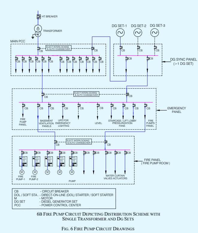
Emergency power supplying distribution system for critical requirement for functioning of fire and life safety system and equipment should be planned for efficient and reliable power and control supply to the following systems and equipment where provided:
a) Fire pumps;
b) Pressurization and smoke venting; including its ancillary systems such as dampers and actuators;
c) Fireman's lifts (including all lifts);
d) Exit signage lighting;
e) Emergency lighting;
f) Fire alarm system;
g) Public address (PA) system (relating to emergency voice evacuation and annunciation);
h) Magnetic door hold open devices; and
j) Lighting in fire command centre and security room.
Power supply to these systems and equipment should be from normal and emergency (standby generator) power sources with changeover facility (see Fig. 6A and Fig. 6B indicating options). If power supply is from HV source and HV generation, the transformer should be planned in standby capacity to ensure continuity of power to such systems. Wherever transformers are installed at higher levels in buildings and backup DG sets are of higher voltage rating, then dual redundant cables should be taken to all transformers. The generator should be capable of taking the starting current of all the fire and life safety systems and equipment as above. Where a parallel HV/LV supply from a separate substation fed from a different grid is provided with an appropriate transformer for emergency, the provision of generator may be waived in consultation with the Authority.
The power supply to the panel/distribution board of these fire and life safety systems should be through fire proof enclosures (tested and certified) or fire survival cables or through alternate route in the adjoining fire compartment to ensure supply of power is reliable to these systems and equipment. It should be ensured that the cabling from the adjoining fire compartment is protected within the compartment of vulnerability. The location of the panel/ distribution board feeding the fire and life safety system should be in fire safe zone ensuring supply of power to these systems.
Circuits of such emergency system should be protected at origin by an automatic circuit breaker with its no-volt coil removed. Master switches controlling essential service circuits should be clearly labelled.
Cables for fire alarm and PA system should be laid in metal conduits or armoured to provide physical segregation from the power cables.
Areas in substation should not be used as storage/dump areas or for other utility purposes other than those required for the functioning of the substation.
The substation area should be adequately ventilated.
An independent, ventilated or air conditioned electrical substation and LT panel room/area should be provided on the ground level or first basement. They should be provided with access from outside (or through exit passageway accessible from outside). The electrical substation and LT panel room/area should be provided with fire resistant walls and doors of fire resistance of not less than 120 min.
If the licensees agree to provide meters on upper floors, the licensees’ cables should be segregated from consumers’ cables by providing a partition in the shaft. Meter rooms on upper floors should not open into staircase enclosures and should be ventilated directly to open air outside or in electrical room of 120 min fire resistant walls.
Electrical MV main distribution panel and lift panels should be provided with CO2/inert gas flooding system for all panel compartments with a cylinder located beside the panel.
A substation or a switch-station with oil filled equipment should be limited to be installed in utility building or in outdoor location. Such substation/utility building should be at least 6 m away (or as per local requirements/actual width of fire driveway) from the adjoining building(s).
Substation equipment (exceeding aggregate oil capacity of 2 000 litre) in utility building should have fire rated baffle walls of 240 min rating constructed between such equipment, raised to at least 600 mm above the height of the equipment (including height of oil conservators/explosion vents) and exceeding 300 mm on each side of the equipment.
All transformers where capacity exceeds 10 MVA should be protected by high velocity water spray systems/ high pressure water mist system. In addition, nitrogen injection systems may also be provided where applicable.
Transformers located inside a building should be of dry type and all substation/switch room walls, ceiling, floor, opening including doors should have a fire resistance rating of 120 min. Access to the substation should be provided from the nearest fire exit/exit staircase for the purpose of electrical isolation.
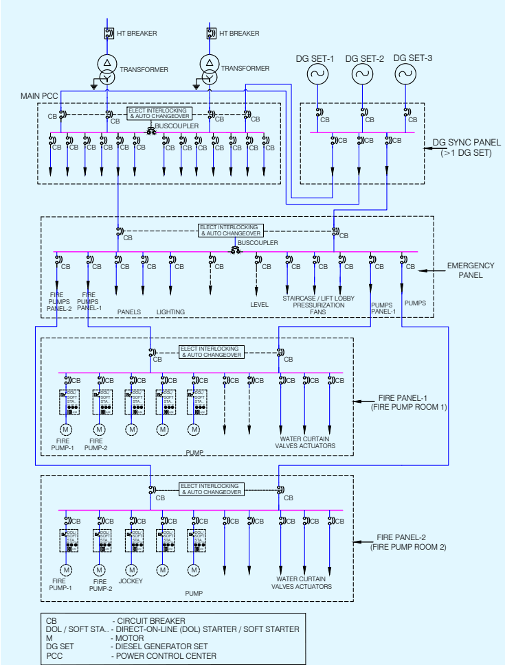
6A FIRE PUMP CIRCUIT DEPICTING DISTRIBUTION SCHEME WITH MULTIPLE TRANSFORMERS AND DG SETS
Diesel generator set(s) should not be installed at any floor other than ground/first basement. If the same are installed indoors, proper ventilation and exhaust should be planned. The DG set room should be separated by 120 min fire resistance rated walls and doors.
The oil tank for the DG sets (if not in the base of the DG) should be provided with a dyked enclosure having a volumetric capacity of at least 10 percent more than the volume of the oil tank. The enclosure should be filled with sand for a height of 300 mm.
See Table 9 for specific fire protection guidelines. For detailed information regarding fire safety requirements for hazardous petroleum products, reference may be made to The Petroleum Act, 1934 and the Rules framed thereunder.
Routing of down conductors (insulated or uninsulated) of lightning protection through electrical or other service shafts are not allowed as it can create fire and explosion during lightning. For details, see Part D ‘Building Services, Section 2 Electrical and Allied Installations’ of this NBCS.
3.5.8.1 Installation of chimney and heating apparatus should be in accordance with good practice [F(10)].
3.5.8.2 Boiler rooms
3.5.8.2.1 Provisions of boiler and boiler rooms should conform to The Boilers Act, 1923.
33
3.5.8.2.2 Further, the following additional aspects may be taken into account in the location of boiler room:
a) The boilers should be installed in a fire resisting room of 180 min fire resistance rating;
b) Entry to this room should be provided with a composite door of 120 min fire resistance rating;
c) The boiler room should be provided with its dedicated natural or mechanical ventilation system. Mechanical ventilation system for the boiler room would be accepted with 120 min fire resistance rating ductwork if it has interface with other mechanical areas. Ventilation system should not be allowed to be routed through electrical room area or through exit corridor/exits; and
d) The oil tank for the boiler should be provided with a dyked enclosure having a volumetric capacity of at least 10 percent more than the volume of the oil tank. The enclosure should be filled with sand for a height of 300 mm.
3.5.4.1 At the time of designing openings in fire-resistant walls and floors, particular attention should be paid to all such factors which limit fire spread through these openings and maintain fire rating of the structural members.
3.5.4.2 For Types 1 to 3 constructions, a doorway or opening in a fire resistant wall on any floor should be limited to 5.6 m2in area with a maximum height/width of 2.75 m. Every wall opening should be protected with fireresisting doors, having the fire rating of not less than 120 min. The openings in the floors should be protected by vertical enclosures extending above and below such openings, such enclosures having a fire resistance of not less than 120 min and all openings therein being protected with a fire-resisting assembly as specified in 3.5.4.6.
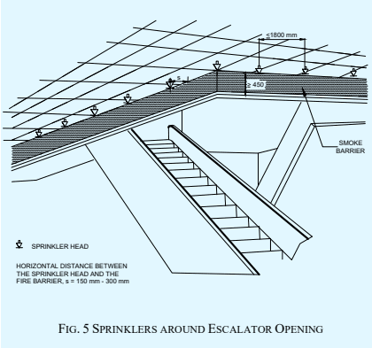
For escalator-like openings, the smoke spill should be avoided by provision of smoke barrier (of 450 mm to 600 mm) thereby creating smoke compartment. Further, the protection should be ensured through installation of sprinklers on all sides of the cut out opening on each floor (see Fig. 5 for details).

3.5.4.3 For Type 4 construction, openings in the fire separating walls or floors should be fitted with 120 min fireresistance rated assemblies.
Openings in walls or floors which are necessary to be provided to allow passages of all building services like cables, electrical wirings, telephone cables, plumbing pipes, etc, should be protected by enclosure in the form of ducts/shafts having a fire resistance not less than 120 min. The inspection door for electrical shafts/ducts should be not less than 120 min, with 30 min insulation. Further, medium, and low voltage wiring running in shafts/ducts, should either be armoured type or run through metal conduits.
The space between the electrical cables/conduits and the walls/slabs should be filled in by a fire stop material {see accepted standard [F(34)]} having fire resistance rating of not less than 120 min. This should exclude requirement of fire stop sealing for low voltage services shaft.
For plumbing shafts in the core of the building, with shaft door opening inside the building, the shafts should have inspection doors having fire resistance rating not less than 30 min.
For plumbing shafts doors which open in wet areas or in naturally ventilated areas or on external wall of the building, the shafts may not require doors having any specified fire rating.
NOTE — In the case of buildings where it is necessary to lower or lift heavy machinery or goods from one floor to the other, it may be necessary to provide larger openings in the floor. Such openings should be provided with removable covers which should have the same strength and fire resistance as the floor.
Refuse chutes, if any provided in a building, should have opening at least 1 m above roof level for venting purpose and they should have an enclosure wall of non-combustible material with fire resistance of not less than 120 min. They should not be located within the staircase enclosure or service shafts, or air conditioning shafts. Refuse chutes inspection panel and doors should be tight fitting with 60 min fire resistance. Sprinkler protection system should be provided for the refuse chutes. Refuse chutes should be at least 3 m away from exits.
Every vertical opening between the floors of a building should be suitably enclosed or protected, as necessary, to provide the following:
a) Reasonable safety to the occupants while using the means of egress by preventing spread of fire, smoke,
or fumes through vertical openings from floor to floor to allow occupants to complete their use of the means of egress. Further it should be ensured to provide a clear height of 2 100 mm in the exit access.
b) Limitation of damage to the building and its contents.

3.5.9.1 The glazing should be in accordance with Part C 'Structural Design, Section 8 Glass and Glazing' of this NBCS. The entire glazing assembly should be rated to that type of construction as given in Table 1. This should be applicable along with other provisions of this Part related to respective uses as specified therein. The use of glass should not be permitted for enclosures of exits and exit passageway.
3.5.9.2 Glass facade should be in accordance with the following:
a) For fully sprinklered buildings having fire separation of 9 m or more, tempered glass in a non-combustible assembly, with ability to hold the glass in place, should be provided. It should be ensured that sprinklers are located within 600 mm of the glass facade providing full coverage to the glass. Where the fire separation is less than 9 m, additional protection such as using a minimum 900 mm spandrel panel of 1 h fire resistance rating should be provided;
NOTE — In case of all other buildings, fire resistance rating of glass facade should be in accordance with Table 1.
b) All gaps between floor-slabs and facade assembly should be sealed at all levels by approved fire resistant sealant material of equal fire rating as that of floor slab to prevent fire and smoke propagation from one floor to another. See also accepted standard [F(35)]; and
c) Openable panels should be provided on each floor and should be spaced not more than 10 m apart measured along the external wall from centre-to-centre of the access openings. Such openings should be operable at a height between 1.2 m and 1.5 m from the floor, and should be in the form of openable panels (fire access panels) of size not less than 1 000 mm × 1 000 mm opening outwards. The wordings, ‘FIRE OPENABLE PANEL — OPEN IN CASE OF FIRE, DO NOT OBSTRUCT’ of at least 25 mm letter height should be marked on the internal side. Such panels should be suitably distributed on each floor based on occupant concentration. These should not be limited to cubicle areas and should be also located in common areas/corridors to facilitate access by the building occupants and fire personnel for smoke exhaust in times of distress.
3.5.10.1 The use of combustible surface finishes on walls (including facade of the building) and ceilings affects the safety of the occupants of a building. Such finishes tend to spread the fire and even though the structural elements may be adequately fire resistant, serious danger to life may result. It is, therefore, essential to have adequate precautions to minimize spread of flame on wall, facade of building and ceiling surfaces. The finishing materials used for various surfaces and decor should be such that it should not generate toxic smoke/fumes.
3.5.10.2 The susceptibility of various types of wall surfaces to fire is determined in terms of the rate of spread of flame. Based on the rate of spread of flame, surfacing material should be considered as divided into four classes as follows {see also good practice [F(11)]}:
a) Class 1 Surfaces of very low flame spread;
b) Class 2 Surfaces of low flame spread;
c) Class 3 Surfaces of medium flame spread; and
d) Class 4 Surfaces of rapid flame spread.
3.5.10.3 The uses for which surface materials falling into various classes should be adopted in building construction are given below:
| Class 1(1) | Class 2(2) | Class 3(3) |
|---|---|---|
| May be used in any situation | May be used in any situation, except on walls, facade of the building, staircase, and corridors | May be used only in living rooms and bed rooms (but not in rooms on the roof) and only as a lining to solid walls and partitions; not on staircases or corridors or facade of the building. |
NOTE — Panelling (lining) may be permitted in a limited area; and is not to be permitted in a vestibule.
3.5.10.4 Materials of Class 4 which include untreated wood fibreboards may be used with due fire-retardant treatment as ceiling lining, provided the ceiling is at least, 2.4 m from the top surface of the floor below, and the wall surfaces conform to requirements of the class [see Note under 3.5.10.3]. Class 4 materials should not be used in kitchens, corridors, and staircases. Some materials contain bitumen and, in addition to risk from spread of fire, emit dense smoke on burning; such materials should be excluded from use under these conditions and should also not be used for construction of ceiling where the plenum is used for return air in air-conditioned buildings.
3.5.10.5 When frames, walls, partitions, or floors are lined with combustible materials, the surfaces on both sides of the materials should conform to the appropriate class, because there is considerable danger from fire starting and rapidly spreading within the concealed cavity unknown to the occupants whose escape may be hampered thereby. For detailed information on materials and details of construction with their fire resistance rating, reference may be made to good practice [F(12)].
3.5.10.6 The use of aluminium composite panels as external facade of the buildings should be avoided; if used, such panels should have a minimum of 70 percent mineral core and pass the tests as in accepted standards (see Note 2).
NOTES
1 When combustible materials are used for lining frames, walls, partitions, or floors, the surfaces on both sides of the materials must meet the required fire resistance class. This precaution helps mitigate the risk of fire spreading within concealed cavities, which may not be immediately visible to occupants and can hinder evacuation.
2 Accepted standards can be ISO 3957 or ISO 13785 (Part 1 and Part 2).
3.5.7.1 Air conditioning and mechanical ventilation requirements of different rooms or areas in any occupancy should be as given in Part D ‘Building Services, Section 1 Lighting and Natural Ventilation' and ‘Section 3 Air conditioning, Heating and Mechanical Ventilation’ of this NBCS.
Air conditioning and ventilating systems should be so installed and maintained as to minimize the danger of spread of fire, smoke, or fumes from one floor to another or from outside to any occupied building or structure.
Many high-rise buildings integrate smoke management systems into their conventional HVAC systems. In such installation, it requires special design considerations, including safe and adequate controls, acceptable and documented testing, and regular maintenance systems.
Wherever batteries are provided, the same should be segregated by 120 min fire rated construction. Ventilation to the room should be provided as per manufacturer's instructions.
3.5.7.2.1 From fire safety point of view, separate air handling units (AHU) for each floor should be provided so as to avoid the hazards arising from spread of fire and smoke through the air conditioning ducts. The air ducts should be separate from each AHU to its floor and in no way should interconnect with the duct of any other floor. Within a floor it would be desirable to have separate air handling unit provided for each compartment.
Air handling unit should be provided with effective means for preventing circulation of smoke through the system in the case of a fire in air filters or from other sources drawn into the system, and should have smoke sensitive devices for actuation in accordance with the accepted standard [F(8)] and control.
3.5.7.2.2 Shafts or ducts, if penetrating multiple floors, should be of masonry construction with fire damper in connecting ductwork or should have fire rated ductwork with fire dampers at floor crossing. Alternatively, the duct and equipment may be installed in room having walls, doors and fire damper in duct exiting/entering the room of 120 min fire resistance rating. Such shafts and ducts should have all passive fire control meeting 120 min fire resistance rating requirement to meet the objective of isolation of the floor from spread of fire to
upper and lower floors through shaft/duct work.
NOTE — Zoned and compartmented HVAC systems are encouraged with an approach to avoid common exhaust shafts and fresh air intake shafts which will limit the requirement of such passive measure and fire rated duct work and dampers.
3.5.7.2.3 The air filters of the air handling units should be made of non-combustible materials.
3.5.7.2.4 The air handling unit room should not be used for storage of any combustible materials.
3.5.7.3.1 Air ducts serving main floor areas, corridors, etc, should not pass through the fire exits/exit passageway/ fire exit enclosure. Fire exits and lift lobbies, etc, should not be used as return air passage.
3.5.7.3.2 As far as possible, metallic ducts (of suitable rating) should be used even for the return air instead of space above the false ceiling.
3.5.7.3.3 Wherever the ducts pass through fire walls or floors, the opening around the ducts should be sealed with materials having fire resistance rating of the compartment {see accepted standard [F(34)]}. Such duct should also be provided with fire dampers at all fire walls and floors unless such ducts are required to perform for fire safety operation; and in such case fire damper may be avoided at fire wall and floor while integrity of the duct should be maintained with 120 min fire resistance rating to allow the emergency operations for fire safety requirements.
3.5.7.3.4 The ducting within compartment would require minimum fire resistance rating of 30 min. Such ducting material in substantial gauge should be in accordance with good practice [F(9)]. If such duct crosses adjacent compartment/floor and not having fire dampers in such compartment/floor, it would require fire resistance duct work rating of 120 min. The requirements of support of the duct should meet its functional time requirement as above.
3.5.7.3.5 The materials used for insulating the duct system (inside or outside) should be of non-combustible type. Any such insulating material should not be wrapped or secured by any material of combustible nature.
3.5.7.3.6 Inspection panels should be provided in the ductwork to facilitate the cleaning of accumulated dust in ducts and to obtain access for maintenance of fire dampers.
3.5.7.4.1 These dampers should be evaluated to be located in supply air ducts, fresh air and return air ducts/ passages at the following points:
a) At the fire separation wall,
b)Where ducts/passages enter the vertical shaft,
c) Where the ducts pass through floors, and
d) At the inlet of supply air duct and the return air duct of each compartment on every floor.
3.5.7.4.2 Damper should be of motorized type/fusible link. Damper should be so installed to provide complete integrity of the compartment with all passive fire protection sealing. Damper should be accessible to maintain, test and also replace, if so required. Damper should be integrated with fire alarm panel and should be sequenced to operate as per requirement and have interlocking arrangement for fire safety of the building. Manual operation facilities for damper operation should also be provided. Tested and certified dampers for dynamic condition are preferable.