3.5.5.1 For requirements regarding electrical installations from the point of view of fire safety, reference may be made to good practice [F(6)] and Part D ‘Building Services, Section 2 Electrical and Allied Installations’ of this NBCS.
In general, it is desirable that the wiring and cabling are with flame retardant property. Medium and low voltage wiring running in shafts, and within false ceiling should run in metal conduit. Any 230 V wiring for lighting or other services, above false ceiling, should have 660 V grade insulation. See also Part D/Sec 2 for wires having options of fire resistance.
The electric distribution cables/wiring should be laid in a separate shaft. The shaft should be sealed at every floor with fire stop materials, see accepted standard [F(34)] having the same fire resistance as that of the floor. High, medium, and low voltage wiring running in shaft and in false ceiling should run in separate shaft/conduits.
Water mains, gas pipes, telephone lines, intercom lines or any other service line should not be laid in the duct for electrical cables; use of bus ducts/solid rising mains instead of cables is preferred.
All metallic items like steel structural members, etc, should be bonded properly to the earthing system.
3.5.5.2 Emergency power for fire and life safety systems
Emergency power supplying distribution system for critical requirement for functioning of fire and life safety system and equipment should be planned for efficient and reliable power and control supply to the following systems and equipment where provided:
a) Fire pumps;
b) Pressurization and smoke venting; including its ancillary systems such as dampers and actuators;
c) Fireman's lifts (including all lifts);
d) Exit signage lighting;
e) Emergency lighting;
f) Fire alarm system;
g) Public address (PA) system (relating to emergency voice evacuation and annunciation);
h) Magnetic door hold open devices; and
j) Lighting in fire command centre and security room.
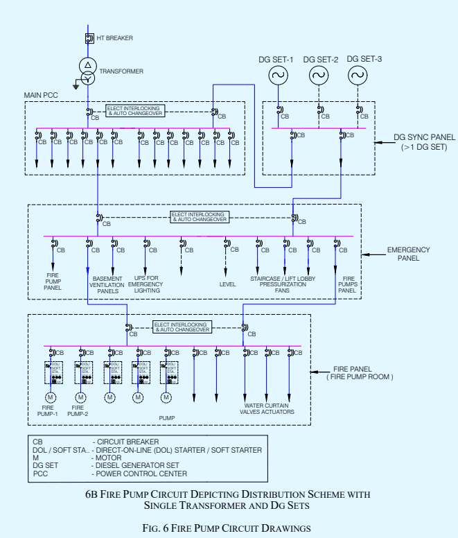
Power supply to these systems and equipment should be from normal and emergency (standby generator) power sources with changeover facility (see Fig. 6A and Fig. 6B indicating options). If power supply is from HV source and HV generation, the transformer should be planned in standby capacity to ensure continuity of power to such systems. Wherever transformers are installed at higher levels in buildings and backup DG sets are of higher voltage rating, then dual redundant cables should be taken to all transformers. The generator should be capable of taking the starting current of all the fire and life safety systems and equipment as above. Where a parallel HV/LV supply from a separate substation fed from a different grid is provided with an appropriate transformer for emergency, the provision of generator may be waived in consultation with the Authority.
The power supply to the panel/distribution board of these fire and life safety systems should be through fire proof enclosures (tested and certified) or fire survival cables or through alternate route in the adjoining fire compartment to ensure supply of power is reliable to these systems and equipment. It should be ensured that the cabling from the adjoining fire compartment is protected within the compartment of vulnerability. The location of the panel/ distribution board feeding the fire and life safety system should be in fire safe zone ensuring supply of power to these systems.
Circuits of such emergency system should be protected at origin by an automatic circuit breaker with its no-volt coil removed. Master switches controlling essential service circuits should be clearly labelled.
Cables for fire alarm and PA system should be laid in metal conduits or armoured to provide physical segregation from the power cables.
Areas in substation should not be used as storage/dump areas or for other utility purposes other than those required for the functioning of the substation.
The substation area should be adequately ventilated.
An independent, ventilated or air conditioned electrical substation and LT panel room/area should be provided on the ground level or first basement. They should be provided with access from outside (or through exit passageway accessible from outside). The electrical substation and LT panel room/area should be provided with fire resistant walls and doors of fire resistance of not less than 120 min.
If the licensees agree to provide meters on upper floors, the licensees’ cables should be segregated from consumers’ cables by providing a partition in the shaft. Meter rooms on upper floors should not open into staircase enclosures and should be ventilated directly to open air outside or in electrical room of 120 min fire resistant walls.
Electrical MV main distribution panel and lift panels should be provided with CO2/inert gas flooding system for all panel compartments with a cylinder located beside the panel.
3.5.5.3.1 Oil filled substation
A substation or a switch-station with oil filled equipment should be limited to be installed in utility building or in outdoor location. Such substation/utility building should be at least 6 m away (or as per local requirements/actual width of fire driveway) from the adjoining building(s).
Substation equipment (exceeding aggregate oil capacity of 2 000 litre) in utility building should have fire rated baffle walls of 240 min rating constructed between such equipment, raised to at least 600 mm above the height of the equipment (including height of oil conservators/explosion vents) and exceeding 300 mm on each side of the equipment.
All transformers where capacity exceeds 10 MVA should be protected by high velocity water spray systems/ high pressure water mist system. In addition, nitrogen injection systems may also be provided where applicable.
3.5.5.3.2 Dry type substation
Transformers located inside a building should be of dry type and all substation/switch room walls, ceiling, floor, opening including doors should have a fire resistance rating of 120 min. Access to the substation should be provided from the nearest fire exit/exit staircase for the purpose of electrical isolation.
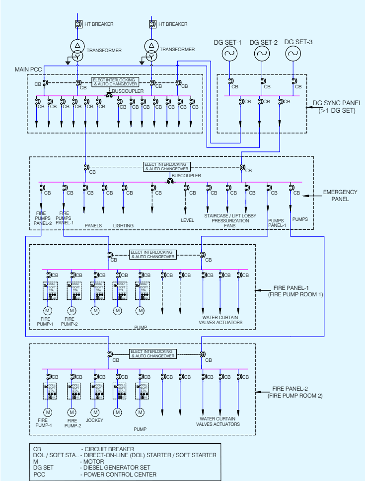
6A FIRE PUMP CIRCUIT DEPICTING DISTRIBUTION SCHEME WITH MULTIPLE TRANSFORMERS AND DG SETS
3.5.5.4 Standby supply
Diesel generator set(s) should not be installed at any floor other than ground/first basement. If the same are installed indoors, proper ventilation and exhaust should be planned. The DG set room should be separated by 120 min fire resistance rated walls and doors.
The oil tank for the DG sets (if not in the base of the DG) should be provided with a dyked enclosure having a volumetric capacity of at least 10 percent more than the volume of the oil tank. The enclosure should be filled with sand for a height of 300 mm.
See Table 9 for specific fire protection guidelines. For detailed information regarding fire safety requirements for hazardous petroleum products, reference may be made to The Petroleum Act, 1934 and the Rules framed thereunder.
3.5.5.5 Lightning protection of buildings
Routing of down conductors (insulated or uninsulated) of lightning protection through electrical or other service shafts are not allowed as it can create fire and explosion during lightning. For details, see Part D ‘Building Services, Section 2 Electrical and Allied Installations’ of this NBCS.