Voltage drop in the electrical system is the direct indicator of the system resistance. It represents the energy loss in the system which is dissipated
in the form of heat. As the length of the wire increases its resistance increases. Therefore, higher the resistance(R), more will be the voltage drop. If the current increases, there will be further losses.
The Code defines two types of conductors (Figure 7.19).
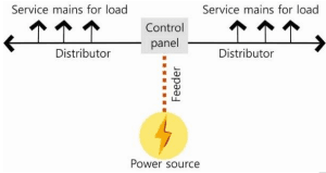
Figure 7.19 Feeder and distributors
Feeders
Feeder conductors run between the service entrance equipment (where the power enters the building) and the branch circuit distribution equipment (e.g., circuit breaker). Feeder circuits use thicker cables that travel from the main entrance panel to smaller distribution panels called subpanels, or load centers.
Branch circuit conductors run from the final circuit breaker to the load. In some small buildings, all wiring will be branches running from the main electrical service. Distributor will have multiple tapping for supplying the power to multiple loads.
Voltage drop is dependent on the following:
Circuit type (single-phase or three phase)
Number and size of conductors per phase
• Conduit types (magnetic or nonmagnetic)
Power factor of the load
Circuit length
• Load current
As per the code,
Voltage drop for feeders shall not exceed 2% at design load. Voltage drop for branch circuit shall not exceed 3% at design load.
Issue with voltage drop
In most electrical circuits the current increases as voltage at the load drops because the load requires a certain amount of power. When the current increases, there is an increase in the power loss within the conductor that varies as the square of the current ( P = I 2 R ) . Therefore, the voltage drop is an energy efficiency issue. Hence the Code requires that the voltage drop is controlled.
Further, the voltage drop in the conductors, if excessive, may result in equipment operation problems or equipment failure.