The purpose of this guide is to help the users understand the intent, requirement and potential application of the Code. It intends to demystify the Code. It is intended for users who might not be aware of all the technical requirements covered in the Code
Throughout the Code, there are examples and case studies given with the aim of reinforcing the concepts.
The User Guide follows the same structure (including the section numbers) as the Energy Conservation Building Code. It has been written in an easy to understand format using simple language supported by graphics.
Text shown in Blue is a direct excerpt from the ECBC document and is likely to serve as an anchor for the explanation given in different chapters.
ii
1.PURPOSE
The purpose of the Energy Conservation Building Code (Code) is to provide minimum requirements for the energy-efficient design and construction of buildings. The Code provides two additional sets of incremental requirements for buildings to achieve enhanced levels of energy efficiency that go beyond the minimum requirements.
The building sector represents about 33% of electricity consumption in India, with commercial sector and residential sector accounting for 8%and 25% respectively. Estimates based on computer simulation models indicate that ECBC-compliant buildings can use 40% to 60% less energy than conventional buildings. It is estimated that the nationwide mandatory enforcement of the ECBC will yield annual savings of approximately 1.7 billion kWh. The ECBC is expected to overcome market barriers, which otherwise result in underinvestment in building energy efficiency.
The ECBC was developed as a first step towards promoting energy efficiency in the building sector. The ECBC (also referred to as “The Code” in this document) is the result of extensive work by the Bureau of Energy Efficiency (BEE) and its Committee of Experts. It is written in codeenforceable language and addresses the views of the manufacturing, design, and construction communities as an appropriate set of minimum requirements for energy-efficient building design and construction.
For developing the Code, building construction methods across the country were reviewed and various energy efficient design and construction practices were evaluated that could reduce energy consumption in building. In addition,
detailed life-cycle cost analyses were conducted to ensure that the Code requirements reflect cost effectiveness and practical efficiency measures across five different climate zones in India. While taking into account different climate zones, the Code also addresses site orientation and specifies better design practices and technologies that can reduce energy consumption without sacrificing comfort and productivity of the occupants.
The ECBC User Guide (also referred to as “The Guide” in this document) has been developed to provide detailed guidance to building owners, designers, engineers, builders, energy consultants, and others on how to comply with the Code. It provides expanded interpretation, examples, and supplementary information to assist in applying ECBC during the design and construction of new buildings as well as additions and alterations to existing buildings. This Guide can also be used as a document by “authorities having jurisdiction” in the enforcement of the Code once it is made mandatory. The Guide follows the nomenclature of the Code. It is written both as a reference and as an instructional guide, that can be helpful for anyone who is directly or indirectly involved in the design and construction of ECBC-compliant buildings.
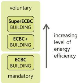
increasing level of energy efficiency
2.SCOPE
The Code is applicable to buildings or building complexes that have a connected load of 100 kW or greater or a contract demand of 120 kVA or greater and are intended to be used for commercial purposes.
Buildings intended for private residential purposes only are not covered by the Code.
Generally, buildings or complexes having conditioned area of 500 m2 or more will fall under this category.
The Code is presently under voluntary adoption in the country.
This Code would become mandatory as and when it is notified by the Central and State government in the official Gazette under clause (p) of §14 or clause (a) of §15 of the Energy Conservation Act 2001 (52 of 2001).
Energy Efficiency Performance Levels
In addition to Code compliance, ECBC has introduced two voluntary performance thresholds for buildings that choose to go beyond Code and achieve higher energy performance (Figure 2.1).
The materials and technology to design a high performance building is available in the market today. The first cost might be higher, but the life cycle cost is lower. In the near future, market transformation will make high performance buildings mainstream. This will further help in the smooth transition to the next technical update of the Code with higher stringency levels eventually leading the country towards the netzero energy goal.
Figure 2.1 Energy efficiency performance levels
The code prescribes the following three levels of energy efficiency:
(a) Energy Conservation Building Code Compliant Building (ECBC Building)
The Code compliant building will incorporate all the minimum requirements as enumerated in the Code. Buildings that are in the purview of the Code will have to be an ECBC building at the minimum.
ECBC Buildings shall demonstrate compliance by adopting the mandatory and prescriptive requirements listed under ECBC Compliant Building requirements in §4 to §7, or by following the provisions of the Whole Building Performance (WBP) Method in §0.
(b) Energy Conservation Building Code Plus Building (ECBC+ Building)
This is the first threshold of performance beyond Code compliance.
ECBC+ Buildings shall demonstrate compliance by adopting the mandatory and prescriptive requirements listed under ECBC+ Compliant Building requirements §4 to §7, or by following the provisions of the
Whole Building Performance (WBP) Method in §0.
(c) Super Energy Conservation Building Code Building (SuperECBC Building)
This is the second and highest threshold of performance beyond Code compliance. High performance buildings can aim to meet the SuperECBC requirements.
SuperECBC Buildings shall demonstrate compliance by adopting the mandatory and prescriptive requirements listed under SuperECBC Compliant Building requirements in §4 to §7, or by following the provisions of the Whole Building Performance (WBP) Method in §0.
security, health, or environment by Central, State, or Local Government.
(b) Bureau of Energy Efficiency’s Standards and Labelling for appliances and Star Rating Program for buildings, provided both or either are more stringent than the requirements of this Code.
Largely, technology update takes place faster than technical updates in the Code. It is important for a Code to stay current to achieve it larger goals of energy efficiency over time. Thus, to keep the Code dynamic, the above-mentioned codes, programs and policies have been included so that the latest in the technological requirements will take precedence as when it is introduced.
2.2 Building Systems
The provisions of this code apply to:
(a) Building envelope,
(b) Mechanical systems and equipment, including heating, ventilating, and air conditioning, service hot water heating,
(c) Interior and exterior lighting, and
(d) Electrical power and motors, and renewable energy systems.
The provisions of this code do not apply to plug loads, and equipment and parts of buildings that use energy for manufacturing processes, unless otherwise specified in the Code.
2.3Precedence
The following codes, programs, and policies will take precedence over the Code in case of conflict:
(a) Any policy notified as taking precedence over this Code, or any other rules on safety,
Reference Standards
The National Building Code of India 2016 (NBC) is the reference standard for lighting levels, heating, ventilating, and air conditioning (HVAC), thermal comfort conditions, natural ventilation, and any other building materials and system design criteria addressed in this Code.
Building Classification
There are many different types of commercial buildings that fall under the purview of the Code. These buildings are different from each other in basic typology, usage of spaces and occupancy. For example, a school is fundamentally a different kind of building compared to a hotel which is again very different compared to an office. Hence, the Code has requirements for different kind of buildings.
Energy efficiency requirements for the Code were derived after analysing 16 different non-residential building typologies, that in turn are broadly based on building classification in the National Building Code of India. Spatial layouts, material specifications, façade characteristics,
and occupancy patterns have an impact on energy efficiency of a building and differ for these typologies.
Potential for reducing energy use with technology and materials thus varies from building type to type. By analysing this potential, ECBC energy efficiency requirements are now sensitive to building typologies and, to the extent possible, only requirements that are feasible have been included.
Any one or more building or part of a building with commercial use is classified as per the functional requirements of its design, construction, and use. The key classification is as below:
(a) Hospitality: Any building in which sleeping accommodation is provided for commercial purposes, except any building classified under Health Care. Buildings and structures under Hospitality shall include the following:
i. No-star Hotels – like Lodging-houses, dormitories, no-star hotels/motels
ii. Resort
iii. Star Hotel
(b) Health Care: Any building or part thereof, which is used for purposes such as medical or other treatment or care of persons suffering from physical or mental illness, disease, or infirmity; care of infants, convalescents, or aged persons, and for penal or correctional detention in which the liberty of the inmates is restricted. Health Care buildings ordinarily provide sleeping accommodation for the occupants. Buildings and structures like hospitals, sanatoria, outpatient healthcare, laboratories, research establishments, and test houses are included under this type.
(c) Assembly: Any building or part of a building, where number of persons congregate or
gather for amusement, recreation, social, religious, patriotic, civil, travel and similar purposes. Buildings like theatres or motion picture halls, gathering halls, and transport buildings like airports, railway stations, bus stations, and underground and elevated mass rapid transit system are included in this group.
(d) Business: Any building or part thereof which is used for transaction of business, for keeping of accounts and records and similar purposes, professional establishments, and service facilities. There are two subcategories under Business – Daytime Business and 24-hour Business. Unless otherwise mentioned, Business buildings shall include both Daytime and 24-hour subcategories.
(e) Educational: Any building used for schools, colleges, universities, and other training institutions for day-care purposes involving assembly for instruction, education, or recreation for students. If residential accommodation is provided in the schools, colleges, or universities or coaching/ training institution, that portion of occupancy shall be classified as a No-star Hotel. Buildings and structures under Educational shall include following types-
i. Schools
ii. Colleges
iii. Universities
iv. Training Institutions
(f) Shopping Complex: Any building or part thereof, which is used as shops, stores, market, for display and sale of merchandise, either wholesale or retail. Buildings like shopping malls, stand-alone retails, open gallery malls, super markets, or hyper markets are included in this type.
(g) Mixed-use Building: In a mixed-use building, each commercial part of a building must be classified separately, and –
If a part of the mixed-use building has different classification and is less than 10% of the total above grade floor area, the mixed-use building shall show compliance based on the building subclassification having higher percentage of above grade floor area.
ii. If a part of the mixed-use building has different classification and one or more sub-classification is more than 10% of the total above grade floor area, the compliance requirements for each subclassification, having area more than 10% of above grade floor area of a mixed-use building shall be determined by the requirements for the respective building classification in §4 to §7.
Any building which does not fall under any of the categories defined above shall be classified in a category mentioned above that best describes the function of the building.
Example 2-A
A new airport is coming up in a city. What building typology will it be considered for ECBC compliance?
As per §2.5, the airport will be classified as an ‘Assembly’ building type.
Example 2-B
A university campus has the following buildings.
Library
Hostel blocks
Faculty housing
Engineering college
Sports complex
Identify which buildings are applicable for ECBC compliance
All buildings on this campus are applicable for ECBC compliance. The hostel blocks and faculty housing, although are residential, but they are intended for a commercial purpose. These buildings are not considered as private residence. Hence will be applicable for Code compliance.
Example 2-C
A project having a built-up area of 100,000 sqm includes the following types of buildings
• 2 storey shopping complex
• 3 storey mall
• 10 storey office block
4 blocks of 15 storey residential buildings
Will this project be applicable for Code compliance? Identify the building typology as per the Code for this project.
The residential buildings in the project are considered as a ‘private residence’. Hence, they are not included in the scope of ECBC. All remaining buildings are applicable for Code compliance.
This project will be classified as a ‘mixeduse Building’ as per §2.5 where individual buildings will be classified as follows.
2 storey shopping complex – Shopping complex
• 3 storey mall – shopping complex
• 10 storey office block - Business
Each of these buildings will have to comply with the requirements for the specific building type as per the Code.
Compliance and Approach
This section enumerates the overall compliance and administrative requirements for demonstrating compliance with the Code. The technical requirements are covered in detail in the subsequent chapters.
SECTION ORGANIZATION
COMPLIANCE
APPROACH
MEET MANDATORY REQUIREMENTS
PRESCRIPTIVE METHOD
DETERMINE EPI RATIOS
BUILDING ENVELOPE TRADE-OFF METHOD
WHOLE BUILDNG PERFORMANCE METHOD
3.COMPLIANCE and Approach
3.1General
While ECBC is adopted as a national Code, the State governments can have some additional or amended requirements. Hence, when using this manual, one should check with the adopting jurisdiction for supplemental information on compliance.
To comply with Code, buildings needs to meet the following two requirements.
Comply with the mandatory requirements as per §4.2, §5.2, §6.2 and §7.2 AND
Determine the Energy Performance Index Ratio (EPI ratio) as defined in §3.1.2. To comply with the Code, buildings shall have an EPI ratio less than or equal to 1.
Determining the EPI ratio for all buildings is a major update in the Code. The EPI ratio provides a means to quantify energy performance of building. Just being Code compliant does not communicate how well the building is performing.
For example, a building having a EPI ratio of 1 denotes a Code compliant building meeting the minimum requirements. While a EPI ratio of 0.9 denotes that the building is 10% more energy efficient than a Standard Code compliant building.
Measuring energy efficiency also helps in setting goals for a better performance. For example, achieving a EPI ratio of 0.5 can be a project goal, but being Code compliant is a requirement and not a goal.
EPI ratio clearly recognizes buildings going beyond Code compliance. The intent of including the EPI ratio is to encourage project proponents to aim for better energy performance beyond Code compliance.
Energy Performance Index
The Energy Performance Index (EPI) is a benchmark to measure the energy performance of a building. It is the annual energy consumption in kilowatt-hours per square meter of the building. EPI can be determined by:
annual energyEPI=total built - up area (excludingconsumption in kWhunconditioned basements)
Lower EPI denotes a lower energy use and hence a better performance. Buildings should target to achieve as low a EPI as possible. The EPI will have to be defined first before determining the EPI Ratio.
LOWER EPI DENOTES A LOWER ENERGY USE AND HENCE A BETTER PERFORMANCE
Determining EPI
While calculating the EPI of a proposed building, the area of unconditioned basements shall not be included.
EPI can be determined by either of the following methods
(a) Prescriptive Method including Building Envelope Trade-off Method (see §3.2.2)
(b) Whole Building Performance Method (see §3.2.3)
If a building is opting for the prescriptive path for ECBC compliance, then it shall use the same method to determine the EPI as well.
Determining EPI Ratio
The EPI Ratio of a building is the ratio of the EPI of the Proposed Building to the EPI of the Standard Building:
EPIRatio=EPI of Standard BuildingEPI of Proposed Building
where,
Proposed Building is consistent with the actual design of the building and complies with all the mandatory requirements of ECBC.
A Standard Building is defined for comparing the performance of the proposed building. A standard building is defined as having the same building floor area, gross wall area and gross roof area as the Proposed Building. It complies with the mandatory requirements §4.2, §5.2, §6.2 and §7.2 and meets the minimum prescriptive requirements of §4.3, §5.3 and §6.3 for ECBC Buildings.
EPI ratio can be determined by either of the following methods
(a) Prescriptive Method including Building Envelope Trade-off Method (see §3.2.2)
(b) Whole Building Performance Method (see §3.2.3)
Example 3-A
A commercial core and shell building for office use is ECBC compliant. The tenant lease agreement states that the maximum allowable interior lighting power is 9.5 W/m2. The tenant has designed the space such that the lighting power density is 8.0 W/m2. Is the tenant complying with the lease agreement?
Lower lighting power indicates less energy use. Thus, exceeding the maximum allowable lighting power will lead to non-compliance. Since the tenant has achieved a lighting power density lower than the requirement, the tenant space is in compliance with the lease agreement.
EPI Ratio for Mixed-use Development
A mixed-used building can have more than one type of building within the same structure. For example, strip retail on the ground floor and offices in the above stories of the same building. In such cases, the EPI Ratio of a mixed-use Proposed Building shall be calculated based on area-weighted average method.
EPI Ratio for Core and Shell Buildings
In a core and shell building, the developer is typically responsible for the design of common areas in the base building. This could include providing mechanical, electrical and plumbing services as appropriate in areas such as lobby, corridors, restrooms, staircase and others. The tenants could have different systems installed in the area occupied by them. Hence the EPI ratio for a core and shell building shall be calculated only for the common areas using the following method
(a) Prescriptive Method including Building Envelope Trade-off Method (see §0)
(b) Whole Building Performance Method (see §Error! Reference source not found.)
Further, it is required to get a relevant undertaking from the tenants with the technical requirements clearly mentioned in the tenant lease agreement in order to comply with Code.
As per the Code,
EPI for core and shell buildings shall be calculated for the entire building based on the final design of the common areas and the relevant mandatory undertaking(s) in the tenant lease agreement for the leased areas, as per §3.1.2 or §Error! Reference source not found..
Steps to calculate the EPI ratio for a mixed-use building
Classify each commercial part of the mixed-used building as listed in §9.5.
Determine the percentage of area of each classification as per the total above grade area (AGA).
Area weightage of the sub classification=total above grade area (AGA)area of the sub classification∗100
If the sub classification is less than 10% of the total above grade area (AGA), then consider the EPI ratio of the sub-classification having highest percentage of above grade floor area.
If the sub classification is more than 10% of the total above grade area (AGA), then consider the EPI ratio of all the individual sub-classifications.
In both cases, the EPI Ratio of the mixed-use Proposed Building shall be less than or equal to Maximum Allowed EPI listed in Table 9-5 through Table 9-9.
Exceptions to the above: Any portion of a mixed-use building classified in a category which does not fall under the scope of ECBC is exempted from demonstrating compliance.
For example, a mixed-use building can have multi-family residential units and commercial spaces combined in one building. In that case, the residential units will be excluded from the scope of ECBC and the commercial part of the building will be considered for complying with the corresponding EPI ratio. If there are more than one type of spaces within the commercial part, say a supermarket and a strip retail shops, then the EPI ratio for this mixed-use commercial part should be calculated as per the area-weighted average method as explained in the above section.
Example 3-B
A 10-story commercial building project in a hot-dry climate is taking the prescriptive approach to comply with ECBC. This mixeduse building has 3 stories of shopping complex and 7 stories of office building (regular use). What is the EPI ratio this building needs to comply with?
For the prescriptive approach, the EPI ratio will be 1 for both building types.
Note: In the case of Whole Building Performance Method, two Standard Buildings need to be defined – one for the shopping mall and the other for office building so that the Proposed Building can be compared to respective Standard Building to determine the corresponding EPI ratios.
Example 3-C
A 10-story commercial building project in a hot-dry climate is taking the prescriptive approach to comply with ECBC. This mixeduse building has 3 stories of shopping complex and 7 stories of office building (regular use). What is the EPI ratio this building needs to comply with to achieve the ECBC+ performance level?
Step 1: Since this is a mixed-use building, each commercial part needs to be first classified as per §9.5. This building has the following types of buildings
shopping mall
office building (regular use)
Step 2: find out the percentage of area relative to the AGA Shopping mall – 30% Office building – 70%
Step 3: Since each sub-classification is greater than 10%, EPI ratios for each building type should be considered as per Error! Reference source not found. for hotdry climate.
Thus, EPI ratio of shopping mall = 0.84 EPI ratio of office (regular use) = 0.86
If the mixed-use building meets the prescriptive requirements as per §4.3, §5.3, §Error! Reference source not found., §Error! Reference source not found. and §6.3 for the respective building type, it will be deemed to have a EPI ratio of 0.84 for the shopping mall and 0.86 for the office.
Compliance Approaches
Buildings that fall within the scope of the Code as mentioned in §2, shall comply with the Code by meeting all the mandatory requirements (see §3.2.1) using any of the compliance paths mentioned in §3.2.2 or §3.2.3.
Buildings shall comply with all mandatory requirements mentioned under §4.2, §5.2, §6.2 and §7.2, irrespective of the compliance path.
3.2.2.2Building Envelope Trade-off Method
The design of the building envelope generally demands more flexibility. The Building Envelope Trade-off Method offers some flexibility to the prescriptive approach where improvement in one component can compensate for the lack of it in another component within the building envelope only.
Building Envelope Trade-off Method may be used in place of the prescriptive criteria of §4.3.1, §0 and §4.3.3. A building complies with the Code using the Building Envelope Trade-off Method if the Envelope Performance Factor (EPF) of the
Proposed Building is less than or equal to the EPF of the Standard Building, calculated as per §4.3.5, in addition to meeting the prescriptive requirements for comfort systems and controls (§5.3, §Error! Reference source not found., §Error! Reference source not found.), and lighting and controls (§6.3), and all the mandatory requirements (§4.2, §5.2, §6.2 and §7.2).
Prescriptive Method
A building complies with the Code using the Prescriptive Method if it meets the prescribed minimum (or maximum) values for envelope components (§4.3), comfort systems and controls (§5.3, §Error! Reference source not found., §Error! Reference source not found.), and lighting and controls (§6.3), in addition to meeting all the mandatory requirements.
This approach does not offer much flexibility in design compared to the Whole Building Performance Method since the prescribed values for individual elements need to be met.
3.2.2.1 EPI Ratio through Prescriptive Method
In the prescriptive approach, the energy use of a building cannot be quantified in absolute terms. However, the performance can be compared to a Standard building and expressed as EPI ratio. As per the Code,
ECBC Buildings that demonstrate compliance through Prescriptive Method (§3.2.2) shall be deemed to have an EPI equal to the Standard Building EPI, and therefore an EPI Ratio of 1.
Thus, the EPI ratio of ECBC building is 1 for all building types across all climate types because it is equal to the Standard Building for the
corresponding building and climate type. EPI ratio of 1 denotes that the building has met the minimum set of requirements for Code compliance.
EPI Ratio of Ecbc Building IS 1
As per the Code, ECBC+ Buildings and SuperECBC Buildings that demonstrate compliance through Prescriptive Method shall be deemed to have an EPI Ratio equal to the EPI Ratios listed in §9.5 under the applicable building type and climate zone.
Thus, EPI ratios of ECBC+ and SuperECBC buildings are always less than 1. It varies from 0.91 to 0.66 for specific building types in different climate zones as per §9.5. For example, the EPI ratio for a supermarket in a composite climate is 1 for Code compliance. If the same building aims for a ECBC+ performance, then the maximum allowed EPI ratio is 0.81 and for the SuperECBC performance level, it is 0.68. This means, the SuperECBC building is 32% more energy efficient than a Code compliant ECBC building.
3.2.2.3Total System Efficiency Method
Just like the building envelope, the airconditioning systems also demand more flexibility in design, especially in the case of a chilled water plant in large buildings. The Code offers flexibility to comply with efficiency at the plant level rather than comply with requirements of individual components.
As per Code,
For projects using central chilled water plants, the Total System Efficiency approach may be used to comply with the Prescriptive Method of §5. This approach may be used in place of the prescriptive criteria of chillers (§5.3.1 and §5.3.6), chilled water pumps (§5.3.2), condenser water pumps (§5.3.2), and cooling tower fan (§5.3.3). Per this approach, a building complies if the Total System Efficiency thresholds are met as per Table 5-23 Maximum System Efficiency Threshold for ECBC, ECBC+, and SuperECBC Buildings. Compliance with other prescriptive requirements (§5.3), as applicable, shall be met.
3.2.2.4Low Energy Comfort Systems
There are many non-refrigerant based alternative comfort systems such as radiant cooling, evaporative cooling, structure cooling and others which find application in various climate zones. The Code has a provision to show compliance for such low energy comfort systems.
As per the Code,
Low Energy Comfort Systems (§5.3.13) is a simplified approach that provides projects using Low Energy Comfort Systems an opportunity to achieve improved compliance levels of ECBC+ and SuperECBC. This approach is applicable to Prescriptive Method of Section §5. In addition to compliance with the applicable prescriptive requirements (§5.3), the projects must meet the sum of cooling and heating requirement using approved list of low energy systems as per requirements in §5.3.13.
Whole Building Performance Method
The Whole Building Performance Method (WBP) offers complete flexibility in demonstrating compliance. In this approach, the individual elements are not assessed for compliance. Instead the entire building as a system is assessed for its performance.
In the WBP method, compliance is achieved by first meeting the mandatory requirements in §4 through §7. After that, the estimated annual energy use of the Proposed Design must be determined which should be less than that of the Standard Design.
A building complies with the Code using the Whole Building Performance (WBP) Method when the estimated annual energy use of the Proposed Design is less than that of the Standard Design, even though it may not comply with the specific provisions of the prescriptive requirements in §4 through §7. The mandatory requirements of §4 through §7 (§4.2, §5.2, §6.2 and §7.2) shall be met when using the WBP Method.
Example 3-D
Building A and Building B are office buildings. Both have complied with all the mandatory requirements of the Code. Building A has an EPI ratio of 0.86 as determined by the prescriptive method. Building B has an EPI ratio of of 1 as determined by the WBP method.
Which building is more energy efficient?
Building A is more energy efficient because it’s has a lower EPI ratio. The compliance approach taken to determine the EPI ratio does not make a difference. The EPI ratios can be compared between buildings of the same type to determine the better performing building.
3.2.3.1EPI Ratio through Whole Building Performance Method
Energy simulation tools are used in the Whole Building approach which makes it possible to quantify the energy use of a building in kWh and hence the exact EPI can be calculated.
The EPI of buildings that demonstrate compliance through Whole Building Performance Method (§3.2.3) shall be calculated using the compliance path defined in §3.1.1 and detailed in §0. The EPI Ratio of a building that uses the Whole Building Performance Method to show compliance, should be less than or equal to the EPI Ratio listed in §9.5 for the applicable building type and climate zone.
The benefit in this approach is that the exact EPI ratio can be calculated for the building. For example, the calculated EPI ratio for a hospital using the Whole Building Performance approach is 0.80 while the maximum allowed EPI ratio by the Code with ECBC+ performance is 0.85. This
means that the hospital is achieving the ECBC+ building with a EPI ratio of 0.80. While in the prescriptive approach, the EPI ratio of the hospital building will be deemed to be 0.85 for ECBC+ performance level.
For convenience, the tables from §9.5 has been reproduced here
Table 9-5 Maximum Allowed EPI Ratios for Building in Composite Climate
Building Type
ECBC
Building Type
Hotel (No Star and Star)Composite
1
ECBC
ResortECBC+
SuperECBC
1
Hotel (No Star and Star)
1
Hospital0.91
0.81
1
Resort
1
Outpatient0.88
0.76
1
Hospital
1
Assembly0.85
0.77
1
Outpatient
1
Office (Regular Use)0.85
0.75
1
Assembly
1
Office (24Hours)0.86
0.77
1
Office (Regular Use)
1
Schools and University0.86
0.78
1
Office (24Hours)
1
Open Gallery Mall0.88
0.76
1
Schools and University
1
Shopping Mall0.77
0.66
1
Open Gallery Mall
1
Supermarket0.85
0.76
1
Shopping Mall
1
Strip retail0.86
0.74
1
Supermarket
1
Table 9-8 Maximum Allowed EPI Ratios for Buildings in Warm and Humid Climate
Strip retail
1
Table 9-6 Maximum Allowed EPI Ratios for Buildings in Hot and Dry Climate
Building Type
ECBC
Building Type
Hotel (No Star and Star)Hot and Dry
1
ECBC
Resort
ECBC+
SuperECBC
1
Hotel (No Star and Star)
1
Hospital
0.90
0.81
1
Resort
1
Outpatient
0.88
0.76
1
Hospital
1
Assembly
0.84
0.76
1
Outpatient
1
Office (Regular Use)0.85
0.75
1
Assembly
1
Office (24Hours)0.86
0.78
1
Office (Regular Use)
1
Schools and University0.86
0.78
1
Office (24Hours)
1
Open Gallery Mall0.88
0.76
1
Schools and University
1
Shopping Mall0.77
0.66
1
Open Gallery Mall
1
Supermarket0.85
0.77
1
Shopping Mall
1
Strip retail
0.84
0.72
1
Supermarket
1
0.73
0.69
Strip retail
1
0.82
0.68
Table 9-7Maximum Allowed EPI Ratios for Buildings in Temperate Climate
Table 9-9 Maximum All owed EPI Ratios for Buildings in Cold Climate
New core and shell building shall demonstrate compliance with ECBC requirements for the following base building systems in the common areas:
Building Type
Cold
ECBC
ECBC+
SuperECBC
Hotel (No Star and Star)
(a) Building envelope
1
0.91
0.82
Resort
(b) Thermal comfort systems and controls (only those installed by developer/owner)
Hospital
1
Outpatient
(c) Lighting systems and controls (only those installed by developer/owner)
Assembly
1
Office (Regular Use)
1
0.88
0.80
Office (24Hours)
(d) Electrical systems (installed by developer/owner)
Schools and University
1
0.85
0.73
Open Gallery Mall
(e) Renewable energy systems
Shopping Mall
1
0.96
0.93
Supermarket
1
0.80
0.68
Strip retail
changes within the spaces are online with Code requirement. To ensure that, the Code requires a tenant lease agreement with a legal undertaking clause to ensure interior fit-outs made by tenants shall be Code compliant.
New Building Compliance
3.3.1.1 Full building Compliance
The main focus of the ECBC is on new buildings. Every building project is unique and the designer needs to address specific issues of building design and still comply with the Code. Hence the Code offers flexibility by providing multiple compliance approach.
New buildings with completed fit-outs shall comply with either the provisions of §4 through §7 of this Code or the Whole Building Performance Method of §0.
3.3.1.2Core and Shell building Compliance
Core and Shell buildings have tenant occupied spaces. Hence the compliance is limited to the base building systems in the common areas that is in the scope of the builder/developer.
The legal undertaking shall mandate the relevant energy efficiency compliance requirements for all interior fit-outs within the tenant leased area, including, but not limited to, §5.2.1, §5.2.2.2, §5.2.2.3, §5.2.2.5, §0 and §7.2.4.
ECBC addresses existing buildings in certain aspects such as new addition or an alteration as discussed below.
Additions and Alterations to Existing Buildings
An addition is a new floor, wing or a block that extends or increases the area or height of the existing building. An example of an alteration could be a change in converting an unconditioned space to a conditioned space.
The Code is applicable when the connected load of the addition or the alteration plus the existing building exceeds 100kW or of connected load or 120 kVA of contract demand.
The new addition should meet the mandatory requirements as per §4 through §7. After that, the Code compliance can be shown either through the prescriptive or the WBP approach. The Code does not require any changes to be made to the existing building
As per the Code,
Compliance may be demonstrated in either of the following ways:
(a) The addition shall comply with the applicable requirements, or
(b) The addition, together with the entire existing building, shall comply with the requirements of this Code that shall apply to the entire building, as if it were a new building.
Exceptions to §3.3.2: When space conditioning is provided by existing systems and equipment, the existing systems and equipment need not comply with this code. However, any new equipment installed must comply with specific requirements applicable to that equipment.
For example, three new floors have been added to an existing building. The addition is being served by the existing chillers that is supplying chilled water to the existing building. In this case, the chiller does not need to comply with the Code, but any new air distribution equipment installed in the addition need to comply with the Code. However, if a new chiller has to be installed due to an addition, then the chiller must also comply with the Code.
The simplest compliance method for additions and alterations is to treat the addition as if it were its own separate building.
Approved Analytical Tools
A building following the whole building performance method or Total System Efficiency
– Alternate Compliance Approach essentially requires the use of computer simulation tools that help estimate the energy use of a building. Only BEE approved software tools can be used to show compliance.
The compliance can also be shown through the BEP-EMIS online tool. The Building Energy Passport (BEP) - Energy Monitoring Information System (EMIS) is an online platform for ECBC compliance. The platform has forms and calculators built into it that streamlines the documentation as well as assessment for compliance.
Compliance to the daylight requirements of §4.2.3, if calculated through software tools, shall be shown through online BEP-EMIS or daylighting software approved by BEE.
The list of BEE approved software for whole building energy simulation and daylighting analysis is given in Appendix E: BEE approved list of software to show compliance.
Administrative Requirements
Administrative requirements, including but not limited to, permit requirements, enforcement, interpretations, claims of exemption, approved calculation methods, and rights of appeal are specified by the authority having jurisdiction.
Compliance Documents
Compliance Documents
Thorough documentation is essential for a smooth approval process. Documentation of compliance can be shown through drawings, technical data, specification, material brochure, calculations, report and any other supporting material.
As per the Code,
Construction drawings and specifications shall show all pertinent data and features of the building, equipment, and systems in sufficient detail to permit the authority having jurisdiction to verify that the building complies with the requirements of this code. Details shall include, but are not limited to:
(a) Building Envelope: opaque construction materials and their thermal properties including thermal conductivity, specific heat, density along with thickness; fenestration Ufactors, solar heat gain coefficients (SHGC), visible light transmittance (VLT) and building envelope sealing documentation; overhangs and side fins, building envelope sealing details;
(b) Heating, Ventilation, and Air Conditioning: system and equipment types, sizes, efficiencies, and controls; economizers; variable speed drives; piping insulation; duct sealing, insulation and location; solar water heating system; requirement for balance report;
(c) Lighting: lighting schedule showing type, number, and wattage of lamps and ballasts; automatic lighting shutoff, occupancy sensors, and other lighting controls; lamp efficacy for exterior lamps;
(d) Electrical Power: electric schedule showing transformer losses, motor efficiencies, and power factor correction devices; electric check metering and monitoring system.
(e) Renewable energy systems: system peak generation capacity, technical specifications, solar zone area
Compliance forms have been provided in Appendix D: Compliance Forms to facilitate the process of compliance and check.
Supplemental Information
The authority having jurisdiction may require supplemental information necessary to verify compliance with this code, such as calculations, worksheets, compliance forms, manufacturer’s literature, or other data.
Building Envelope
Thermal loads determine the amount of cooling and/or heating required to keep occupants comfortable in a building. The first step in achieving energy efficiency is to reduce thermal loads through good building envelope. This can be achieved by ensuring good thermal resistance, blocking direct solar radiation and ensuring good daylighting.
MANDATORY
PRESCRIPTIVE
BASE BUILDING DEFINITION
FENESTRATIONS
ROOF
OPAQUE CONSTRUCTION
OPAQUE EXTERNAL WALL
DAYLIGHTING
VERTICAL FENESTRATION
BUILDING ENVELOPE SEALING
U-FACTOR EXEMPTION
SKYLIGHTS
BUILDING ENVELOPE TRADE OFF METHOD
4.BUILDING Envelope
4.1General
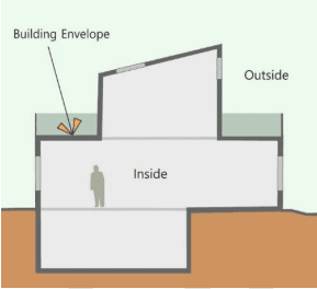
The exterior façade of the building including opaque elements and fenestrations is called the building envelope (Figure 4.1). Opaque elements include exterior walls, roof, slab on grade, basement walls and exterior doors. Fenestration systems include windows, skylights, ventilators, and doors that are more than one-half glazed.
Figure 4.1 Building Envelope
Building envelope provides a physical as well as a thermal barrier to the exteriors. The envelope itself does not use any energy directly but its design will determine the amount of heating and cooling required by building.
For example, an adequately shaded window bringing in good daylighting and blocking direct solar radiation will have two benefits – daylighting will reduce the need for electric lighting and shading will reduce the cooling requirement. Such design will eventually impact the energy use of the building. Hence, thermally efficient envelope is imperative to achieving energy efficiency.
Building heat transfer
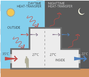
According to the second law of thermodynamics, heat flows from a hotter region to a cooler region until it reaches a state of equilibrium. In summer, during daytime, heat will flow from the cooler interiors to the warm exteriors. In winter, during night time, heat would most likely flow from warm interiors to the cold exteriors (Figure 4.2). This results in temperature fluctuations inside the building. Energy is used in countering these fluctuations to maintain a comfortable temperature inside the building. Understanding heat flow is fundamental to designing a good envelope to efficiency.
Figure 4.2 Heat transfer through building
Heat transfer across a building envelope takes place through conduction, convection and radiation.
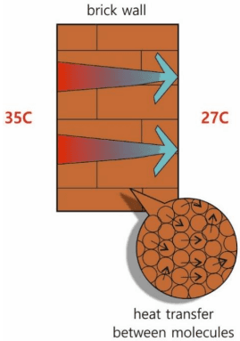
Conduction is the heat transfer through a solid medium due to temperature difference. There are two things required for conduction to take place – surface contact and temperature difference. For example, heat transfer across a 230mm brick wall will take place due to temperature difference across the wall (Figure 4.3). Heat will be transferred from one brick molecule to the other that are in contact.
Figure 4.3 Heat transfer through conduction
The rate of heat transfer is determined by the material property. Ideally, we want the building envelope to be a bad conductor of heat so that heat gains or losses can be minimized. This will result in a largely stable temperature inside the building which is desired for occupant comfort.
Convection is the heat transfer through a fluid medium such as air or water. Convection within the envelope assembly will depend on the temperature difference across the surfaces and also the air speed.
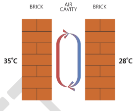
For example, heat transfer across an air gap within a wall will take place through convection (Figure 4.4). The heated exterior wall surface transfers heat to the air film on surface 2. Warm air becomes buoyant and starts moving and transferring heat to the cooler air molecules. Thus, warm air moves upwards and the cool air falls downward resulting in a cyclical movement within the wall cavity. This air movement within the cavity transfers heat from surface 2 to 3
through convection. This movement will continue until there is no temperature difference.
Figure 4.4 Heat transfer through convection
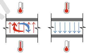
In a roof assembly, the air gap, if present, will be horizontal. Convection will take place similar like the wall. In Case 1 shown in Figure 4.5 the warm air is being formed at the bottom surface. It will become less-dense and start moving upwards while the cooler dense air will fall down forming a cyclical motion just like the wall cavity.
Figure 4.5 Convection in horizontal spaces
In Case 2, the warm air is being formed at the upper surface. Being less dense than the cooler air it will not move downwards and will become stagnant near the upper surface. In this scenario, convection will be negligible and heat transfer will take place by radiation in downward direction from the warmer surface to cooler one. Radiation is explained in the further sections.
Good design should minimize convection within the envelope assembly.
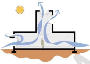
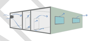
Convection also occurs within the building. In naturally ventilated buildings, convection occurs when outside air enters the buildings through openable fenestrations and either warms up or cools the interiors through air movement (Figure 4.6).
Figure 4.6 Convection through ventilation
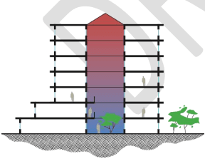
In tall spaces, warm air tends to rise and accumulate near the ceiling due to the same principle of buoyancy (Figure 4.7). This is called stratification which is a result of convection.
Figure 4.7 Stratification in atrium space
Exhausting the warm air from higher outlet will create a pressure difference to pull in cool air from the lower inlet. This is a forced convection strategy in passive building design to assist air
flow inside the building. In such cases, convection is desired to ensure air movement for comfort.
In a closed mechanically conditioned building, convection can take place by air entering or exiting through window cracks and other construction joints (Figure 4.8). When warm outside air enters the interiors, it adds heat to the space which eventually increases the cooling requirement. Similarly, when cold outside air enters the warm space in winters, it will increase the heating requirement. This is called infiltration which is desired to be minimized in energy efficient buildings.
Figure 4.8 Infiltration
Radiation is the heat transfer through electromagnetic radiation. All bodies facing an air space or a vacuum emit and absorb radiant energy continuously. Heat transfer by radiation will take place from a warmer surface to a cooler one. For example, if you are sitting close to a fire place, you feel warm because your body is gaining heat by radiation.
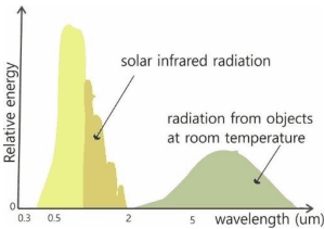
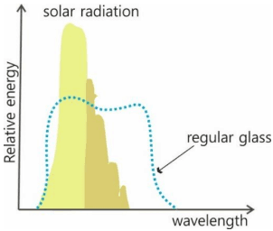
In the context of energy conservation, it is important to understand solar radiation and its impact on buildings. Solar radiation is an electromagnetic wave comprising of ultraviolet, visible and infrared radiation. The ‘solar infrared’ component has a short wavelength primarily due to its very high temperature.
Figure 4.9 Solar radiation spectrum
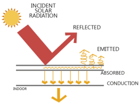
When the ‘solar infrared’ component comes in contact with earth or any object or a building, it transfers its energy to the object/building in the form of heat. This phenomenon is known as solar radiation heat transfer. This heat transfer from sun to other objects or surface is always in the form of shortwave infrared radiation.
interact differently with radiation.
When solar radiation is incident on the roof, the outer surface becomes warm and starts conducting heat through the material. When the inner surface becomes warm, it starts transferring heat as long wave radiation inside the room (Figure 4.9). Similarly, the outer surface of the roof starts losing heat through radiation to the atmosphere as long wave infrared radiation. This phenomenon is called thermal emittance.
Figure 4.10 Radiation heat transfer through roof
During nighttime, the process is reversed. The outside surface of the roof start radiating heat towards the cool night sky.
Radiation is affected by the surface property of the material. For example, light colored surface will absorb less heat compared to a dark colored surface consequently impacting the overall heat content of the material.
Transparent materials such as glass interacts very differently with solar radiation (short wavelength) than with long wave infrared radiation.
Figure 4.11 Glass and radiation
Glass is “selective” in what can pass through it. The high temperature short-wave solar radiation is able to pass right through a regular clear glass and ends inside the space as heat. As the objects inside the space get warmed, they start emitting radiation in the long-wave infrared spectrum. As shown in Figure 4.11, glass is opaque to the longwave infrared radiation and hence it traps a part of this energy and the room slowly heats up. This is called the greenhouse effect. This is the reason spaces enclosed by glass in a hot climate need increased air conditioning.
Material property that affect conduction:
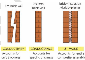
Conductance, denoted as c , is the ability of a material to encourage heat flow. Conductance is the number of Watts of heat that flow through a given thickness of a material when the temperature difference across the material is 1oC. Units are W / m 2 K. Sometimes, conductivity or the k value of the material could be given using which Conductance can be calculated. The conductivity of the material denotes the rate of heat transfer for a unit thickness when the temperature difference across the material is 1 ° C .
Example 4-A
Calculate conductance for 345mm brick wall. The k-value of fired brick with a density of 2 4 0 0 k g / m 3 is 1.21 W/m K.
Conductivity k = 1.21 W/m K
x = 3 4 5 mm = 0. 3 4 5 m
ConductanceC=k/x=1.21/0.345=3.5W/m2K
Thus, the conductance of 345mm brick wall is 3.5 W/m2 K
U-factor - In practice, a wall or roof assembly is usually a combination of more than one kind of material. For example, a brick wall can have plaster on the exterior and interior side or it could also have a granite cladding on the exterior and plaster on the interior. In such cases, the total conductance of the assembly should be calculated. This is called U-factor which is the overall coefficient of heat transfer. Units are W / m 2 K
Thus, U-value is the sum of conductance of each material of the assembly.
U = C ₁ + C ₂ + C ₃ + … … + C n
Thus, U = ΣC
Where,
C₁,C₂,Cn are the conductance of individual layers of the assembly.
Figure 4.12 Conductance and U-value
U-factor takes into account the conductance of each material of the assembly. It does not include the effect of moisture related heat flow. An example of how the U-value for an assembly can be calculated is shown in Example 4-B.
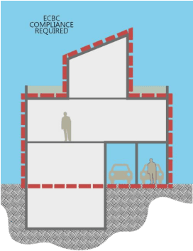
The ECBC specifies minimum U-value for roof and walls that are above grade.
Figure 4.13 ECBC scope of compliance
A GOOD ENVELOPE DESIGN WILL USE MATERIALS WITH LOWER U-FACTOR
Resistance, denoted as R i is the ability of a material to resist heat flow. It is the reciprocal of conductance. Units are m oK/W. The effectiveness of a material as an insulator is denoted by R-value. If the material thickness increases, the resistance also increases. When materials are placed in series, their thermal resistances are added so that the same area conducts lesser heat for a given temperature difference.
A Good Envelope Design Will Use Materials with Higher R-value
To calculate the R-value of an assembly, the individual resistances of each material should be calculated and a summation of these will give the final R-value as per the following formula.
Rt = Rsi + R₁ + R₂ + …… + Rn + Rse
Where,
Rt = Total thermal resistance of the assembly Rsi = Interior surface thermal resistance Rse = Exterior surface thermal resistance R1 , R 2 , R 1 1 are the thermal resistance of individual layers of the assembly.
U-factor is the reciprocal of R-value.
U=ΣR1
At exposed surfaces of solids, both on the exterior and interior, a thin film of air “attaches” itself to the surface offering some thermal resistance. This thin film of still air can offer resistance equivalent to that of a thickness of ½ inch or 12.7mm plywood (Grondzik, et al. 2009). When this air film gets disturbed, such as the case of wind blowing over the surface, its resistance drops down quickly and the air movement starts convecting heat, thus leading to heat transfer.
Table 4A Values of surface film resistance based on direction of heat flow
Rsi
Rse
Direction of heat flow
Direction of heat flow
Horizontal
Up
Down
Horizontal
Up
Down
0.13
0.10
0.17
0.04
0.04
0.04
R-value is especially useful when comparing insulation materials such as extruded polystyrene, rockwool and others.
Air spaces within the wall and roof construction add resistance to overall assembly and they need to be accounted for while calculating the Uvalue.
Table 4B Thermal resistances of unventilated layers between surfaces with high emittance
Thickness of air layer (mm)
Thermal Resistance (m2 .K/W)
Direction of Heat Flow
5710152550100300
Horizontal0.120.120.140.160.180.180.180.18
Up0.100.120.140.160.170.170.170.17
Down0.100.120.140.160.180.200.200.21
For ECBC compliance, the U-value of the roof and wall assembly need to be calculated. Sample calculations are shown in Example 4-B.
Example 4-B
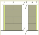
Calculate the U-value for the cavity wall construction shown below.
Layer 1 : 25mm cement plaster
Layer 2 : 230mm AAC wall
Layer 3 : 100mm air gap
Layer 4 : 115mm AAC wall
Layer 5 : 13mm cement plaster
Resistance for each layer can be calculated as follows
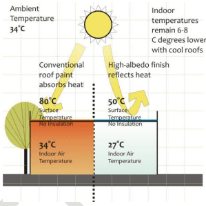
Radiation is affected by the surface of a material. The exterior finishes, be it paint or a kind of surface texture impacts the heat gain due to radiation. For example, shiny surfaces are able to reflect more heat than rough surfaces.
Figure 4.14 Material interaction with radiation
Reflectance is the ability of a material to reflect radiation without changing the temperature of tend to absorb less heat.
Solar reflectance is the ratio of solar energy that is reflected by a surface to the total incident solar radiation on that surface. Solar reflectance is measured on a scale from 0 to 1. A reflectance value of 0 indicates that the surface absorbs all incident solar radiation, and a value of 1 denotes a surface that reflects all incident solar radiation.
The term ‘albedo’ is often used inter-changeably with solar reflectance. High albedo or reflective surfaces stay much cooler than low albedo or less reflective surfaces.
Absorptance is the ability of a material to absorb radiation. This is converted into sensible heat within the material, thus raising its temperature. It is measured on a scale from 0 to 1. A value of 0 indicates that the surface reflects all incident solar radiation, and a value of 1 denotes a surface that absorbs all incident solar radiation. Thus, highly reflective surface will have very less absorptance.
ABSORPTION + REFLECTION = 1
Thus, radiation that does not get reflected, is absorbed.
Emittance is the ability of a material to re-radiate absorbed heat as invisible infrared radiation. It indicates the ability of a material to lose heat, consequently reducing the sensible heat content of the object.
Emittance, measured from 0 to 1, is defined relative to a black body with an emittance of 1. Some materials can emit more effectively than others. Polished metal surfaces have low emittances than most other materials.
Emittance and absorptance are not necessarily proportional, but they impact the sensible heat content in a material. Materials can absorb and emit at different wavelengths. For example, white paint absorbs 20% of the shortwave radiation from the sun and absorbs 80% of the long wave radiation from heated objects.
The emissivity of building material, unlike reflectance, is usually measured in the far infrared part of the spectrum.
A simple strategy like selecting the right color for external wall and roof can impact the heat radiation through radiation.
Table 4C Surface color and absorptivity
Category
Light
Medium
Dark
Black
Absorptivity Factor
<0.5
0.5 - 0.7
0.7-0.9
>0.9
Colors
White
Dark red
Brown
Black
cream
Light green
Dark green
Dark brown
Orange
Light blue
Vivid blue
Light red
Dark blue
Different surface finishes and their properties impact radiation heat gain are given in the following table.
Table 4D Material properties
Building Element Surface
Absorptance (solar radiation)
Emissivity (thermal radiation)
Lime sand stone, gray
0.60
0.96
Concrete, smooth
0.55
0.96
Brick facing, red
0.54
0.93
Aluminium, raw
0.2
0.05
Aluminium anodised
0.33
0.92
Plaster, white
0.21
0.97
Plaster, gray, blue
0.65
0.97
Glass
0.08
0.88
Paint, White
0.25
0.95
Building thermal loads
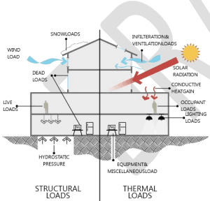
All buildings are subject to thermal loads. Just like a building is designed to meet the structural loads, it should also be designed to meet the thermal loads. Thermal loads depend on the climate, the building envelope and what is inside the building.
Figure 4.15 Analogy of thermal loads and structural loads
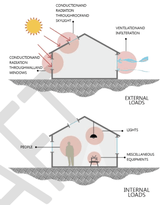
Thermal loads or heat loads denote the amount of cooling or heating required to provide occupant comfort. It is called heat loads because primarily, heat is either removed from the space
for cooling or added to the space for heating. Thus, heat loads are specifically referred to as cooling loads and heating loads.
Figure 4.16 Internal and external loads
It takes energy to either add heat to remove heat. Hence larger thermal loads will mean more energy used by the building to provide thermal comfort.
Climate plays a very important role in determining thermal loads. A building located in a hot and dry climate will need more cooling compared to a moderate climate. This is called external loads.
The envelope design must try to counter the external loads by proper thermal design of the walls, roof and fenestrations. The property of these materials will determine the heat gain from outside to inside. This is called envelope load. For example, a glass curtain wall will result in more heat gain as compared to 230mm brick wall of the same area. Thus, the envelope load of
a 80% glazed building is larger than a 30% glazed building with more opaque walls. If such a building was located in a hot-humid climate, then the cooling load for the 80% glazed building will be much larger than the 30% glazed building. Moreover, shading elements impact the heat gain as well.
People, lights and equipment inside a building add heat to the space. This is called internal loads. For example, the internal loads of a hotel will be larger than that of a school since there will be more lights, equipment and people on hotel. Except for the number of people using a building, all other aspects can be controlled by building design.
Thus, building design including the form, orientation, wall and roof construction, fenestration area, shading devices, surface finishes, lighting design, equipment efficiency, etc. plays a significant role in determining the thermal loads. The design process for sustainable and energy efficient buildings requires that such design decisions are taken during early stage design process.
The ECBC gives minimum requirements for building envelope to meet the thermal loads as per different climate.
BUILDING DESIGN WILL DETERMINE THE HEATING AND COOLING LOADS
Fenestration
Heat transfer across fenestration through conduction and convection is similar like walls and roof. Heat gain through direct solar radiation is unique to fenestrations which should be
understood clearly since it is a significant factor in determining the cooling loads of buildings.
The three criteria that determine the thermal performance of the fenestration are explained below:
U-factor
SHGC
VLT
4.2.1.1 U-factor
U-factors shall be determined for the overall fenestration product (including the sash and frame) in accordance with ISO-15099 by an accredited independent laboratory and labeled or certified by the manufacturer.
For Code compliance, the U-factor must account for the entire fenestration system including the effects of the frame, the spacers in the glazing.
In the U.S, the fenestration U-factors are determined in accordance with the National Fenestration Rating Council (NFRC) Standard 100. NFRC is a membership organization of window manufacturers, researchers, and other that develops, supports, and maintains fenestration rating and labeling procedures. Most fenestration manufacturers have their products rated and labeled through the NFRC program. Certified products receive an 8.5”x11” NFRC label that the enumerates the U-factor, SHGC and the VLT.
4.2.1.2Solar Heat Gain Coefficient
The ECBC requires that SHGC be determined in accordance with ISO-15099 by an accredited independent laboratory, and labeled and certified by the manufacturer. Designers should insist on getting SHGC data from manufacturers.
Shading Coefficient (SC) and SHGC
SHGC has replaced the term Shading Coefficient (SC) that was being used earlier to quantify the same concept.
Shading Coefficient specially addresses only the glass unit of the fenestration excluding the frame. SC is the ratio of radiant heat gain through a given type of glass relative to a 3mm thick clear glass.
Whereas, SHGC includes the effect of the entire fenestration assembly including the frame and the glass.
Exceptions to §4.2.1:
(a) If the SC value for glass is available, then compliance with this section can be shown by the following calculation. SHGC = SC x 0.86
(b) Rated fenestrations typically include the SHGC of the entire system including the frame and the glass. However, if SHGC of glass alone is available from the manufacturer, then it will be an acceptable alternate for compliance with the SHGC requirements for the overall fenestration product.
4.2.1.3Visual Light Transmittance
ECBC encourages the use of daylight in buildings.
Visual light transmittance (VLT) shall be determined for the fenestration product in accordance with ISO-15099 by an accredited independent laboratory, and labeled or certified by the manufacturer. For unrated products, use the default table in Appendix A.
Transmittance is a property characteristic of transparent element such as glass. Radiation transmits through such elements and ends up in the space as sensible heat. More about this property is discussed in detail in section
Light to Solar Gain ratio (LSG)
Sunlight brings in both light and heat. Daylight is desirable without the heat gain. Fenestration products should block heat but admit light.
The Light to Solar Gain ration (LSG) shows relationship between SHGC and VLT as follows:
LSG = SHGC / VLT
GLAZING WITH GREATER LSG ARE MORE SUITABLE FOR DAYLIGHTING IN HOT CLIMATES.
Opaque construction
U-factors shall be calculated for the opaque construction in accordance with ISO-6946. For unrated products, use the default tables in Appendix A.
Daylighting
Since the beginning of construction, daylight has been a big factor in the designs of buildings. Daylight is integral to good building design. Several studies have proven the benefits of daylighting, linking to higher comfort, productivity and feeling of well-being in buildings. An appropriately designed daylighting feature will provide better indoor environmental quality, improve building occupant performance and reduce the building’s energy consumption at the same time.
Daylighting can significantly impact the energy use of a building by reducing the lighting energy demand by up to 20-30%. ECBC 2017 mandates the provision of daylighting in buildings. This is a significant update in the Code. The requirement for daylighting will impact building geometry, glass selection, lighting and cooling energy use. This requirement could encourage architects to integrate passive design principles and hence climate appropriate design. Consequently, such a design will reduce the need for lighting and cooling in buildings.
Having good daylighting in a building requires the thought process to be initiated and integrated from the very beginning of the building design
process. Appropriate use of windows, skylights, clerestories, and other apertures in the building are the means to harvest daylight.
4.2.3.1Daylighting Simulation Method
Computer simulations help create a virtual model of the space for which daylight levels is to be predicted. One of the major benefits of using simulations is the ability to model the buildings and its surroundings exactly the way it is and hence get a realistic estimate of the daylight levels in the design. It is also helpful for the assessment of complex designs. Although executing simulations requires a specialized skill set, such analytical tools and design methods are growing in the industry.
Only BEE approved software shall be used to demonstrate compliance through the daylighting simulation method. A list of approved software for daylighting analysis from Appendix E: BEE approved list of software to show compliance is reproduced here for convenience.
The simulation method can be adopted for compliance towards §4.2.3 even if the project
has chosen the prescriptive approach for Code compliance.
Analysis
Software
Daylighting
AGI32 (Licaso)
Daysim
Design Builder
DIVA
Groundhog
IES-VE
OpenStudio
Radiance-Rhino-Grasshopper with
Daylighting Plugins
Sefaira
Sensor Placement + Optimization
Tool (SPOT)
The following points are to be incorporated while executing daylight simulations. As per the Code,
Illuminance levels for all spaces enclosed by permanent internal partitions (opaque, translucent, or transparent) with height greater or equal to 2m from the finished floor, shall be measured as follows:
(a) Measurements shall be taken at a work plane height of 0.8 m above the finished floor.
(b) The period of analysis shall be fixed for 8 hours per day, anytime between 8:00 AM IST to 5:00 PM IST, resulting in 2920 hours in
total for all building types except for schools. Schools shall be analyzed for 7 hours per day, anytime between 7:00 AM IST to 3:00 PM IST.
(c) Available useful daylight across a space shall be measured based on point-by-point grid values. UDI shall be calculated for at least one point for each square meter of floor area.
Goals of daylighting
The goals of a good daylighting design is to
Provide sufficient illuminance
• Minimize glare
Provide overall visual comfort
Result in improved aesthetics
Enhance occupant comfort, productivity and health
Reduce electric lighting energy usage
A well thought out design can easily achieve these goals.
Focus should be given to maximum daylight factor, increase uniformity of light spread, reduce glare, and minimize solar gains.
Spaces will high ceilings can accommodate taller windows that help pull daylight further into the space.
Plan for daylight by minimizing floor plate depth, especially in office buildings
SOUTH FACING SPACES WILL RECEIVE DAYLIGHT THROUGHOUT THE DAY AND MOST OF YEAR. HEAT GAIN CAN BE EFFECTIVELY CONTROLLED ON THE SOUTH FAÇADE.
Design strategies for daylighting
There are many design strategies for daylighting in buildings as explained below. These are also fundamental to the concept of solar passive design which means that buildings are designed in response to sun and climate. Such buildings are able to provide comfort using natural resources to a great extent and hence significantly reduce the need for air conditioning.
Building orientation and form
The orientation determines access to sun. Buildings can be located and oriented to take advantage of sun’s movement throughout the day, as well as seasonal variations.
Buildings that are longer on their east-west axis are better for daylighting and visual comfort.
Larger and taller buildings should have thinner profiles to maximize daylighting potential from side windows.
Large buildings can get daylight into more spaces by having central courtyards or atria, or having other cut-outs in the building form.
Fenestrations
Amount of daylight that enters a room depends on the window location and its dimensions.
Determine the window size, height and glazing treatments for each facade separately.
Maximize southern exposure and optimize northern exposure.
• North-facing windows provide consistent indirect light with minimal heat gains.
Minimize eastern and western exposure when the sun is lowest and most likely causes glare and overheating. They are more difficult to shade because the sun is closer to the horizon.
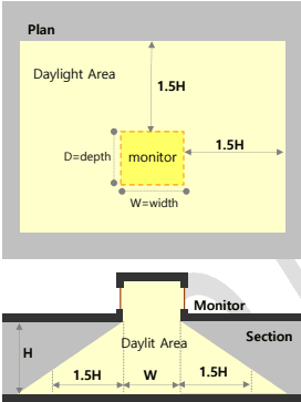
There is a direct relationship between the height of the window head and the depth of daylight (Typically adequate daylight will penetrate 1.5 times the height of the window head).
Windows located high in a wall or in roof monitors and clerestories will result in
deeper light penetration and reduces the likelihood of excessive brightness.
Use skylights and roof monitors to areas without easy access to windows.
Shading devices
Shading devices help bring in daylight without heat. Unlike artificial light fixtures, you can block heat from sunlight and still get light. The size and shape of the shading device is key to block direct solar radiation. Some shading strategies are enumerated below.
South-facing windows are the easiest to shade. Horizontal shading devices are most effective as they can block summer sun and admit winter sun.
East- and west-facing windows are best shaded with vertical devices, but these are usually harder to incorporate into a building, and limit views from the window.
The provision of glare protection devices will reduce the amount of daylight harvested. A balance between glare protection and daylight harvesting needs to be done carefully to ensure that the design of the daylight harvesting system will perform as intended.
BLOCK DIRECT SOLAR RADIATION USING RIGHT SIZE AND FORM OF SHADING DEVICES TO GET LIGHT WITHOUT HEAT
Other strategies
Design strategies can go beyond the building form and windows.
Use advanced daylight harvesting methods in case of large window area (such as use of external light shelves, light tubes, a higher ceiling height and other similar technologies, would help to distribute the daylight deeper into the building).
Use of light coloured interior surfaces coverage.
GOOD DAYLIGHTING DESIGN WILL AIM FOR UNIFORMLY DISTRIBUTED LIGHT LEVELS WITHOUT GLARE
BOX 4-1 : Design guidelines for daylighting
Buildings that are longer on their east-west axis are better for daylighting and visual comfort
Limit the depth of the floor plate to maximize daylit area. Daylight penetration is about 1.5 times the window head
taller windows help pull daylight further into the space.
Horizontal shading devices are most effective on south facing windows as they can block summer sun and admit winter sun.
Minimize windows on the east and west facade when the sun is lowest and most likely causes glare and overheating.
Use skylights where side lighting cannot be used for adequate lighting of the deeper areas of the floorplate.
North facing skylights are most suitable for work spaces
To reduce glare, skylights must be designed with reflective surfaces that redirects direct sunlight into the space.
Key metrics in daylighting
Illuminance: The amount of light falling on a surface is called illuminance.
This is a fundamental metric common to both daylighting and artificial lighting. Standards such as the NBC and ASHRAE 90.1 specify illuminance levels for various space types such as corridors, open office space, classroom and others. Good building design will try to meet the illuminance levels through daylighting. Illuminance can be measured by a lux meter. Units are lumens/sqm.
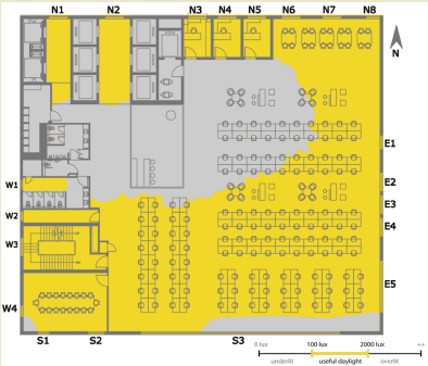
ECBC mandates that buildings shall achieve illuminance level between 100 lux and 2,000 lux for the minimum percentage of floor area for different building types as per §2.5.
Daylight Factor: Daylight levels keep changing throughout the day and the year since sky conditions are dynamic. Daylight Factor (DF) was
developed to estimate the illuminance inside a space with respect to the exterior illuminance assuming an uniform overcast sky.
Daylight Factor is a ratio of interior illuminance to exterior illuminance.
The National Building Code (NBC) specifies sky illuminance for different climate zones as per Table 4 E.
Table 4E Illuminance for climate zone
Climate Zone
Illuminance (lux)
Hot and humid
9000
Hot and dry
10500
Composite
8000
Cold and sunny
6800
Daylight Factor is a static metric to measure daylight since it considers overcast sky only. It continues to be used due to its simplicity.
However, Daylight Factor is limiting in terms of not considering the impact of building and window orientation, glazing specification and time of day. The drive towards sustainable and energy efficient buildings has led to the use of metrics that are more realistic and hence help taking important decisions during early design stage. Hence, ECBC has now included the metric - Useful Daylight Illuminance which is explained further.
Brightness: Human beings judge brightness of an object relative to the brightness of the surroundings. To a great extent, it depends on the adaptation of the eye. Brightness is a perception of the observer.
For example, car headlamps seem very bright at night but are just noticeable during the day. The brightness we perceive depends on the brightness of the headlamps relative to the overall lighting condition. The levels of brightness can result in useful contrast or discomfort glare as explained below.
Contrast: By definition, contrast is the difference between the brightness of an object and that of its immediate background. Contrast can be extremely helpful in visual task performance. Objects with high contrast are easier to see than objects with low contrast. For example, try to read the text below in Figure 4.17. The text against the lighter background is easier to read than the darker one.
Figure 4.17 Contrast
High contrast is the critical factor in visual appreciation of details such as outline,
silhouette, and size, etc which are the factors involved in tasks such as reading, writing.
Glare: Excessive contrast will reduce the visibility. This results in glare. An extremely bright object against a dark background causes discomfort and can interfere with our visual perception.
Direct glare is caused by a light source sufficiently bright to cause discomfort or loss in visibility. For example, in Figure 4.18, the bright sun shining right onto the street reduces direct visibility in the immediate surroundings.
Figure 4.18 Direct glare
Indirect glare is caused by reflections of light sources on glossy surfaces. An example is shown in Figure 4.18.
Figure 4.19 Indirect glare
Usually, buildings having very large glazed areas tend to have the problem of glare inside the space. Further, light reflected off the glass façade can result in glare on neighboring buildings and objects. Overall, glare is commonly associated with discomfort and hence undesirable.
Glare can be controlled by using external shading devices on fenestrations and/or by using interior blinds.
Useful Daylight Illuminance
Daylighting design does not mean abundance of light filling up a space, but it is a careful balance of light and heat. It is important to have useful daylight which is what the term ‘Useful Daylight Illuminance’(UDI) refers to.
UDI is defined as the annual occurrence of illuminances across the work plane that are within a range considered “useful” by occupants (Nabil and Mardaljevic 2005). UDI is an attempt to integrate glare and daylight levels in one scheme.
The UDI considers the range between 100 lux and 2,000 lux on the workplane as ‘useful daylight’. Above this threshold, daylight is not desired due to potential glare or overheating. Daylight levels below this range is considered inadequate for tasks. The workplane is considered as the horizontal plane at a height of 30 inches or 760mm. It is a common practice to assess illumination levels at the workplane level since most activities are considered to take place at this height.
There is limited research in support of considering 2,000 lux as an absolute upper threshold. However, UDI is a widely used metric in the industry and is considered more realistic in predicting daylight levels in space.
Above grade floor areas shall meet or exceed the useful daylight illuminance (UDI) area requirements listed in Table 4-1 for 90% of the potential daylit time in a year. Mixed-use buildings shall show compliance as per the criteria prescribed in §2.5. Compliance shall be demonstrated either through daylighting simulation method in §4.2.3.1 or the manual method in §4.2.3.2. Assembly buildings and other buildings where daylighting will interfere with the functions or processes of 50% (or more) of the building floor area, are exempted from meeting the requirements listed in Table 4-1.
A building should meet the following UDI parameters for ECBC compliance.
Meet the illuminance range of 100 – 2000 lux
Meeting UDI levels ranging from 10% to 40% of the gross floor area as per Table 4-1. The floor area requirement changes as per the building type and the targeted performance level.
UDI levels should meet 90% of the potential daylit time in a year. This means that the space/room receives useful daylight for 90% of the time.
Potential daylit time is considered as 8 hours per day anytime between 8am and 5pm for all building types except for schools which will be for 7 hours anytime between 7am and 3pm.
Table 4-1Daylight Requirement
Building Category
Percentage of requirement
above grade floor area meeting the UDI
ECBC
ECBC+
SuperECBC
Business,
40%
50%
60%
Educational
No Star Hotel
30%
40%
50%
Star Hotel
Healthcare
Resort
45%
55%
65%
Shopping Complex
10%
15%
20%
Assembly*
Exempted
*and other buildings where daylighting will interfere with the functions or processes of 50% (or more) of the building floor area
Daylight compliance
Compliance shall be demonstrated by either of the following two methods.
Simulation Method (§4.2.3.1)
Manual calculation method (§4.2.3.2)
(d) Fenestration shall be modelled with actual visible light transmission (VLT) as per the details provided in the material specification sheet.
(e) All surrounding natural or man-made daylight obstructions shall be modeled if the distance between the façade of the building (for which compliance is shown) and surrounding natural or man-made daylight obstructions is less than or equal to twice the height of the man-made or natural sunlight obstructers. Refer Figure 4.20.
Figure 4.20 Modeling surrounding obstructions
If the reflectance of the surfaces is not known, default reflectance of 30% and 0% shall be used for all vertical surfaces of manmade and natural obstructers respectively.
(f) Interior surface reflectance shall be modeled based on the actual material specification. If material specification is not available, following default values shall be used:
Table 4-2Default Values for Surface Reflectance
Surface Type
Reflectance
Wall or Vertical Internal Surfaces
50%
Ceiling
70%
Floor
20%
Furniture (permanent)
50%
Buildings shall achieve illuminance level between 100 lux and 2,000 lux for the minimum percentage of floor area prescribed in Table 4-1 for at least 90% of the potential daylit time.
4.2.3.2Manual Daylighting Compliance Method
This method can be used to show compliance through calculations without using computer software. Manual calculation is an easier approach compared to using simulations. However, it can be limiting in assessing the full potential of a building design. Generally, the manual method is suitable for projects adopting the prescriptive compliance approach.
Daylight extent factors (DEF) mentioned in Table 4-3 shall be used for manually calculating percentage of above grade floor area meeting the UDI requirement for 90% of the potential daylit time in a year.
The DEF accounts for orientation and glazing VLT of the fenestration, shading devices adjacent to it and building location. Thus, the building design parameters are taken into account in the manual method.
Steps for manual calculations are given below:
Determine the projection factor for every fenestration that has a shading device as per the following.
Figure 4.21 Projection Factor calculation
Projection factor, overhang: the ratio of the horizontal depth of the external shading projection to the sum of the height of the fenestration and the distance from the top
of the fenestration to the bottom of the farthest point of the external shading projection, in consistent units (Figure 4.21).
Projection factor, side fin: the ratio of the horizontal depth of the external shading projection to the distance from the window jamb to the farthest point of the external shading projection, in consistent units.
Projection Factor, overhang and side fin: average of ratio projection factor for overhang only and projection factor of side fin only.
Table 4-3Determine the Daylight Extent Factor (DEF) from Table 4-3 for each fenestration as per the orientation and corresponding VLT.
Table 4-3Daylight Extent Factors (DEF) for Manually Calculating Daylight Area
Shading
Latitude
Window Type
VLT < 0.3
VLT ≥0.3
North
South
East
West
North
South
East
West
No shading or PF <0.4
≥15°N
All window types
2.5
2.0
0.7
0.5
2.8
2.2
1.1
0.7
< 15°N
2.4
2.0
1.3
0.6
2.7
2.2
1.5
0.8
Shading with PF≥ 0.4
All latitudes
All window types without light shelf
2.8
2.3
1.5
1.1
3.0
2.5
1.8
1.5
Window with light shelf
3.0
2.5
1.8
1.6
3.5
3.0
2.1
1.8
3. Calculate the daylit area contributed by each fenestration as per the following
Vertical Fenestrations
I. In a direction perpendicular to the fenestration, multiply daylight extent factor (DEF) by the head height of the fenestration or till an opaque partition (with height greater or equal to 2m from the finished floor), whichever is less.
Daylit area (distance perpendicular to fenestration) = DEF * H
Figure 4.22 Daylit area calculation for vertical fenestration (section)
II. In the direction parallel to the fenestration, daylit area extends a horizontal dimension equal to the width of the fenestration plus either 1 meter on each side of the aperture, or the distance to an opaque partition of 2m high, or onehalf the distance to an adjacent fenestration, whichever is least.
Daylit area (distance parallel to fenestration) = W + 2m
Figure 4.23 Daylight area calculation for vertical fenestration (plan)
Skylights
III. For skylights, calculate the horizontal dimension in each direction equal to the top aperture dimension in that direction plus either the floor-to-ceiling height (H) for skylights, or 1.5 H for monitors, or H or
2H for the sawtooth configuration, or the distance to the nearest 1 meter or higher opaque partition, or one-half the distance to an adjacent skylight or vertical glazing, whichever is least.
Daylit area for skylight = W+ (H*2)
Figure 4.24 Daylit area calculation for skylight
Daylit area for sawtooth = H + W+ 2H
Figure 4.25 Daylit area calculation for sawtooth
Daylit area for monitor = W+ (1.5H*2)
Figure 4.26 Daylit area calculation for monitor
A summation of all the individual daylight areas should be done showing compliance as per Table 4-1.
An architectural plan shall be prepared with all daylit areas marked on the floor plans.
Glazed facades and fenestrations with non-cardinal orientation, shall be categorized under a particular cardinal direction if the orientation is within ± 45 degrees of that cardinal direction.
Any surrounding natural or man-made daylight obstructions shall not be considered in this method.
Daylit area overlap: For overlapping daylit areas such as windows on different orientations or in case of skylights the overlapping daylit area shall be subtracted from the sum of daylit area.
Documentation of the calculations:
A separate architectural plan shall be prepared with all daylit areas marked on the floor plans.
ii. A summary shall be provided showing compliance as per Table 4-1.
Example 4-C
An office building in Delhi is trying to achieve ECBC level compliance. Building is oriented along east west axis. The typical floor has a rectangular layout (33 m x 38 m) or 1,254 m2. VLT of glazing in all orientations is 0.39. Windows have light shelves and external shading devices with PF ≥ 0.4. Head height of fenestrations is 3.0 m. Length of glazing on the north and south facing façade is 45 meter and on the east façade, 25 meter. Determine if this building is compliant with ECBC.
As per compliance requirements listed in Table 4-1 the project should have a minimum of 40% of its floor area exposed to daylight in range of 100 – 2,000 lux for at least 90% of the year.
Thus, this project must have at least 502m2(40% of 1,254 m2) of floor area fulfilling the UDI requirements. Compliance with § 4.2.3 Daylight Requirements can be checked for through two approaches.
Simulation method
Manual calculation method
Simulation method
The image below, developed through an BEE approved software (§ 3.4), specifies the lux levels and time period of a year during which lighting levels would be available. With this information, designers can check if the required minimum area as per § 4.2.3 has the required daylight levels.
UDI Analysis with a Daylighting Analysis Software
Manual calculation method
Step 1: Since the projection factor and VLT are already given, list the DEF from
Table 4-3 for each orientation. Thus,
DEF for windows in North = 3.5
DEF for windows in South = 3.0
DEF for windows in East = 2.1
DEF for windows in West = 1.8
Step 2 : Calculate the daylit area for each fenestration. There are only vertical fenestrations in this building. Head height is 3.0 m.
Thus, for direction perpendicular to the fenestration, daylit area = DEF * 3m Thus, for direction parallel to the fenestration, daylit area = Window width + 2m
For overlapping daylit areas such as corner windows. Subtract the overlapping daylit area from the sum of daylit area.
UDI analysis with manual calculations
The calculation for each fenestration can be tabulated as follows. As per the calculations 616.5 m2 of floor area will meet the UDI requirements during 90% of the year. This is 49.2 % of the total above grade floor area of 1,254 m2. Thus, the building floor will comply with UDI requirement. Following Tables shows calculated Daylight Area Meeting UDI Requirement.
Table 4-1-1 Manual calculation for Daylight Area Meeting UDI Requirement
Orientation-NORTH, DEF-3.5, Fenestration Head Height H - 3m
Window without opaque obstructions
Fenestration Width W (m)
A= H x DEF (m)
B= L1+W+ L2 (m)L1= L2=1m
Area meeting the UDI requirements = AxB (m2)
N7
2.0
10.5
4.0
42.0
N6
2.0
10.5
4.0
42.0
N2
2.0
10.5
4.0
42.0
Window with opaque obstructions
Fenestration Width W (m)
A= Distance till parallel Obstruction (m)
B= L1+W+ L2 (m)L1= L2=Distance to perpendicular Obstructions
Area meeting the UDI requirements = AxB (m2)
N1
2.0
10.5
0.3+2+0.3=2.6
27.3
N3
2.0.
4.0
Building Envelope Sealing
Uncontrolled entry of air through the building envelope is called infiltration or air leakage. In air conditioned buildings, when warm air from outside enters the interiors, it adds sensible heat to the conditioned space. If the outside air is moist, it also adds latent heat. The air conditioning system has to work more to remove this additional heat which increases energy consumption. Hence energy efficient buildings should prevent infiltration.
Further, infiltration can cause condensation to form within and on walls. This can create many problems including reducing insulation R-value, permanently damaging insulation, and seriously degrading materials.
It can rot wood, corrode metals, stain brick or concrete surfaces, and in extreme cases cause concrete to break, bricks to separate, mortar to crumble and sections of a wall to fall jeopardizing the safety of occupants. It can corrode structural steel, re-bar, and metal hangars and bolts with very serious safety and maintenance consequences. Moisture accumulation in building materials can lead to the formation of mold that may require extensive remedying the situation.
Virtually anywhere in the building envelope where there is a joint, junction or opening, there is potential for infiltration. This will cause the HVAC system to run more often and longer at one time, and still leave the building uncomfortable for its occupants.
A tightly constructed building envelope is largely achieved through careful construction practices and attention to detail. All openings in the building envelope, including joints and other openings that are potential sources of air leakage, should be to be sealed to minimize air leakage. It means that all gaps between wall panels, around doors, and other construction joints must be well sealed. Ceiling joints, lighting fixtures, plumbing openings, doors, and windows should all be considered as potential sources of unnecessary energy loss due to air infiltration.
It must be noted that building sealing is more important in air-conditioned buildings. In naturally ventilated buildings, the concept of building ceiling and tight envelope runs counter to conventional and traditional wisdom.
ECBC identifies several areas in the building envelope where attention should be paid to infiltration control. These include:
a) Joints around fenestration, skylights, and door frames
b) Openings between walls and foundations, and between walls and roof, and wall panels
c) Openings at penetrations of utility services through roofs, walls, and floors
d) Site-built fenestration and doors
e) Building assemblies used as ducts or plenums
f) All other openings in the building envelope
g) Exhaust fans shall be fitted with a sealing device such as a self-closing damper
h) Operable fenestration should be constructed to eliminate air leakages from fenestration frame and shutter frame.
4.3Prescriptive Requirements
All envelope components can comply with the prescriptive requirements as described in this section.
Roof
The intensity of solar radiation is highest on a horizontal surface such as roof. Atleast 80% of the day time heat gain is through the roof. Hence, heat gain through roof is significant. Improving thermal performance of the roof helps reducing the cooling loads of the building.
As per the Code,
Roofs shall comply with the maximum assembly U-factors in Table 4-4 through Table 4-6. The roof insulation shall be applied externally as part of structural slab and not as a part of false ceiling.
Table 4-4Roof Assembly U-factor (W/m2.K) Requirements for ECBC Compliant Building
Composite
Hot and dry
Warm and humid
Temperate
Cold
All building types, except below
0.33
0.33
0.33
0.33
0.28
School <10,000 m<sup>2</sup>AGA
0.47
0.47
0.47
0.47
0.33
Hospitality > 10,000 m<sup>2</sup> AGA
0.20
0.20
0.20
0.20
0.20
Table 4-5Roof Assembly U-factor (W/m2.K) Requirements for ECBC+ Compliant Building
Composite
Hot and dry
Warm and humid
Temperate
Cold
Hospitality, Healthcare Assembly
0.20
0.20
0.20
0.20
0.20
Business Educational Shopping Complex
0.26
0.26
0.26
0.26
0.20
Table 4-6Roof Assembly U-factor (W/m2.K) Requirements for SuperECBC Building
Composite
Hot dry
and
Warm humid
and
Temperate
Cold
All buildings types 0.20
0.20
0.20
0.20
0.20
Insulation
Insulation materials help reduce heat gain substantially. It is recommended that insulation materials be installed according to the manufacturer’s recommendations and in a manner that will achieve the rated insulation Rvalue. Compressing the insulation reduces the effective R-value and the thermal performance of the construction assembly. Insulation gives the maximum benefit when installed correctly in the right position.
Substantial Contact
It is recommended that insulation be installed in a permanent manner and in substantial contact with the inside surface of the construction assembly. If the insulation does not entirely fill the cavity, the air gap should be on the outside surface. Maintaining substantial contact is particularly important (and problematic) for batt insulation installed between floor joists. Without proper support, gravity will cause the insulation to fall away from the floor surface, leaving an air gap above the insulation. Air currents will ultimately find their way to the gap, and when they do, the effectiveness of the insulation will be substantially reduced.
Insulation Above Suspended Ceilings
It is not good practice to install insulation directly over suspended ceilings with removable ceiling panels. This is because the insulation’s continuity is likely to be disturbed by maintenance workers. Also, suspended ceilings may not meet the ECBC’s infiltration requirements unless they are properly sealed. Compliance with this requirement could have a significant impact in some parts of the country, as it is common practice to install insulation over suspended ceilings.
0.4+2+0.4=2.8
11.2
N4
2.0
4.0
0.4+2+0.4=2.8
11.2
N5
2.0
4.0
0.4+2+0.4=2.8
11.2
N8
1.5
10.5
0+1.5+1.0=2.5
26.3
Daylit area meeting UDI requirement
213.2
Orientation-SOUTH, DEF-3, Fenestration Head Height H - 3m
Area meeting the UDI requirements = AxB (m<sup>2</sup>)
S1
1.2
6.2
1.0+1.2+1.0=3.3
20.1
S2
1.7
6.2
1.0+1.7+0.3=3.0
18.6
S3
21.0
9.0
1.0+21.0+1.0=24
216.0
Daylit area meeting
UDI requirement
254.7
Orientation-EAST, DEF-2.1, Fenestration Head Height H - 3m
Orientation-EAST, DEF-2.1, Fenestration Head Height H - 3m
Orientation-EAST, DEF-2.1, Fenestration Head Height H - 3m
Orientation-EAST, DEF-2.1, Fenestration Head Height H - 3m
Orientation-EAST, DEF-2.1, Fenestration Head Height H - 3m
Window without opaque obstructions
Fenestration Width W (m)
A= H x DEF (m)
B= L1+W+ L2(m)L1= L2=1m
Area meeting the UDI requirements = AxB (m2)
E1
1.5
6.3
1.0+1.5+1.0=3.5
22.1
E5
5.5
6.3
1.0+5.5+1.0=7.5
47.3
Adjacent fenestration less than two meter apart
Fenestration Width W (m)
A= H x DEF (m)
B= L1+W+ L2(m)L1, L2=one half of distance to adjacent fenestration
Area meeting the UDI requirements = AxB (m2)
E2
2
6.3
1.0+2.0+0.2=3.2
20.2
E3
2
6.3
0.2+2+0.2=2.4
15.1
E4
2
6.3
0.2+2+1=3.2
20.2
Daylit area meeting UDI requirement
Daylit area meeting UDI requirement
Daylit area meeting UDI requirement
Daylit area meeting UDI requirement
124.9
Orientation-WEST, DEF-1.8, Fenestration Head Height H - 3m
Window without opaque obstructions
Fenestration Width W (m)
A= H x DEF (m)
B= L1+W+ L2(m)L1= L2=1m
Area meeting the UDI requirements = AxB (m2)
W3
2.0
5.4
1.0+2.0+1.0=4.0
21.6
W4
1.4
5.4
1.0+1.2+1.0=3.2
17.3
Window with opaque obstructions in daylit area
Fenestration Width W (m)
A= H x DEF (m)
B= L1+W+ L2(m)L1= L2=Distance to perpendicular Obstructions
Area meeting the UDI requirements = AxB (m2)
W1
1.0
5.4
0.3+1+0.3=1.6
8.6
W2
1.0
5.4
0.3+1+0.3=1.6
8.6
Daylit area meeting UDI requirement
56.1
Overlapping area calculations
Window with overlap areas
Width (m)
Depth (m)
Area (m2)
N4 and S1
3.3
3.3
10.9
S3 and E5
3.3
6.5
21.5
Overlapping daylight area (b)
32.4
Total Daylit area
ORIENTATION
Daylit area (m2)
NORTH
213.2
SOUTH
254.7
EAST
124.9
WEST
56.1
Total daylight area (a)
648.9
Total Overlapping daylit area (b)
32.4
Total daylit area meeting UDI requirement during 90% of the year (a-b)
616.5
Daylight area should be indicated in floor plans submitted to code enforcement authorities.
Note:
Design guidelines on daylighting stated in NBC (Part 8: Building Services, Section 1: Lighting and Natural Ventilation, Subsection 4.2: Daylighting) should also be referred to achieve the ECBC, ECBC+, or SuperECBC requirement.