In a parallel circuit, two or more branches with loads are connected to the same point (Figure 7.12). Current gets distributed in each branch as per the load while the voltage across each load in different branches stays the same. Thus total current in the circuit is the sum of individual branch currents.
Unlike the series circuit, individual resistances in a parallel circuit diminish rather than add up to make the total. In a parallel circuit, total resistance is calculated as
Whereas, total current is calculated as
I t o t a l = I ₁ + I ₂
resistance are connected in parallel
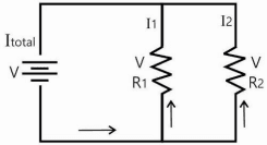
in effect, this parallel circuit is the same as two separate circuits combined into a single circuit shown below
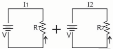
Figure 7.12 Parallel circuit arrangement
As shown in Figure 7.12, there are several closed circuits with a parallel arrangement. If the load R1 fails, the circuit will still be functioning. Parallel circuit is the standard practice in all building wiring. For example, in a room, the lighting will be on one circuit and the receptacles will be on another circuit. All of which will be connected to one junction box outside the room. There can be parallel circuit for lighting as well in
the same space which will ensure one circuit will be working if another circuit breaks.
IN A SERIES CIRCUIT: CURRENT THROUGH EACH COMPONENT IS SAME. CIRCUIT VOLTAGE IS THE SUM OF VOLTAGE ACROSS EACH COMPONENT. IN A PARALLEL CIRCUIT: VOLTAGE ACROSS EACH COMPONENT IS SAME. CIRCUIT CURRENT IS THE SUM OF INDIVIDUAL BRANCH.
Let’s look at an example to understand the circuit arrangement better. Figure 7.13 shows the electrical wiring for a typical classroom. Observe that the lighting and fans are on separate circuits. Some of the lights are connected in series. For example ‘Lighting series 1 ′ has two lights connected in series. All the individual series are connected to the same switch board. Thus, there are 4 parallel circuits for lighting. All fans are individually connected directly to the switchboard. This means, if one of the fans fails, the other will still be working. It is also possible to connect fans in series. But in this example, there are 9 parallel circuits for the fans which provides better user control.
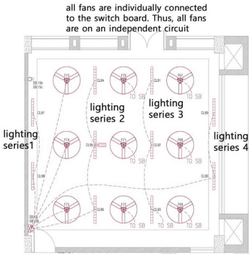
Figure 7.13 Sample electrical layout for a classroom
Building electrical system
The main components of the electrical system in a commercial building are shown in Figure 7.14. Fundamentally, there are two part to the entire electrical system – supply side and demand side.