Heat loss occurring in the transformer can cause increase in the temperature of the equipment. The insulation class of a transformer affects its permissible temperature rise and operating temperature,
and, as a direct result, its physical size, electrical power losses, overload capacity, and life.
7.2.1.1 Maximum Allowable Power Transformer Losses
Majority of the energy loss in the transformer occurs due to the heat generated in the core. To reduce these losses electrical distribution transformers are made of amorphous metal core which provides excellent opportunity to conserve energy right from installation. The amorphous material has unique physical and magnetic property that helps in reducing core loss of transformers. The efficiency of amorphous core transformer could reach up to 98.5% at 35% load. These transformers are costlier than conventional transformers. Conventional transformers are simple in construction but incur core losses are around 70% more than amorphous core transformers.
In distribution system, major losses occur due to long distance between the transformer and load. There will be frictional losses depending on the length and thickness of the electrical wire.
Hence, transformer is placed near the loads to reduce the length of wire and minimizing losses.
Transformer efficiency also depends on the operating load. Transformer losses consist of two parts: No-load Loss and Load Loss
No-load Loss (also called core loss) is the power consumed to sustain the magnetic field in the transformer's steel core. Core loss occurs whenever the transformer is energized; and it does not vary with load. Core losses are caused by two factors: hysteresis and eddy current losses. Hysteresis loss is that energy loss caused by reversing of the magnetic field in the core as the magnetizing alternating current rises and falls and reverses direction. Eddy current loss is a result of induced currents circulating in the core.
Load Loss (also called copper loss) is associated with full-load current flow in the transformer windings. Copper loss is power lost primary and secondary windings in the transformer due to the ohmic resistance of the windings. Copper loss varies with the square of the load current. (P=I2R). Transformer losses as a percentage of load is given in
By considering both the losses, total transformer losses can be computed with the help of following formula:
P TOTAL = P NO - LOAD + (% Load / 100) ² × P LOAD
% Load= (kVA Load/ Rated kVA)
As per the Code,
Power transformers of the proper ratings and design must be selected to satisfy the minimum acceptable efficiency at 50% and full load rating.
Permissible total loss values shall not exceed
(a) 5% of the maximum total loss values mentioned in IS 1180 for oil type transformers in voltage class above 11 kV but not more than 22 kV
(b) 7.5% of the maximum total loss values mentioned in above IS 1180 for oil type transformers in voltage class above 22 kV and up to and including 33 kV
(c) Dry type transformers should meet requirements as per IS code 1117
Figure 7.18.
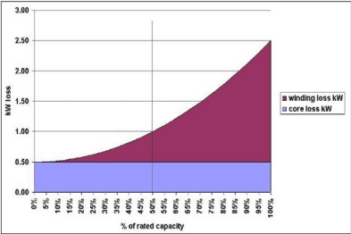
Figure 7.18 Transformer losses2
| Standard Ratings for Three Phase Dry Distribution Transformer upto and including 200 kVA (Clause xx) | ||
| S. No. | Nominal System Voltage | Standard Ratings (kVA) |
| (1) | (2) | (3) |
| i) | Up to and including 11 kV | *6.3,*10,16, *20, 25, *40,63, 100, 160 and 200 |
| ii) | Above 11 kV up to and including 22 kV | 63, 100, 160 and 200 |
| iii) | Above 22 kV up to and including 33 kV | 100, 160 and 200 |
| NOTE - * ratings are non-preferred | ||
| Standard Rating kVA (Clause xx) | s for Three Phase Dry Distribution Transfor | mer above 200 kVA upto and including 2500 |
|---|---|---|
| Sl No. | Nominal System Voltage | Standard Ratings (kVA) |
| (1) | (2) | (3) |
| i) | Up to and including 11 kV | 250, 315, 400, 500, 630, 1000, 1250, 1600,2000 and 2 00 |
| ii) | Above 11 kV up to and including 22 kV | 250, 315, 400, 500, 630, 1000, 1250, 1600,2000 and 2500 |
| iii) | Above 22 kV up to and including 33 kV | 250, 315, 400, 500, 630, 1000, 1250, 1600,2000 and 2500 |
| Standard Ratings for Single Phase Dry Type Transformer upto and including 25 kVA (Clause xx) | |
| Nominal System Voltage | Standard Ratings (kVA) |
| 11 kV | 5,10,16 & 25 |
| 22 kV | 10,16 & 25 |
| 33 kV | 16 & 25 |
Source: BEE
2 Energy Efficiency in Electrical Utilities, Bureau of Energy Efficiency, 2005.
| Rating (kVA) | Impedance (%) | Max. Total Loss (W) | |||||
| ECBC Building | ECBC+ Building | SuperECBC Building | |||||
| 50 % Load | 100% Load | 50 % Load | 100% Load | 50 % Load | 100% Load | ||
| 16 | 4.5 | 150 | 480 | 135 | 440 | 120 | 400 |
| 25 | 4.5 | 210 | 695 | 190 | 635 | 175 | 595 |
| 63 | 4.5 | 380 | 1250 | 340 | 1140 | 300 | 1050 |
| 100 | 4.5 | 520 | 1800 | 475 | 1650 | 435 | 1500 |
| 160 | 4.5 | 770 | 2200 | 670 | 1950 | 570 | 1700 |
| 200 | 4.5 | 890 | 2700 | 780 | 2300 | 670 | 2100 |
| 250 | 4.5 | 1050 | 3150 | 980 | 2930 | 920 | 2700 |
| 315 | 4.5 | 1100 | 3275 | 1025 | 3100 | 955 | 2750 |
| 400 | 4.5 | 1300 | 3875 | 1225 | 3450 | 1150 | 3330 |
| 500 | 4.5 | 1600 | 4750 | 1510 | 4300 | 1430 | 4100 |
| 630 | 4.5 | 2000 | 5855 | 1860 | 5300 | 1745 | 4850 |
| 1000 | 5 | 3000 | 9000 | 2790 | 7700 | 2620 | 7000 |
| 1250 | 5 | 3600 | 10750 | 3300 | 9200 | 3220 | 8400 |
| 1600 | 6.25 | 4500 | 13500 | 4200 | 11800 | 3970 | 11300 |
| 2000 | 6.25 | 5400 | 17000 | 5050 | |||
Total loss values given in above table are applicable for thermal classes E, B and F and have component of load loss at reference temperature according to Clause 17 of IS 1180 i.e., average winding temperature rise as given in Column 2 of Table 8.2 plus 300C. An increase of 7% on total for thermal class H is allowed.