Part 3Low-voltage Electrical Installations — Requirements for Special Installations or Locations
This Part 3 of the code covers the requirements for electrical installations for special purposes and at special locations. It can also be classified as electrical installations in non-industrial buildings. The requirements for electrical installations in industrial buildings has been detailed in Part 4 of the code. While a majority of installations could be categorically classified as non- industrial, an industrial complex would necessarily incorporate sub-units such as offices, residential quarters and support services which are either housed or fall in the category of non-industrial buildings. The requirement stipulated in Part 3 and Part 4 of this Code would therefore require judicious application.
With the current trend in power utilization, it would also be extremely difficult to classify electrical installations based on power requirement or the voltage of supply, as large buildings for non-industrial purposes consume sufficient power to consider them at par with the consumption of light industrial establishments. It is therefore necessary to consider for initial assessment of the installation the guidelines given in Part 1/Sec 8 this Code, which are better defined than the earlier terminology used for classifying installations. Also, this part specifies the requirements for installations in certain special purposes like supplies for electrical vehicles and furniture that require special attention for safety and ease of usability.
Part 3 of this Code, therefore covers requirements for several types of special applications and non-industrial occupations. In case of typical occupancies that strictly fall into any of these, recourse shall be made to the general guidelines stipulated in Part 1.
This Part consists of the following Sections:
Section 1 Domestic dwellings
Section 2 Locations containing a bath or shower
Section 3 Swimming pools and fountains
Section 4 Rooms and cabins containing sauna heaters
Section 5 Construction and demolition site installations
Section 6 Conducting locations with restricted movement
Section 7 Caravan parks, camping parks and similar locations
Section 14 Electrical installations in caravans and motor caravans
Section 15 Supplies for electric vehicles
Section 16 Operating or maintenance gangways
Section 17 Temporary electrical installations for structures, amusement devices and booths at fairgrounds, amusement parks and circuses
Section 18 Heating cables and embedded heating systems
Section 19 Office building, shopping and commercial centres and institutions
Section 20 Hotels
Section 21 Sports buildings
Section 22 Specific requirements for electrical installations in multistoried buildings
Domestic Dwellings
This section will give guidelines particularly in respect of Electrical Installations in Domestic Dwellings. The portion in this section shall be read with Part 1 Section 9 Wiring Installations. The recommendations given here under are to call for specific attention primarily to provide safe electrical environment from the point of view of users having no age band, who are uninstructed, with whom one cannot expect to have any technical knowledge and capability to identify possible electrical threats/hazards. Another point to consider is designing layouts, selecting fittings in respect of lighting, ventilation, power outlets to suite needs of such users at home; not for any particular period of day like office hours but for round the clock, which will provide comfort, ease of operation and convenience.
2References
2.1 Statutory Provisions
Section 53 of Electricity Act, 2003 dealing with ‘Protecting Public from Dangers of Electricity’.
Central Electricity Authority (Measures related to Safety and Electric Supply) Regulations, 2010, with further amendments.
2.2 Standards
IS No.
4648 : 1968 Electrical layouts in residential buildings
3646 (Part 2) : 1966 Code of practice for interior illumination
15707 : 2006 Testing evaluation installation and maintenance of a.c. electricity meters
8061 : 1976 Code of practice for design, installation and maintenance of service lines up to and including 650 V
SP 7 : 2016 National Building Code
SP 72 : 2010 National Lighting Code
3Terminology
For the purpose of this section, the definitions given in Part 1/Sec 2 and Part1/Sec 9 of this Code shall apply.
4 GENERAL AND COMMON ASPECTS OF ARCHITECTURAL DESIGN, PLANNING AND CIVIL CONSTRUCTION WORK FROM THE PERSPECTIVE OF ELECTRICAL INSTALLATIONS AND CHARACTERISTICS
4.1 Civil and Architectural Aspects
The objective of this section is to highlight needs of required base of infrastructure, related to architectural and civil planning and coordination. To consider electrical needs, appointment of electrical consultant/contractor is necessary from planning stage, so that question of incorrigible mistakes will not arise. The important points to be considered are given below;
a) Routes and service entry points;
b) Electrical meter rooms;
SP 30 : 2023
c) Shafts/ducts;
d) Interior design;
e) Aesthetics and electrical safety;
f) Ceiling fans
g) Exhaust fans;
h) Fire rating;
j) Wall thickness;
k) Water leakages/seepages;
m) Bathrooms/washrooms; and
n) Earthing.
For details 4 of Part 1/Sec 9, shall be referred.
4.2 Environment
The following environmental factors shall apply to electrical installations in domestic dwellings:
Environment
Characteristics
Remarks
(1)
(2)
(3)
Presence of water
Probability of presence of water is negligible
-
Presence of foreign solid bodies
The quantity or nature of dust or foreign solid bodies is not significant
-
Presence of corrosive or polluting substances
The quantity and nature of corrosive or polluting substances is not significant
Applicable for most of the locations except for dwellings situated by sea or in industrial zone in which case categorization AF2 applies (see Part 1/Sec 8)
Mechanical stresses
Impact and vibration of low severity
Household and similar conditions
Seismic effect and lighting
Depends on the location of the building
4.3 Utilization
The following aspects utilization shall apply:
Utilization
Characteristics
Remarks
(1)
(2)
(3)
Capability of persons
Uninstructed persons
Applies to all domestic installations
Contact of persons
Persons in normally situations
Conditions of evacuation during emergency
Low density occupation, easy conditions of evacuation
Buildings of normal or low height used for one or two family dwellings
Low density occupation, difficult conditions of evacuation
Apartment houses including high-rise flats
Nature of processed of stored material
No significant risks
5Electrical Design, Installation
5.1 General
Electrical design, layouts and installation shall be done keeping following points in mind on the basis of priority.
a) Safety;
b) Functionality;
c) Ease of operation; and
d) Aesthetics.
While designing layouts sustainability under respective environment, situation from the point of view of domestic installations is important, e.g. distance/clearing to be maintained between heat generating appliances in kitchen. Another point is requirements of user and perspective of architect in respect of electrical fixtures and appliances. Electrical consultant or contractor has to provide wiring installation to suit these requirements within the framework of codes and safety norms, hence role of electrical contractor/consultant begins from initial planning stage.
5.2Electrical Contractor, Consultant
5.2.1 Appointment
To avoid conflicts between electrical and civil work, aesthetics and electrical safety norms, ascertain related provisions of spaces, constructional requirements, avoid last time corrective measures/adjustments (which sometimes may turn out to be impossible to correct), appointment of chartered electrical safety engineer/licensed electrical contractor is necessary from initial stage. Under the circumstances of any conflict between civil and electrical work, it shall be seen that the problem gets resolved under mutual agreement without compromising safety.
5.2.2 Flawless Design
User/occupant being uninstructed person and not expected to have technical knowledge, is not allowed by law to interfere with electrical installation. Under urgency and in absence/unavailability of electrician user shall not attempt to resolve problem. This situation may arise due to frequent trouble arising out of defective installation. Therefore, it is important point to have sufficient experience specific to such type of installations to the electrical designer/consultant, so that the electrical installation will be safe and trouble free.
5.3 Wiring Systems
Wiring systems have been given under 5.3 of Part 1/Sec 9. Broadly wiring may either be surface type or concealed. Point to note here is in surface wiring it is easy to make and accommodate after thought changes. In case of concealed type wiring since the subsequent changes are difficult, involve breakages, likely to contradict predetermined values of load on circuits; prior decision or anticipations in respect of interior layout is very important.
5.4Material and Selection
Material shall conform IS specifications and certified accordingly. Selected material shall be sustainable under the situation and possible external influences as mentioned under 5.4 of Part 1/Sec 9.
5.4.1 Cables
It is recommended to use FRLSH/HFFR grade copper cables for internal wiring installation. Size of wires shall be selected correlating to current carrying capacity as per situation (see 5.5 of Part 1/Sec 9) and shall not be less than that recommended under Table 1. The current carrying capacity shall be net after considering all de-rating factors, for example, maximum allowable voltage drop (see 5.7 of Part 1/Sec 9).
NOTES
1 It shall be noted that there is vast difference in current carrying capacity of conductor of same size, depending situation, reference method of installation (see 5.5.2 of Part 1/Sec 9); which may reduce the capacity to 50 percent. So size shall be carefully selected.
2 Class 1/2 conductor shall preferably be used for fixed wirings.
5.4.2 Wire Enclosures - conduits/Trunking
For surface type wiring, conduits or trunking (also known as casing and capping) may be used. However, trunking shall not be used where it is likely to be get concealed including areas above false ceiling. For concealed wiring selection of metal/non-metal PVC conduits shall be made depending on situation. PVC trunking or conduits shall be FR grade and conduits shall have High Mechanical Strength (HMS) or at least Medium Mechanical Strength
(MMS). Metal conduits shall be selected where mechanical damages are likely to occur, for example, places may to get infected with rodents like voids/areas above false ceiling. Size shall be so selected that after drawing of wires 50 percent area will remain free. (for details see clause 5.9 from Part 1/Sec 9).
5.4.3 Accessories and Boxes
There is wide scope to select accessories to suite aesthetic needs. But selection shall be done considering sustainability under respective environment and class of user. Delicate, press-fit type accessories may not survive under rough use. Boxes may be metallic or non-metallic for metal conduits preference shall be given to metal boxes. Non-metal boxes shall be FR grade. Plug sockets if positioned below 1.2 m from floor level, shall be shuttered type only.
5.4.4 Fittings/Fixtures/Appliances
Lighting fixtures shall be capable to give desired lumen output, suite functional requirements and human comfort in respect of CCT, CRI and glair index. Preference shall be given to BEE star rated fittings. Heat dissipation factor shall also be considered with respect to location/base on which fitting is to be installed.
5.5Installation
5.5.1 Wire Enclosures and Routing
Routing of conduits/trunking shall be near and parallel to the edges of wall. Considering single phase distribution, separate enclosure shall be used for each phase (in case of three phase supply). Also, other wire enclosures of extra low voltage systems, for example, telephone, data, sound system, CCTV, control cables of automation, shall be separate with adequate spacing in between. In kitchens, from the point of view of safety, routes shall not conflict with gas pipelines/heat generating devices.
NOTE — For concealed type wiring work must be planned and coordinated with the activities of civil work.
5.5.2 Switch-boards
Followings points shall be noted in respect of switch-boards for general lighting, switch-boards for power outlets, and special purpose switch-boards.
NOTE — Locations of switch-boards have been recommended in general, however additional safety and accessibility must be considered from the point of view of children and disabled persons.
5.5.2.1 Switch boards-lighting
Location of general light and fan switch boards shall be positioned close to door frame and on opposite side of hinged edge of door, so that a person while entering can have immediate access to switch board. If a room has two doors; lighting control shall be provided on switch boards located near both doors. For the purpose use of two way switches may be made. General height shall be reachable and 1.2 m above ground level.
NOTE — It is recommended to provide a onboard 6A plug socket outlet on every lighting switchboard which insures availability of neutral and earth, which is required when additional board/extension is needed in future, which is possible if within limit of allowable loadcpoints on that circuit.
5.5.2.2 Switch boards – power outlets
Plug outlet boards for shall be located as near as possible from the position/proposed/anticipated location of appliance to avoid mess of loose hanging/suspended cords. If position of switch-board is above top of table/platform; it shall be 150 mm above the surface of table/platform top. Plug outlets if required at lower level shall be 200 mm above finished floor level and such plug sockets must be shuttered type. For wall mounted a.c. units suitable height may be above lintel level.
5.5.2.3 Switch boards – specific to utility area
Following additional points may be considered in respect of switchboard installation depending use of room/area.
a) Hall/living room — Additional switchboard may be provided adjacent to and accessible from sitting location for particular light/fan/plug outlet/charging point.
b) Kitchen — Location of power outlets shall be above working platform adjacent to the actual/anticipated position of appliance and shall not be behind the appliance. Special care shall be taken in respect of heat generating devices to maintain safe distance.
c) Bedrooms — Switchboards with two way controls for light fan shall be provided adjacent to bed location but not behind head position and shall be accessible from both ends of double bed. There shall be points for night
lamp/path light, reading lights and plug outlet for mobile phone/laptop charging. A switchboard shall also be provided near dressing mirror for light and plug outlets portable appliances like hair dryer.
d) Passages/staircase — Location shall be at entry/start point. Switchboards with two way control may be provided at both ends depending on distance/convenience.
e) Terrace/balcony — If sitting arrangement is considered plug outlets shall be provided adjacent to sitting area. Considering location of festive lamps/decoration, provisions of plug outlets at suitable location but safe from weather effects shall be made.
f) Wet areas - bathrooms/toilets — Boards shall be located away from area where there are chances of splashing of water. Preference shall be given to provide a switchboard immediate outside the door so that switch can be operated before entering and at the time of leaving, considering difficultly in locating switchboard in dark. Switchboard for mirror light above washbasin and plug outlet for appliance like electric razor shall be adjacent to mirror.
5.5.3 Distribution
Proper distribution is the basis of safe and trouble free electrical installation. Following guidelines will help to design the distribution.
5.5.3.1 Circuits for lighting load
Lighting load comprising lights, fans, 6A plug on boards shall be separated from power load. There shall be an independent lighting circuit for:
a) Each room, access of which is controlled by door (attached balcony/terrace may be included within the circuit of room);
b) Common areas, for example, passages, verandah;
c) Toilets; and
d) External lighting.
NOTE — Maximum points on any lighting circuit shall not exceed 24 or load shall not exceed 1 000 W. Provision of separate circuit shall be done if the load exceeds. Refer 5.6 for consideration of load.
5.5.3.2 Circuits for power load
There shall be independent circuit for:
a) Air-conditioner;
b) Water heater;
c) Oven/cooking range having load 2k W or above;
d) Washing machine/dishwasher having load 2k W or above; and
e) EV charging.
Maximum points of 16A shall not exceed 2 or load shall not exceed 3000 W on each circuit. Provision of separate circuit shall be done if the load exceeds.
5.5.3.3 Circuits for Inverter/UPS used as standby electrical supply
There shall be a separate circuit(s) comprising phase and neutral for the points to be provided on the supply from Inverter/UPS. Depending on load provision of separate DB may be necessary. Colour coding of such wires shall be brown/grey to identify the circuits easily. Neutral of such circuits shall not be looped anywhere with the points/circuits having no backup of inverter/UPS supply.
5.5.3.4 Cables-size
In domestic dwellings there are more occasions requiring additions and alterations in existing wiring installation due to purchases of new gadgets, changes in interior layouts. This may involve extra loading on the cables. Anticipating this aspect, it is desirable to consider one size higher for cables. For guidance, following table may be referred for considering minimum cross section of conductor.
SP 30 : 2023
Table 1Recommended Minimum Nominal Cross-sectional Areas of Conductor (Clause 5.4.1)
Use
Size (2 + E) copper
Point wiring for light/fan/bell/independent plug 6A
1.5 mm<sup>2</sup>
Branch circuit (DB to switch board) limited to total 10 points/800W
5.5.4 Point Wiring-lighting
5.5.4.1 Recommended values of illumination
Table 2 gives recommended values of illumination level. For further details refer SP 72 National Lighting Code.
5.5.4.2 Recommended points
Table 3 below shows recommended points on the basis of minimum functional requirement related to use and utility of the area. Actual requirement may vary to higher side.
Table 2Recommended Levels of Illumination for Different Parts of Domestic Dwellings (Clause 5.5.4.1)
Sl No.
Location
Illumination Level lux
(1)
(2)
(3)
i)
Entrances, hallways
100
ii)
Living room
300
iii)
Dining room
150
iv)
Bedroom: a) General b) Dressing tables, bed heads
300200
v)
Games or recreation room
100
vi)
Table games
300
vii)
Kitchen
200
viii)
Kitchen sink
300
ix)
Laundry
200
x)
Bathroom
100
xi)
Bathroom mirror
300
xii)
Sewing
700
xiii)
Workshop
200
xiv)
Stairs
100
xv)
Garage
70
xvi)
Study
300
413
Table 3Minimum Recommended Points as per Functional Requirement (Clause 5.5.4.2)
Portion of Dwelling Unit
Light Point Per 10-12 m<sup>2</sup> or Part
Fan/ex Fan Point Per 10-12 m<sup>2</sup> or Part
Bell Point Cable TV Telephone
Hall/Living room
2
1
1 1*
kitchen/dining
2
1 + 1
Bed room
4
5.5.5 Points – power Outlets 6A/16A/25A
With the increasing use of domestic gadgets sufficient number of power points shall be provided considering future requirement. This provision at initial stage helps proper sizing of cables and protections, which at later stage often raise problems of undesirable overloading to which existing wiring installation is not designed.
Table 4Recommended Power Outlets Depending on Anticipated Use of Appliance (Clause 5.5.5)
Portion of Dwelling Unit
6A Power Outlet Per 10-12 m² Or Part
6/16A Power Outlet Per 10-12 m² or Part
20/25 A Power Outlet
Hall/Living room
6a
1b
kitchen/dining
2c
4d
Bed room
6e
1f
1g
bath/toilet
1h
1i
passage/verandah
1j
balcony/terrace
1j
Entrance
1j
servant room/garage
2j
1j
Dry balcony or available space
1k
a TV, set top box, music system/DVD, mobile charging, movable/portable gadgets
b General purpose, vacuum cleaner, room heater
c Water purifier, general purpose- small mixer
d Fridge, microwave/OTG, induction, mixer/grinder
e Two bedside tables, TV, Set top box, computer, printer
f General purpose- room heater
g A.C.
h General purpose-shaver/drier
i Water heater
j Festive lighting/general purpose
5.6Load Consideration
For electrical design consideration of total connected load and diversity is important. Load can either be decided as custom requirement or anticipated/assessed general requirement.
5.6.1 For custom requirements tables 5 and 6 may be used to consider load depending on point of utility.
Table 5 Determination of Load of Lighting Points(Clause 5.6.1)
Connected Device on the Outlet of Point Wiring
Load Consideration
Light point*
50 W
Fan point
75 W
Power outlet 6A
100 W
NOTES
1* Light point may be utilized for a conventional incandescent lamp/tube light with ballast or single/group of LED lighting fixtures.
2 Fan shall include all types/sweeps/exhaust.
3 If actual rating of appliance is known, it may be taken into consideration subject to envisaged changes.
Table 6Determination of Load on Power Points (Clause 5.6.1)
Commonly Connected Devices on the Outlet of Power Point
Load Consideration in W
Bathroom
Storage type water heater
2000
Instant hot water geyser
3000
Dry balcony
Washing Machine
2000
Dish washer
1500
Kitchen
Electric Hot Plate
2000
Induction hot plate
2000
Electric oven
2000
Microwave
2000
Mixer/grinder
500
Fridge
500
Toaster/kettle
800
Air fryer
1500
Kitchen exhaust hood
350
Other
A.C 1TR/1.5 TR/2 TR
1250/1500/2000
Room heater
1000
Computer
150
TV
100
Iron
800
5.6.2 When there is no custom requirement, load may be considered on the basis of watts per m2 of carpet area. For design purpose load for domestic dwellings may be considered as 75W/m2.
NOTE — Sometimes Supply Company may set parameters to consider load per unit area, while sanctioning. Under the circumstances higher value shall be considered.
5.7 Earthing
5.7.1 Important extracts of Mandatory Provisions under CEA Regulations :
Regulation 16
‘the supplier shall be provide and maintain on the consumer’s premises for the consumer’s use, a suitable earthed terminal in accessible position at or near the point of commencement of supply’.
Further proviso states:
‘provided that in case of installation of voltages exceeding 250 V the consumer shall, in addition to the afore mentioned earthing arrangement, provide his own earthing system with an independent electrode.’
Regulation 41
(x) no person shall make connection with earth by the aid of, nor shall he keep it.in contact with, any watermains not belonging to him except with the consent of the owner thereof and of the Electrical Inspector.
(xiv) all metal casing or metallic coverings containing or protecting any electric supply line or apparatus shall be connected with earth and shall be so joined and connected across all junction and other openings as to make good mechanical and electrical connection throughout their whole length:
Provided that conditions mentioned in this regulation shall not apply, where the supply voltage does not exceed 250 V and the apparatus consists of wall tubes or brackets, electroliers, switches, ceiling fans or other fittings, other than ,portable hand lamps and portable and transportable apparatus, unless provided with earth terminal and to class-II apparatus and appliances.
Provided further that where the supply voltage is not exceeding 250 V and, where the installations are either new or renovated, all plug sockets shall be of the three pin type, and the third pin shall be permanently and efficiently earthed.
415
Without prejudice to the above mandatory provision Owner shall get it verified periodically from the electrical agency that:
a) Connections with water or any other metallic line shall not be opted as earth connection.
b) All electrical appliances, fittings provided with earth terminal/3 pin plug are properly connected with earth.
c) Earthing is in good condition. And, wherever consumer has his/her own earth electrode it shall properly maintained and tested at least once in a year during summer value of which shall not exceed 2 ohms.
d) Under the multiple neutral earthing system, if suppliers neutral is earthed in consumer’s premises, consumer’s earth electrode shall maintain distance of at least 3 m. In case of multiple consumers, Earth Bus shall be of adequate capacity to which individual consumer’s earth conductor is connected. Such connections must be done with properly crimped lug duly tightened with nut bolt. Since copper conductor is recommended for wiring installations in domestic dwellings, preference may be given to copper earth electrode and bus to avoid contact related issues between different metals. Under unavoidable conditions bimetallic lug shall be used.
5.8 Fans, Light fittings, Appliances
5.8.1 Fans
Provision of ceiling, exhaust and other fans shall be done in accordance with 9.2 of Part 1/Sec 9 of this code.
5.8.2 Lighting Fixtures
Provision of lighting fixtures shall be done in accordance with 9.1 of Part 1/Sec 9 of this code. Recommended illumination level may also be referred from IS 4648.
5.8.3 Fixed and Portable Appliances
For appliances other than class II, proper connectivity to earth shall be checked. Connections shall be through shielded cord only. Heat generating appliances/parts shall be safely located and shall be provided with suitable thermostat.
5.9Service Connections, Meters
Safety issues and maintenance of electrical service line, meter, switchgears, etc; at the point of supply/in meter room are the matters of individual as well as joint concerns of owner of dwelling and supplier of electricity. Following points shall be noted in this regard.
5.9.1 Electrical Meter Rooms
Meter rooms shall be separate. It shall be planned to have sufficient head room and clear space in front of meters, control switches (at least 1m). Space on wall shall be sufficient to accommodate required number of meters at such height that readings can be taken without aid of any tackle. Also the switchgears shall be at least 0.5 m above floor level and within such height to have an easy access for operation. The meter room shall be well ventilated, protected from external influences like sun, rain, water seepages, entry of rodents. Location of meter room shall be suitably adjacent or nearest to cable duct/shaft/vertical route of mains.
5.9.2 Supplier’s Obligations
Regulation 13 and 14 of CEA Regulations gives mandate in respect of responsibilities of supplier and consumer as below:
‘13(1) The supplier shall ensure that all electric supply lines, wires, fittings and apparatus belonging to him or under his control, which are on a consumer’s premises, are in a safe-condition and in all respects fit for supplying electricity and the supplier shall take precautions to avoid danger arising on such premises from such supply lines, wires, fittings and apparatus’.
‘13(2) Service lines placed by the supplier on the premises of a consumer which are underground or which are accessible shall be so insulated and protected by the supplier as to be secured under all ordinary conditions against electrical, mechanical, chemical or other injury to the insulation,
14, Switchgear on consumer’s premises.- (1) The supplier shall provide a suitable switchgear in each conductor of every service line other than an earthed or earthed\ neutral conductor or the earthed external conductor of a concentric cable within a\ consumer’s premises, in an accessible position and such switchgear shall be contained within an adequately enclosed fire-proof receptacle:
Provided that where more than one consumer is supplied through a common service line, each such consumer shall be provided with an independent· switchgear at the point of rigid junction to the common service,
5.9.3 Owner’s Obligations
‘13(3) The consumer shall, as far as circumstances permit, take precautions for the safe custody of the equipment on his premises belonging to the supplier’. ‘The consumer shall also ensure that the installation under his control is maintained in a safe condition’.
6Testing and Handing Over
Before handing over installation to the owner for use, Electrical Contractor shall carryout tests and perform visual checks as per the guidelines given under 10 of Part 1/Sec 9. Handing over to the owner shall be done with proper documentation as given below.
6.1 Documents shall be Handed Over to Owner
Owner shall be provided with documents as listed below. These documents shall be kept for record and will be of importance when work of additions/alteration/modifications involves in future.
6.1.1 Electrical service connection details relating to sanctioned/connected load.
6.1.2 Copy of test report of the electrical installation given by electrical contractor.
6.1.3 Single line diagram of electrical installation.
6.1.4 Instructions/trouble shooting chart in respect with the use, limit of maximum load, operation, safety of Electrical Installation and precautions to be taken while making changes in existing installation.
6.1.5 Emergency contacts in respect with any possible problem with Electrical Installation.
SP 30 : 2023
6.1.6 Wiring details of the house showing the conduits, wires in each conduit with circuit identification, pull boxes, junction boxes, switchboxes, fittings, earthing wire routing, etc at their proper locations should also be handed over to facilitate easy tracing of wires in case required.
6.2 Documents to be Handed over to Society/Association/Building Committee of Owners
Following documents related with common electrical installation(s) shall be handed over.
6.2.1 Load sanctioned letter of electric supply company.
6.2.2 Electrical service connection details in respect of common energy meters sanctioned/connected load, security deposit paid.
6.2.3 Single line diagram from the tapping point of service cable to the point of supply (incoming terminal of consumers switch/MCB installed near energy meter.
6.2.4 Copy of test report of the electrical installation given by electrical contractor in respect of electrical installation connected on common meters.
6.2.5 Copies of the approvals/permissions/licenses received from the respective authority; instructions, liabilities and responsibilities;
INFORMATIVE NOTE — Under the set of documents, owner/stakeholders of domestic dwelling(s) are also required to possess following NOCs, permissions, licenses, instructions, liabilities, etc; which respective agency shall handover; some of which do not come under the scope of this section.
a) Generating set/s (CEA Reg. 32);
b) High-rise building (CEA Reg. 36);
c) HT installation (CEA Reg. 43); if installation is owned by consumer/s;
d) Lift/s (Rule 5, Mah. Lift Rules);
e) Warranties/Guarantees and initial AMCs of Lift/s, Generating set, UPS and batteries and also in respect of installation handed over to Supply Company etc. as per applicable;
f) Instructions in respect of maintenance and operation of water pump, Lift and handling emergency. Telephone numbers of emergency services;
g) List of liabilities, responsibilities to be undertaken:
Maintaining electrical installation (related to common facilities like lights, water pump, fire-fighting equipment), in good condition so as to cause no danger.
Renewing AMCs in respect of generating set, lifts after defect liability period. Due dates shall be given.
Safeguarding electrical installation belonging to supply company in the premises, for example, equipment in meter room.
Communicating electrical inspector within 24 h in respect of any electrical accident.
Any electrical related work to be got done only through license/permit holder person.
7Maintenance
Proper maintenance is a key to safety, trouble free use, operation and longevity. Even though installation is working smoothly, periodical testing/inspection from the authorized person/Chartered Electrical Safety Engineer is recommended. Periodicity of which shall preferably shall not be more than three years. In respect of portable appliances PAT (Portable Appliance Test) shall be performed (see 10.2.2 under Part 1 Section 9). RCD shall be tested every month with the push button provided on it, for confirmation of proper functioning.
Section 2 Locations Containing a Bath or Shower
The combination of water and electricity can create dangerous and unintended paths of electrical current. Depending on the amount of current, the duration of exposure, and the current path through the body, electrical exposures can result in a broad range of injuries, from minor tingling to severe burns or death.
This section shall cover the requirements for construction and installation of electrical wiring, and other equipment that could be used in locations containing a bath or shower.
For the purpose of this part of NEC Part 3/Sec 2, the requirements of IS 732 : 2019 and shall apply. This Part 3/Sec 2 of NEC contain particular requirements for special installations or locations which are based on the requirements of the general parts of IS 732 : 2019. Part 3/Sec 2 parts are considered in conjunction with the requirements of the general parts.
The particular requirements of this part of NEC supplement, modify or replace certain of the requirements of the general parts of IS 732 : 2019 being valid at the time of publication of this part. The absence of reference to the exclusion of a part or a clause of a general part means that the corresponding clauses of the general part are applicable. Numbering of clauses does not, therefore, necessarily follow sequentially.
1 SCOPE
The particular requirements of this section (Part 3/Sec 2) of NEC apply to electrical installations in indoor or outdoor locations where a bath tub and/or a shower is intended to be permanently placed in a specific location.
The extent of the location containing a bath tub and/or a shower is limited by:
a) the lowest finished floor level;
b) a horizontal plane 3 m above the lowest finished floor level;
c) a vertical circumscribing virtual surface at a distance of 4 m from the fixed water outlet for the bath tub or shower; and
d) the volume within the walls, floor and ceiling that border the location containing a bath or shower, measured to a depth of 6 cm.
NOTES
1 Where the shower head and flexible hose are detachable, the fixed water outlet is taken to be at the supply end of the flexible hose.
The requirements of this document also apply to fixed electrical installations in mobile applications, for example caravans, mobile homes, shower containers. This document does not apply to emergency facilities, for example emergency showers used in industrial areas or laboratories.
2 For locations containing a bath or shower for medical treatment, special requirements can be necessary.
3 For prefabricated bath and/or shower units, see also IEC 60335-2-105.
2 REFERENCES
IS/IEC Standard Title
732 : 2019 Code of practice for electrical wiring installations
IEC 60335-2-105 Household and similar electrical appliances — Safety — Part 2-105: Particular requirements for multifunctional shower cabinets
IEC 61558-2-5 Safety of transformers, reactors, power supply units and combinations thereof — Part 2-5: Particular requirements and test for transformer for shavers, power supply units for shavers and shaver supply units
302 (all parts) Safety of household and similar electrical appliances
SP 30 : 2023
3 TERMINOLOGY
For the purposes of this document, the following terms and definitions apply.—
3.1 Location — Particular place or position
EXAMPLE — A dedicated room, an area of a room (for example, area in a loft), an outdoor area.
3.2 Bath Tub — Basin for the total or substantial immersion of the human body in water, which is intended to be drained after every use.
3.3 Shower — Defined place intended for personal cleaning activity under a spray of water without intentional retention of the water.
3.4 Fixed Partition — Solid barrier or enclosure, including any integrated doors, with some portion attached to the building structure that will deflect water directed against its surface.
NOTES
1 Integrated doors are considered to be closed.
2 A curtain is not a fixed partition.
4 FUNDAMENTAL PRINCIPLES, ASSESSMENT OF GENERAL CHARACTERISTICS
4.1.5.5 Assessment of general characteristics
4.1.5.5.101 General
When applying this document, the zones specified in 4.1.5.5.102, 4.1.5.5.103, and 4.1.5.5.104 shall be taken into account. For fixed prefabricated bath or shower units, the zones are applied to the situation when the bath or shower basin is in its intended configuration.
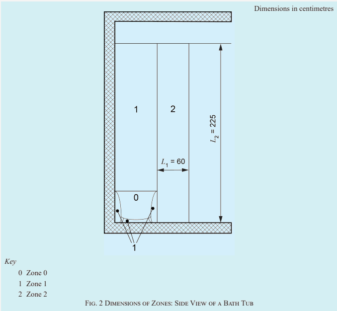
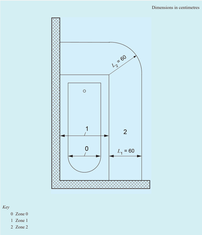
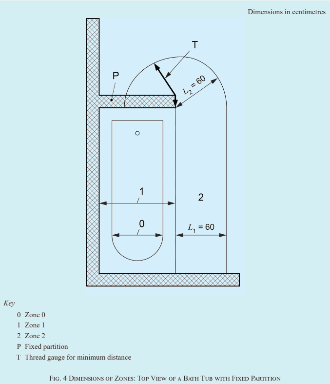
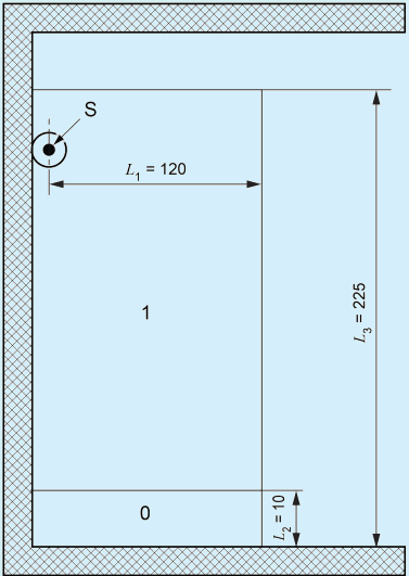
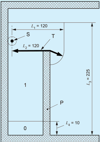
Fixed partitions including horizontal or inclined ceilings, walls with or without windows, doors, floors, may limit the extent of locations containing a bath or shower as well as their zones. Where the dimensions of fixed partitions are smaller than the dimensions of the relevant zones, for example partitions having a height lower than 225 cm, the minimum distance in horizontal and vertical direction shall be taken into account (see Fig. 2 to Fig. 9).
Shower curtains or equivalent flexible material shall not be used for limiting the zones.
Where a shower is located in zone 1 of a bath tub, the zones for a bath tub apply.
Where for showers there is more than one fixed water outlet, the limit of the zones to be considered are those given by the combination of the zones.
4.1.5.5.102 Description of zone 0
Zone 0 is limited:
a) by the interior of a bath tub, see Fig. 2 to Fig. 4;
b) for showers:
from the lowest finished floor level up to a horizontal plane at the height of 10 cm above; and
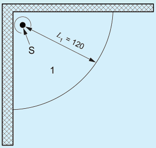
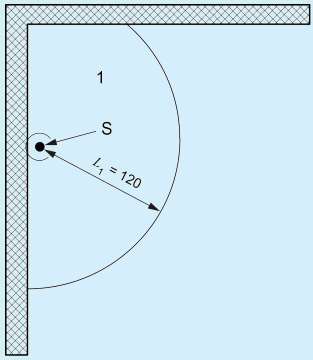
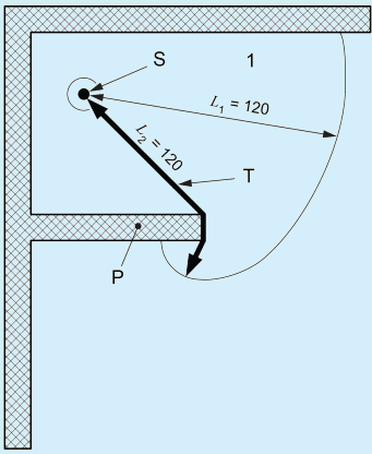
by a vertical circumscribing virtual surface at a distance of 120 cm from the centre of the fixed shower head(s) and/or water outlet(s) limited by fixed partitions restricting the water to enter into the area on the other side of the partition (see Fig. 5, Fig. 6, Fig. 7, Fig. 8 and Fig. 9).
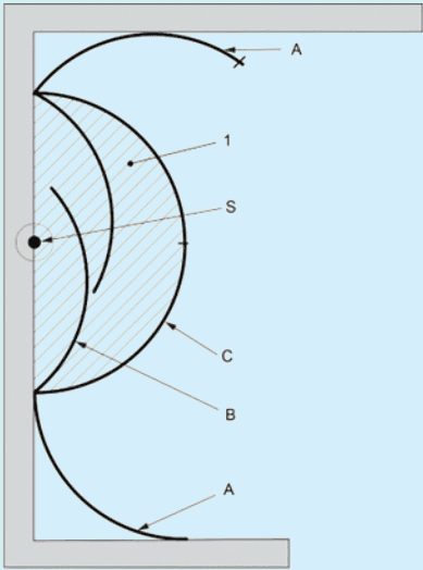
Shower doors intended to be closed when taking a shower are delimiting the zone 0, (see Fig. 10).
4.1.5.5.103 Description of zone 1
Zone 1 is limited:
a) for a bath tub by:
the floor level below the bath tub;
a horizontal plane lying 225 cm above the floor level below the bath tub or a horizontal plane corresponding to the highest fixed shower head, if any, or fixed water outlet, whichever is higher;
the vertical virtual surface circumscribing the bath tub (see Fig. 2 to Fig. 4); and
excluding zone 0.
b) for showers by:
the lowest finished floor level;
a horizontal plane corresponding to the highest fixed shower head or fixed water outlet or the horizontal plane lying 225 cm above the lowest finished floor level, whichever is higher;
the vertical circumscribing virtual surface at a distance of 120 cm from the centre of the fixed shower head(s) and/or fixed water outlet(s) limited by fixed partitions restricting the water to enter into the area on the other side of the partition;
4.2 Protection Against Electric Shock
4.2.1 General Requirements
4.2.2 Replace the Existing Text by the Following:
The protective measure electrical separation shall only be used for:
a) circuits supplying one item of current-using equipment; or
b) one single socket-outlet.
The protective measure electrical separation for the supply shall not be applied for heating cables and embedded heating systems.
4.2.6 Replace the existing text by the following:
The protective measures of obstacles and placing out of reach, as specified in IS 732 : 2019, Annex B shall not be applied.
4.2.7 Replace the existing text by the following:
The protective measures of non-conducting location, earth-free local equipotential bonding and electrical separation for the supply of more than one item of current-using equipment, as specified in IS 732 : 2019, Annex C shall not be applied.
4.2.11 Protective Measure: Automatic Disconnection of Supply
4.2.11.3 Requirements for fault protection
4.2.11.3.1.2 Protective earthing and protective equipotential bonding
4.2.11.3.1.2.101 If no protective equipotential bonding in accordance with IS 732 : 2019, 4.2.11.3.1.2 exists, supplementary protective equipotential bonding in accordance with IEC 60364-4-41 : 2005 and IS 732 : 2019, 4.2.15.2 shall be installed within the location.
4.2.14 Protective Measure: Extra-Low-Voltage Provided by SELV and PELV
4.2.14.1 General
4.2.14.1.101 All electrical equipment installed in zones 0 and 1 shall have basic insulation capable of with standing a test voltage of 500 V a.c. RMS for 1 min.
SP 30 : 2023
All electrical equipment installed in a zone 2 shall have:
basic insulation capable of withstanding a test voltage of 500 V a.c. RMS for 1 min; or
enclosures affording a degree of protection of at least IPXXB or IP2X.
4.2.15 Additional Protection
4.2.15.1 Additional protection: residual current protective devices (RCDs)
4.2.15.1.101 Except for circuits with protective measures “SELV or PELV” or “protection by electrical separation”, additional protection by the use of one or more RCDs having a rated residual operating current not exceeding 30 mA shall be provided for:
5Selection and Erection of Electrical Equipment
5.1 Common Rules
5.1.2 Operational Conditions and External Influences
5.1.2.2 External influences
5.1.2.12.101 Erection of equipment according to external influences
5.1.2.2.101.1 General
Electrical equipment that is likely to be exposed to water jets (e.g. for cleaning purposes) shall have a degree of protection at least IPX5. A higher degree of protection shall be considered if more severe conditions are expected.
EXAMPLE — For a luminaire extending from zone 1 to zone 2, the requirements of zone 1 apply.
For flush mounted electrical equipment in parts of walls, floor or ceilings limiting a zone, the requirements of that zone apply.
5.1.2.2.101.2 Zone 0
Only fixed current using equipment may be erected provided that the equipment:
complies with the relevant standard and is suitable for use in that zone according to the manufacturer’s instructions for use and mounting;
is permanently connected;
is protected by SELV with a rated voltage not exceeding 12 V a.c. or 30 V d.c., with the source of supply installed outside of zones 0 and 1; and
has a degree of protection at least IPX7.
5.1.2.2.101.3 Zone 1
Only the following equipment may be erected:
a) current-using equipment protected by SELV or PELV with a rated voltage not exceeding 25 V a.c. or 60 V d.c., with the source of supply installed outside zones 0 and 1; or
b) socket-outlets of circuits protected by SELV or PELV with a rated voltage not exceeding 25 V a.c. or 60 V d.c., with the source of supply installed outside zones 0 and 1; or
c) fixed or stationary current-using equipment permanently connected and suitable for installation in zone 1 according to the manufacturer’s instruction for use and mounting; or
d) junction boxes and fittings necessary for the supply of equipment installed according to a), b) and c).
Equipment shall have a degree of protection at least IPX4.
EXAMPLE — Equipment likely to be installed in zone 1 includes hot tubs, shower pumps, ventilation equipment, towel rails, water heating appliances, luminaires, washing machines, active glazing, infrared and ultraviolet emitters.
5.1.2.2.101.4 Zone 2
Only the following equipment may be erected:
fixed current-using equipment, having a degree of protection of at least IPX4, that is permanently connected;
socket-outlets, having a degree of protection of at least IPX4, of circuits protected by SELV or PELV with the source of supply installed outside zones 0 and 1;
electrical accessories, other than socket-outlets, having a degree of protection at least IPX4, that are permanently connected;
shaver supply units according to IEC 61558-2-5. If the shaver supply unit is located such that direct spray from the shower is likely, it shall have a degree of protection of at least IPX4.
5.2Wiring Systems
5.2.5 Selection and Erection of Wiring Systems in Relation to External Influences
5.2.5.3 Presence of water (AD) or high humidity (AB)
5.2.5.3.101 Wiring systems that do not supply equipment in zone 0 shall not be routed through zone 0.
5.2.5.8 Other mechanical stresses (AJ)
5.2.5.8.101
NOTE — The following requirements are given to reduce the risk of damaging the wiring caused by drilling holes in the wall, for e.g., mounting handles.
The following requirements apply:
a) Wiring systems supplying current using equipment in zones 0, 1 or 2 and erected in parts of walls which are limiting these zones shall be mounted:
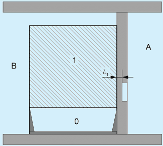
Key
0 Zone 0
1 Zone 1
A Other room
B Bathroom
L 1 Remaining wall thickness, minimum 6 cm
Fig. 1 Remaining Wall Thickness Behind Zones
SP 30 : 2023
either vertically from above or horizontally through the adjacent wall on the rear of the appliance when the fixed equipment is mounted above the bath tub or shower basin, for showers without a basin above the surface of the finished floor level (e.g. water heating appliances);
either vertically rising from below or horizontally through the adjacent wall on the rear of the appliance when the equipment is placed in the space below the bath tub or shower basin.
b) All other embedded wiring systems including their accessories in parts of walls or partitions which limit a zone 0, 1 or 2 shall not be mounted at a depth less than 6 cm from the wall surface limiting the zone, see L 1 in Fig. 1.
c) Where a) or b) are not fulfilled, wiring systems may be erected either if:
the circuits are protected either by one of the protective measures SELV or PELV or electrical separation; or the circuits are protected by additional protection according to IS 732 : 2019, 4.2.15.1 provided by RCDs with a rated residual operating current not exceeding 30 mA; such circuits shall contain a protective conductor; or embedded cables incorporating an earthed screen or a metallic covering which complies with the requirements for a protective conductor of the circuit concerned are used; or the cables are enclosed in an earthed conduit, satisfying the requirements for a protective conductor.
5.3Devices for Protection for Safety, Isolation, Switching, Control and Monitoring
5.3.2 Devices for Protection Against Indirect Contact by Automatic Disconnection of Supply
5.3.2.2 Residual current protective devices
The type of RCD selected for a circuit shall be compatible with the expected loads to be supplied (i.e. RCD of type a.c., type A, type F or type B).
5.3.2.2.101
101 EXAMPLES OF ZONE DIMENSIONS
Fig. 3 Dimensions of Zones: Top View of a Bath Tub without Partition
Dimensions in centimetres
Fig. 5 Dimensions of Zones 0 and 1: Side View of a Shower
0 Zone 0
S Fixed water outlet
1 Zone 1
SP 30 : 2023
Dimensions in centimetres
Key
0 Zone 0
1 Zone 1
P Fixed partition
Fig. 6 Dimensions of Zones 0 and 1: Side View of a Shower with Fixed Partition
T Thread gauge for minimum distance
S Fixed water outlet
Dimensions in centimetres
Key
1 Zone 1
S Fixed water outlet
Fig. 7 Dimensions of Zones 0 and 1: Top View of a Shower with Fixed Water Outlet Close to a Corner
Dimensions in centimetres
1 Zone 1
S Fixed water outlet
Fig. 8 Dimensions of Zones 0 and 1: Top View of a Shower with Fixed Water Outlet at a Distance From a Corner
SP 30 : 2023
Dimensions in centimetres
1 Zone 0 and zone 1
P Fixed partition
T Thread gauge for minimum distance
Fig. 9 Dimensions of Zones 0 and 1: Top View of a Shower with a Fixed Partition
S Fixed water outlet
Key
1 Zone 0 and zone 1
A Opened shower door
C Shower doors when shower is in use
B Shower doors when shower is not in use
S Fixed water outlet
Fig. 10 Example of Zone for Shower with Doors
SP 30 : 2023
Section 3Requirements for Swimming Pools and Fountains
Swimming pools and fountains can be classified based on the extent of activity involved and the locations they are situated in. They generally utilise electricity for their functioning. The combination of water and electricity can create dangerous and unintended paths of electrical current. Depending on the amount of current, the duration of exposure, and the current path through the body, electrical exposures can result in a broad range of injuries, from minor tingling to severe burns or death.
This section shall cover the requirements for construction and installation of electrical wiring, and other equipment that could be used in swimming pools and fountains.
For the purpose of this part of NEC Part 3 Section 3, the requirements of IS 732 : 2019 and shall apply. This Part 3/Sec 3 of NEC contain particular requirements for special installations or locations which are based on the requirements of the general parts of IS 732 : 2019. Part 3/Sec 3 parts are considered in conjunction with the requirements of the general parts.
The particular requirements of this part of NEC supplement, modify or replace certain of the requirements of the general parts of IS 732 : 2019 being valid at the time of publication of this part. The absence of reference to the exclusion of a part or a clause of a general part means that the corresponding clauses of the general part are applicable. Numbering of clauses does not, therefore, necessarily follow sequentially.
1 SCOPE
The particular requirements of this section of NEC apply to electrical installations of:
a) basins of swimming pools and paddling pools and their surrounding zones;
b) areas in natural waters, lakes in gravel pits and coastal and similar areas, specially intended to be occupied by persons for swimming, paddling and similar purposes, and their surrounding zones. Such areas in natural waters, lakes in gravel pits and coastal and similar areas, are considered as swimming pools;
c) basins of fountains and their surrounding zones.
NOTE — In these areas, in normal use, the effect of an electric shock is increased by a reduction in body resistance and contact of the body with earth potential.
For swimming pools for medical use, special requirements may apply.
This standard does not cover the use of mobile equipment, e.g. pool cleaning equipment.
2 REFERENCES
IS/IEC No.
Title
IEC 60364-7-702 : 2010 Low-voltage electrical installations — Requirements for special installations or locations — Swimming pools and fountains
IEC 60335-2-41 Household and similar electrical appliances — Safety — Part 2-41: Particular requirements for pumps
732 : 2019 Code of practice for electrical wiring installations
IS/IEC 60529 : 1989 Degrees of protection provided by enclosures (IP Code)
16205 (Part 1) : 2017 Conduit systems for cable management: Part 1 General requirements
IS/IEC No.
IEC 60245 (all parts) Rubber insulated cables — Rated voltages up to and including 450/750 V
IEC 60598-2-18 Luminaires — Part 2: Particular requirements — Section 18: Luminaires for swimming pools and similar applications
3 TERMINOLOGY
For the purposes of this document, the following terms and definitions apply.
3.1 Fountain — Arrangement, typically for decorative purposes, where water issues from a source and fills a basin of some kind.
3.2 Basin of Fountain — Part of the fountain which collects discharged water.
3.3 Swimming Pool — Water basin designed for purposes such as swimming, diving, etc and not for personal cleaning activity.
3.4 Paddling Pool — Water basin with low water level, e.g. for playing or wading.
4 FUNDAMENTAL PRINCIPLES, ASSESSMENT OF GENERAL CHARACTERISTICS
4.1.5.5 Assessment of general characteristics
4.1.5.5.101 General
Add the following:
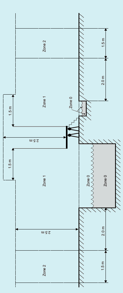
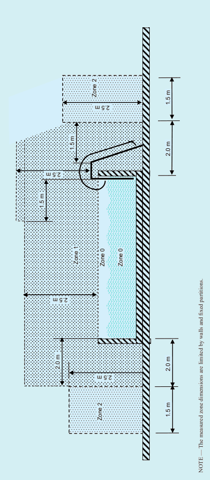
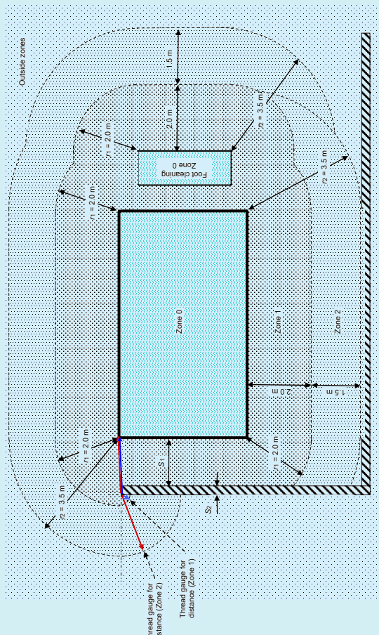
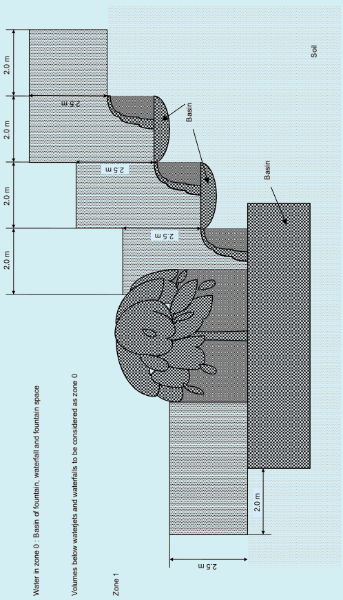
The requirements of this part are based on the dimensions of three zones, zone 0, zone 1 and zone 2 as described in 4.1.5.5.102 to 4.1.5.5.104 (see Fig. A-1 to A-4).
For electrical equipment in parts of walls, floors or ceilings limiting the zones specified in 4.1.5.5.102 to 4.1.5.5.104 but being part of the surface of that wall, floor or ceiling, the same requirements that apply for the zone limited by the surface shall be fulfilled unless specific requirements exist (see 5.5).
The width of zone 1 or zone 2 may be reduced by fixed partitions having a minimum height of 2.5 m.
The requirements for swimming pools also apply to paddling pools.
For basins of fountains which are intended to be occupied by persons, the specifications, and requirements for zone 0 and zone 1 for swimming pools apply.
NOTES
1 Fixed partitions are fixed separating walls, walls including windows and doors. The zones are also limited by ceilings, slopes of roofs and floors. Fixed partitions that are lower than 2.5 m are only limiting if they end at a ceiling or slope of a roof.
2 When a fixed partition is erected inside a zone, its effects on the zone are illustrated in Fig. A-3.
3 For the installation of a prefabricated swimming pool, the requirements of this standard are applicable.
4 Annex A provides some examples of the zones.
4.1.5.5.102 Description of zone 0
This zone comprises
a) the interior of basins, including any recesses in their walls or floors,
b) the interior of basins for foot cleaning, and
c) the interior of waterjets or waterfalls, and the space below them (see Fig. A-4).
NOTE — If the zone cannot be precisely determined under waterjets or waterfalls, it is recommended to take the vertical plane from the rim of the basin as the horizontal limitation of the zone and the maximum height of the water jet or waterfall as the limitation of height.
4.1.5.5.103 Description of zone 1
This zone is limited by
a) the zone 0 boundaries,
b) a vertical plane 2 m from the rim of the basin,
NATIONAL ELECTRICAL CODE OF INDIA
c) the floor or surface expected to be occupied by persons, and
SP 30 : 2023
d) the horizontal plane 2.5 m above the floor or the surface expected to be occupied by persons.
NOTE — Inaccessible equipment installed in an enclosure below the surface of a floor or wall or above a ceiling is not considered to be within zone 1 (see 5.5.5.101.3).
Where the swimming pool contains diving structures, starting blocks, chutes or other components expected to be occupied or accessible by persons, zone 1 also comprises the zone limited by
a) a vertical plane situated 1.5 m around the diving boards, springboards, starting blocks, chutes and other components such as accessible sculptures and decorative basins,
b) the horizontal plane 2.5 m above the highest surface expected to be occupied by persons.
4.1.5.5.104 Description of zone 2
This zone is limited by:
a) the vertical plane external to zone 1 and a parallel plane 1.5 m from the former,
b) the floor or surface expected to be occupied by persons, and
c) the horizontal plane 2.5 m above the floor or surface expected to be occupied by persons.
There is no zone 2 for fountains.
NOTE — Inaccessible equipment installed in an enclosure below the surface of a floor or wall or above a ceiling is not considered to be within zone 2 (see 5.5.5.101.3).
4.2Protection Against Electric Shock
NOTES
1 For selection and erection of socket-outlets, see 5.3.
2 For selection and erection of other equipment, see 5.5.
4.2.1 General Requirements
4.2.6 Replace the existing by the following
The protective measures of obstacles and placing out of reach, as specified in Annex B of IS 732, shall not be applied.
4.2.7 Replace the existing by the following
The protective measures of non-conducting location, earth-free local equipotential bonding and electrical separation for the supply of more than one item of current-using equipment, as specified in Annex C of IS 732 shall not be applied.
4.1.101 Particular Requirements For Each Zone
Add the following:
4.1.101.1 Zones 0 and 1 of swimming pools and in areas of natural waters, lakes in gravel pits and coastal and similar areas
In zones 0 and 1 only protection by SELV at a nominal voltage not exceeding 12 V a.c. or 30 V d.c. is permitted, except where 5.5.104 applies. The source of supply shall be installed external to zones 0 and 1. Where the source of supply is installed in zone 2, 5.3 applies.
4.1.101.2 Zones 0 and 1 of fountains
In zones 0 and 1, only the following protective measures shall be employed:
a) SELV (see 4.2.14 of IS 732 : 2019), the source of supply being installed external to zones 0 and 1; or
b) automatic disconnection of supply (see 4.2.11 of IS 732 : 2019) using a residual current protective device with a rated residual operating current not exceeding 30 mA; or
c) electrical separation (see 4.2.13 of IS 732 : 2019), the separation source supplying a single item of equipment and being installed external to zones 0 and 1.
4.1.101.3 Zone 2 of swimming pools and in areas of natural waters, lakes in gravel pits and coastal and similar areas
NOTE — There is no zone 2 for fountains.
One or more of the following protective measures shall be employed:
a) SELV (see 4.2.14 of IS 732 : 2019). The source of supply shall be installed external to zone 0 and 1. Where the source of supply is installed in zone 2, 5.3 applies; or
b) automatic disconnection of supply (see 4.2.11 of IS 732 : 2019) using a residual current protective device with a rated residual operating current not exceeding 30 mA; or
c) electrical separation (see 4.2.13 of IS 732 : 2019). The separation source shall supply a single item of equipment and be installed external to zones 0 and 1. Where the separation source is installed in zone 2, 5.3 applies.
4.2.14 Protective Measure: Extra-Low-Voltage (SELV and PELV)
4.2.14.4 Requirements for SELV and PELV circuits
Add the following in 4.2.14 of IS 732 : 2019
PELV is not permitted.
4.2.14.4.5 Add the following
Where SELV is used, whatever the nominal voltage, basic protection (protection against direct contact) shall be provided by:
a) barriers or enclosures affording at least the degree of protection according to IEC 60529 IP2X or IPXXB, or
b) insulation capable of withstanding a test voltage of 500 V a.c. for 1 min.
All extraneous-conductive-parts in zones 0, 1 and 2 shall be connected by protective equipotential bonding conductors to the protective conductors of the exposed-conductive-parts of equipment situated in these zones.
1 This connection with the protective conductor may be provided in close proximity to the location, for example at an accessory or a distribution board or other equipment.
2 See also 5.2.5.8 and 5.5.101
Extraneous-conductive-parts are conductive parts not forming part of the electrical installation and liable to introduce an electric potential, including the electric potential of a local earth – for the scope of this standard, from outside zones 0, 1 and 2 into these zones. 3 Such parts may, for example, be
a) metallic pipelines for freshwater, waste water, gas, heating, climate control,
b) metallic parts of building construction,
c) metallic parts of the basin construction,
d) metal reinforcement of non-insulating floors,
e) metal reinforcement of concrete basins.
Floors made of individual concrete tiles, the reinforcement of which is fully encapsulated within the tile and not accessible without damaging the tile, are not considered as extraneous-conductive-parts and therefore need not be included in additional protective equipotential bonding.
Concrete tiles without metallic reinforcement, tile coverings and topsoil (e.g. lawn) are not considered as extraneous-conductive-parts and therefore need not be included in additional protective equipotential bonding.
4 The following conductive parts generally need not be included in additional protective equipotential bonding:
a) basin ladders and barriers;
b) diving structure ladders;
c) handrails and handholds on the rim of the basin;
d) grid covers including the mounting frames of overflow pipes;
e) window frames;
NATIONAL ELECTRICAL CODE OF INDIA
f) door frames;
g) starting blocks.
SP 30 : 2023
5Selection and Erection of Electrical Equipment
5.1 Common Rules
5.1.2.1 Operational conditions
5.1.2.2 External influences
Add the following:
Electrical equipment shall have at least the IP code (see IS/IEC 60529) according to Table 1.
Table 1
Minimum IP Numbe (Clause 5.1.2.2)
r Per Zone
Zone
Outdoor, with Waterjets During Cleaning Operation
Outdoor, without Waterjets
Indoor, with Waterjets During Cleaning Operation
Indoor, Without Waterjets
0
IPX5/IPX8
IPX8
IPX5/IPX8
IPX8
1
IPX5
IPX4
IPX5
IPX4
2
IPX5
IPX4
IPX5
IPX2
NOTES
1 IS/IEC 60529 states that, unless there is a relevant product standard, the test conditions for IPX8 are subject to agreement between manufacturer and user.
2 For zone 0, where waterjets during cleaning operations are expected, both IPX5 (to ensure resistance to the operations during the cleaning process) and IPX8 (to ensure resistance to the immersion in the water) are necessary (see 4.3 of IS/IEC 60529). Both IPX5 and IPX8 are necessary because IPX8 does not include protection against water jets.
5.2 Wiring Systems
5.2.5 Selection and Erection in Relation to External Influences
5.2.5.8 Other mechanical stresses
Add the following:
5.2.5.8.101 Erection according to the zones
In zones 0, 1 and 2, wiring systems shall not have accessible metallic covering. Metallic coverings which are inaccessible shall be connected to the supplementary equipotential bonding.
NOTE — Cables should be installed in conduits to facilitate rewiring.
5.2.5.8.102 Limitation of wiring systems according to the zones
In zones 0 and 1, wiring systems shall be limited to those necessary to supply equipment situated in these zones. Circuits erected in zone 2 or in walls, ceilings or floors delimiting zones 0, 1 or 2 and supplying equipment outside the zones shall be:
a) embedded at a minimum depth of 5 cm; or
b) protected by a residual current protective device with a rated residual operating current not exceeding 30 mA; or
c) supplied by SELV; or
d) protected by electrical separation.
5.2.5.8.103 Additional requirements for the wiring of fountains
Only cables of type 66 according to IEC 60245 series or a type with at least equivalent properties shall be used.
NOTE — Their suitability for permanent contact with water should be declared by the cable manufacturer in addition to compliance with IEC 60245-1 and IEC 60245-4.
Only conduit with classification code X5XX according to the resistance to impact in IS 16205-1/IEC 61386-1 shall be used.
For fountains not intended to be occupied by persons the following additional requirements shall be met:
a) cables or insulated conductors in non-metallic conduit for electrical equipment in zone 0 shall be installed as far outside the basin rim as possible and run to the electrical equipment inside the basin by the shortest practicable route. The cables shall be installed in conduits to facilitate rewiring;
b) in zones 0 and 1, cables or insulated conductors in non-metallic conduit shall be installed with suitable mechanical protection.
5.2.5.8.104 Junction boxes
Junction boxes shall not be installed in zone 0.
In zone 1, only junction boxes for SELV circuits are permitted (see 4.1.101).
5.3 Switchgear and Control Gear
Add the following:
In zone 0, no switchgear or control gear, including socket-outlets, shall be installed.
In zone 1, switchgear, control gear and socket-outlets may be installed only if supplied by SELV, the source of supply of which being installed outside zones 0 and 1. Where the source for SELV is installed in zone 2 its supply circuit shall be protected by a residual current protective device with a rated residual operating current not exceeding 30 mA.
In zone 2, switchgear, control gear and socket-outlets are not allowed unless protected by one of the following protective measures:
a) SELV (see 4.2.14.3 of IS 732 : 2019), the source of supply being installed outside zones 0 et 1. Where the source for SELV is installed in zone 2, its supply circuit shall be protected by a residual current protective device with a rated residual operating current not exceeding 30 mA; or
b) automatic disconnection of the supply with additional protection (see 4.2.15.1 of IS 732 : 2019), using a residual current protective device with a rated residual operating current not exceeding 30 mA; or
c) electrical separation (see 4.2.13 of IS 732 : 2019), supplied individually by the separation source which is installed outside zones 0 and 1. Where the source for electrical separation is installed in zone 2 its supply circuit shall be protected by a residual current protective device with a rated residual operating current not exceeding 30 mA.
5.5 Other Equipment
Add the following:
5.5.101 Current-Using Equipment Of Swimming Pools
5.5.101.1 In zones 0 and 1, only fixed current-using equipment especially designed for use in swimming pools may be installed, taking into account the requirements of 5.4.1.2 and 5.4.1.4.2.
5.5.101.2 Fixed connected swimming pool cleaning equipment intended to be used in zones 0 and 1 shall be supplied by SELV not exceeding 12 V a.c. or 30 V d.c. with the source being installed outside zones 0 and 1. Where the source of supply is installed in zone 2, 5.3 applies (see 3.3.4.1.101.1).
5.5.101.3 Feed pumps, or other special electrical equipment especially intended for use in swimming pools located in a room or location adjacent to the swimming pool and accessible via a hatch (or door) located on the deck surrounding the swimming pool, shall be protected by one of the following protective measures:
a) SELV not exceeding 12 V a.c. or 30 V d.c. with the source being installed outside zones 0 and 1. Where the source of supply is installed in zone 2, 5.3 applies (see 4.1.101.1);
b) electrical separation according to 4.2.13 of IS 732 with simultaneous fulfilment of the following conditions:
where the pump or other equipment is connected to the swimming pool basin, the connection shall only be made by non-conductive water piping;
it shall only be possible to open the hatch or the door by means of a key or tool;
all equipment installed in the room or location shall have a degree of protection of at least IPX5 or such protection shall be provided by an enclosure.
SP 30 : 2023
c) automatic disconnection of the power supply with simultaneous fulfilment of the following conditions:
where the pump or other equipment is connected to the swimming pool basin, the connection shall be made by either electrically insulated water piping, or metal water piping connected to the pool basin’s equipotential bonding:
it shall only be possible to open the hatch or the door by means of a key or tool;
all equipment installed in the room or location shall have a degree of protection of at least IPX5 or such protection shall be provided by an enclosure;
additional equipotential bonding shall be installed in accordance with 4.2.15.2;
the equipment shall be protected by a residual current protective device with a rated residual operating current not exceeding 30 mA.
NOTE — The room where the equipment is located is considered to be outside zones 1 and 2.
5.5.102 Underwater Lighting of Swimming Pools
Luminaires for use in the water or in contact with the water shall comply with IEC 60598-2-18.
Section 4 Requirements for Special Installations or Locations — Rooms and Cabins Containing Sauna Heaters
Rooms and cabins containing sauna heaters are considered as special locations necessitating distinct electrical requirements because of the increased electric shock risk associated with, extreme high temperatures with high humidity, lack of clothing and reduced skin resistance. This section shall cover the requirements for construction and installation of electrical wiring, and other equipment that could be used in locations containing sauna heaters.
For the purpose of this part of NEC Part 3/Sec 4, the requirements of IS 732 : 2019 shall apply. This Part 3/Sec 4 of NEC contain particular requirements for special installations or locations which are based on the requirements of the general parts of IS 732 : 2019. Part 3/Sec 4 parts are considered in conjunction with the requirements of the general parts.
The particular requirements of this part of NEC supplement, modify or replace certain of the requirements of the general parts of IS 732 : 2019 being valid at the time of publication of this part. The absence of reference to the exclusion of a part or a clause of a general part means that the corresponding clauses of the general part are applicable. Numbering of clauses does not, therefore, necessarily follow sequentially
1 SCOPE
The particular requirements of this section (Part 3/Sec 4) of NEC apply to:
a) sauna cabins erected on site, for example, in a location or in a room.
b) the room where the sauna heater is, or the sauna heating appliances are installed. In this case the whole room is considered as the sauna.
They do not apply to prefabricated sauna cabins complying with a relevant equipment standard.
Where facilities like cold water basins or showers, etc. are installed, the requirements of Part 3/Sec 2 also apply.
2 REFERENCES
IS/IEC Number
732 : 2019
NEC Part 3/Sec 2
Code of practice for electrical wiring installations
IEC 60335-2-53
National Electric Code: Part 3 Requirements for special installations or locations. Section 2 Locations containing a bath or shower
Household and similar electrical appliances — Safety — Part 2-53: Particular requirements for sauna heating appliances
4 FUNDAMENTAL PRINCIPLES, ASSESSMENT OF GENERAL CHARACTERISTICS
4.1.5.5 Assessment of general characteristics
4.1.5.1.1 General
When applying this standard, the zones specified in 4.1.5.11.1 to 4.1.5.11.3 shall be taken into account.
4.1.5.11.1 Description of Zone 1
4.2 Protection for Safety – Protection Against Electric Shock
4.3.2.3.11 Protection against direct contact shall be provided for all electrical equipment by:
a) barriers or enclosures affording a degree of protection of at least IPXXB or IP2X, or
b) insulation capable of withstanding a test voltage of 500 V a.c. r.m.s for 1 min.
4.1.2.1 Protection against direct contact
4.1.2.1.101 Obstacles
Protection against direct contact by means of obstacles is not permitted.
4.1.2.1.102 Placing out of reach
Protection against direct contact by placing out of reach is not permitted.
4.2.11.3.3 Additional protection by residual current protective devices (RCDs)
Additional protection shall be provided for all circuits of the sauna, except for the sauna heater, by the use of one or more residual current protective devices with a rated residual operating current not exceeding 30 mA.
4.1.2.2 Protection against indirect contact
4.1.2.2.101 Non-conducting location
Protection against indirect contact by using the protective measure: non-conducting location is not permitted.
4.1.2.2.102 Protection by earth-free local equipotential bonding
Protection against indirect contact by using the measure: earth-free local equipotential bonding is not permitted.
5Selection and Erection of Equipment – Common Rules
5.1.2.2 External influences
The equipment shall have at least the degree of protection IP24.
If cleaning by use of water jets may be reasonably expected, electrical equipment shall be at least IPX5.
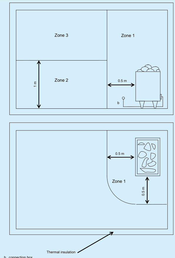
Three zones are defined as shown in Fig. 1:
a) in zone 1: only equipment belonging to the sauna heater shall be installed;
b) in zone 2: there is no special requirement concerning heat resistance of equipment;
c) in zone 3: the equipment shall withstand a minimum temperature of 125 °C and the insulation of wires shall withstand a minimum temperature of 170 °C (see also 5.2 below for wiring).
5.2 Selection and Erection of Electrical Equipment – Wiring Systems
The wiring systems should be preferably installed outside the zones, that is, on the cold side of the thermal insulation. If the wiring system is installed in zone 1 or 3, that is, on the warm side of the thermal insulation, it shall be heat-resistant according to 5.1.2.2 of this section. Metallic sheaths and metallic conduits shall not be accessible in normal use.
5.3 Selection and Erection of Electrical Equipment – Isolation, Switching and Control
5.3.7.6 Functional switching (control)
Switchgear and controlgear which forms part of the sauna heater equipment or of other fixed equipment installed in zone 2, may be installed within the sauna room or cabin according to the manufacturer’s instructions. Other switchgear and controlgear, for example, lighting, shall be placed outside the sauna room or cabin. Socket-outlets shall not be erected within the location containing the sauna heater.
5.5 Other Equipment
Sauna heating appliances shall be installed according to manufacturer’s instructions, see 7.12.1 of IEC 60335-2-53.
b connection box
Fig. 1 Zones of Ambient Temperature
Section 5 Requirements for Special Installations or Locations — Construction and Demolition Site Installations
There is some confusion about the standard, maintenance, and testing of appliances and equipment on construction and demolition sites. Because of the short-term nature of these sites, the electrical equipment used is often sourced from multiple locations, or multiple contractors. It can be difficult to ensure that they have been appropriately maintained and tested prior to their use on the site. This section provides requirements electrical installations for the purpose of the ‘construction and demolition work’.
For the purpose of this part of NEC Part 3 Section 5, the requirements of IS 732 : 2019 shall apply. This Part 3 Section 5 of NEC contain particular requirements for special installations or locations which are based on the requirements of the general parts of IS 732 : 2019. Part 3 Section 5 parts are considered in conjunction with the requirements of the general parts.
The particular requirements of this part of NEC supplement, modify or replace certain of the requirements of the general parts of IS 732 : 2019 being valid at the time of publication of this part. The absence of reference to the exclusion of a part or a clause of a general part means that the corresponding clauses of the general part are applicable. Numbering of clauses does not, therefore, necessarily follow sequentially
1 SCOPE
The requirements of this section (Part 3/Sec 5) of NEC apply to installations for construction and demolition sites for use during the period of the construction or demolition work which are intended to be taken out of service upon completion of the works. Examples include the following:
a) construction work of new buildings;
b) repair, alteration, extension or demolition of existing buildings or parts of existing buildings;
c) engineering works;
d) earthworks;
e) work of similar nature.
The requirements apply to fixed or moveable installations.
445
The requirements do not apply to installations in administrative locations of construction sites (for example, offices, cloakrooms, meeting rooms, canteens, restaurants, dormitories, toilets).
2 REFERENCES
IS/IEC/ISO Number
IS/IEC 61439-4 : 2012 Low-voltage switchgear and controlgear assemblies: Part 4 Particular requirements for assemblies for construction sites (ACS)
IS/IEC 60309-2 : 2002 Plugs, socket-outlets and couplers for industrial purposes: Part 2 Dimensional interchangeability requirements for pin and contact-tube accessories (first revision)
IS/IEC 60309-1 : 2002 Plugs, socket-outlets and couplers for industrial purposes: Part 1 General requirements (first revision)
IEC 60245-4 : 2011 Rubber insulated cables — Rated voltages upto and including 450/750 V — Part 4: Cords and flexible cables
4.1 Protection for Safety
4.1.2 Protection against Electric Shock
4.2.6 Replace with the following:
The protective measures:
a) obstacles, and
b) placing out of reach
as specified in IS 732 : 2019, Annex B shall not be used.
4.2.7 Replace with the following:
The protective measures:
a) non-conducting location,
b) earth-free equipotential bonding, and
c) electrical separation for the supply of more than one current-using equipment as specified in IS 732 : 2019, Annex C shall not be used.
4.2.101 Circuits supplying socket-outlets with rated current up to and including 32 A and other circuits supplying hand-held electrical equipment with rated current up to and including 32 A shall:
a) be protected by automatic disconnection of supply together with additional protection by the use of residual current devices having a rated residual operating current not exceeding 30 mA (see IS 732 : 2019, 4.2.15.1), or
b) be supplied by SELV or PELV (see IS 732 : 2019, 4.2.14), or
c) have electrical separation of circuits (see IS 732 : 2019, 4.2.13), each socket-outlet and hand-held electrical equipment being supplied by an individual isolating transformer or by separate windings of an isolating transformer.
4.2.11 Protective Measure: Automatic Disconnection of Supply
4.2.11.3 Requirements for fault protection
4.2.11.3.2 Automatic disconnection in case of a fault
4.2.11.3.2.101 For circuits supplying socket-outlets with a rated current exceeding 32 A, residual current devices shall be used as disconnection devices.
4.2.14 Protective Measure: Extra-Low Voltage Provided By SELV and PELV
4.2.14.4 Requirements for SELV and PELV circuits
4.2.14.4.5 Replace the subclause with the following:
Irrespective of the nominal voltage, in a.c. and d.c. circuits, the requirement for basic protection shall be provided by the following:
a) insulation in accordance with IS 732 : 2019, A.1, or
b) barriers or enclosures in accordance with IS 732 : 2019, A.2.
SP 30 : 2023
4.5 Protection Against Voltage Disturbances And Electromagnetic Disturbances
4.5.3.3.2 Protection against transient overvoltage of atmospheric origin or due to switching
4.5.3.3.2.101 Cranes, lifts, cement mixers and similar items of equipment are liable to produce switching overvoltages. Where such equipment is present, consideration should be given to the need for protection against switching overvoltages.
5Selection and Erection of Equipment
5.1 Common Rules
5.1.1 Compliance with Standards
5.1.1.1 Add the following:
All assemblies on construction and demolition sites (ACS) for the distribution of electricity shall be in compliance with the requirements of IS/IEC 61439-4.
Where interchangeability is required:
a) socket-outlets with a rated current not exceeding 16 A shall comply with IS/IEC 60309-2 or relevant national standards, and
b) socket-outlets with a rated current exceeding 16 A but not exceeding 125 A shall comply with IS/IEC 60309-2. Socket-outlets shall comply with IS/IEC 60309-1 where:
a) the rated current exceeds 125 A, or
b) interchangeability is not required.
5.1.2 Operational Conditions and External Influences
5.1.2.2 External influences
Consideration shall be given to the risk of damage to electrical equipment by corrosive substances, movement of structures and vehicles, wear and tear, tension, flexing, impact, abrasion, severing and ingress of liquids or solids.
5.2 Wiring Systems
5.2.5.8 Other mechanical stresses (AJ)
5.2.5.8.101 To avoid damage, cables should not be run across site roads or walkways. Where this is necessary, special protection against mechanical damage and contact with construction plant machinery shall be provided. Particular attention shall be given to the protection of surface run and overhead cables against mechanical damage, given the environment and activities at the construction site.
Flexible cables that are subject to movement shall be IEC 60245-4 type 66 or equivalent, resistant to abrasion and to water.
5.3 Isolation, Switching and Control
5.3.7 Isolation and Switching
5.3.7.3 Isolation
5.3.7.3.2 Devices for isolation
The following requirements are added:
Each assembly for construction sites (ACS) shall incorporate devices for isolating the incoming supply.
Devices for isolating the incoming supply shall be suitable for securing in the off position (see 5.3.7.3.1.2 of IS 732 : 2019) (for example, by providing a padlocking facility on the device or by locating the device inside a lockable enclosure). Safety and standby supplies shall be connected by means of devices arranged to prevent interconnection of the different supplies.
5.6 Safety Services
Add the following:
Site conditions may require the provision of safety services, for example escape lighting.
6Verification
6.101 Site work is in a constant state of change and, therefore, the associated electrical installation is subject to risk of damage or misuse. Therefore, in addition to initial and periodic verification, the installation shall be inspected frequently, for example daily, weekly, or monthly, as appropriate. Examples of some items to be inspected include:
a) the adequacy of connections and the condition of the protective conductors;
b) the condition of flexible conductors and their connections to portable equipment and hand-held equipment;
c) the rating and condition of fuses and the setting of the circuit-breakers to ensure that they are not unduly altered; and
d) the functioning of residual current devices.
SP 30 : 2023
Section 6 Conducting Locations with Restricted Movement
In most installations, access to earthed metal and conducting surfaces is fairly limited and the contact area of the body is generally comparatively low. As a result the likelihood of receiving a fatal electric shock is relatively small. In a conducting location where movement is restricted the situation is quite different.
Conducting locations with restricted movement are classed as special locations as the risk of electric shock is greatly increased. Work in these locations is often done by persons who are not electrically skilled. Conducting locations with restricted movement. Location is comprised mainly of metallic or other conductive parts. A person within the location will come into contact with a substantial portion of the conducting surface. The possibility of breaking the contact between the body and the conducting surface is limited.
For the purpose of this part of NEC Part 3 Section 6, the requirements of IS 732 : 2019 shall apply. This Part 3 Section 6 of NEC contain particular requirements for special installations or locations which are based on the requirements of the general parts of IS 732 : 2019. Part 3 Section 6 clauses are considered in conjunction with the requirements of the general parts.
The particular requirements of this part of NEC supplement, modify or replace certain of the requirements of the general parts of IS 732 : 2019 being valid at the time of publication of this part. The absence of reference to the exclusion of a part or a clause of a general part means that the corresponding clauses of the general part are applicable. Numbering of clauses does not, therefore, necessarily follow sequentially.
1 SCOPE
The particular requirements of this section (Part 3/Sec 6) apply to:
a) fixed equipment within conducting locations with restricted movement; and
b) supplies to equipment used within conducting locations with restricted movement.
2 REFERENCES
IS/IEC/ISO Number
Title
3 TERMINOLOGY
For the purposes of this document, the following terms and definitions apply.
3.1 Conducting Location With Restricted Movement —Location surrounded by mainly extraneous-conductiveparts and where contact through one or more points on a person’s body with the extraneous-conductive-parts is likely and where there is limited possibility of interrupting this contact.
4 PROTECTION FOR SAFETY
4.2 Protection against Electric Shock
General Requirements:
The following requirement is added:
4.1.1 In conducting locations with restricted movement the following protective measures apply to circuits supplying the following current-using equipment:
a) For the supply to hand-held tools and portable equipment:
SELV (4.2.14 of IS 732), or
electrical separation (4.2.13 of IS 732) subject to only one item of equipment being connected to a secondary winding of the isolating transformer. NOTE — An isolating transformer may have several secondary windings.
b) For the supply to handlamps:
SELV (4.2.11 of IS 732).
NOTE — A fluorescent luminaire with built-in step-up transformer with electrically separated windings transformer supplied at SELV is equally permitted.
c) For the supply to fixed equipment:
automatic disconnection of the supply (see 4.2.11 of IS 732) with supplementary equipotential bonding (see 4.2.15.2 of IS 732) that shall connect exposed-conductive-parts of fixed equipment and the conductive parts of the location, or
SELV (see 4.2.14 of IS 732), or
PELV (see 4.2.14 of IS 732) where equipotential bonding shall be provided between all exposed-conductive-parts, all extraneous-conductive-parts inside the conducting location with restrictive movement, and the connection of the PELV system to earth, or
electrical separation (see 4.2.13 of IS 732) subject to one item of equipment being connected to a secondary winding of the isolating transformer, or
by use of Class II equipment or equipment having equivalent insulation (see 4.2.12 of IS 732) provided the supplying circuits are protected by additional protection by the use of residual current devices (see 4.2.15.1 of IS 732) with a rated residual operating current not exceeding 30 mA.
NOTE — A fluorescent luminaire with built-in step-up transformer with electrically separated windings and supplied at SELV is equally permitted.
4.2.3 Replace the existing text with the following
For the supply to mobile equipment, one of the following protective measures shall be applied:
a) SELV in accordance with IS 732 : 2019, 4.2.14, or
b) electrical separation for the supply of one item of current using equipment in accordance with IS 732 : 2019, 4.2.13.3.
NOTE — An isolating transformer can have several secondary windings.
For the supply to fixed equipment, one of the following protective measures shall be applied:
a) automatic disconnection of the supply in accordance with IS 732 : 2019, 4.2.11 together with additional protection by supplementary equipotential bonding in accordance with IS 732 : 2019, 4.2.15.2, or
Section 7 Requirements for Special Installations or Locations — Caravan Parks, Camping Parks and Similar Locations
This section applies to the electrical installations in caravan/camping parks and similar locations providing connection points for supplying leisure accommodation vehicles (including caravans) and tents. It covers circuits intended to supply residential park homes in caravan parks, camping parks and similar locations. In addition it also specifies requirements to socket outlet requirements, RCD protection, and external influences.
For the purpose of this part of NEC Part 3/Sec 7, the requirements of IS 732 : 2019 shall apply. This Part 3/Sec 7 of NEC contain particular requirements for special installations or locations which are based on the requirements of the general parts of IS 732 : 2019. Part 3/Sec 7 clauses are considered in conjunction with the requirements of the general parts.
The particular requirements of this part of NEC supplement, modify or replace certain of the requirements of the general parts of IS 732 : 2019 being valid at the time of publication of this part. The absence of reference to the exclusion of a part or a clause of a general part means that the corresponding clauses of the general part are applicable. Numbering of clauses does not, therefore, necessarily follow sequentially.
1 SCOPE
The particular requirements contained in this section (Part 3/Sec 7) apply only to circuits intended to supply leisure accommodation vehicles, tents or residential park homes in caravan parks, camping parks and similar locations.
NOTE — For the purposes of this document caravan park includes camping parks and similar locations.
The particular requirements do not apply to the internal electrical installations of leisure accommodation vehicles, mobile or transportable units or residential park homes.
2 REFERENCES
IS No./Other Title Publications
12360 : 1988 Voltage bands for electrical installations including preferred voltages and frequency
16205 (Part 24) : 2017 Conduit systems for cable management: Part 24 Particular requirements conduit systems buried under ground
17050 : 2018/ Degrees of protection provided by enclosures for electrical equipment against external IEC 62262 : 2002 mechanical impacts (IK code)
IS/IEC 60309-2 : 2002 Plugs, socket-outlets and couplers for industrial purposes: Part 2 Dimensional interchangeability requirements for pin and contact-tubes accessories (first revision)
IS/IEC 60309-1 : 2002 Plugs, socket-outlets and couplers for industrial purposes — Part 1: General requirements
IEC 60309-4 : 2006 Plugs, socket-outlets and couplers for industrial purposes — Part 4: Switched socket-outlets and connectors with or without interlock
3 TERMINOLOGY
For the purposes of this document, the following terms and definitions apply.
4.1 5.8.2 Types of system earthing
4.1.5.8.2.1 TN-systems
Add the following:
For a TN-system, the final circuit for the supply to a leisure accommodation vehicle, tent or residential park home shall not include a PEN conductor.
4.1.5.9 Supplies
4.1.5.9.1 General
4.1.5.9.1.101 The nominal supply system voltage shall be selected from IS 12360/IEC 60038.
The nominal supply voltage of the installation for the supply of leisure accommodation vehicles shall not exceed 230 V a.c. single-phase and/or 400 V a.c. three-phase and 48 V d.c.
4.1 Protection for Safety
4.1.2 Protection against Electric Shock
General requirements
4.2.6 Add the following:
The protective measures of obstacles and placing out of reach as specified in Annex B of IS 732 shall not be used.
4.2.7 Add the following:
The protective measures of non-conducting location and earth-free local equipotential bonding as specified in Annex C of IS 732 : 2019 shall not be used.
4.2.11.3.3 Additional Protection
4.2.15.1 Residual current protective devices (RCDs)
Every socket-outlet shall be individually protected by an RCD having a rated residual operating current not exceeding 30 mA. Devices selected shall disconnect all live conductors.
A final circuit intended for the fixed connection for a supply to a mobile home or a residential park home shall be individually protected by an RCD having a rated residual operating current not exceeding 30 mA. Devices selected shall disconnect all live conductors.
5Selection and Erection of Electrical Equipment
See IS/IEC TS 61439-7.
5.1 Selection and Erection of Electrical Equipment – Common Rules
5.1.2 Operational Conditions and External Influences
5.1.2.2 External influences
Add the following:
NOTE — In a caravan park or camping park, special consideration is given to the protection of people, due to the fact that the human body can be in contact with earth potential, to the protection of wiring due to tent pegs or ground anchors and to the movement of heavy or high vehicles.
5.2.5.3.101 Presence of water (AD)
Equipment shall be selected with a degree of protection of at least IPX4 in order to protect against water splashes (AD4).
5.2.5.4.101 Presence of solid foreign bodies (AE)
Equipment shall be selected or provided with a degree of protection of at least IP4X in order to protect against the ingress of very small objects (AE3).
5.2.5.6.101 Impact (AG)
Equipment installed in a campsite shall be protected against mechanical damage (impact of high severity AG3). Protection of the equipment shall be afforded by one or more of the following:
a) the position or location shall be selected to avoid damage by any reasonably foreseeable impact;
b) local or general mechanical protection shall be provided; and
c) equipment that complies with a minimum degree of protection against external mechanical impact of IK08 (see IS 17050 : 2018/IEC 62262 : 2002) shall be installed.
5.2 Wiring Systems
5.2.4 Types of Wiring Systems
5.2.4.7 Several circuits in one cable
5.2.4.7.101 Supply for the caravan or tent pitch
The preferred method of supply for feeding the caravan pitch or tent pitch electrical supply equipment is by means of underground distribution circuits.
5.2.4.7.101.1 Underground cables
An underground distribution circuit shall, unless provided with additional mechanical protection, be buried at a sufficient depth to avoid being damaged, for example by tent pegs or ground anchors or by the movement of vehicles.
A depth of 0.6 m is generally considered as a minimum depth to fulfill this requirement. Alternatively the cable may be installed outside the pitch or other area where tent pegs or ground anchors may be driven.
NOTE — For conduit systems buried underground, see IS 16205-24.
5.2.4.7.101.2 Overhead cables or overhead insulated conductors
Every overhead conductor shall be insulated.
Poles and other supports for overhead wiring shall be located or protected so that they are unlikely to be damaged by any foreseeable movement of vehicles.
NATIONAL ELECTRICAL CODE OF INDIA
Every overhead conductor shall be at a height above ground of not less than 6 m in all areas subject to the movement of vehicles and 3.5 m in all other areas.
SP 30 : 2023
5.3 Isolation, Switching and Control
5.3.4 Devices for Protection Against Overcurrent
In addition the following applies:
Every socket-outlet shall be individually protected by an overcurrent protective device, in accordance with the requirements of 4.4 of IS 732.
A fixed connection for a supply to a mobile home or residential park home shall be individually protected by an overcurrent protective device, in accordance with the requirements of 4.4 of IS 732.
5.3.7 Isolation and Switching
5.3.7.3 Isolation
5.3.7.3.1 General
5.3.7.3.1.1 Add the following:
At least one means of isolation shall be installed in each distribution cabinet. This device shall disconnect all live conductors.
5.5 Other Equipment
5.5.101 Socket-Outlets
5.5.101.1 Every socket-outlet shall comply with IS/IEC 60309-2.
Every socket-outlet shall meet the degree of protection of at least IP44 or such protection shall be provided by an enclosure.
To prevent the socket contacts being live when accessible, every socket-outlet or connector shall either comply with IS/IEC 60309-2 and shall be interlocked and classified according to IS/IEC 60309-1 : 1999, or shall be part of an interlocked self-contained product complying with IEC 60309-4 and classified according to IEC 60309-4 : 2006.
5.5.101.2 Every socket-outlet shall be located as close as practicable to the caravan pitch or tent pitch to be supplied.
Socket-outlets shall be installed in the distribution board or in separate enclosures.
5.5.101.3 In order to avoid any hazard due to long connection cables no more than four socketoutlets shall be grouped together in any one enclosure. To ensure that the degree of protection is maintained when the socket-outlets are in use, no more than four socket-outlets shall be mounted within the same enclosure.
Columns (pillars) should be located so as to minimize the need for extension cables to cross gangways, etc.
5.5.101.4 Every caravan pitch or tent pitch shall be supplied with at least one socket-outlet.
5.5.101.5 The current rating of socket-outlets shall be not less than 16 A.
5.5.101.6 The lowest part of any socket-outlet shall be placed at a height between 0.5 m and 1.5 m from the ground. In special cases of extreme environmental conditions, it is permitted to exceed the stated maximum height of 1.5 m. In such cases, special measures shall be taken to ensure the safe insertion and removal of plugs.
NOTE — This can be necessary if the caravan park or camping park risks being flooded. This can also be necessary if the caravan park is used during winter after heavy snow falls.
Section 8 Requirements for Special Installations or Locations — Marinas and Similar Locations
Marinas and similar locations are considered to be locations with an increased risk of electric shock. This is because of the presence of water, a reduction in body resistance, and contact of the body with Earth potential. In this Section we give an overview of the requirements of electrical circuits intended to supply houseboats and pleasure craft in marinas and similar locations
For the purpose of this part of NEC Part 3/Sec 8, the requirements of IS 732 : 2019 shall apply. This Part 3 Section 8 of NEC contain particular requirements for special installations or locations which are based on the requirements of the general parts of IS 732 : 2019. Part 3 Section 8 parts are considered in conjunction with the requirements of the general parts.
The particular requirements of this part of NEC supplement, modify or replace certain of the requirements of IS 732 : 2019 being valid at the time of publication of this part. The absence of reference to the exclusion of a part or a clause of a general part means that the corresponding clauses of the general part are applicable. Numbering of clauses does not, therefore, necessarily follow sequentially.
1 SCOPE
The particular requirements specified in this section (Part 3/Sec 8) of NEC apply only to circuits intended to supply pleasure craft or houseboats in marinas and similar locations.
NOTE — In this part “marina” means “marina and similar locations”.
The particular requirements do not apply to the supply of house boats if they are directly supplied from the public network.
The particular requirements do not apply to the internal electrical installations of pleasure craft or house boats.
NOTES
1 For electrical installations of pleasure craft, see IEC 60092-507.
2 The electrical installations of house boats should comply with the general requirements of IEC 60364, together with the relevant particular requirements of IEC 603647.
For the remainder of the electrical installation of marinas and similar locations the general requirements of IEC 60364 together with the relevant particular requirements of IEC 603647 apply.
2 REFERENCES
IS/IEC/ISO Number
Title
IS/IEC 60309-2 : 2002 Plugs, socket-outlets and couplers for industrial purposes: Part 2 Dimensional interchangeability requirements for pin and contact-tubes accessories (first revision)
IS/IEC 60309-1 : 2002 Plugs, socket-outlets and couplers for industrial purposes: Part 1 General requirements (first revision)
IS 12360 : 1988 Voltage bands for electrical installations including preferred voltages and frequency IS 17050 : 2018/ Degrees of protection provided by enclosures for electrical equipment against external IEC 62262 : 2002 mechanical impacts (IK code)
Annex BB-2 Obstacles
Protection by obstacles shall not be used.
B-3 Placing Out of Reach
Protection by placing out of reach shall not be used.
Annex CC-1 Non-conducting Location
Protection by non-conducting location shall not be used.
NOTE — This precludes the use of class 0 equipment.
C-2 Protection by Earth-free Local Equipotential Bonding
Protection by earth free local equipotential bonding shall not be used.
4.2.13 Protective Measure: Electrical Separation
Where the protective measure of electrical separation is used for supplying pleasure craft compliance with all the requirements of 4.2.13 and with 4.2.13.3.2 and 4.2.13.3.6 shall be ensured.
4.2.13.3.2 The circuit shall be supplied through a fixed isolating transformer complying with IS/IEC 61558-2-4. The protective conductor of the supply to the isolating transformer shall not be connected to the earth terminal in the socket-outlet supplying the pleasure craft.
NOTE — See Annex A.
4.2.13.3.6 Add the following:
The equipotential bonding of the pleasure craft shall not be connected to the protective conductor of the shore supply.
Annex BExample of an Instruction Notice to BE Placed in Marinas
B-1 It is recommended that the marina operator provides every pleasure craft operator who wishes to connect a pleasure craft to an electrical supply with an up-to-date copy of this instruction notice and also installs an up-to-date, clearly legible and weather protected copy of this instruction notice at every supply point.
B-2 The instruction notice should be in the national language(s) of the country and in English.
B-3 The instruction notice should contain, at least, the following:
Instructions for Connection to the Shore Supply
This marina provides a direct, earthed, connection to the shore supply.
General
a) Unless you have an isolating transformer fitted on board to isolate the electrical system on your craft from the shore supply, there is an increased risk of galvanic corrosion (electrolysis) damaging your craft.
b) The supply voltage at this marina is ……1) V, ……1) Hz (normally 230 V 50 Hz single-phase and 400 V 50 Hz three-phase), supplied by socket-outlets complying with IEC 60309-2.
c) Measures should be taken to prevent the connecting flexible cable or the connectors from falling into the water during connection and disconnection.
d) Only the connecting flexible cable from the craft should be connected to any socket–outlet.
e) Only one craft should be connected to one socket-outlet.
f) The connecting flexible cable should be undamaged and in one length, without joints and the connectors should be in good condition.
g) Moisture, dust and salt in the craft appliance inlet can constitute a serious hazard. Examine the appliance inlet: clean and dry it, if necessary, before plugging in the connecting flexible cable from the marina shore supply.
h) It is dangerous for unskilled persons to attempt repairs or alterations. If any difficulty arises, consult the marina operator.
On arrival
a) After mooring, switch off all current-using equipment on the craft.
b) Examine the flexible cable and its connectors to ensure it is undamaged and in good condition.
c) Connect the flexible cable first at the appliance inlet of the craft and then at the shore supply.
d) Ensure the cable is placed where it will no be damaged and ensure that it will not a trip hazard to other persons.
Before leaving
a) Switch off all current-using equipment on the craft.
b) Disconnect the flexible cable from the socket–outlet on the shore and then from the appliance inlet on the craft.
c) Replace the cover on the appliance inlet on the craft to prevent the ingress of water.
d) Coil up the connecting flexible cable, ensure that the connectors are clean and dry, and store the cable in a dry location where it will not be damaged.
To be completed by the marina operator.
Bibliography
IEC 60092-507, Electrical installations in ships – Part 507: Pleasure craft
IEC 60364-5-52, Electrical installations of buildings – Part 5-52: Selection and erection of electrical equipment – Wiring systems
IEC 61386-24, Conduit systems for cable management – Part 24: Particular requirements – Conduit systems buried underground
Section 9 Requirements for Medical Locations
In medical locations it is necessary to ensure the safety of patients likely to be subjected to the application of medical electrical equipment. For every activity and function in a medical location, the particular requirements for safety have to be considered. Safety can be achieved by ensuring the safety of the installation and the safe operation and maintenance of medical electrical equipment connected to it. The use of medical electrical equipment on patients undergoing intensive care (of critical importance) has called for enhanced reliability and safety of electrical installations in hospitals so as to improve the safety and continuity of supplies which is met by application of this standard. Variations of the standard to further enhance safety and reliability are acceptable.
1 SCOPE
The particular requirements of this section (Part 3/Sec 9) of NEC apply to electrical installations in medical locations so as to ensure safety of patients and medical staff. These requirements, mainly, refer to hospitals, private clinics, medical and dental practices, health care centers and dedicated medical rooms in the work place. The requirements in this section shall be considered in addition to the requirements in other parts of NEC for medical locations.
NOTES
1 It may be necessary to modify the existing electrical installation, in accordance with this standard, when a change of utilization of the location occurs. Special care should be taken where intracardiac procedures are performed in existing installations.
2 Where applicable this standard can also be used in veterinary clinics. The requirements of this part do not apply to medical electrical equipment.
3 For medical electrical equipment; refer to the IS 13450 series.
2 REFERENCES
12032 (Part 1) : 1987 Graphical symbols for diagrams in the field of electrotechnology: Part 1 General information
12032 (Part 11) : 1987 Graphical symbols for diagrams in the field of electrotechnology: Part 11 Architectural and topographical installation plans and diagrams
13450 (Part 1) : 2018 Medical electrical equipment: Part 1 General requirements for basic safety and essential performance (second revision)
14700 (Part 3/Sec 2 and 3) Electromagneticcompatibility (EMC): Part 3 Limits: 2018
IEC 61000-2 series Electromagnetic compatibility (EMC) — Part 2: Environment
IEC 61082-1 : 2014 Preparation of documents used in electrotechnology — Part 1: Rules
IEC 61557-8 : 2014 Electrical safety in low voltage distribution systems up to 1000 Vac. and 1500 Vd.c. — Equipment for testing, measuring or monitoring of protective measures — Part 8: Insulation monitoring devices for IT systems
IEC 61558-2-15 : 2011 Safety of transformers + reactors + power supply units and combinations thereof — Part 2-15: Particular requirements and tests for isolating transformers for the supply of medical locations
5.1 Types of System Earthing
The TN-C system is not allowed in medical locations and medical buildings downstream of the main distribution board.
5.2 Power Supply
5.2.1 General
In medical locations the distribution system should be designed and installed to facilitate the automatic change-over from the main distribution network to the electrical safety source feeding essential loads (according to IS 732).
5.2.2 Supplies for electric supply systems for safety services and standby systems in medical locations of group 1 and group 2
In medical locations of group 1 and group 2, the distribution system shall be designed and installed to facilitate the automatic transfer switching or automatic change-over equipment from the main distribution network to the electric source for safety services feeding essential loads (see 5.6 of IS 732). Consideration shall be given to all other essential medical and non-medical loads.
Consideration should also be given to the inrush current of any connected equipment.
NOTE — This could also apply to group 0 medical locations.
5.2.3 Power supply for medical locations of group 2
In case of a single fault in the power supply, a total loss of power shall be prevented. This may be achieved by:
– provision of two independent supply lines, and/or
• a UPS within the same fire section for supplying the medical IT system, or
• a UPS that supplies a number of group 2 locations.
SP 30 : 2023
5Selection and Erection of Electrical Equipment
5.1.2 Operational Conditions and External Influences
5.1.2.2 External influences
Add the following:
NOTE — For marinas particular attention is given in this part to the likelihood of corrosive elements, movement of structures, mechanical damage, presence of flammable fuel and the increased risk of electric shock due to:
a) presence of water;
b) reduction in body resistance;
c) contact of the body with earth potential.
5.2.5.4 Presence of water (AD)
In marinas, equipment installed on or above a jetty, wharf, pier or pontoon shall be selected as follows, according to the external influences which may be present:
a) water splashes (AD4): IPX4;
b) water jets (AD5): IPX5;
c) water waves (AD6): IPX6.
5.2.5.4 Presence of solid foreign bodies (AE)
Equipment installed on or above a jetty, wharf, pier or pontoon shall be selected with a degree of protection of at least IP4X in order to protect against the ingress of very small objects (AE3).
5.2.5.5 Presence of corrosive or polluting substances (AF)
Equipment installed on or above a jetty, wharf, pier or pontoon shall be suitable for use in the presence of atmospheric corrosive or polluting substances (AF2). If hydrocarbons are present AF3 is applicable.
5.2.5.6 Impact (AG)
Equipment installed on or above a jetty, wharf, pier or pontoon shall be protected against mechanical damage (impact of medium severity AG2). Protection shall be afforded by one or more of the following:
a) the position or location of the equipment shall be selected to avoid being damaged by any reasonably foreseeable impact;
b) local or general mechanical protection shall be provided;
c) equipment shall be installed which complies with a minimum degree of protection for external mechanical impact of IK07 (see IS 17050 : 2018/IEC 62262 : 2002).
5.2.4 Types of Wiring Systems
709.521.7 Wiring systems of marinas
709.521.7.1 The following wiring systems are suitable for distribution circuits in marinas:
a) underground cables;
b) overhead cables or overhead insulated conductors;
c) cables with copper conductors and thermoplastic or elastomeric insulation and installed within an appropriate cable management system taking into account external influences such as movement, impact, corrosion and ambient temperature;
SP 30 : 2023
d) mineral-insulated cables with PVC protective covering;
e) armoured cables with a thermoplastic or elastomeric covering;
f) other cables and materials that are no less suitable than those listed under a), b), c), d) or e) above.
709.521.7.2 The following wiring systems shall not be used on or above a jetty, wharf, pier or pontoon:
a) overhead cables and overhead conductors in free air suspended from or incorporating a support wire, e.g. as installation method Nos. 35 and 36 in Table 19, Annex R of IS 732;
b) insulated conductors in conduits, trunking etc., e.g. as installation methods Nos. 4 and 6 in Table 19, Annex R of IS 732;
c) cables with aluminium conductors; and
d) mineral-insulated cables.
709.521.7.3 Cables and cable management systems shall be selected and installed so that mechanical damage due to tidal and other movement of floating structures is prevented.
Cable management systems shall be installed to allow the drainage of water/condensate e.g. by sloping way and/or drainage holes.
709.521.7.4 Underground cables
Underground distribution circuits shall, unless provided with additional mechanical protection be buried at a sufficient depth to avoid being damaged, e.g. by movement of vehicles.
NOTES
1 A depth of 0.5 m is generally considered as a minimum depth to fulfil this requirement.
2 For conduit systems buried underground, see IS 16205-24/IEC 61386-24.
709.521.7.5 Overhead cables or overhead insulated conductors
All overhead conductors shall be insulated.
Poles and other supports for overhead wiring shall be located or protected so that they are unlikely to be damaged by any foreseeable movement of vehicles.
Overhead conductors shall be at a height above ground of not less than 6 m in all areas subjected to movement of vehicles movement and 3.5 m in all other areas.
5.3.2 Devices for Protection against Indirect Contact by Automatic Disconnection of supply
5.3.2.2 Residual current protective devices (RCD’s)
Add the following:
Every socket-outlet with a rated current up to 63 A shall be individually protected by an RCD having a rated residual operating current not exceeding 30 mA. The RCD selected shall disconnect all poles, including the neutral.
Every socket-outlet with a rated current above 63 A shall be individually protected by an RCD having a rated residual operating current not exceeding 300 mA. The RCD selected shall disconnect all poles, including the neutral.
Account should be taken of the need for selectivity, e.g. by the use of Type S.
Every final circuit intended for the fixed connection of a supply to a house boat shall be protected individually by an RCD having a rated residual operating current not exceeding 30 mA. The RCD selected shall disconnect all poles, including the neutral.
5.3.4 Devices for Protection against Overcurrent
In addition the following applies:
Each socket – outlet shall be individually protected by an overcurrent protective device, in accordance with the requirements of 4.4 of IS 732.
Every final circuit intended for the fixed connection of a supply to a house boat shall be individually protected by an overcurrent protective device, in accordance with the requirements of 4.4 of IS 732.
5.3.7 Isolation and Switching
5.3.7.3 Isolation
5.3.7.3.1 General
5.3.7.3.1.1 At least one means of isolation shall be installed in each distribution board. This device shall disconnect all live conductors including the neutral conductor.
5.5 Other Equipment
5.5.101 Socket-Outlets General
5.5.101.1 Every socket-outlet with a current rating up to 63 A shall comply with IEC 60309-2. Every socket-outlet with a current rating over 63 A shall comply with IEC 60309-1.
Every socket-outlet shall meet the degree of protection of at least IP44 or such protection shall be provided by an enclosure.
Where the codes AD 5 or AD 6 are applicable the degree of protection shall be at least IPX5 or IPX6 respectively.
5.5.101.2 Every socket-outlet shall be located as close as practicable to the berth to be supplied.
Socket-outlets shall be installed in the distribution board or in separate enclosures.
5.5.101.3 In order to avoid any hazard due to long connection cords no more than four socket-outlets shall be grouped together in any one enclosure.
NOTE — See Annex B regarding recommended notices to be placed in marinas adjacent to each group of socket-outlets.
5.5.101.4 One socket-outlet shall supply only one pleasure craft or house boat.
5.5.101.5 In general single phase socket-outlets with rated voltage 200 V – 250 V and rated current 16 A shall be provided.
Where greater demands are envisaged socket-outlets with higher ratings may be provided.
5.5.101.6 Every socket-outlet, both on fixed jetties or piers and on floating pontoons, shall be placed in such a position as to avoid the effect of splashing and/or submersion unless appropriate measures are taken.
ANNEX A
(Informative)
EXAMPLES OF METHODS OF OBTAINING SUPPLY IN MARINAS
NOTE — In the Fig. A.1 through A.5 functional switches are not shown.
There is a risk of electrolytic corrosion resulting from circulating galvanic currents in the protective conductor to shore.
Fig. A-1 Direct Connection to A Single Phase Mains Supply
No connection shall be made between the PE conductor of the vessel and the PE conductor of the shore supply. This is to prevent galvanic currents circulating between the hull of the vessel and metallic parts on the shore side.
Fig. A-2 Direct Connection to a Single Phase Mains Supply with an Isolating Transformer on The Vessel
6Protection for Safety
For Protection for Safety, please refer to relevant items under 4 of IS 732. Additional requirements have been mentioned against each sub-clause below.
6.1 Protection Against Electric Shock
6.1.1 Protection against Both Direct and Indirect Contact
6.1.1.1 SELV and PELV
When using SELV and/or PELV circuits in medical locations of group 1 and group 2, the nominal voltage applied to current-using equipment shall not exceed 25 V r.m.s. a.c. or 60 V ripple free d.c.. Protection by insulation of live parts according to 4.2.12.1 of IS 732 and by barriers or enclosures according to 4.2.12.2 of IS 732 is essential. In medical locations of group 2, exposed-conductive-parts of equipment (for example, operating theatre luminaries), shall be connected to the equipotential bonding conductor.
6.1.2 Protection Against Direct Contact
6.1.2.1 Obstacles
Protection by obstacles is not permitted.
6.1.2.2 Placing out of reach
Protection by placing out of reach is not permitted.
Only protection by insulation of live parts or protection by barriers or enclosures is permitted.
6.1.3 Protection Against Indirect Contact
6.1.3.1 Automatic disconnection of supply
6.1.3.1.1 Disconnection of supply
In medical locations of group 1 and group 2, the following shall apply:
a) For IT, TN and TT systems, the conventional touch voltage U L shall not exceed 2 5 V ( U L ≤ 2 5 V ) ); and b) For TN and IT systems, Table 1 shall apply.
Table 1 Maximum Disconnecting Times
(Clause 6.1.3.1.1)
TN system
IT system
Installation Nominal Voltage
Disconnecting Times
Installation Nominal Voltage
Disconnecting Times
Uo a V
Uo/U V
Neutralnot distributed
Neutral distributed
120
0.35
120-240
0.4
1
230
0.2
230/400
0.2
0.5
277
0.2
277/480
0.2
0.5
400, 480
0.05
400/690
0.06
0.2
580
0.02b
580/1 000
0.02b
0.08
a Uo is the voltage between phase and neutral. b If such disconnecting time cannot be guaranteed, it is necessary to take other protective measures, such as supplementary equipotential bonding.
NOTE— Disconnection of supply when overload or short-circuit conditions occur, can be achieved by different design methods within the procedures of the general rules in order to satisfy the required safety level.
6.1.3.1.1.1 TN systems
In medical locations of group 1, in final circuits with overcurrent protective devices rated up to 32 A, residual current protective devices with a rated residual operating current not exceeding 30 mA shall be used.
In medical locations of group 2 protection by automatic disconnection of supply by means of residual current protective devices with a rated residual-operating current not exceeding 30 mA shall only be used on the following circuits that are supplying only one single equipment:
Final circuits of ME equipment and ME systems shall be for the exclusive use of such equipment.
Except those of the medical IT system, additional protection by residual current protective devices with a rated residual operating current not exceeding 30 mA shall be used in all final circuits as follows:
a) medical locations of group 1 with overcurrent protective devices rated 32A and below; and
b) medical locations of group 2.
6.1.3.1.1.2 TT systems
In medical locations of group 1 and group 2, the requirements of TN systems apply and, in all cases, residual current protective devices shall be used.
6.1.3.1.1.3 Medical IT system
In Group 2 medical locations, an IT system shall be used for final circuits and where the same final circuit is connected to more than one ME equipment or ME system, located within the patient environment, excluding:
a) equipment with a rated power greater than 5kVA;
b) X-ray equipment; and
c) the supply of movements of fixed operating tables.
In medical locations of group 2, the supply to final circuits for socket-outlets for ME equipment and ME systems used for life-support of the patient, shall not be automatically disconnected in the event of a first fault.
For each group of rooms serving the same function, at least one separate medical IT system is necessary. The medical IT system shall be equipped with an insulation monitoring device in accordance with IEC 61557-8 with the following specific requirements:
a) The a.c. internal impedance shall be at least 100 kΩ;
b) The test voltage shall not be greater than 25 V d.c.;
c) The injected current, even under fault conditions, shall not be greater than 1mA peak; and
d) Indication shall take place at the latest when the insulation resistance has decreased to 50 kΩ. A test device shall be provided;
NOTE — The necessary additional requirements on IMDs given above are at this time not covered in the equipment standard IEC 61557-8. They will be removed from this publication as soon as they have been treated in the relevant equipment standard.
For each medical IT system, an acoustic and visual alarm system incorporating the following components shall be arranged at a suitable place so that it can be permanently monitored (audible and visual signals) by the medical staff:
a) A green signal lamp to indicate normal operation;
b) A yellow signal lamp which lights when the minimum value set for the insulation resistance is reached. It shall not be possible for this light to be cancelled or disconnected;
c) An audible alarm which sounds when the minimum value set for the insulation resistance is reached. This audible alarm may be silenced; and
d) The yellow signal shall go out on removal of the fault and when the normal condition is restored.
Monitoring of overload and high temperature for the medical IT transformer is required.
6.1.3.1.2 Supplementary equipotential bonding
In each medical location of group 1 and group 2, supplementary equipotential bonding conductors shall be installed and connected to the equipotential bonding bus bar for the purpose of equalizing potential differences between the following parts, located in the “patient environment”:
a) Protective conductors;
b) Extraneous-conductive-parts;
SP 30 : 2023
c) Screening against electrical interference fields, if installed;
d) Connection to conductive floor grids, if installed; and
e) Metal screen of the isolating transformer, if any.
NOTE — Fixed conductive non-electrical patient supports such as operating theatre tables, physiotherapy couches and dental chairs should be connected to the equipotential bonding conductor unless they are intended to be isolated from earth.
6.1.3.1.3 In medical locations of group 2, the resistance of the conductors, including the resistance of the connections, between the terminals for the protective conductor of socket-outlets and of fixed equipment or any extraneous-conductive-parts and the equipotential bonding bus bar shall not exceed 0.2 Ω.
NOTE— This resistive value can also be determined by the use of a suitable cross-sectional area of the conductor.
6.1.3.1.4 The equipotential bonding bus bar shall be located in or near the medical location. In each distribution board or in its proximity, an additional equipotential bonding bar shall be provided to which the supplementary equipotential bonding conductor and protective earth conductor shall be connected. Connections shall be so arranged that they are clearly visible and easily disconnected individually.
6.1.4 Fire Protection
In medical locations of Group 1 and 2 Arc Fault Detection Devices (AFDDs) are not required to be installed.
In medical locations of Group 0 any Arc Fault Detection Device (AFDD) used shall be subject to a risk assessment.
6.1.5 Protection for safety – Protection against voltage disturbances and electromagnetic disturbances
6.1.5.1 Measures against electromagnetic influences
Special consideration shall be given to electromagnetic interference and electromagnetic compatibility. Further information is provided in Annex C.
7Selection and Erection of Electrical Equipment
For Selection and erection of electrical equipment, please refer relevant items under 5 of IS 732. Additional requirements have been mentioned against each item below.
7.1 Common Rules
7.1.1 Operational Conditions and External Influences
7.1.1.1 Operating conditions
7.1.1.1.1 Transformers for medical IT systems
It is recommended that the medical IT distribution board is located within 25 m of the point of use. The distribution board should be easily accessible for maintenance which will require it to be located on the same level and the same fire section as the load it serves.
Distribution boards shall be installed outside the group 2 medical locations and should be safely guarded against unauthorized persons.
The rated voltage U n on the secondary side of transformers shall not exceed 250 V a.c.
7.1.1.1.2 Medical IT systems for group 2 medical locations
Transformers shall be in accordance with IEC 61558-2-15, with the following additional requirements:
The leakage current of the output winding to earth and the leakage current of the enclosure, when measured in no-load condition and the transformer supplied at rated voltage and rated frequency shall not exceed 0.5 mA.
Single-phase transformers shall be used to form the medical IT systems for portable and fixed equipment and the rated output shall not be less than 0.5 kVA and shall not exceed 10 kVA.
If the supply of three-phase loads via an IT system is also required, a separate three-phase transformer shall be provided for this purpose with output line-to-line voltage not exceeding 250 V.
7.1.1.2 External influences
NOTE — Where appropriate, attention should be given to prevention of electromagnetic interference.
7.1.1.2.1 Explosion risk
NOTES
1 Requirements for medical electrical equipment for use in conjunction with flammable gases and vapors are contained of IS 13450 (Part 1).
2 Where hazardous conditions are likely to occur (for example, in the presence of flammable gases and vapors),special precautions may be required.
3 Prevention of build-up of static electricity is recommended.
Electrical devices ( for example, socket-outlets and switches) shall be installed at a distance of at least 0.2 m horizontally (center to center) from any medical gas-outlets, so as to minimize the risk of ignition of flammable gases.
7.1.1.3 Diagrams, documentation and operating instructions
Plans of the electrical installation together with records, drawings, wiring diagrams and modifications thereto, as well as instructions for operation and maintenance, shall be provided for the user.
NOTE — Drawings and wiring diagrams should be in accordance with IS 12032 and IEC 61082-1.
The relevant documents are in particular:
a) Block diagrams showing the distribution system of the normal power supply and power supply for safety services in a single-line representation. These diagrams shall contain information on the location of the sub-distribution boards within the building;
b) Main and sub-distribution board block diagrams showing switchgear and control-gear and distribution boards in a single-line representation;
c) Architectural diagrams according to IS 12032 (Part 11);
d) Schematic diagrams of controls;
e) Instructions for operation, inspection, testing and maintenance of storage batteries and power sources for safety services;
f) Computational verification of compliance with the requirements of standards (e.g. with Automatic disconnection of supply);
g) List of loads permanently connected to the power supply for safety services indicating the normal currents and, in the case of motor-operated loads, the starting currents; and
h) A logbook containing a record of all tests and inspections which require to be completed prior to commissioning.
7.2 Wiring Systems
Any wiring system within group 2 medical locations shall be exclusive to the use of equipment and fittings in that location.
7.3 Switchgear and Control-gear
7.3.1 Protection of Wiring Systems in Medical Locations of Group 2
Total selectivity shall be ensured for any prospective overcurrent: In case of a short-circuit in a final circuit the incoming circuits of the upstream distribution board shall not be interrupted.
Overcurrent protection against short-circuit and overload current is necessary for each final circuit. Overload current protection is not allowed in the feeder circuits upstream and downstream of the transformer of medical IT-system.
7.4 Other Equipment
7.4.1 Lighting Circuits
In medical locations of group 1 and group 2, at least two different sources of supply shall be provided for some of the luminaries by two circuits. One of the two circuits shall be connected to the safety service.
In escape routes, alternate luminaries shall be connected to the safety service (see Safety services).
SP 30 : 2023
7.4.2 Socket-outlet Circuits in the Medical IT System for Medical Locations of Group 2
At each patient’s place of treatment, for example, bedheads, the configuration of socket-outlets shall be as follows:
a) Either a minimum of two separate circuits feeding socket-outlets shall be installed; or
b) Each socket-outlet shall be individually protected against overcurrent.
Where circuits are supplied from other systems (TN-S or TT systems) in the same medical location, socket-outlets connected to the medical IT system shall either:
a) be of such construction that prevents their use in other systems, or
b) be clearly and permanently marked.
7.4.3 Architecture of Special Safety Supply System in Operation Theatre
Operating Rooms require impeccable availability and quality of Electric power to ensure maximum patient safety. There shall be dedicated UPS system to ensure the back-up power for at least 3 h. Refer 6.1.3.1.1 Table 1 for safety provisions.
In Group 2 rooms that is operating rooms, an isolated power system panel shall be used for circuits powering medical electrical equipment and systems for survival and surgical applications.The above system architecture shall be supplied as integrated solution comprising of electrical switchgear, insulation monitoring device, medical rated transformer(as per NABH and this section’s guidelines) connected to building management system on non proprietory or open protocol communication system.Medical Rated Transformer shall conform to IEC 61558-2-15 and need to be protected against overload and short circuit and temperature monitoring of transfomrer is needed. Insulation monitoring device shall conform to IEC 61557-8. An audible and visual alarm shall be provided to alert medical and facility personnel. For optimum operation of medical equipments,prevention of electromagnetic disturbance is necessary. The above system shall be tested to attenuate electromagnetic disturbances according to 4.5 of IS 732, IEC 61000-2 and IS 14700 (Part 3) (see Fig. 2).
Fig.1 Architecture of Special Safety Supply System in Operation Theatre 8 Safety Services
8.1 Sources
Classification of safety services are given in Annex A.
8.2 General Requirements for Safety Power Supply Sources of Group 1 and Group 2
8.2.1 In medical locations, a power supply for safety services is required which, incase of a failure of the normal power supply source, shall be energized to feed the equipment stated in detailed requirements for safety power supply services with electrical energy for a defined period of time and within a pre-determined changeover period.
8.2.2 If the voltage at the main distribution board drops in one or several line conductors by more than 10 percent of the nominal voltage, a safety power supply source shall assume the supply automatically.
The supply transfer should be achieved with a delay in order to cater for auto re-closure of circuit-breakers of incoming supplies (short-time interruptions).
8.2.3 For interconnecting cables between the individual components and sub-assemblies of safety power supply sources, see wiring systems.
NOTE — The circuit which connects the power supply source for safety services to the main distribution board should be considered a safety circuit.
8.2.4 Where socket-outlets are supplied from the safety power supply source they shall be readily identifiable.
SP 30 : 2023
8.3 Detailed Requirements for Safety Power Supply Services
8.3.1 Power Supply Sources with A Change-Over Period Less Than or Equal to 0.5 s
In the event of a voltage failure on one or more-line conductors at the distribution board, an electrical source for safety services shall be used which is capable of providing power supply for a period of at least 3 h for:
a) luminaries of operating theatre tables;
b) ME equipment containing light sources or equipment essential to the application.
As an example, this equipment may include endoscopes and essential equipment, such as monitors; and
c) critical life-supporting ME equipment.
The power supply shall be restored within a change-over period not exceeding 0.5 s.
The duration of 3 h battery may be reduced to 1 h, if a power source as diesel Generator is installed.
8.3.2 Power Supply Sources with A Change-Over Period Less Than or Equal to 15 s
Equipment according to Safety lighting and Other services shall be connected within 15 s to a safety power supply source capable of maintaining it for a minimum period of 24 h, when the voltage of one or more line conductors at the main distribution board for the safety services has decreased by more than 10 percent of the nominal value of supply voltage and of a duration greater than 3 s.
NOTE — The duration of 24 h can be reduced to a minimum of 3 h if the medical requirements and the use of the location, including any treatment, can be concluded and if the building can be evacuated in a time which is well within 24 h.
8.3.3 Power Supply Sources with a Changeover Period Greater than 15 s
Equipment other than those covered by ‘less than or equal to 0.5 s’ and ‘less than or equal to 15 s’, which is required for the maintenance of hospital services, may be connected either automatically or manually to a safety power supply source capable of maintaining it for a minimum period of 24 h. This equipment may include, for example:
a) Sterilization equipment;
b) Technical building installations, in particular air conditioning, heating and ventilation systems, building services and waste disposal systems;
c) cooling equipment; and
d) cooking equipment.
8.4 Safety Lighting Circuits
8.4.1 Safety Lighting
In the event of mains power failure, the necessary minimum illuminance shall be provided from the safety services source for the following locations. The changeover period to the safety source shall not exceed 15 s:
a) escape routes, stores, staircases ;
b) Lighting of exit signs/points;
c) Locations for switchgear and control-gear for emergency generation sets and for main distribution boards of the normal power supply and for power supply for safety services;
d) Rooms in which essential services are intended. In each room at least one luminaryshall be supplied from the power source for safety services;
e) Rooms of group 1 medical locations. In each room at least one luminary shall be supplied from the power supply source for safety services; and
f) Rooms of group 2 medical locations. A minimum of 50 percent of the lighting shall be supplied from the power source for safety services.
NOTE — The values for minimum illuminance can be given by national and/or local regulations.
8.5 Other Services
Services other than lighting which require a safety service supply with a changeover period not exceeding 15 s may include, for example, the following:
a) selected lifts for firemen;
b) ventilating systems for smoke extraction;
c) paging systems;
d) Medical electrical equipment used in group 2 medical locations which serves for surgical or other measures of vital importance. Such equipment will be defined by responsible staff;
e) Electrical equipment of medical gas supply including compressed air, vacuum supply and narcosis (anesthetics) exhaustion as well as their monitoring devices; and
f) Fire detection, fire alarms and fire extinguishing systems.
9Verification
The dates and results of each verification shall be recorded.
9.1 Initial Verification
The tests specified below under items a) to e) in addition to the requirements of IS 732, shall be carried out, both prior to commissioning and after alterations or repairs and before-commissioning.
a) Functional test of insulation monitoring devices and the over load monitoring of medical IT systems and acoustical/visual alarm systems.
b) Measurements to verify that the supplementary equipotential bonding is in accordance with Supplementary equipotential bonding.
c) Verification of the integrity of the facilities required with Supplementary equipotential bonding for equipotential bonding.
d) Verification of the integrity of the requirements of Safety services for safety services.
e) Measurements of leakage current of the output circuit and of the enclosure of medical IT transformers in no-load condition.
9.2 Periodic Verification
Periodic verification of items a) to e) of Initial verification shall be carried out in accordance with local/national regulations. If no local/national regulations exist, the following intervals are recommended:
a) Functional testing of changeover devices: 12 months;
b) Functional testing of insulation monitoring devices: 12 months;
c) Checking, by visual inspection, settings of protective devices: 12 months;
d) Measurement verifying the supplementary equipotential bonding: 36 months ;
e) Verifying integrity of facilities required for equipotential bonding: 36 months;
f) Monthly functional testing of:
Safety services with batteries: 15 min;
Safety services with combustion engines: until rated running temperature is achieved; 12 months for “endurance run”;
Safety services with batteries: capacity test;
Safety services with combustion engines: 60 min;
In all cases at least 50 percent to 100 percent of the rated power shall be taken over.
g) Measurement of leakage currents of IT transformers: 36 months; and
h) Checking of the tripping of RCDs at I∆N: not less than 12 months.
Annex A(Normative) Classification of Safety Services for Medical Locations
Table A-1Classification of Safety Services Necessary for Medical Locations (see also IS 732)
Class 0 (no-break)
Automatic supply available at no-break
Class 0.15 (very short break)
Automatic supply available within 0.15s
Class 0.5 (short break)
Automatic supply available within 0.5s
Class 15 (medium break)
Automatic supply available within 15s
Class > 15 (long break)
Automatic supply available in more than 15s
NOTES 1 Generally, it is unnecessary to provide a no-break power supply for medical electrical equipment. However, certain microprocessor-controlled equipment may require such a supply. 2 Safety services provided for locations having differing classifications should meet that classification which gives the highest security of supply. Refer to Annex B for guidance on the association of classification of safety services with medical locations. 3 The notation "within" implies "≤ ".
Annex BExamples for Allocation of Group Numbers and Classification for Safety Services of Medical Locations
B-1 A definitive list of medical locations showing their assigned groups is impracticable, as the use to which locations (rooms) might be put will differ within a country.
The accompanying list of examples is provided in Table B-1 as a guide only.
Table B-1 List of Examples(Clause B-1)
Medical location
Group
Class
0
1
2
≤ 0.5 s
>0.5s ≤ 15 s
1. Massage room
x
X
X
2. Bedrooms
X
3. Delivery room
x
Xa
X
4. ECG, EEG, EHG room
x
X
5. Endoscopic room
Xb
Xb
6. Examination or treatment room
X
X
7. Urology room
Xb
Xb
8. Radiological diagnostic and therapy room, other than mentioned under 21
X
X
9. Hydrotherapy room
X
X
10. Physiotherapy room
X
X
11. Anesthetic room
X
Xa
X
12. Operating theatre
X
Xa
X
13. Operating preparation room
X
X
Xa
X
14. Operating plaster room
X
X
Xa
X
15. Operating recovery room
X
X
Xa
X
16. Heart catheterization room
X
Xa
X
17. Intensive care room
X
Xa
X
18. Angiographic examination room
X
Xa
X
19. Haemodialysis room
X
X
20. Magnetic resonance imaging (MRI) room
X
X
21. Nuclear medicine
X
X
22. Premature baby room
X
Xa
X
a Luminaries and life-support medical electrical equipment which needs power supply within 0.5s or less. b Not being an operating theatre.
B-2 Terminology
Terms listed in Table B-1.
B-2.1 Massage Room
B-2.2 General Ward (Bedrooms)
Medically used room or group of rooms in which patients are accommodated for the duration of their stay in a hospital, or in any other medical establishment.
Room intended for application of endoscopic methods for the examination of organs through natural or artificial orifices.
Examples of endoscopic methods are bronchoscopic, laryngoscopic, cystoscopic, gastroscopic and similar methods, if necessary, performed under anesthesia.
B-2.6 Examination or Treatment Room
B-2.7 Urology Room (Not Being an Operating Theatre)
Room in which diagnostic or therapeutic procedures are performed on the urogenital tract using medical electrical equipment, such as X-ray equipment, endoscopic equipment and high-frequency surgery equipment.
B-2.8 Radiological Diagnostic Room (Radiological Diagnostic and Therapy Room)
B-2.8.1 Radiological Diagnostic Room
Room intended for the use of ionizing radiation for display of internal structures of the body by means of radiography or fluoroscopy or by the use of radio-active isotopes or for other diagnostic purposes.
B-2.8.2 Therapy Room
Room intended for the use of ionizing radiation to obtain therapeutic effects.
B-2.9 Hydrotherapy Room
Room in which patients are treated by hydrotherapeutic methods Examples of such methods are therapeutic treatments with water, brine, mud, slime, clay, steam, sand, water with gases, brine with gases, inhalation therapy, electrotherapy in water (with or without additions), massage thermotherapy and thermotherapy in water (with or without additions).
Swimming pools for general use and normal bathrooms are not considered as hydrotherapy rooms.
B-2.10 Physiotherapy Room
Room in which patients are treated by physiotherapeutic methods.
B-2.11 Anesthetic Room
Medically used room in which general inhalation anesthetics are administered.
NOTE — The anesthetic room comprises for instance the actual operating theatre, the operating preparation room, the operating plaster room and treatment room.
B-2.12 Operating Theatre
Room in which surgical operations are performed.
B-2.13 Operating Preparation Room
Room in which patients are prepared for an operation, for example, by administering anesthetics.
479
B-2.14 Operating Plaster Room
Room in which plaster of paris or similar dressings are applied while anesthesia is maintained.
NOTE — Such a room belongs to the operating room group and is usually spatially connected to it.
B-2.15 Operating Recovery Room
Room in which the patient under observation recovers from the influence of anesthesia.
NOTE—Such a room is usually very close to the operating room group but not necessarily part of it.
B-2.16 Heart Catheterization Room
Room intended for the examination or treatment of the heart using catheters. Examples of applied procedures are measurement of action potentials of the hemodynamic of the heart, drawing of blood samples, injection of contrast agents or application of stimulants.
B-2.17 Intensive Care Room
Room in which bed patients are monitored independently of an operation by means ofmedical electrical equipment Body actions may be stimulated if required.
B-2.18 Angiographic Examination Room
Room intended for displaying arteries or veins, etc. with contrast media.
B-2.19 Haemodialysis Room
Room in a medical establishment intended to connect patients to medical electrical equipment in order to detoxicate their blood.
The following values may be outdated and should be updated with the appropriate parts of the
IEC 61000 series. Some equipment will be more sensitive to electromagnetic interference (EMI). Therefore, the EMI limits of the medical equipment should be those recommended by the manufacturer.
Disturbances are not expected, if the magnetic induction B at 50 Hz does not exceed the following values at the patient position:
a) Btt = 0,1 μT for electromyogram (EMG);
b) Btt = 0,2 μT for electroencephalogram (EEG); and
c) Btt = 0,4 μT for electrocardiogram (ECG).
In general, these limit values are not exceeded, if the following minimum distances in all directions are observed between electrical equipment, which can cause magnetic disturbances, and the places of patient examination:
a) where inductive equipment with large output is used, a distance of 6 m in general is sufficient;
Examples of such equipment:
transformer of the electrical power installation, for example of the IT system;
– permanently installed motors, especially motors with nominal output exceeding 3 kW.
b) between multi-strand cables and lines of the electrical power installation and patient positions to be protected, in accordance with Table C-1.
Table C-1Minimum Distances
Conductor Cross-section
Minimum Distance
10 mm<sup>2</sup> to 70 mm<sup>2</sup>
3 m
95 mm<sup>2</sup> to 185 mm<sup>2</sup>
6 m
> 185 mm<sup>2</sup>
9 m
Larger distances may be required with single conductors. If there is a requirement to check the adherence of limit values, it is recommended to have an experts opinion.
Further mitigation measures may be:
a) passive (electrically) protective screening of the sources of electromagnetic fields;
b) passive (electrically) protective screening of the medical locations with special electromagnetic compatibility (EMC) needs;
c) use of active compensation systems;
d) use of equipment with lower sensitivity against external electromagnetic fields.
Section 10 Requirements for Special Installations or Locations — Exhibitions, Shows and Stands
This section provides requirements for temporary electrical installations associated with exhibitions, shows and stands. Such installations may be installed indoors or outdoors within permanent or temporary structures. The electrical installation of the building, if any, in which the exhibition, show or stand will take place, will not be considered.
For the purpose of this part of NEC Part 3 Section 10, the requirements of IS 732 : 2019 shall apply. This Part 3 Section 10 of NEC contain particular requirements for special installations or locations which are based on the requirements of the general parts of IS 732 : 2019. Part 3 Section 10 clauses are considered in conjunction with the requirements of the general parts.
The particular requirements of this part of NEC supplement, modify or replace certain of the requirements of IS 732 : 2019 being valid at the time of publication of this part. The absence of reference to the exclusion of a part or a clause of a general part means that the corresponding clauses of the general part are applicable. Numbering of clauses does not, therefore, necessarily follow sequentially.
1 SCOPE
The particular requirements of this section (Part 3/Sec 10) of NEC apply to the temporary electrical installations of exhibitions, shows and stands (including mobile and portable displays and equipment).
2 REFERENCES
IEC 60332-1-1 : 2015 Tests on electric and optical fibre cables under fire conditions — Part 1-1: Test for vertical flame propagation for a single insulated wire or cable — Apparatus
IEC 60332-3 : 2018 Tests on electric and optical fibre cables under fire conditions : Test 3 Test for vertical flame spread of vertically-mounted bunched wires or cables — Apparatus
IS/IEC 60309-1 : 2002 Plugs, socket-outlets and couplers for industrial purposes: Part 1 General requirements
IS/IEC 60309-2 : 2002 Plugs, socket-outlets and couplers for industrial purposes: Part 2 Dimensional interchangeability requirements for pin and contact-tube accessories
IEC 60364-7-705 : 2006 Low-voltage electrical installations — Part 7-705: Requirements for special installations or locations — Agricultural and horticultural premises
15885 (all Parts) : 2011 Safety of lamp controlgear
IS/IEC 61558 (all parts) Safety of power transformers, powerSupply units and similar
16205 (all Parts) : 2017 Conduit systems for cable management
14927 (all parts) : 2001 Cable trunking and ducting systems for electrical installations
IEC 61034 (all parts) Measurement of smoke density of cables burning under defined conditions
IEC 60227 (all parts) Polyvinyl chloride insulated cables of rated voltages up to and including 450/750 V
IEC 60245 (all parts) Rubber insulated cables — Rated voltages up to and including 450/750 V
4.2 Protection for Safety-Protection against Electric Shock
General requirement
4.2.6 Replace the requirement with the following:
The protective measures:
a) obstacles, and
b) placing out of reach.
as specified in IS 732, Annex B shall not be used.
4.2.7 Replace the requirement with the following:
The protective measures:
a) non-conducting location,
b) earth-free equipotential bonding, and
c) electrical separation for the supply of more than one current-using equipment as specified in IS 732, Annex C shall not be used.
4.2.101 All final circuits not exceeding 32 A supplying socket-outlets, all final circuits for lighting, except emergency lighting and all final circuits supplying hand-held electrical equipment that has a rated current not exceeding 32 A shall:
a) be protected by automatic disconnection of supply together with additional protection by the use of residual current devices (RCD) having a rated residual operating current not exceeding 30 mA (IS 732, 4.2.15.1.1), or
b) be supplied by SELV or PELV (IS 732, 4.2.14), or
c) have electrical separation of circuits (IS 732, 4.2.13), each socket-outlet and hand-held electrical equipment being supplied by an individual isolating transformer or by separate windings of an isolating transformer.
4.2.11 Protective Measure: Automatic Disconnection of Supply
4.2.11.3 Requirements for fault protection
4.2.11.3.2 Automatic disconnection in case of a fault
4.2.11.3.2.101 For circuits supplying temporary structures, RCDs shall be used as automatic disconnection devices.
4.2.11.4 TN system
4.2.11.4.101 A PEN conductor shall not be used in the installation.
4.2.14 Protective Measure: Extra-Low Voltage provided by SELV and PELV
4.2.14.4 Requirements for SELV and PELV circuits
4.2.14.4.5 Replace the subclause with the following:
Irrespective of the nominal voltage, in a.c. and d.c. circuits, the requirement for basic protection shall be provided by the following:
a) basic insulation in accordance with A-1 of IS 732, or
b) barriers or enclosures in accordance with A-2 of IS 732.
5.1.101 Control and protective switchgear shall be placed in closed cabinets which can only be opened by the use of a key or a tool, except for those parts designed and intended to be operated by ordinary persons (BA1 in IS 732, Table 7).
5.1.1 Compliance with Standards
5.1.1.1 Add the following:
Where interchangeability is required:
a) socket-outlets with a rated current not exceeding 16 A shall comply with IS/IEC 60309 or relevant national standards, and
b) socket-outlets with a rated current exceeding 16 A but not exceeding 125 A shall comply with IS/IEC 60309-2.
SP 30 : 2023
Sockets-outlets shall comply with IS/IEC 60309-1 where:
a) the rated current exceeds 125 A, or
b) interchangeability is not required.
5.2 Wiring Systems
5.2.101 Conductors shall have a cross-sectional area of not less than 1.5 mm2 copper.
Cables shall be in accordance with IEC 60227 (all parts) or IEC 60245 (all parts), as appropriate.
Flexible cables shall not be laid in areas accessible to the public unless they are protected against mechanical damage.
5.2.4 Types of Wiring Systems
5.2.4.101 Where no fire alarm system is installed in a building used for exhibitions, etc. cable systems shall be either:
a) non-flame propagating according to IEC 60332-1-1 or IEC 60332-3 (all parts), and low smoke according to IEC 61034 (all parts), or
b) single or multicore unarmoured cables enclosed in metallic or non-metallic conduit or trunking, providing resistance to flame propagation in accordance with IS 16205 (all parts) or IS 14927 (all parts), providing a degree of protection of at least IP4X or IPXXD.
5.2.9 Electrical Connections
Joints shall not be made in cables except where necessary as a connection into a circuit. Where joints are made, these shall be either using connectors in accordance with the relevant IEC standards or the connection shall be made in an enclosure with a degree of protection of at least IP4X or IPXXD.
5.3 Isolation, Switching and Control
5.3.6 Co-ordination of various Protective Devices
5.3.6.3 Discrimination between residual current protective devices
Replace the first paragraph with:
Discrimination between residual current protective devices installed in series shall be provided.
5.3.7 Isolation and Switching
5.3.7.3 Isolation
5.3.7.3.1.1 Add the following:
Every separate temporary structure, such as a vehicle, a stand or a unit, intended to be occupied by one specific user and each distribution circuit supplying outdoor installations shall be provided with their own readily accessible and properly identifiable means of isolation.
5.5 Other Equipment
5.5.101 ELV Transformers and Electronic Converters
Multiple connection extra low voltage (ELV) transformers shall conform with IEC 61558 (all parts) or provide an equivalent degree of safety.
Particular care shall be taken when installing ELV transformers, which shall be mounted out of arm’s reach of the public and shall have adequate ventilation. Access by skilled (BA5 in in IS 732, Table 7) or instructed (BA4 in IS 732, Table 7) persons for testing and maintenance shall be provided.
Electronic converters shall conform with IS 15885 (all parts).
5.5.3 Luminaires and Lighting Installations
5.5.3.3 General requirements for installations
5.5.3.3.101 Luminaires
Luminaires mounted below 2.5 m (arm’s reach) from floor level or otherwise accessible to accidental contact shall be firmly and adequately fixed, and so sited or guarded as to prevent risk of injury to persons or ignition of materials.
5.5.3.3.102 Lampholders
Insulation piercing lampholders shall not be used unless the cables and lampholders are compatible, and providing the lampholders are non-removable once fitted to the cable.
Circuits, other than the internal wiring of an exhibit not covered by a relevant product standard, operating at voltages exceeding 230/400 V a.c. derived from an installation of a lower nominal voltage, shall meet the requirements of 5.5.3.3.103.2 to 5.5.3.3.103.4.
5.5.3.3.103.2 Location
The sign or lamp shall be installed out of arm’s reach or shall be adequately protected to reduce the risk of injury to persons.
5.5.3.3.103.3 Installation
The facia or stand fitting material behind luminous tube signs or lamps shall be non-ignitable and protected as required by national standards.
Controlgear with output voltages higher than 230/400 V a.c. shall be mounted on non-ignitable material.
5.4.5.5 Emergency switching devices
A separate circuit shall be used to supply such signs, lamps or exhibits, which shall be controlled by an emergency switch.
The switch shall be easily visible, accessible and marked in accordance with the requirements of the local authority.
Section 11 Requirements for Special Installations or Locations — Furniture
In recent times, there are an increasing number of furniture products sold in the market that are designed using electrical components to enhance the features beyond those normally considered important for furniture (strength, durability and comfort). Therefore it imperative that the furniture industry has reliable access to information to ensure compliance, and of course safety for the end-users.
These enhancements may include power outlets, USB outlets, wi-fi induction chargers, short range wireless communication controllers and Bluetooth connected speakers/devices. This section provides the requirements for electrical installations included in furniture.
487
For the purpose of this part of NEC Part 3 Section 2, the requirements of IS 732 : 2019 shall apply. This Part 3 Section 2 of NEC contain particular requirements for special installations or locations which are based on the requirements of the general parts of IS 732 : 2019. Part 3 Section 2 clauses are considered in conjunction with the requirements of the general parts.
The particular requirements of this part of NEC supplement, modify or replace certain of the requirements of IS 732 : 2019 being valid at the time of publication of this part. The absence of reference to the exclusion of a part or a clause of a general part means that the corresponding clauses of the general part are applicable. Numbering of clauses does not, therefore, necessarily follow sequentially.
1 SCOPE
The particular requirements of this (Part 3/Sec 11) of NEC apply to the wiring system of furniture (and similar fitments) which is connected to the electrical installation.
Examples are beds, cupboards, desks and shop display cases, in which electrical equipment such as luminaires, installation couplers according to IEC 61535, socket-outlets, switching devices and wiring systems are installed.
The requirements of this part apply to all kinds of furniture, regardless of the connection to the electrical installation of the building, as long as the furniture together with its electrical installation is not the subject of another IEC publication.
The requirements of this part apply to electrical equipment of furniture connected to a supply with a nominal voltage U o not exceeding 230 V and a total load current not exceeding 32 A.
These requirements do not apply to electrical appliances and equipment specifically designed for installation in furniture and which are the subject of other IEC standards, for example radios, TV receivers, refrigerators and laboratory tables, installed in the furniture and ready for connection to the electrical installations of buildings via plugs and socket-outlets. For special locations, other specific requirements may apply, for example see Part 3/Section 2 of NEC.
2 REFERENCES
4.2 Protection for Safety – Protection against Electric Shock
4.2.15 Additional Protection
4.2.15.1 Additional protection: residual current protective devices (RCDs)
4.2.15.1.1
Add the following:
The electrical installation of the furniture shall be protected by an RCD with a rated residual operating current not exceeding 30 mA.
5Selection and Erection of Electrical Equipment
5.2 Wiring Systems
Add the following:
5.2.5.116 Selection of wiring system
The wiring system for connecting furniture to the electrical installation shall be:
a) rigid cable according to IEC 60227-3 or IEC 60245-1, if connected by permanent connection or installation coupler, as applicable; or of ordinary or heavy class of duty according to IEC 62440; and
b) rubber-insulated flexible cables and cords according to IEC 60245-4 or PVC-insulated flexible cables to IEC 60227-5 of ordinary or heavy class of duty according to IEC 62440, if connected by means of a plug and socket-outlet or by an installation coupler according to IEC 61535, as applicable.
Furniture intended to be moved shall be wired using flexible cables or cords according to IEC 60245-4 or IEC 60227-5.
Cables and cords shall be suitably protected against damage. They shall be securely fixed to the furniture or located in cable ducting, cable trunking, conduit, articulated systems for cable guiding, or a channel specially formed during the construction of the furniture.
5.5 Other Equipment
Add the following:
5.5.101 Selection of Accessories
Flush mounted boxes shall fulfil the requirements for hollow wall boxes according to IS 14772.
Surface mounted boxes shall comply with IS 14772.
Installed accessories shall be oriented or provided with a means to prevent the risk of electrical hazards from liquid spillage that can be reasonably expected.
Extra-low voltage (ELV) lighting is commonly used in domestic and commercial installations, particularly in the form of recessed downlighter luminaires. Specific requirements relating to ELV lighting installations are introduced in this section of NEC. The chapter also includes information on the requirements for the enclosure of terminations and joints in ELV lighting installations and on methods to be employed for minimising the spread of fire when installing downlighters.
For the purpose of this part of NEC Part 3 Section 12, the requirements of IS 732 : 2019 shall apply.
This Part 3 Section 12 of NEC contain particular requirements for special installations or locations which are based on the requirements of the general parts of IS 732 : 2019. Part 3 Section 12 clauses are considered in conjunction with the requirements of the general parts.
The particular requirements of this part of NEC supplement, modify or replace certain of the requirements of IS 732 : 2019 being valid at the time of publication of this part. The absence of reference to the exclusion of a part or a clause of a general part means that the corresponding clauses of the general part are applicable. Numbering of clauses does not, therefore, necessarily follow sequentially.
1 SCOPE
The particular requirements of this section (Part 3/Sec 12) of NEC apply to the selection and erection of extralow voltage lighting installations supplied from sources with a maximum rated voltage of 50 V a.c. or 120 V d.c.
NOTES
1 For the definition of an extralowvoltage lighting system see IEC 60598-2-23.
2 a.c. voltages are given as r.m.s. values.
2 REFERENCES
732 : 2019
Code of practice for electrical wiring installations (fourth revision)
IEC 60570 : 2019
Electrical supply track systems for luminaires
IEC 60598-2-23 : 2020
Luminaires — Part 2-23: Particular requirements — Extra-low-voltage lighting systems for filament lamps
IEC 60998-2-1 : 2002
Connecting devices for low-voltage circuits for household and similar purposes — Part 2-1: Particular requirements for connecting devices as separate entities with screw-type clamping units
IEC 60998-2-2 : 2002
Connecting devices for low-voltage circuits for household and similar purposes — Part 2-2: Particular requirements for connecting devices as separate entities with screwless-type clamping units
IEC 61347-2-2 : 2011
Lamp controlgear— Part 2-2: Particular requirements for d.c. or a.c. supplied electronic step-down convertors for filament lamps
IEC 61347-2-13 : 2016
Lamp controlgear — Part 2-13: Particular requirements for d.c. or a.c. supplied electronic controlgear for LED modules
IS/IEC 61558-2-6 : 1997
Safety of power transformers, powersupply units and similar: Part 2 Particular requirements, Section 6 Safety isolating transformers for general use
4 FUNDAMENTAL PRINCIPLES, ASSESSMENT OF GENERAL CHARACTERISTICS
4.1 Protection for Safety
4.2 Protection against Electric Shock
4.2.14 Protective Measure: Extra-Low-Voltage provided by SELV and PELV
For extralowvoltage lighting installations only SELV shall be applied. Where bare conductors are used, the maximum voltage shall be 25 V a.c. or 60 V d.c. according to 4.2.14.4.5.
The source of the ELV lighting installation can be one of the following:
A safety isolating transformer complying with IS/IEC 61558-2-6 : 2009.
Parallel operation of transformers in the secondary circuit is allowed only if they are also paralleled in the primary circuit and the transformers have identical electrical characteristics.
A safety isolating convertor complying with Annex I of IEC 61347-2-2 : 2000, for incandescent lamps, or IEC 61347-2-13 : 2006, Annex I for LED.
Parallel operation of convertors is not permitted.
4.3 Protection against Thermal Effects
4.3.2.3 Locations with risks of fire due to the nature of processed or stored materials
Add the following:
The manufacturer’s installation instructions shall be followed, including those relating to mounting on flammable or non-flammable surfaces.
Luminaires and their accessories shall be designed and placed to avoid harmful heating of materials or surroundings.
NOTE — See also IS 732 : 2019, 5.5.3.
Add the following:
4.3.2.106 Fire risk of transformers/convertors
Transformers shall be either:
protected on the primary side by the protective device required in 4.3.2.107.2; or
shortcircuit proof (both inherently and noninherently), see IS 732, (Annex EE, Annex A) for the symbol.
Electronic convertors shall comply with IEC 61347-2-2 : 2000 and, for LED-modules with IEC 61347-2-13 : 2006, Annex I.
NOTE — It is recommended that converters marked with the symbol are used. The temperature value limitation (of the convertor) within the triangle is given only as an example.
4.3.2.107 Fire risk due to short-circuit
4.3.2.107.1 If both circuit conductors are uninsulated, they shall be either:
a) provided with a special protective device complying with the requirements of 4.3.2.107.2;
b) supplied from a transformer or a convertor, the power of which does not exceed 200 VA; or
c) conductors of a system complying with IEC 60598223 : 1996.
4.3.2.107.2 The special protective device against the risk of fire shall comply with the following requirements:
a) continuous monitoring of the power demand of the luminaires;
b) automatic disconnection of the supply circuit within 0.3 s in case of a short-circuit or failure which causes a power increase of more than 60 W;
c) automatic disconnection while the supply circuit is operating with reduced power (for example by gating control or a regulating process or a lamp failure) if there is a failure which causes a power increase of more than 60 W;
d) automatic disconnection in the case of switching on the supply circuit if there is a failure which causes a power increase of more than 60 W; and
SP 30 : 2023
e) the special protective device shall be fail-safe.
NOTE — Account needs to be taken of starting currents.
4.4 Protection against Overcurrent
4.4.1.104 Protection against overcurrent in ELV lighting installations
The use of selfresetting overcurrent protective devices is permitted only for transformers up to 50 VA.
1.5 mm<sup>2</sup>
Branch circuit (DB to 6/16A power outlets 2 Nos.) for general use or 1 No. independent point for Water
2.5 mm<sup>2</sup>
heater/Microwave/OTG/Induction, total max. load 3 kW/circuit
Branch circuit (DB to 16/25A power point 1 No.) e.g. A.C. 2TR/3TR total max. load 5kW/circuit.
4.0 mm<sup>2</sup>
Mains/sub-mains for total connected load up to 5 kW
4 mm<sup>2</sup>
Mains/sub-mains for total connected load > 5 kW and < 7 kW
6 mm<sup>2</sup>
Mains/sub-mains for total connected load > 7 kW and < 10 kW
10 mm2/4 mm2 or 6 mm<sup>2</sup> (4 + E)*
* For 3-ph supply and load un-balance within 10 percent use 4 mm2, if load un-balance likely to exceed, use 6 mm2 (4+E)
NOTE — Mains for connected load equal to or above 10 kW; apply diversity factor, work out required current carrying capacity, find out suitable size from Annex C of Part 1 Section 9 and choose one size higher cable in anticipation of future additions.
5.5.3.5 Neutral
Neutral may be looped within respective circuit only. Size of neutral shall not be less than the phase conductor. Neutral shall not get individually isolated. For the purpose in single phase, SPN or DP and in three phase TPN or FP switches/MCBs shall be used.
5.5.3.5 Cables – colour code
Colour code shall generally follow norms specified in Part 1/Sec 9 for wiring installations. Circuit wires used for supply from inverter/standby supply arrangement shall be distinct.
5.5.3.6 Marking/identification
Ferruling shall be done with a mark of identification of circuit at every termination which shall also correspond to marking on DB.
5.5.3.7 Provision of DB(s)
Distribution board shall be of suitable type and size having required ways to accommodate number of circuits. Depending on expanse, provision of sub-distribution board/separate distribution board for lighting circuits and power circuits may be made. In case of three phase supply and single phase distribution DB with per phase isolation facility shall be preferred.
5.5.3.8 Location of DB
Location of distribution boards shall be in common areas like passages/lobby where entry is not restricted by lockable door. It shall be observed that, for easy operation and control during urgency/emergency, its position shall be within reach to an adult person without the aid of any tackle. Easy accessibility is also a mandatory requirement as per CEA safety regulations.
5.5.3.9 MCBs
Circuits having light, fan, on board plug socket shall be protected with 6A MCB. Circuits providing supply to more than two power outlets of 6A shall be protected with 6/10A MCB. Circuits providing supply to power outlets 16A up to two numbers, shall be protected with 16A MCB. Circuits providing supply to 25A power outlet shall be protected with 20/25A MCB. MCBs for lighting load may be of B series. MCBs for circuits of power outlets shall be B or C series depending on anticipated appliance going to be connected on that point, for example, motors, Air-Conditioners C series MCBs shall be provided.
NOTE — Use of old conventional Fuse/Kit-kat based DBs are not recommended for Domestic Dwellings from the point of view of safety, (see Note below 6.6.2 of Part 1/Sec 9).
5.5.3.10 Residual current devices (RCDs)
As per CEA (Measures Relating to Safety and Electric Supply) Regulations, 2010 (as amended), it is mandatory to provide RCD of 30 mA sensitivity to every electrical installation of capacity 1 kW and above to protect person from electrical shock. However, considering aspect of life safety, it is recommended to provide RCD to all installations without considering band of minimum load of 1 kW. To maintain supply redundancy, avoid blackouts provision of number of RCDs may be made suitably on each phase/each DB or particular appliance. RCD having 300 mA sensitivity shall also be installed at point of supply to prevent possibility of fire arising out of leakages.
NOTE — RCDs are also known as RCCBs or ELCBs.
1
1*
bath/toilet
2
1
passage/verandah
1
balcony/terrace
1
Entrance
1
1
servant room/garage
2
1
1
Dry balcony
1
* Optional provision
NOTES
1 Depending on number of rooms and area of room points shall be worked out.
2 Depending on extent of area of dwelling unit, internal communication facility may be a necessity. Intercom with additional telephone points may be considered at other locations including bathrooms.
k Washing machine/dishwasher
shower doors intended to be closed when taking a shower, if any, see Fig. 10; and
excluding zone 0.
4.1.5.5.104 Description of zone 2
Zone 2 is limited:
a) for a bath tub by the:
finished floor level;
horizontal plane corresponding to the highest fixed shower head or fixed water outlet or the horizontal plane lying 225 cm above the finished floor level, whichever is higher; and
vertical virtual surface at the boundary of zone 1 and the parallel vertical virtual surface at a distance of 60 cm from the zone 1 border (see Fig 2 to Fig. 4);
b) for showers, there is no zone 2. (see Fig. 5 to Fig. 10).
circuits serving the location containing a bath tub and/or a shower;
circuits passing through zone 1 and/or zone 2 not serving this location.
Underwater lighting located behind watertight portholes and serviced from behind shall be installed in such a way that no intentional or unintentional conductive connection between any exposed-conductive-part of the underwater luminaires and any conductive parts of the portholes can occur.
5.5.103 Electrical Equipment of Fountains
Electrical equipment in zones 0 and 1 shall be inaccessible, e.g. by use of mesh glass or by grids which can be removed only by tools.
Electric pumps shall comply with the requirements of IEC 60335-2-41.
5.5.104 Special Requirements for The Installation of Low Voltage Electrical Equipment in Zone 1 of Swimming Pools
5.5.104.1 Fixed equipment (e.g. filtration systems, jet stream pumps), especially intended for use in swimming pools and supplied at low voltage, is allowed in zone 1 provided all the following requirements are met:
a) the equipment shall be located inside an enclosure equivalent to supplementary insulation and providing protection against mechanical impact AG2;
b) the requirements of 5.5.101.3 apply;
c) the opening of the hatch specified in 5.5.101.3 shall result in the disconnection of all live conductors of the equipment located in the enclosure. The supply cable and the main disconnecting means shall be installed in a way which provides protection of class II or equivalent insulation.
5.5.104.2 For swimming pools where there is no zone 2, lighting equipment supplied by circuits other than SELV not exceeding 12 V a.c. or 30 V d.c. (see 4.1.101.1) may be installed in zone 1 on a wall or on the ceiling provided that both the following requirements are fulfilled:
a) the circuit is protected by automatic disconnection of supply and additional protection by using a residual current protective device with a rated operating current not exceeding 30 mA, and
b) the height of the lower part of the lighting equipment is at least 2 m from the lower limit of zone 1.
5.5.105 Floor And Ceiling Heating Systems
NOTE — See also IEC 60364-7-753.
Electric heating units embedded in the floor may be installed, provided that they are protected by either:
a) SELV (see 4.2.14 of IS 732 : 2019), the source of supply being installed outside zones 0 and 1. Where the source of supply is installed in zone 2, 5.6.5.5 applies; or
b) automatic disconnection of supply, the heating unit being covered by an embedded earthed metallic grid or by an embedded earthed metallic sheath connected to the supplementary equipotential bonding specified in 4.2.15.2 and the supply circuit being additionally protected by a residual current device with a rated residual operating current not exceeding 30 mA.
EXAMPLES OF ZONES formativ NNEX
Fig. A-1 Zone Dimensions for Swimming Pools and Paddling Pools (Side View)
NOTE — The measured zone dimensions are limited by walls and fixed partitions.
Fig. A-2 Zone Dimensions for Basin above Ground Level (Side View)
Fig. 3 Examples of Zone Dimensions (Top View) with Fixed Partitions of Height at least 2.5 m
NOTE — The thread gauge for distance could be, in this case, a string of specified length.
Fig. A-4 Example of Determination of the Zones of a Fountain (Side View)
Zone 1 is the volume containing the sauna heater limited by the floor, the cold side of the thermal insulation of the ceiling and a vertical surface circumscribing the sauna heater at a distance 0.5 m from the surface of the sauna heater. If the sauna heater is located closer than 0.5 m to a wall, then zone 1 is limited by the cold side of the thermal insulation of that wall.
4.1.5.11.2 Description of zone 2
Zone 2 is the volume outside zone 1, limited by the floor, the cold side of the thermal insulation of the walls and a horizontal surface located 1.0 m above the floor.
4.1.5.11.3 Description of zone 3
443
Zone 3 is the volume outside zone 1, limited by the cold side of the thermal insulation of the ceiling and walls and a horizontal surface located 1.0 m above the floor.
4 FUNDAMENTAL PRINCIPLES, ASSESSMENT OF GENERAL CHARACTERISTICS
4.1.5.5 Assessment of general characteristics
4.1.5.5.101 The clearances for overhead lines above construction sites shall be agreed with the owner of the overhead power line, on the basis of the dimensions of the construction site machines, such as cranes, and equipment, such as ladders and scaffolding, to be used.
4.1.5.6 Purposes, supplies and structure
4.1.5.9 Supplies
The following note is added:
NOTE — A single construction site can be served by several sources of supply, including generating sets; see 5.5.2 of IS 732.
b) SELV in accordance with 4.2.14 of IS 732 : 2019.
c) PELV in accordance with 4.2.14 of IS 732 : 2019 together with equipotential bonding between all exposed-conductive-parts and extraneous-conductive-parts and the connection of the PELV system to earth, or
d) electrical separation for the supply of one item of current using equipment in accordance with IS 732 : 2019, 4.2.13, or
e) double or reinforced insulation in accordance with 4.2.12 of IS 732 : 2019 together with additional protection by the use of a residual current device (RCD) with a rated residual operating current not exceeding 30 mA.
4.2.6 Replace the requirement with the following:
The protective measures of obstacles and placing out of reach in accordance with IS 732 : 2019, Annex B shall not be used.
4.2.13 Protection against both direct and indirect contact
The following requirements are added:
4.2.13.101 Sources for SELV and PELV
4.2.13.101.1 with restrictive movement, unless they are part of the fixed installation within the conducting location with restricted movement as provided by item c) of 4.2.1 of this section.
4.2.13.102 Requirements for unearthed circuits (SELV)
4.2.13.102.1 Basic protection (protection against direct contact) in accordance with 4.2.14.4 shall be provided, irrespective of the nominal voltage of the SELV circuits.
4.2.13.103 Requirements for earthed circuits (PELV)
4.2.13.103.1 Basic protection (protection against direct contact) in accordance with 4.2.14.4 shall be provided, irrespective of the nominal voltage of the PELV circuits.
4.2.12 Protection against Direct Contact
The following requirements are added:
4.2.12.101 Obstacles
Protection by means of obstacles (Annex B, B.2) is not permitted.
4.2.12.102 Placing out of reach
Protection by placing out of reach (Annex B, B.3) is not permitted.
4.2.13 Protective measure: electrical separation
The following requirements are added:
Only circuits and the protective measures for supplying equipment indicated in 4.2.1 of this section are permitted.
4.2.13.101 Equipotential bonding and functional earth
If a functional earth is required for certain equipment, for example measuring and control apparatus, equipotential bonding shall be provided between all exposed-conductive-parts, extraneous-conductive-parts inside the conducting location with restrictive movement and the functional earth.
4.2.13.3 Requirements for fault protection
4.2.13.3.2 Add the following requirement:
The source shall be situated outside the conducting location with restricted movement, unless the source is part of the fixed installation within the location.
4.2.13.3.7 Electrical separation
4.2.13.3.7.1 The source with protective separation in accordance with 4.2.13 of shall be situated outside the conducting location with restrictive movement, unless the source is part of the fixed installation within the conducting location with restrictive movement.
4.2.14 Protective measure: extra-low-voltage provided by SELV and PELV
4.2.14.3 Sources for SELV and PELV
The following requirements are added:
451
4.2.14.3.101 Sources for SELV and PELV shall be situated outside the conducting location with restricted movement, unless they are part of the fixed installation within the conducting location with restricted movement.
4.2.14.4 Requirements for SELV and PELV Circuits
4.2.14.4.5 Replace the first paragraph and first two dashed items with the following:
If the nominal voltage exceeds 25 V a.c. or 60 V d.c., or if the equipment is immersed, basic protection shall be provided for SELV and PELV circuits by:
a) insulation in accordance with A.1 of IS 732 : 2019, or
b) barriers or enclosures in accordance with A.2 of IS 732 : 2019.
Where functional earthing is required, supplementary equipotential bonding shall be provided between all exposed-conductive-parts, extraneous-conductive-parts and the terminals for functional earthing.
3.1 Leisure Accommodation Vehicle — Unit of living accommodation for temporary or seasonal occupation that may meet the requirements for the construction and use of road vehicles.
SP 30 : 2023
3.1.1 Caravan — Trailer leisure accommodation vehicle, used for touring, that meets the requirements for the construction and use of road vehicles.
3.1.2 Motor Caravan — Self-propelled leisure accommodation vehicle, used for touring, that meets the requirements for the construction and use of road vehicles.
NOTE — The motor caravan is either adapted from a series production vehicle, or designed and built on an existing chassis, with or without the driving cab, the accommodation being either fixed or demountable.
3.1.3 Mobile Home — Transportable leisure accommodation vehicle that includes means for mobility but does not meet the requirements for the construction and use of road vehicles.
3.2 Caravan/Tent Pitch — Plot of ground intended to be occupied by a leisure accommodation vehicle or tent
3.3 Caravan Park — Camping Park Area of land that contains two or more caravan or tent pitches.
3.4 Residential Park Home — Factory-produced relocatable dwelling
4 ASSESSMENT OF GENERAL CHARACTERISTICS
4.1.5.6 Purposes, supplies and structure
4.1.5.8 Conductor arrangement and system earthing
IS/IEC 61558 Safety of transformers, reactors, power supply units and similar product for supply (Part 2/Sec 4) : 2009 voltages up to 1100 V: Part 2-4 Particular requirements and tests for isolating transformers and power supply units incorporating isolating transformers
3 TERMINOLOGY
For the purposes of this document, the following terms and definitions apply.
3.1 Pleasure Craft — Any boat, vessel, yacht, motor launch, houseboat or other floating craft used exclusively for sport or leisure.
3.2 Marina — Facility for the mooring of pleasure craft with fixed wharves, jetties, piers or a pontoon arrangement capable of berthing one or more pleasure craft.
3.3 Houseboat — Floating decked structure which is designed or adapted for use as a place of permanent residence often kept in one place on inland water.
4 FUNDAMENTAL PRINCIPLES, ASSESSMENT OF GENERAL CHARACTERISTICS
4.1.5.6 Purposes, supplies and structure
4.15.8 Conductor arrangement and system earthing
4.1.5.8.2 Types of system earthing
4.1.5.8.2.1 TN-systems
Add the following:
For a TN-system, the final circuits for the supply of pleasure craft or houseboats shall not include a PEN conductor.
4.1.5.9 Supplies
457
4.1.5.9.1.101 Add the following:
The nominal supply system voltage shall be selected from IS 12360.
The nominal supply voltage shall not exceed 230 V single-phase, or 400 V three-phase.
4.1 Protection for Safety
4.2 Protection against Electric Shock
4.2.11.2 Requirements for basic protection
13450 (Part 1) : 2018 Medical Electrical Equipment Part 1 General Requirements for Basic Safety and Essential Performance
SP 30 : 2023
3 DEFINITIONS
For the purposes of this part of NEC, the following definitions apply.
3.1 Medical Location — Location intended for purposes of diagnosis, treatment (including cosmetic treatment), monitoring and care of patients.
NOTE — To ensure protection of patients from possible electrical hazards, additional protective measures need to be applied in medical locations. The type and description of these hazards can vary according to the treatment being administered. The manner in which a room is to be used necessitates some division into different areas for differing medical procedures.
3.2 Patient — Living being (person or animal) undergoing medical or dental investigation or treatment.
NOTE — The person under treatment for cosmetic purposes may be considered, as far as this standard is concerned, as a patient.
3.3 Medical Electrical Equipment — Electrical equipment provided with not more than one connection to particular supply mains and intended to diagnose, treat or monitor the patient under medical supervision and which:
a) makes physical or electrical contact with the patient,
b) transfers energy to or from the patient, and
c) detects such energy transfer to or from the patient.
NOTE— The equipment includes those accessories defined by the manufacturer as being necessary to enable normal use of the equipment.
3.4 Applied Part — Part of the medical electrical equipment which in normal use:
a) Necessarily comes into physical contact with the patient for the equipment to perform its function,
b) can be brought into contact with the patient, or
c) needs to be touched by the patient.
3.5 Group 0 — Medical location where no applied parts are intended to be used.
3.6 Group 1 — Medical location where applied parts are intended to be used as follows:
a) Externally; and
b) Invasively to any part of the body, except where Group 2 applies.
3.7 Group 2 — Medical location where applied parts are intended to be used in applications such as intracardiac procedures, operating theatres and vital treatment where discontinuity (failure) of the supply can cause danger to life.
NOTE — An intracardiac procedure is a procedure whereby an electrical conductor is placed within the heart of a patient or is likely to come into contact with the heart, such conductor being accessible outside the patient’s body.In this context, an electrical conductor includes insulated wires such as cardiac pacing electrodes or intracardiac ECG electrodes, or insulated tubes filled with conducting fluids.
3.8 Medical Electrical System — Combination of items of equipment, at least one of which is an item of medical electrical equipment and inter-connected by functional connection or use of a multiple portable socket-outlet.
NOTE— The system includes those accessories which are needed for operating the system and are specified by the manufacturer.
3.9 Patient Environment — Any volume in which intentional or unintentional contact can occur between patient and parts of the system or between patient and other persons touching parts of the system (for illustration, see Fig.1).
NOTE — This applies when the patient’s position is pre-determined, if not, all possible patient positions should be considered.
3.10 Main Distribution Board — Board in the building which fulfils all the functions of a main electrical distribution for the supply building area assigned to it and where the voltage drop is measured for operating the safety services.
3.11 Medical IT System — IT electrical system having specific requirements for medical applications.
3.12 electric source for safety services-electric source intended to be used as part of an electric supply system for safety services.
3.13 medical insulation monitoring device (MED-IMD)-specific insulation monitoring device (IMD) dedicated to monitor medical IT systems.
3.14 insulation fault location system (IFLS) - device or combination of devices used for insulation fault location in IT systems, where the insulation fault location system is used in addition to an insulation monitoring device and is used to locate insulation faults.
4 ASSESSMENT OF GENERAL CHARACTERISTICS
For assessment of general characteristics, please refer 4.1.5.5 of IS 732 for relevant items given under this clause. Additional requirements have been mentioned against each sub-clause below.
4.1 The assessment shall be made in conjunction with medical staff and the person(s) responsible for medical safety, shall consider what effects discontinuity of the electric supply will have on the ME equipment or ME systems including:
the duration of the discontinuity (failure) of the electrical supply;
the effect of any supply interruption on the treatment, monitoring or examination, including if any procedure repetition is hazardous to the patient or if it is impossible to repeat the examination results.
A comprehensive assessment shall be performed to identify the proper electrical supply requirements for the ME equipment, ME systems and supporting electrical equipment intended to be used.
Having identified these requirements, the appropriate classification for the medical location shall be determined. In order to determine the extent of a medical location, all possible patient positions shall be considered.
Where assessment shows any given location that falls into both group 1 or group 2 categories, the location shall be classified as group 2.
1 For the classification of electric supply systems for safety services, see 5.6 of IS 732 and 8 of this document.
2 Guidance on the allocation of a group number and classification of electric supply systems for safety services for medical locations is shown in Annex A.
5 PURPOSES, SUPPLIES AND STRUCTURE
There is a risk of electrolytic corrosion resulting from circulating galvanic currents in the protective conductor to shore.
Fig. A-3 Direct Connection to a Three Phase Mains Supply
No connection shall be made between the PE conductor of the vessel and the PE conductor of the shore supply. This is to prevent galvanic currents circulating between the hull of the vessel and metallic parts on the shore side.
Fig. A-4 Direct Connection to a Three Phase Mains Supply with an Isolating Transformer on the Vessel
No connection shall be made between the PE conductor of the supply on the vessel and the PE conductor of the shore supply. This is to prevent galvanic currents circulating between the hull of the vessel and metallic parts on the shore side.
Only one socket-outlet shall be connected to each secondary winding of the isolating transformer.
The metallic parts of the vessel in contact with the water are bonded to the PE of the vessel.
Fig. A-5 Connection to a Single-Phase Supply Through a Shore-Mounted Isolating Transformer
NOTE Dimensions shown are not prescriptive.
Fig. 2 Example of Patient Environment
3 TERMINOLOGY
For the purposes of this document, the following terms and definitions apply.
483
3.1 Exhibition — Event intended for the purpose of displaying and/or selling products etc., which can take place at any suitable location, for example a room, building or temporary structure or outdoors.
3.2 Show — Display, presentation or performance which can take place in any suitable location, for example a room, building or temporary structure or outdoors.
3.3 Stand — Area or temporary structure used for display, marketing, sales, entertainment, etc.
3.4 Temporary Structure — Unit or a part of a unit including mobile portable units, situated indoors or outdoors, designed and intended to be assembled and dismantled.
3.5 Temporary Electrical Installation — Electrical installation erected and dismantled in conjunction with, for example the stand or display with which it is associated.
3.6 Origin of the Temporary Electrical Installation — Point on the permanent installation or other source of supply from which electrical energy is delivered to the temporary electrical installation.
4 FUNDAMENTAL PRINCIPLES, ASSESSMENT OF GENERAL CHARACTERISTICS
4.1.5.6 Purposes, supplies and structure
4.1.5.9 Supplies
Add the following:
The nominal supply voltage to earth of electrical installations in exhibitions, shows and stands shall not exceed 230 V RMS a.c. or 350 V ripple free d.c..
In locations intended for livestock, consideration shall be given to applying the relevant supplementary protective equipotential bonding requirements of IEC 60364-7-705.
4.3.1 Protection against Thermal Effects
4.3.2 Precautions where Particular Risks of Fire Exist
4.3.2.4 Locations with combustible constructional materials
4.3.2.4.101 Heat generation
Lighting equipment such as incandescent lamps, spotlights and small projectors, and other equipment or appliances with high temperature surfaces shall be suitably guarded, and installed and located in accordance with the relevant standard. All such equipment shall be arranged well away from combustible material to prevent contact.
Showcases and signs shall be constructed of materials having an adequate heat resistance, mechanical strength, electrical insulation and ventilation, taking into account the combustibility of exhibits in relation to the heat generation.
Stand installations containing a concentration of electrical apparatus, lighting fittings or lamps liable to generate excessive heat shall not be installed unless adequate ventilation provisions are made, for example well-ventilated ceilings constructed of incombustible material.
IS/IEC/ISO Number
Title
732 : 2019
Code of practice for electrical wiring installations (fourth revision)
14772 : 2020
General requirements for enclosures for accessories for household and similar fixed electrical installations — Specification
IEC 60227-3 : 1997 Polyvinyl chloride insulated cables of rated voltages up to and including 450/750 V — Part 3: Non-sheathed cables for fixed wiring
IS/IEC/ISO Number Title
IEC 60227-5 : 2011 Polyvinyl chloride insulated cables of rated voltages up to and including 450/750 V — Part 5: Flexible cables (cords)
IEC 60245-1 : 2007 Rubber insulated cables — Rated voltages up to and including 450/750 V: Part 1 General requirements
IEC 60245-4 : 2011 Rubber insulated cables — Rated voltages up to and including 450/750 V-Part 4 Cords and flexible cables
IEC 61535 : 2019 Installation couplers intended for permanent connection in fixed installations
IEC 62440 : 2008 Electric cables with a rated voltage not exceeding 450/750 V — Guide to use
3 TERMINOLOGY
For the purposes of this document, the following terms and definitions apply.
3.1 Furniture — Movable or immovable articles such as desks, chairs, tables and work benches, cupboards, shelves and beds which are used for activities associated with work or leisure.
4 FUNDAMENTAL PRINCIPLES, ASSESSMENT OF GENERAL CHARACTERISTICS