This section of the code (Part 1/Sec 1) describes the scope of the National Electrical Code of India.
Loading…
Electricity has become an integral and inevitable part of everyone’s life. The progress and technological advancement of modern society depends on electricity. However it is important to remember that, if electrical installations are not handled according to relevant guidelines, it could be harmful. Therefore, electrical installations require adequate planning right from concept stage to layout and designing, selection of proper equipment, their installation and their maintenance. Fundamental aspects of installation practice are common for most of the types of electrical installations. Part 1 of the National Electrical Code of India covers these aspects under its various Sections.
There are several Indian Standards existing on different aspects of electrical installation practice. An attempt has been made through this Code to refer to the present good practices and guidelines. A reference has also been made to product standards in order to inform the user of the Code about the availability and desirability to use them.
Aspects concerning specific occupancies are covered in other Parts and Sections of this Code. The fundamental principles of installation practice covered under Part 1 of this Code generally apply, unless modified or supplemented by subsequent Parts. This Part 1 would also be a useful reference for occupancies not explicitly covered by the scope of subsequent Parts of the Code.
Scope of the National Electrical Code of India
Each Part/Section of the National Electrical Code of India covers the requirements related to electrical installations in specific occupancies. The fundamental and general principles governing electrical installation practice together with common aspects applicable to all types of installations has been brought out in a separate Part in order to serve as a reference document.
Effort has been made to make this part self-contained, so that users of the Code can derive utmost advantage in using it for application in the field even for occupancies not explicitly covered by the scope of subsequent Parts of the Code. Efforts have also been made to ensure that all the relevant details required for the understanding of the Code are available to the extent possible within Part 1 and effort has been made to keep the references of individual standards to the minimum.
The details enumerated in this Part are generally applicable to all types of occupancies and are to be read as modified or supplemented with the information provided in the relevant Parts of the Code.
a) Standard good practices for selection of various items of electrical equipment forming part of electrical installation;
b) Recommendations concerning safety and quality of the wiring in electrical installations of buildings or industrial structures, promoting compatibility between such recommendations and those concerning the equipment installed;
c) General safety procedures and practices in electrical work; and
d) Additional precautions to be taken for use of electrical equipment for special environmental conditions like explosive and active atmosphere.
3.2 The Code applies to electrical installations, such as those in:
a) Standby/emergency generating plants and building substations;
b) Domestic dwellings;
c) Office buildings, shopping and commercial centres and institutions;
d) Recreation and other public premises;
e) Medical locations;
f) Hotels;
g) Swimming pools;
h) Rooms containing sauna heaters;
j) Multi-storied buildings;
k) Supplies for electrical vehicles;
SP 30 : 2023
m) Sports buildings;
n) Industrial and non-industrial premises;
p) Temporary and permanent outdoor installations;
q) Agricultural premises;
r) Installations in hazardous areas; and
s) Solar photovoltaic installations.
NOTES
1 Any type of installation not covered by the above shall be classified in the group which most nearly resemble its existing or proposed use.
2 Where change in the occupancy places it under the scope of a different Section of the Code, the same installation shall be made to comply with the requirements of the Code for the new occupancy.
3 While numbering above items, ‘i’ and ‘o’ are avoided to avoid confusion with numerals ‘1’ and ‘0’.
3.3 The Code applies to circuits other than the internal wiring of apparatus.
3.4 The Code does not apply to traction, motor vehicles and installations in rolling-stock, on board-ships, aircraft or installations in underground mines.
3.5 The Code covers only electrical aspects of lightning protection of buildings.
3.6 The Code is also not intended to apply to:
a) Systems of distribution of energy to public; and
b) Power generation and transmission for such systems.
3.7 The Code also does not cover guidelines on the payment for electrical work done in installations.
4 Central Electricity Authority Regulations under regulation 12 (2) of Central electricity authority (Measures relating to safety and electric supply) Regulations, 2010 recommends the National Electrical code of India as a code to be followed.
NOTE — In the event of any inconsistency, the provisions of the regulations shall prevail.
The National Electrical Code of India takes into account the stipulations in several Indian Standards dealing with the various aspects related to electrical installation practices. Several product standards also exist, and compliance with relevant Indian Standards is desirable. It is therefore recommended that individual Parts/Sections of the Code should be read in conjunction with the relevant Indian Standards. List of such Indian Standards is given at relevant Part/Section of the Code.
At the time of publication, the editions indicated were valid. All standards are subject to revision, and parties to agreements based on this standard are encouraged to investigate the possibility of applying the most recent editions of the standards.
Each Part and section of the Code gives, where necessary, definitions of terms and phrases relevant for the comprehension of the requirements stipulated therein. Users may find it convenient to refer to a detailed list of terms and their definitions contained in this section that are relevant to electrical installation practices. It may, however, be noted that for further guidance, recourse should be made to IS 1885 (series of standards) and IEC 60050 on electrotechnical vocabulary containing a compendium of terms in the field.
The definitions contained in the Code are based on the current international terminology as far as possible. Some definitions are based on the terminology drawn up by the relevant expert groups under the Electrotechnical Division Council with the objective of striking a correct balance between absolute precision and simplicity. The principal objective of this exercise is to provide definitions which are sufficiently clear so that each term is understood with the same meaning by all concerned. It may, sometimes, be felt that the definitions are not identical with those which may be found in other publications designed with different objectives and for other readers. Such differences are inevitable and should be accepted in the interest of clarity.
This section of the code (Part 1/Sec 2) covers definitions of terms.
The standards listed in Annex A contain provisions, which through reference in this text, constitute provisions of this standard. At the time of publication, the editions indicated were valid. All standards are subject to revision, and parties to agreements based on this standard are encouraged to investigate the possibility of applying the most recent editions of the standards.
For the purpose of the National Electrical Code of India, the following definitions shall apply, in addition to those contained in individual Parts/Sections and relevant Indian Standards.
3.2.1 Apparatus — Device or assembly of devices which can be used as an independent unit for specific functions.
3.2.2 Appliance — apparatus intended for household or similar use.
3.2.3 Auto-transformer — A transformer in which at least two windings have a common part.
3.2.4 Bimetallic-Connector — Connector formed by two different metals metallurgically bonded, used to connect conducting parts consisting of these same metals.
3.2.5 Circuit-Breaker (Mechanical) — A mechanical switching device capable of making, carrying and breaking currents under normal circuit conditions, and breaking currents under specified abnormal circuit conditions such as those of short circuit.
NOTE — A circuit breaker is usually intended to operate infrequently, although some types are suitable for frequent operation.
3.2.6 Circuit Breaker Linked — A circuit breaker, the contacts of which are so arranged as to make or break all poles simultaneously or in a definite sequence.
3.2.7 Class-I-Equipment — Equipment in which protection against electric shock does not rely on basic insulation only, but which includes an additional safety precaution in such a way that means are provided for the connection of exposed conductive parts to a protective conductor in the fixed wiring of installation in such a way that accessible conductive parts may not become live in the event of a failure of basic insulation.
NOTE — For information on classification of equipment with regard to means provided for protection against electric shock, see IEC 61140.
3.2.8 Class-II-Equipment — Equipment in which protection against electric shock does not rely on basic insulation only, but in which additional safety precautions, such as double or reinforced insulation are provided, there being no provision for the connection of exposed metal work of the equipment to a protective conductor, and no reliance upon precautions to be taken in the fixed wiring of the installation.
3.2.9 Class-III-Equipment — Equipment in which protection against electric shock relies on supply at SELV and in which voltages higher than those of SELV are not generated.
3.2.10 Current using Equipment — Equipment which converts electrical energy into another form of energy, such as light, heat, or motive power.
3.2.11 Disconnector — A mechanical switching device which provides, in the open position, an isolating distance in accordance with specified requirements.
NOTES
1 A disconnector is also known as isolator.
2 A disconnector is capable of opening and closing a circuit when either a negligible current is broken or made, or when no significant change in the voltage across the terminals of each pole of the disconnector occurs. It is also capable of carrying currents under normal circuit conditions and current under abnormal conditions such as those of short-circuit for a specified time.
3.2.12 Electrical Equipment (Equipment) — Any item used for such purposes as generation, conversion, transmission, distribution or utilization of electric energy, such as electric machines, transformers, switchgear and control gear, measuring instruments, protective devices, wiring systems, current-using equipment.
3.2.13 Electric Motor — A machine which converts electrical energy into mechanical energy.
3.2.14 Electrode Boiler (or Electrode Water Heater) — Electric boiler used for heating water due to flow of alternating electric current through water between electrodes.
3.2.15 Enclosed Fuse-link — Fuse-link in which the fuse-element(s) is (are) totally enclosed, so that during operation within its rating it cannot produce any harmful external effects, for example, due to development of an arc, the release of gas or the ejection of flame or metallic particles.
SP 30 : 2023
3.2.16 Fixed Equipment — Electric equipment fastened to a support or otherwise secured in a specific location
3.2.17 Fuse — A device which, by fusing of one or more of its specially designed and proportioned components, opens the circuit in which it is inserted by breaking the current when this exceeds a given value for a sufficient time. The fuse comprises all the parts that form the complete device.
3.2.18 Fuse-base (Fuse-mount) — The fixed part of a fuse provided with contacts and terminals for connection to the system. The fuse-base comprises all the parts necessary for insulation.
3.2.19 Fuse-carrier — The movable part of a fuse designed to carry a fuse link.
3.2.20 Fuse-element — A part of the fuse-link designed to melt under the action of current exceeding some definite value for a definite period of time.
3.2.21 Fuse-link — A part of fuse, including the fuse element(s), which requires replacement by a new or renewable fuse link after the fuse has operated.
3.2.22 Fuse-switch — A switch in which a fuse-link or a fuse-carrier with fuse-link forms the moving contact.
3.2.23 Generator — A machine for converting mechanical energy into electrical energy.
3.2.24 Hand-held Equipment — Electric equipment intended to be held in the hand during normal use.
3.2.25 Induction Motor — An alternating current motor without a commutator in which one part only, the rotor or a stator, is connected to the supply network, the other working by induction.
3.2.26 Interconnecting Bus-bar — A conductor other than cable, used for external connection between terminals of equipment.
3.2.27 Lightning Arrester (Surge Diverter) — A device which has the property of diverting to earth any electrical surges of excessively high amplitude applied to its terminals and is capable of interrupting flow of current if present and restoring itself thereafter to its original operating condition.
3.2.28 Low-voltage Switchgear and Control gear Assembly — A combination of one or more low voltage switching devices together with associated control, measuring, signaling, protective, regulating equipment etc., completely assembled under the responsibility of the manufacturer with all the internal electrical and mechanical inter-connections and structural parts. The components of the assembly may be electromechanical or electronic
3.2.29 Luminaire — Apparatus which distributes, filters or transforms the light transmitted from one or more lamps and which includes, except the lamps themselves, all the parts necessary for fixing and protecting the lamps and, where necessary, circuit auxiliaries together with the means for connecting them to the electric supply.
NOTE — The term lighting fitting is deprecated.
3.2.30 Luminaire Supporting Coupler (LSC) — A means comprises of LSC outlet and an LSC connector, providing mechanical support for a luminaire and the electrical connection to and disconnection from a fixed wiring installation.
3.2.31 Miniature Circuit-breaker — A compact mechanical device for making, carrying and breaking a circuit both in normal conditions and also making, carrying for a specified duration and breaking currents under specified abnormal circuit conditions such as those of short circuit.
3.2.32 Mobile Equipment — Electrical equipment which is moved while in operation or which can be easily moved from one place to another while connected to the supply.
3.2.33 Motor Generator Set — Set which consists of one or more motors mechanically coupled to one or more generators.
3.2.34 Plug — Accessory having pins designed to engage with the contacts of a socket-outlet, also incorporating means for the electrical connection and mechanical retention of flexible cables or cords.
3.2.34.1.1 Portable Equipment — Equipment intended to be carried by a person during its operation.
NOTE — Portable equipment carried by a person during its operation is sometimes referred to as hand-held equipment.
3.2.35 Relay (Electric Relay) — Device designed to produce sudden predetermined changes in one or more electric output circuits, when certain conditions are fulfilled in the electric input circuits controlling the device.
3.2.36 Residual Current Device (RCD) — Mechanical switching device or association of devices designed to make, carry and break currents under normal service conditions and to cause the opening of the contacts when the residual current attains a given value under specified conditions.
3.2.37 Residual Current Operated Circuit-Breaker with Integral Overcurrent Protection (RCBO) — Residual current operated circuit-breaker designed to perform the functions of protection against overloads and/or short circuits.
3.2.38 Residual Current Operated Circuit-breaker without Integral Overcurrent Protection (RCCB) — Residual current operated circuit-breaker not designed to perform the functions of protection against overloads and/or short circuits.
3.2.39 Stationary Equipment — Fixed equipment or equipment not provided with a carrying handle and having such a mass that it cannot easily be moved.
NOTE — The value of this mass is 18 kg in IEC standards relating to household appliances
3.2.40 Switch — A mechanical switching device capable of making, carrying and breaking current under normal circuit conditions, which may include specified operating overload conditions, and also of carrying for a specified time currents under specified abnormal circuit conditions such as those of short circuit.
NOTE — A switch may also be capable of making, but not breaking, short-circuit currents
3.2.41 Switch, Linked — A switch, the contacts of which are so arranged as to make or break all poles simultaneously or in a definite sequence.
3.2.42 Switch-disconnector — A switch which, in the open position, satisfies the isolating requirements specified for a disconnector.
NOTE — A switch-disconnector is otherwise known as an isolating switch.
3.2.43 Switch-fuse — A switch in which one or more poles have a fuse in series in a composite unit.
3.2.44 Switchboard — An assembly of switchgear with or without instruments, but the term does not apply to a group of local switches in a final circuit.
NOTE — The term ‘switchboard’ includes a distribution board.
3.2.45 Switchgear — An assembly of main and auxiliary switching apparatus for operation, regulation, protection or other control of electrical installations.
3.2.46 Switchgear and Controlgear — A general term covering switching devices and their combination with associated control, measuring, protective and regulating equipment, also assemblies of such devices and equipment with associated interconnections, accessories, enclosures and supporting structures.
3.2.47 Surge Protective Devices (SPD) — A device that is intended to limit transient over voltages and divert surge currents. It contains at least one non-linear component.
3.2.48 Transformer — A static piece of apparatus with two or more windings which, by electromagnetic induction, transform a system of alternating voltage and current into another system of voltage and current usually of different value and at the same frequency for the purpose of transmitting electrical power.
3.1.1 Arc — Luminous discharge of electricity across an insulating medium, usually, accompanied by the partial volatilization of the electrodes.
NOTE — A complete sinusoidal current half cycle is not considered to be an arcing half cycle.
3.1.2 Capacitor — Two terminal devices characterized, essentially, by its capacitance.
3.1.3 Conductor — Conductive part intendent to carry electric current.
3.1.4 Connection of Circuits
3.1.4.1 Series — Connections of two terminal networks so that they form a single path for current.
NOTE — An example of a series connection is series resonant circuit.
NOTE — All two terminal networks in a series connection carry the same current.
3.1.4.2 Parallel — Connections of two terminal networks so that they are connected to a common terminal pair. NOTES
1 An example of a parallel connection is parallel resonant circuit.
2 Same voltage is applied to all two terminal networks in a parallel connection.
3.1.5 Series Parallel — Series parallel connection (related to cells or batteries): Arrangement of cells or batteries wherein in series connected cells or batteries are connected in parallel.
3.1.6 Dielectric — A material medium in which an electric field can exist in a stationary state.
3.1.7 Earth Fault— Occurrence of an accidental conductive path between a live conductor and the earth or exposed conductive part of a protective conductor.
NOTES
1 The conductive path can pass through a faulty insulation, through structures (for example, poles scaffoldings, cranes, ladders) or through vegetation (for example, Tree, bushes) and can have a significant impedance.
2 Earth fault with negligible fault impedance in solidly earthed neutral system or in a low impedance earthed neutral system are also named line - to - earth short – circuits.
3.1.8 Earth Leakage Current — Current which flows to earth or to extraneous conductive parts in a circuit which is electrically sound.
3.1.9 Electric Circuit (or Circuit) — An assembly of electrical equipment supplied from the same origin and protected against over current by the same protective devices. Certain types of circuits are categorized as follows:
NOTE — Electric circuit is also defined as circuit consisting of electric circuit elements only.
a) Category 1 Circuit — Circuit (other than a fire alarm or emergency lighting circuit) operating at low voltage and supplied directly from a mains supply system.
b) Category 2 Circuit — With the exception of fire alarm and emergency lighting circuits, any circuit for telecommunication (for example, radio, telephone, sound distribution, intruder alarm, bell, call and data transmission circuits) which is supplied from a safety source.
c) Category 3 Circuit — A fire alarm circuit or an emergency lighting circuit.
3.1.10 Electric Current — Scalar quantity equal to the flux of the electric current density J through a given directed surface
where e dA is the vector surface element
NOTES
1 The electric current through a surface is equal to the limit of the quotient of the electric charge transferred through that surface during a time interval by the duration of this interval when this duration tends to zero.
2 For charge carriers confined to a surface, the electric current is defined through a curve of this surface (see the note to term “lineic electric current”).
3.1.11 Electrode — Conductive part in electric contact with a medium of lower conductivity and intended to perform one or more of the functions of emitting charge carriers to or receiving charge carriers from that medium or to establish an electric field in that medium.
3.1.12 Functional Extra-low Voltage (FELV) — extra-low voltage system in which not all of the protective measures required for SELV or PELV have been applied.
3.1.13 Flashover — Electrical breakdown between conductors in air, a gas or a liquid or in vacuum, at-least partly, along the surface of a solid insulation.
3.1.14 Insulation Fault — in the insulation of an equipment, wire or cable which can result either in an abnormal electric current through this insulation or in a disruptive discharge.
3.1.15 Overload — Operating conditions in an electrically undamaged circuit which causes an overcurrent.
3.1.16 PELV (Protective Extra-low Voltage) — extra-low voltage system which is not electrically separated from earth, but which otherwise satisfies all the requirements for SELV.
3.1.17 SELV (Separated Extra Low-Voltage) — An extra low-voltage system which is electrically separated from earth and from other system in such a way that a single fault cannot give rise to the risk of electric shock.
7
3.1.18 Short-circuit — Accidental or intentional conductive path between two or more conductive parts forcing the electric potential differences between these conductive parts to be equal to or close to zero.
3.1.19 Spark — Small luminous electric arc of short duration.
3.1.20 Voltage, Potential Difference — The line of integral from one point to another of an electric field, taken along a given path.
3.1.21 Voltage Classifications — Nomenclature of commonly used short names of voltages
3.1.23.1 ELV (extra low voltage) — A system with a nominal voltage Un ≤ 50 V a.c. or ≤ 120 V d.c.;
3.1.23.2 LV (low voltage) — A system with a nominal voltage Un ≤ 1 000 V a.c. and ≤ 1 500 V d.c.
3.1.23.3 MV (medium voltage) — A system with a nominal rms voltage is 1 kW < U n ≤ 33 kW
3.1.23.4 HV (high voltage) — A system with a nominal rms voltage is 3 3 < U n ≤ 1 5 0 k V .
3.1.23.5 EHV (extra high voltage) — A system with a nominal rms voltage is > 150 kV. NOTES
1 The above nomenclatures are adopted from IS 17036 and IS 732 for the purpose of this code.
3.3.1 Accessory — A device, other than current-using equipment, associated with such equipment or with the wiring of an installation.
3.3.2 Aerial Conductor — Any conductor which is supported by or suspended on insulators above the ground and is directly exposed to the weather.
NOTE — The following four classes of aerial conductors are recognized:
a) Bare aerial conductors;
b) Covered aerial conductors;
c) Insulated aerial conductors;
SP 30 : 2023
d) Weatherproof neutral-screened cable; and
e) Aerial bunched cable.
3.3.3 Back-up Protection — Protection which is intended to operate when a system fault is not cleared or abnormal condition not detected in the required time, because of failure or inability of other protection to operate or failure of appropriate circuit-breaker(s) to trip.
3.3.4 Barrier — A part providing a defined degree of protection against contact with live parts, from any usual direction of access.
3.3.5 Basic Insulation — Insulation of hazardous-live-parts which provides basic protection.
NOTE — This concept does not apply to insulation used exclusively for functional purposes.
3.3.6 Basic Protection — Protection against electric shock under fault-free condition.
3.3.7 Bonding Conductor — A protective conductor providing equipotential bonding.
3.3.8 Bonding Network (BN) — A set of interconnected conductive parts that provide a path for current at frequencies from direct current (d.c.) to radio frequency (RF) intended to divert, block or impede the passage of electromagnetic energy.
3.3.9 Bonding Ring Conductor (BRC) — A bus earthing conductor in the form of a closed ring.
NOTE — Normally the bonding ring conductor, as part of the bonding network, has multiple connections to the common bonding network (CBN) that improves its performance.
3.3.10 Bunched — Cables are said to be ‘bunched’ when two or more are contained within a single conduit, duct or groove or, if not enclosed, are not separated from each other.
3.3.11 Buried Direct — A cable laid in the ground in intimate contact with the soil.
3.3.12 Busbar Trunking System — A type-tested assembly, in the form of an enclosed conductor system comprising solid conductors separated by insulating materials. The assembly may consist of units such as:
a) Busbar trunking units, with or without tap-off facilities;
b) Tap-off units where applicable; and
c) Phase-transposition, expansion, building- movement, flexible, end-feeder and adaptor units.
3.3.13 Bypass Equipotential Bonding Conductor — Bonding conductor connected in parallel with the screens of cables.
3.3.14 Wire — Flexible cylindrical conductor, with or without an insulating covering, the length of which is large with respect to its cross-sectional dimensions.
NOTE — The cross-section of a wire may have any shape, but the term “wire” is not generally used for ribbons or tapes.
3.3.15 Cable — A length of single-insulated conductor (solid or stranded), or two or more such conductors, each provided with its own insulation, which are laid up together. The insulated conductor or conductors may or may not be provided with an overall mechanical protective covering.
3.3.16 Cable, Armoured — A cable provided with a wrapping of metal (usually in the form of tape or wire) serving as a mechanical protection.
3.3.17 Cable, Flexible — A cable containing one or more cores, each formed of a group of wires, the diameters of the cores and of the wires being sufficiently small to afford flexibility.
3.3.18 Cable Bracket — A cable support consisting of single devices fixed to elements of building or plant construction.
3.3.19 Cable Channel — An enclosure situated above or in the ground, open or ventilated or closed, and having dimensions which do not permit the access of persons but allow access to the conductor and/or cables throughout their length during and after installation.
NOTE — A cable channel may or may not form part of the building construction.
3.3.20 Cable Cleat — A component of a support system which consists of elements spread at intervals along the length of the cable or conduits and which mechanically retains the cable or conduit.
3.3.21 Cable Coupler — A means enabling the connection, at will, of two flexible cables. It consists of a connector and a plug.
3.3.22 Cable Ducting — A manufactured enclosure of metal or insulating material, other than conduit or cable trunking, intended for the protection of cables which are drawn-in after erection of the ducting, but which is not specifically intended to form part of a building structure.
3.3.23 Cable Ladder — Cable support consisting of a series of transverse supporting elements rigidly fixed to main longitudinal supporting members.
3.3.24 Cable Tray — Cable support consisting of a continuous base with raised edges but no covering.
NOTE — A cable tray may be perforated or mesh.
3.3.25 Cable Trunking — System of closed enclosures comprising a base with a removable cover, intended for the complete surrounding of insulated conductors, cables, cords and/or for the accommodation of other electric equipment including information technology equipment.
3.3.26 Cable Tunnel — Corridor whose dimensions allow persons to pass freely throughout the entire length, containing supporting structures for cables and joints and/or other elements of wiring systems.
3.3.27 Cartridge Fuse Link — A device comprising a fuse element or several fuse elements connected in parallel enclosed in a cartridge usually filled with an arc-extinguishing medium and connected to terminations. The fuse link is the part of a fuse which requires replacing after the fuse has operated.
3.3.28 Circuit, Final, Sub — An outgoing circuit connected to one-way distribution fuse-board and intended to supply electrical energy at one or more points to current-using appliances, without the intervention of a further distribution fuse-board other than a one-way board. It includes all branches and extensions derived from that particular way in the board.
3.3.29 Cold Tail — Part for connecting the heating resistor and the wire from power supply and conceiving no obvious heating.
3.3.30 Combustible — Capable of burning.
3.3.31 Common Equipotential Bonding System, Common Bonding Network — Equipotential bonding system providing both protective equipotential bonding and functional equipotential bonding
3.3.32 Conductor, Bare — A conductor not covered with insulating material.
3.3.33 Conductor, Earthed — A conductor with no provision for its insulation from earth.
NOTE — A protective conductor in a TN-S system.
3.3.34 Conductor, Insulated — A conductor adequately covered with insulating material of such voltage grade and thickness as to prevent danger.
3.3.35 Conductor for Portable Appliances — A combination of a plug and socket arranged for attachment to a portable electrical appliance or to a flexible cord.
3.3.36 Confined Conductive Location — A location having surfaces which are mainly composed of extraneous conductive parts and which are of such dimensions that movement is restricted to such an extent that contact with surfaces is difficult to avoid (for example in a boiler).
3.3.37 Connector — The part of a cable coupler or of an appliance coupler which is provided with female or male contact and is intended to be attached for a temporary duration to the other part of the flexible cable connected to the supply.
3.3.38 Connector Box or Joint Box — A box forming a part of wiring installation provided to contain joints in the conductors of cables of the installation.
3.3.39 Consumer Unit (may also be known as a Consumer Control Unit or Electricity Control Unit) — A particular type of distribution board comprising a type-tested coordinated assembly for the control and distribution of electrical energy, principally in domestic premises, incorporating manual means of double-pole isolation on the incoming circuit(s) and an assembly of one or more fuses, circuit-breakers, residual current
operated devices or signaling and other devices proven during the type-test of the assembly as suitable for such use.
3.3.40 Consumer’s Terminals — The ends of the electrical conductors situated upon any consumer’s premises and belonging to him at which the supply of energy is delivered from the service line.
3.3.41 Cord, Flexible — A flexible cable having conductor of small cross-sectional area. Two flexible cords twisted together are known as ‘Twin Flexible Cord’.
NOTE — For the maximum diameter and minimum number of wires for flexible cord, see IS 8130.
3.3.42 Cut-out — Any appliance for automatically interrupting the transmission of electricity through the conductor when the current rises above a pre-determined amount and shall also include fusible cut-out.
3.3.43 Dead — At or about earth potential and/or disconnected from any live system.
3.3.44 Direct Contact — Electric contact of persons or animals with live parts.
3.3.45 Discrimination — Ability of a protective device to operate in preference to another protective device in series.
3.3.46 Distribution Circuit (of Buildings) — Electric circuit supplying distribution boards.
3.3.47 Distribution Fuse-board — An assemblage of parts including one or more fuses arranged for the distribution of electrical energy to final sub-circuits.
3.3.48 Double Insulation — Insulation comprising both basic insulation and supplementary insulation.
13
3.3.49 Duct — A closed passage way formed under ground or in a structure and intended to receive one or more cables which may be drawn in.
3.3.50 Ducting (see 3.3.49)
3.3.51 Earth — The conductive mass of the earth, whose electric potential at any point is conventionally taken as zero.
3.3.52 Earth (local) — Part of the Earth which is in electric contact with an earth electrode and the electric potential of which is not necessarily equal to zero.
3.3.53 Earthing Arrangement — All the electric connections and devices involved in the earthing of a system, an installation and equipment.
3.3.54 Earth Electrode — Conductor or group of conductors in intimate contact with and providing an electrical connection to earth.
3.3.55 Earthing — Connection of the exposed conductive parts of an installation to the main earthing terminal of that installation.
3.3.56 Earthed Concentric Wiring — A wiring system in which one or more insulated conductors are completely surrounded throughout their length by a conductor, for example a sheath, which acts as a PE or PEN conductor.
3.3.57 Earthing Conductor — A protective conductor connecting the main earth terminal (or equipotential bonding conductor of an installation when there is no earth bus) to an earth electrode or to other means of earthing.
3.3.58 Earth Electrode Network — Part of an earthing arrangement comprising only the earth electrodes and their interconnections.
3.3.59 Electric Shock — Physiological effect resulting from an electric current passing through a human or animal body.
3.3.60 Electrical Installation (of a Building) — Assembly of associated electric equipment having co-ordinated characteristics to fulfil specific purposes.
3.3.61 Electrically Independent Earth Electrodes — Earth electrodes located at such a distance from one another that the maximum current likely to flow through one of them does not significantly affect the potential of the other(s).
3.3.62 Electrical Source for Safety Services — Electrical source intended to be used as part of an electrical supply system for safety services.
3.3.63 Electrical Supply System for Safety Services — A supply system intended to maintain the operation of essential parts of an electrical installation and equipment:
a) For health and safety of persons and livestock; and
b) To avoid damage to the environment and to other equipment.
NOTE — The supply system includes the source and the circuit(s) up to the terminals of the electrical equipment.
3.3.64 Emergency Switching — Opening operation of a switching device intended to remove electric power from an electrical installation to avert or alleviate a hazardous situation.
3.3.65 Equipotential Bonding — Electrical connection putting various exposed conductive parts and extraneous conductive parts at a substantially equal potential.
NOTE — In a building installation equipotential bonding conductors shall interconnect the following conductive parts:
a) Protective conductor;
b) Earth continuity conductor; and
c) Risers of air-conditioning system and heating systems (if any).
3.3.66 Exposed Conductive Part — A conductive part of electrical equipment, which can be touched and which is not normally live, but which may become live under fault conditions.
NOTE —Typical exposed conductive parts are walls of enclosures, operating handles, etc.
3.3.67 External Influence — Any influence external to an electrical installation which affects the design and safe operation of that installation
3.3.68 Flammable — A material capable of being easily ignited.
3.3.69 Extraneous Conductive Part — A conductive part not forming part of the electrical installation and liable to introduce an electric potential, generally the electric potential of a local earth.
3.3.70 Factory Built Assembly (of LV Switchgear and Controlgear) — See IS/IEC 61439-2.
3.3.71 Earth Fault — Occurrence of an accidental conductive path between a live conductor and the exposed conductive part or a protective conductor or earthing arrangement.
NOTE — The conductive path can pass through a faulty insulation, through structures (for example, poles, scaffoldings, cranes, ladders), or through vegetation (for example trees, bushes) and can have a significant impedance.
3.3.72 Flammability — Ability of a material or product to burn with a flame under specified test condition.
3.3.73 Fitting, Lighting — A device for supporting or containing a lamp or lamps (for example, fluorescent or incandescent) together with any holder, shade, or reflector, for example, a bracket, a pendant with ceiling rose, or a portable unit.
3.3.74 Functional Bonding Conductor — Conductor provided for functional equipotential bonding.
3.3.75 Functional Earthing — Earthing a point or points in a system or in an installation or in equipment for purposes other than electrical safety.
3.3.76 Gas Installation Pipe — Any pipe, not being a service pipe or pipe comprised in a gas appliance, for conveying gas for a particular consumer and including any associated valve or other gas fitting.
3.3.77 Indirect Contact — Electric contact of persons or animals with exposed-conductive-parts which have become live under fault conditions.
NOTE — Extraneous conductive parts are generally at earth potential.
3.3.78 Insulation — All the materials and parts used to insulate conductive elements of a device.
NOTE — See also the definitions for basic insulation, double insulation, reinforced insulation and supplementary insulation.
3.3.79 Insulation Co-ordination — Selection of the dielectric strength of equipment in relation to the operating voltages which can appear on the electric power system for which the equipment is intended, and taking into account the service environment and the characteristics of the available preventing and protective devices.
3.3.80 Ignitability — Measure of the ease with which a specimen can be ignited due to the influence of an external source, under specified test condition.
3.3.81 Ignition — Initiation of combustion.
3.3.82 Installations — Assembly of associated electric equipment having coordinated characteristics to fulfil specific purposes.
3.3.83 Isolation — Function intended to make dead for reasons of safety all or a discrete section of the electrical installation by separating the electrical installation or section from every source of electric energy
3.3.84 Live or Alive — Electrically charged so as to have a potential difference from that of earth.
3.3.85 Local Earthing — Part of the Earth which is in electric contact with an earth electrode and the electric potential of which is not necessarily equal to zero.
3.3.86 Line Conductor — Conductor which is energized in normal operation and capable of contributing to the transmission or distribution of electric energy but which is not a neutral or mid-point conductor.
NOTE — Also, called as Phase conductor (in a.c. systems) which is a deprecated term now a days.
3.3.87 Main Earthing Terminal — Terminal or bus bar which is part of the earthing arrangement of an installation and enabling the electric connection of a number of conductors to achieve equipotential bonding.
3.3.88 Meshed Bonding Network (MESH-BN) — Bonding network in which all associated equipment frames, racks and cabinets and usually the d.c. power return conductor are bonded together as well as at multiple points to the CBN and may have the form of a mesh.
3.3.89 Minimum Illumination — Illumination for emergency lighting at the end of rated operating time.
15
3.3.90 Minor Works — Additions and alterations to an installation that do not extend to the provision of a new circuit
3.3.91 Mechanical Maintenance — The replacement, refurbishment or cleaning of lamps and non-electrical parts of equipment, plant and machinery.
3.3.92 Multiple Earthed Neutral System — A system of earthing in which the parts of an installation, specified to be earthed are connected to the general mass of earth and, in addition, are connected within the installation to the neutral conductor of the supply system.
NOTE — This definition is applicable only for voltages up to 1000 Va.c.
3.3.93 Neutral or Neutral Conductor (Symbol N) — A conductor connected to the neutral point of a system and capable of contributing to the transmission of electrical energy.
The term also means the equivalent conductor of an IT or d.c. system unless otherwise specified in the regulations and also identifies either the mid-wire of a three-wire d.c. circuit or the earthed conductor of a two- wire earthed d.c. circuit.
3.3.94 Non-flame Propagating Component — Component which is liable to ignite, as a result of an applied flame, but in which the flame does not propagate and which extinguishes itself within a limited time after the flame is removed.
3.3.95 Origin of an Electrical Installation — The point at which electrical energy is delivered to an electrical installation.
NOTE — An electrical installation may have more than one origin.
3.3.96 Overcurrent — A current exceeding the rated value. For conductors, the rated value is the current carrying capacity.
3.3.97 Overcurrent Detection — A method of establishing that the value of current in a circuit exceeds a predetermined value for a specified time
3.3.98 PEL Conductor — A conductor combining the function of both a protective earthing and a line conductor.
3.3.99 PEM Conductor — A conductor combining the function of both a protective earthing conductor and a midpoint conductor.
3.3.100 PEN Conductor — A conductor combining the functions of both protective earthing conductor and neutral conductor.
3.3.101 Parallel Earth Continuity Conductor — Conductor usually laid along the cable route to provide a continuous low impedance metallic earth connection between the earthing systems at the ends of the cable route.
3.3.102 Phase Conductor — Phase conductor (in a.c. systems) is replaced with Line conductor.
3.3.103 Point (in Wiring) — A termination of the fixed wiring intended for the connection of current using equipment.
3.3.104 Powertrack — A system component, which is generally a linear assembly of spaced and supported busbars, providing electrical connection of accessories.
3.3.105 Powertrack System (PT System) — An assembly of system components including a powertrack by which accessories may be connected to an electrical supply at one or more points (predetermined or otherwise) along the power track.
NOTE — The maximum current rating of a power track system is 63 A.
3.3.106 Protective Conductor — A conductor used for some measures of protection against electric shock and intended for connecting together any of the following parts:
a) Exposed conductive parts;
b) Extraneous conductive parts;
c) The main earthing terminal; and
d) The earthed point of the source, or an artificial neutral.
3.3.107 Protective Earthing — Earthing a point or points in a system or in an installation or in equipment, for purposes of electrical safety.
3.3.108 Protective Euqipotential Bonding — Equipotential bonding for the purpose of safety.
3.3.109 Protective Multiple Earthing (PME) — An earthing arrangement, found in TN systems, in which the earthing conductor (either PEN or PE) is connected to local earthing for the purpose of reducing fault loop impedance and in case of PEN conductor, to limit potential of line conductor to earth during neutral disconnection.
3.3.110 Protective Separation — Separation of one electric circuit from another by means of:
a) Double insulation;
b) Basic insulation and electrically protective screening; or
c) Reinforced insulation.
3.3.111 Service — The conductors and equipment required for delivering energy from the electric supply system to the wiring system of the premises served.
3.3.112 Socket-outlet and Plug — Socket-outlet is an accessory having socket-contacts designed to engage with the pins of a plug and having terminals for the connection of cables or cords. Plug is connector attached to a cable.
3.3.113 Reinforced Insulation — Insulation of hazardous-live-parts which provides a degree of protection against electric shock equivalent to double insulation.
NOTE — Reinforced insulation may comprise several layers which cannot be tested singly as basic insulation or supplementary insulation.
3.3.114 Resistance Area (for an Earth Electrode only) — The surface area of ground (around an earth electrode) on which a significant voltage gradient may exist.
3.3.115 Response Time — the time from a sudden change of a control quantity until the corresponding change of an output quantity has reached a specified fraction of its final value.
3.3.116 Ring Final Circuit — A final circuit arranged in the form of a ring and connected to a single point of supply.
3.3.117 Safety Service — An electrical system for electrical equipment provided to protect or warn persons in the event of a hazard, or essential to their evacuation from a location.
3.3.118 Simple Separation — Separation between electric circuits or between an electric circuit and local earth by means of basic insulation.
3.3.119 Space Factor — The ratio (expressed as a percentage) of the sum of the overall cross-sectional areas of cables (including insulation and sheath) to the internal cross-sectional area of the conduit or other cable enclosure in which they are installed. The effective overall cross-sectional area of a non-circular cable is taken as that of a circle of diameter equal to the major axis of the cable.
3.3.120 Spur — A branch cable connected to a main line at a point on its route.
3.3.121 Standby Supply System — A system intended to maintain supply to the installation or part thereof, in case of interruption of the normal supply, for reasons other than safety of persons.
NOTE — Standby supplies are necessary, for example, to avoid interruption of continuous industrial processes or data processing.
3.3.122 Supplementary Insulation — Independent insulation applied in addition to basic insulation for fault protection.
3.3.123 System — An electrical system consisting of a single source or multiple sources running in parallel of electrical energy and an installation. Types of system are identified as follows, depending upon the relationship of the source, and of exposed-conductive parts of the installation, to Earth:
a) TN system — A system having one or more points of the source of energy directly earthed, the exposed conductive-parts of the installation being connected to that point by protective conductors.
17
b) TN-C system — A system in which neutral and protective conductor functions are combined in a single conductor throughout the system.
c) TN-S system — A system having separate protective conductor throughout the system.
d) TN-C-S system — A system in which neutral and protective conductor functions are combined in a single conductor in part of the system.
e) TT system — A system having one point of the source of energy directly earthed, the exposed-conductiveparts of the installation being connected to the earth electrodes electrically independent of the earth electrodes of the source.
f) IT system — A system in which all live parts are isolated from earth or one point connected to earth through an impedance. The exposed-conductive-parts of the electrical installation are earthed independently or collectively or to the earthing of the system.
NOTE — The types of systems depending upon the relationship to the source and of the exposed conductive parts of the installation to earth are defined in IS 3043.
3.4.1 Agricultural and Horticultural Premises — Rooms, location or areas where live stocks are kept and feed, fertilizers, vegetable and animal products are produced, stored, prepared or processed and plants are grown such as greenhouse.
3.4.2 Ambient Temperature — Average temperature of air or another medium in the vicinity of the equipment NOTE — During the measurement of the ambient temperature the measuring instrument/probe should be shielded from draughts and radiant heating.
3.4.3 Arm’s Reach — Either the distance measured from the floor to the fingertips of a person fully extended in the vertical direction or for any other direction at one-third of that distance.
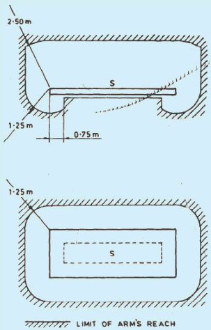
NOTE — This space is by convention, limited as shown in Fig. 1.
Fig. 1 Limit of Arm’s Reach
3.4.4 Barrier — A part providing protection against direct contact from any usual direction of access
3.4.5 Basin of Fountain — A basin not intended to be occupied by persons and which cannot be accessed (reached by persons) without the use of ladders or similar means. For basins of fountains which may be occupied by persons, the requirement of swimming pools applies.
3.4.6 Booth — Non-stationary unit intended to accommodate equipment generally for pleasure or demonstration purpose.
3.4.7 Building — Any structure for whatsoever purpose and of whatsoever materials constructed and every part thereof whether used as human habitation or not and includes foundation, plinth, walls, floors, roofs, chimneys, plumbing and building services, fixed platforms, verandah, balcony, cornice or projection, part of a building or anything affixed thereto or any wall enclosing or intended to enclose any land or space and signs and outdoor display structures. Tents, shamianahs, tarpaulin shelters, etc, erected for temporary of the Authority shall not be considered as building.
3.4.8 Building Voids, Accessible — Space within the structure or the components of a building accessible only at certain points.
NOTE — Examples are space within partitions, suspended floors, ceilings and certain types of window frames, door frames and architraves A specially formed building void in an element of building is also known as a duct.
3.4.9 Building Void, Non-accessible — A space within the structure or the components of building which has no ready means of access.
3.4.10 Clearance — The distance between two conducting parts along a string stretched the shortest way between these conducting parts.
3.4.11 Competent Person — A person who can judge the work assigned and recognize possible hazards on the basis of professional training, knowledge, experience and knowledge of the relevant equipment.
3.4.12 Connected Load — That part of the installed load of the consumer that may be supplied by the supply undertaking.
3.4.13 Consumer or Customer — The party who receives electricity from the supply or distribution undertaking.
3.4.14 Continuous Operating Voltage (Uc) — Maximum rms voltage which may be continuously applied to an SPD’s mode of protection. This is equal to rated voltage.
3.4.15 Conventional Impulse Withstand Voltage — The peak value of an impulse test voltage at which insulation does not show any disruptive discharge, when subjected to a specified number of applications of impulses of this value, under specified condition.
NOTE — Standard impulse wave of 1.2/50 µs shall be used.
3.4.16 Conventional Touch Voltage Limit — Maximum value of the prospective touch voltage which is permitted to be maintained indefinitely in specified conditions of external influences.
3.4.17 Conventional Operating Current (of a Protective Device) — Specified value of the electric current intended to cause the protective device to operate within a specified duration.
NOTES
1 For fuses this current is called the conventional fusing current. For circuit breakers this current is called the conventional operating current.
19
2 The conventional operating current is greater than the rated current or current setting of the device and the conventional time varies according to the type and rated current of the protective device.
3.4.18 Creepage Distance — Shortest distance or the sum of the shortest distances along the surface on an insulator between two conductive parts which normally have the operating voltage between them.
NOTES
1 The surface of cement or of any other non-insulating jointing material is not considered as forming part of the creepage distance.
2 If a high resistance coating is applied to parts of the insulating part of an insulator, such parts are considered to be effective insulating surfaces and the distance over them is included in the creepage distance.
3.4.19 Impulse — Usually an aperiodic transient voltage or current which rises rapidly to a peak value and then falls, generally more slowly, to zero. Ideally, it approximates a double exponential form. Other forms are sometimes used for special purposes
3.4.20 Current Carrying Capacity of a Conductor — The maximum current which can be carried by a conductor under specified conditions without its steady state temperature exceeding a specified value.
3.4.21 Danger — Risk of electrical injury when electrical energy is present in an electrical installation
3.4.22 Demand — The magnitude of electricity supply, expressed in kW or kVA
3.4.23 Design Current (of a Circuit) — The magnitude of the current intended to be carried by the circuit in normal service.
3.4.24 Distribution Undertaking — The party supplying electricity to consumers entirely from external sources of power via a distribution network.
3.4.25 Domestic Tariff — A tariff applicable particularly or exclusively to domestic consumers.
3.4.26 Earth Fault Current — Current flowing to earth due to an insulation fault.
3.4.27 Earth Electrode Resistance — The resistance of an earth electrode to earth.
3.4.28 Earth Fault Loop Impedance — The impedance of the earth fault current loop (phase to earth loop) starting and ending at the point of earth fault. This impedance is denoted by the symbol Z. The earth fault loop comprises the following, starting at the point of fault:
a) the circuit protective conductor;
b) the consumer’s earthing terminal and earthing conductor, and for TN systems, the metallic return path;
c) for TT and IT systems, the earth return path;
d) the path through the earth neutral point of the transformer;
e) the transformer winding; and
f) the line conductor from the transformer to the point of fault.
3.4.29 Earth Leakage Current — Current flowing from the live parts of the installation to earth, in the absence of an insulation fault.
3.4.30 Earthing Resistance, Total — The resistance between the main earthing terminal and the conductive mass of earth.
3.4.31 Enclosure — Housing affording the type and degree of protection suitable for the intended application.
3.4.32 Fault Current — Current which flows across a given point of fault resulting from an insulation failure.
3.4.33 Fault Protection — Protection against electric shock under single fault conditions.
NOTE — For low voltage installation, systems and equipment, fault protection generally corresponds to protection against in direct contact, mainly with regards to failure of basic insulation. Indirect contact is “contact of persons or livestock with exposed- conductive parts which have become live under fault conditions.”
3.4.34 Final Circuit — Electric circuit intended to supply directly electric current to current using equipment or socket-outlets.
3.4.35 Hazardous-Live Part — Live part which, under certain conditions, can give a harmful electric shock
3.4.36 Heating Tariff — A tariff applicable to electricity supplies taken for space heating or for other heating applications.
3.4.37 Impulse Current — A parameter used for the classification test for SPDs; it is defined by three elements, a current peak value, a charge Q and a specific energy W/R.
3.4.38 Impulse Withstand Voltage — The highest peak value of impulse voltage of prescribed form and polarity which does not cause breakdown of insulation under specified condition.
3.4.39 Installed Load — The sum of the nameplate ratings of the electrical apparatus installed on the consumer’s premises.
3.4.40 Kilo watthour Rate (kWh Rate) — The amount to be paid per unit of energy (kWh) consumed.
3.4.41 Industrial Tariff — A tariff applicable particularly or exclusively to industrial consumers.
3.4.42 Leakage Current — electric current in an unwanted conductive path under normal operating conditions.
NOTE — This current may have a capacitive component including that resulting from the deliberate use of capacitors.
3.4.43 Lighting Protection Zone — Zone where the lightning electromagnetic environment is defined.
3.4.44 Lighting Tariff — A tariff applicable to electricity supplies taken mainly for lighting.
3.4.45 Line Conductor — Conductor which is energized in normal operation and capable of contributing to the transmission or distribution of electric energy but which is not a neutral or mid-point conductor.
3.4.46 Live Part — Conductor or conductive part intended to be energized in normal operation, including a neutral conductor, but by convention not a PEN conductor or PEM conductor or PEL conductor
NOTE — This concept does not necessarily imply a risk of electric shock.
3.4.47 Load Factor — The ratio, expressed as a numerical value or as a percentage, of the consumption within a specified period (year, month, day, etc.), to the consumption that would result from continuous use of the maximum or other specified demand occurring within the same period.
NOTES
1 This term should not be used without specifying the demand and the period to which it relates.
2 The load factor for a given demand is also equal to the ratio of the utilization time to the time in hours within the same period.
3.4.48 Meter Rent — An amount to be paid for a specified period for metering, and allied equipment installed.
3.4.49 Monitoring — Observation of the operation of a system or part of a system to verify correct functioning or detect incorrect functioning by measuring system variables and comparing the measured value with the specified value.
3.4.50 Nominal Voltage (of an Installation) — Value of the voltage by which the electrical installation or part of the electrical installation is designated and identified.
NOTE — The actual voltage may differ from the nominal voltage by a quantity within permitted tolerances.
3.4.51 Obstacle — Part preventing unintentional direct contact, but not preventing direct contact by deliberate action.
3.4.52 Occupancy or Use Group — The principal occupancy for which a building or a part of a building is used or intended to be used; for the purposes of classification of a building according to occupancy, an occupancy shall be deemed to include the subsidiary occupancies which are contingent upon it.
3.4.53 Overcurrent — A current exceeding the rated value. For conductors the rated value is the current carrying capacity.
3.4.54 Overcurrent Detection — A method of establishing that the value of current in a circuit exceeds a predetermined value for a specified length of time.
3.4.55 Overload Current (of a Circuit) — Overcurrent occurring in an electric circuit, which is not caused by a short-circuit or an earth fault.
3.4.56 Power Factor Clause — A price adjustment clause setting out the charges which apply according to the level of power factor or to the magnitude of reactive energy consumption.
NOTE — The power factor is generally measured by the ratio of kWh to kVAh consumed during the specified period.
3.4.57 Prospective Fault Current (Ipf) — The value of fault current at a given point in a circuit resulting from a fault of negligible impedance between live conductor having a difference of potential under normal operating conditions, or between a live conductor and an exposed conductive part.
3.4.58 Prospective Touch Voltage — Voltage between simultaneously accessible conductive parts when those conductive parts are not being touched by a person or an animal.
3.4.59 Protective Conductor Current — Electric current appearing in a protective conductor, such as leakage current or electric current resulting from an insulation fault.
3.4.60 Rated Current — Value of current in accordance with which the relevant performance of a transformer operated meter is fixed.
3.4.61 Rated Impulse Withstand Voltage Level (Uw) — Impulse withstand voltage: highest peak value of impulse voltage of prescribed form and polarity which does not cause breakdown of insulation under specified conditions
3.4.62 Residual Current — Algebraic sum of the values of the electric currents in all live conductors, at the same time at a given point of an electric circuit in an electrical installation.
3.4.63 Residual Operating Current — Value of residual current which causes the residual current device to operate under specified conditions
3.4.64 Room Height — The vertical distance measured from the finished floor surface to the finished ceiling surface. The underside of the joints or beams or tie beams shall determine the upper point of measurement for determining the head room.
3.4.65 Service Line, Service — A line for connecting a current consuming installation to the distribution network.
21
3.4.66 Shock Current — A current passing through the body of a person or an animal and having characteristics likely to cause dangerous patho-physiological effects.
3.4.67 Short-Circuit Current — An overcurrent resulting from a fault of negligible impedance between live conductors having a difference in potential under normal operating conditions.
3.4.68 Simultaneously Accessible Parts — Conductors or conductive parts which can be touched simultaneously by a person or by an animal.
NOTE — Simultaneously accessible parts may be:
a) live parts;
b) exposed-conductive-parts;
c) extraneous-conductive-parts;
d) protective conductors; and
e) soil or conductive floor.
3.4.69 Skilled Person — A person who can judge the work assigned and recognize possible hazards on the basis of professional training, knowledge, experience and knowledge of the relevant equipment.
3.4.70 Supply Terminals — The point at which a consumer receives energy.
3.4.71 Surge Current — A transient wave appearing as an overcurrent caused by a lightning electromagnetic impulse.
3.4.72 Tariff — A statement setting out the components to be taken into account and the methods to be employed in calculating the amounts to be paid to the supply undertaking by the consumer, according to the characteristics of the supply.
3.4.73 Temporary Overvoltage ( U T O V ) — Power frequency overvoltage of relatively long duration.
NOTES
1 A temporary overvoltage is undamped or weakly damped. In some cases its frequency may be several times smaller or greater than power frequency.
2 TOVs may be caused by faults in the LV system or in the HV system.
3 Temporary overvoltages, typically, lasting up to several seconds, usually originate from switching operations or faults (for example, sudden load rejection, single-phase faults, etc.) and/or from non-linearity (ferro resonance effects, harmonics, etc).
3.4.74 Touch Voltage — Voltage between conductive parts when touched simultaneously by a person or an animal. NOTE — The value of the effective touch voltage may be appreciably influenced by the impedance of the person or the animal in electric contact with these conductive parts.
| IS No./International Standard | Title |
|---|---|
| 732 : 2019 | Code of practice for electrical wiring installations |
| 1885 (Part 1) : 1961 | Electrotechnical vocabulary — Part 1 Fundamental definitions |
| 1885 (Part 9) : 1992/IEC 60050-446 : 1983 | Electrotechnical vocabulary — Part 9 Electrical relays (second revision) |
| 1885 (Part 10) : 2008/IEC 60050 (448) : 1995 | Electrotechnical vocabulary — Part 10 Power system protection (second revision) |
| 1885 (Part 11) : 1966 | Electrotechnical vocabulary — Part 11 Electrical measurements |
| 1885 (Part 14) : 1967 | Electrotechnical vocabulary — Part 14 nuclear power plants |
| 1885 (Part 15) : 2008/IEC 60050-482 : 2004 | Electrotechnical vocabulary — Part 15 Primary and secondary cells and batteries (second revision) |
| 1885 (Part 16/Sec 1) : 1968/IEC 60050-45 : 1958 | Electrotechnical vocabulary — Part 16 Lighting — Section 1 General aspects |
| 1885 (Part 16/Sec 2) : 1968/IEC 60050-45 : 1958 | Electrotechnical vocabulary — Part 16 Lighting — Section 2 General illumination, lighting fittings and lighting for traffic and signalling |
| 1885 (Part 16/Sec 3) : 1967/IEC 60050-54 | Electrotechnical vocabulary — Part 16 Lighting — Section 3 Lamps and auxiliary apparatus |
| 1885 (Part 17) : 1979/IEC 60050-441 : 1974 | Electrotechnical vocabulary — Part 17 Switchgear and control gear (first revision) |
| 1885 (Part 27) : 2008/IEC 60050-551 : 1998 | Electrotechnical vocabulary — Part 27 Power electronics (third revision) |
| 1885 (Part 28) : 1993/IEC 60050-321 : 1986 | Electrotechnical vocabulary — Part 28 Instrument transformers (first revision) |
| 1885 (Part 29) : 1971 | Electrotechnical vocabulary — Part 29 Mining terms |
| 1885 (Part 30) : 1971 | Electrotechnical vocabulary — Part 30 Overhead transmission and distribution of electrical energy |
| 1885 (Part 32) : 2019/IEC 60050-461 : 2008 | Electrotechnical vocabulary — Part 32 Electric cables (second revision) |
| 1885 (Part 34) : 1972 | Electrotechnical vocabulary — Part 34 Cinematography |
| 1885 (Part 35) : 2021/IEC 60050-411 : 1996 | Electrotechnical vocabulary — Part 35 Rotating machinery (second revision) |
| 1885 (Part 37) : 1993/IEC 60050-691 : 1973 | Electrotechnical vocabulary — Part 37 Tariffs for electricity (first revision) |
| 1885 (Part 38) : 1993/IEC 60050-421 : 1990 | Electrotechnical vocabulary — Part 38 Power transformers and reactors (second revision) |
| 1885 (Part 43) : 1977 | Electrotechnical vocabulary — Part 43 Electrical equipment used in medical practice |
| 1885 (Part 51) : 2012/IEC 60050-841 : 2004 | Electrotechnical vocabulary — Part 51 Industrial electroheat (second revision) |
| 1885 (Part 53) : 1980 | Electrotechnical vocabulary — Part 53 Mica |
| 1885 (Part 54) : 2021/IEC 60050-471 : 2015 | Electrotechnical vocabulary — Part 54 Insulators |
| IS No./International Standard | Title |
|---|---|
| 1885 (Part 55) : 1981 | Electrotechnical vocabulary — Part 55 Electric fans |
| 1885 (Part 57) : 2008/IEC 60050-131 : 2002 | Electrotechnical vocabulary — Part 57 Circuit theory (second revision) |
| 1885 (Part 60) : 1993/IEC 60050-426 : 1990 | Electrotechnical vocabulary — Part 60 Electrical apparatus for explosive atmospheres (first revision) |
| 1885 (Part 61) : 1985 | Electrotechnical vocabulary — Part 61 Nuclear medical instruments |
| 1885 (Part 62) : 2021/IEC 60050-212 : 2010 | Electrotechnical vocabulary — Part 62 Electrical insulating solids liquids and gases (second revision) |
| 1885 (Part 69) : 1993/IEC 60050-602 : 1993 | Electrotechnical vocabulary — Part 69 Generation, transmission and distribution of electricity — Generation |
| 1885 (Part 70) : 1993/IEC 60050-604 : 1987 | Electrotechnical vocabulary: Part 70 Generation, transmission and distribution of electricity — Operation |
| 1885 (Part 71) : 1993/IEC 60050-605 : 1983 | Electrotechnical vocabulary — Part 71 Generation, transmission and distribution of electricity — Substations |
| 1885 (Part 72) : 2008/IEC 60050-101 : 1998 | Electrotechnical vocabulary — Part 72 Mathematics (first revision) |
| 1885 (Part 73) : 2012/IEC 60050-111 : 1996 | Electrotechnical vocabulary — Part 73 Physics and chemistry (first revision) |
| 1885 (Part 74) : 2012/IEC 60050-151 : 2001 | Electrotechnical vocabulary — Part 74 Electrical and magnetic devices (first revision) |
| 1885 (Part 75) : 2012/IEC 60050-351 : 2006 | Electrotechnical vocabulary — Part 75 Control technology (first revision) |
| 1885 (Part 77) : 1993/IEC 60050-466 : 1990 | Electrotechnical vocabulary — Part 77 Overhead lines |
| 1885 (Part 78) : 1993/IEC 60050-601 : 1985 | Electrotechnical vocabulary — Part 78 Generation, transmission and distribution of electricity — General |
| 1885 (Part 79) : 1993/IEC 60050-603 : 1986 | Electrotechnical vocabulary — Part 79 Generation, transmission and distribution of electricity — Power system planning and management |
| 1885 (Part 80) : 1994/IEC 60050-301 : 1983 | Electrotechnical vocabulary — Part 80 General terms on measurements in electricity |
| 1885 (Part 81) : 1993/IEC 60050-302 : 1983 | Electrotechnical vocabulary — Part 81 Electrical measuring instruments |
| 12360 : 1988 | Voltage bands for electrical installations including preferred voltages and frequency |
SP 30 : 2023
Several graphical symbols are used for installation diagrams. Considerable amount of standardization has been achieved in the field of symbols for electrotechnology. It is now possible to devise electrical network schematics using them so that these schematic diagrams could be uniformly understood by all concerned.
Assistance has also been derived from IS 12032 (all parts).
This section of the code (Part 1/Sec 3) covers graphical symbols for diagrams, letter symbols and signs.
The standards listed in Annex A contain provisions, which through reference in this text, constitute provisions of this standard. At the time of publication, the editions indicated were valid. All standards are subject to revision, and parties to agreements based on this standard are encouraged to investigate the possibility of applying the most recent editions of the standards.
For the purposes of the Code, the graphical symbols given below shall apply.
3.1.1 Direct Current
a) Alternating current, single-phase, 50 Hz 2 50 HZ
b) Alternating current, three-phase at 415 V, 50 Hz 50Hz, 3 415V
c) Alternating current, three-phase with neutral at 50 Hz 3NI 50Hz
3.1.3 Neutral

3.1.4 Positive Polarity

3.1.5 Negative Polarity
3.1.6 Direct Current, two Conductors at 110 V 2 110V
3.1.7 Direct Current, three Conductors including Negative at 220 V 2N 220V
3.1.8 Underground Cable
3.1.9 Overhead Line


3.1.10 Winding, Delta

3.1.11 Winding, Star
3.1.12 Terminals Q
3.1.13 Resistance/Resistor
3.1.13.1 Variable resistor

--
3.1.14 Impedance 2
3.1.15 Inductance/Inductor LHUT
3.1.16 Winding

3.1.17 Capacitance, Capacitor
4.0.1 Quantities and units in electrotechnology, in addition to electricity and magnetism, covers other subjects, such as radiation and light, geometry, kinematics, dynamics and thermodynamics. Several disciplines interact with each other such that terminology used in one discipline becomes closely interrelated with that of the other. In order to enable uniform understanding and representation, the letter symbols and signs used in abbreviations for denoting quantities, their functions and units shall conform to those recommended in IS 3722 (Part 1) and IS 3722 (Part 2).
4.0.2 Guidance on the choice of alphabet and their type, representation of vector quantities, symbols of units, numerical values, and guidance on the use of subscripts are covered in IS 3722 (Part 1).
4.0.3 Table 1 of IS 3722 (Part 2) gives a reference list of symbols and subscripts used in electrotechnology.
| IS/Other Publications | Title |
|---|---|
| 2032 (Part 19) : 1977 | Graphical symbols used in electrotechnology: Part 19 Electrical equipment used in medical practice |
| 3722 (Part 1) : 1983 | Letter symbols and signs used in electrical technology: Part 1 General guidance on symbols and subscripts (first revision) |
| 3722 (Part 2) : 1983 | Letter symbols and signs used in electrical technology: Part 2 Reference tables for symbols and subscripts (first revision) |
| 10381 : 1982 | Terms (and their hindi equivalents) commonly used for name — Plates and similar data of electrical power equipment |
| 11353 : 1985 | Guide for uniform system of marking and identification of conductors and apparatus terminals |
| 12032 (Part 1) : 1987/IEC 60617-1 (1985) | Graphical symbols for diagrams in the field of electrotechnology: Part 1 General information |
| 12032 (Part 2) : 1987/IEC 60617-2 (1983) | Graphical symbols for diagrams in the field of electrotechnology: Part 2 Symbol elements, qualifying symbols and other symbols having general application |
| 12032 (Part 3):1987/IEC 60617-3 : 1983 | Graphical symbols for diagrams in the field of electrotechnology: Part 3 conductors and connecting devices |
| 12032 (Part 4) : 1987/IEC 60617-4 (1984) | Graphical symbols for diagrams in the field of electrotechnology: Part 4 Passive components |
| 12032 (Part 6) : 1987/IEC 60617-6 (1983) | Graphical symbols for diagrams in the field of electrotechnology: Part 6 Production and conversion of electrical energy |
| 12032 (Part 7) : 1987/IEC 60617-7 (1983) | Graphical symbols for diagrams in the field of electrotechnology: Part 7 Switchgear, controlgear and protective devices |
| 12032 (Part 8) : 1987/IEC 60617-8 (1983) | Graphical symbols for diagrams in the field of electrotechnology: Part 8 Measuring instruments, lamps and signalling devices |
| 12032 (Part 11) : 1987/IEC 60617-11 (1983) | Graphical symbols for diagrams in the field of electrotechnology: Part 11 Architectural and topographical installation plan and diagrams |
Various types of diagrams and charts are required to be prepared during the planning and execution stages of an electrical installation work. It is therefore necessary to define the different types of diagrams, charts and tables, their purposes and format and the guiding principles for preparing them for maintaning uniformity.
This section of the Code covers general guidelines on the preparation of diagrams, charts, tables and marking.
The guidelines for marking of conductors is given in 3.6. It provides a common basis for understanding and identifying conductors and apparatus terminals, but more importantly, ensure safety to operating and maintenance personnel.
This section of the code (Part 1/Sec 4) covers guidelines for preparation of diagrams, charts and tables in electrotechnology and for marking of conductors.
The standards listed in Annex A contain provisions, which through reference in this text, constitute provisions of this standard. At the time of publication, the editions indicated were valid. All standards are subject to revision, and parties to agreements based on this standard are encouraged to investigate the possibility of applying the most recent editions of the standards.
A diagram may show the manner in which the various parts of a network, installation, group of apparatus or items of an apparatus are interrelated and or interconnected.
A chart may show the interrelation between:
a) different operations,
b) operations and time,
c) operations and physical quantities, and
d) states of several items.
A table replaces or supplements a diagram or a chart.
The main classifications are:
a) Explanatory diagrams,
b) Explanatory charts or tables,
c) Wiring diagrams or wiring tables, and
d) Location diagrams or tables.
Explanatory diagrams are intended to facilitate the study and understanding of the functioning of an installation or equipment. Three types are defined as under:
SP 30 : 2023
Relatively simple diagram to facilitate the understanding of the principle of operation. It is a diagram in which an installation or equipment together with its functional interrelationships are represented by symbols, block symbols or pictures without necessarily showing all the connections.
Explanatory diagram intended to facilitate the understanding of the functioning in detail. It shows by symbols an installation or part of an installation and the electrical connections and other links concerned with its operation.
c) Equivalent Circuit Diagram
Special type of circuit diagram for the analysis and calculation of circuit characteristics.
Explanatory charts or tables are intended to facilitate the study of diagrams and to give additional information. Examples are given as under:
a) Sequence Chart or Table
Gives the successive operation in a specified order.
b) Time Sequence Chart or Table
Is one which in addition takes account of the time intervals between successive operations.
Wiring diagrams are intended to guide the making and checking of the connection of an installation or equipment. For an equipment, they show the internal or external connections or both. The diagrams may sometimes show the layout of the different parts and accessories, such as terminal blocks and the wiring between them.
Diagram represents all connections within a unit of an installation.
Diagram represens the connections between the different units of an installation.
Diagram showing the terminals and the internal and/or external conductors connected to them.
NOTE — Any of the wiring diagram may be replaced or supplemented by a table.
A location diagram or table contains detailed information about the location of parts of the equipment (for example, terminal blocks, plug-in units, sub-assemblies, modules, etc.). It shows the item designations used in related diagrams and tables.
3.2.1 The method of representation is distinguished by the:
a) number of conductors, devices or elements represented by a single symbol (see 3.2.1.1);
b) arrangement of the symbols representing the elements or parts of an item of apparatus (for example, detached or assembled) (see 3.2.1.2); and
c) placing of the symbols to correspond with the topographical layout of the devices (see 3.2.1.3).
According to the number of conductors, devices or elements represented by a single symbol, the two methods of representation as given below may be distinguished.
Two or more conductors are represented by a single line.
In particular, a single line may represent:
circuits of a multi-phase system;
circuits which have a similar electrical function;
circuits or conductors which belong to the same signal path;
circuits which follow the same physical route; and
conductor symbols which would follow the same route on the diagram.
Several similar items of apparatus may accordingly, be represented by a single symbol.
Each conductor is represented by an individual line.
According to the arrangement of the symbols representing the elements or parts of an item of apparatus on the diagram, the methods of representation are given below:
The symbols for the different parts of an item of apparatus or of an installation or equipment are drawn in close proximity on the diagram.
The symbols for the different parts of an item of apparatus or of an installation are separated and arranged in such a way that the symbols for mechanical linkages between the parts which work together may be drawn easily.
The symbols for the different parts of an item of apparatus or of an installation are separated and arranged in such a way that the circuits may easily be followed.
The positions of the symbols on the diagram correspond wholly or partly to the topographical (physical) location of items represented.
The following are examples where topographical representation may be used.
a) Wiring diagrams;
3.3.1 Item is a term used for component equipment, plant, unit, etc, which is represented by a graphical symbol on a diagram. The item designation is shown at an appropriate place near the graphical symbol of the item. This designation correlates the item on different diagrams, parts list, circuit descriptions and components in the equipment.
3.3.2 An item designation may be used for general or special purposes depending on the kind of information required. Guidelines on assignment of item designation, groups together with standard letter codes for the same are covered in IS 8270 (Part 2), IEC 81346-1 and IEC 81346-2.
3.4.1 Paper sizes for drawings shall preferably be according to the international A-series (see IS 1064). The choice of drawing sizes should be decided after taking into account the necessary factors enumerated in 2.2 of IS 8270 (Part 2).
3.4.2 In IS 2032 series of standards and IS 12032 series of standards, different kinds of symbols as well as symbols of different forms are specified to the extent possible. Any symbol may be composed using the guidance from IS 2032 and Part 1/Sec 3 of the Code, IEC 60417 and ISO 7000. The basic rules for the choice of symbols shall be:
a) to use the simplest form of symbol adequate for the particular purpose;
SP 30 : 2023
b) to use a preferred form wherever possible; and
c) to use the chosen form consistently throughout the same set of documentation.
3.4.3 Specific guidelines on the application of IS 2032 series of standards, IS 12032 series of standards, IEC 60417 and ISO 7000 with the objective of selection of choice of alternative symbols, symbol sizes, line thickness, orientation of symbols and methods of indicating symbol location are covered in IS 8270 (Part 3).
3.5.1 Interconnection diagrams and tables provide information on the external electrical connections between equipment in an installation. They are used as an aid in the fabrication of wiring and for maintenance purposes. Information on the internal connections of units are normally not provided but references to the appropriate circuit diagram [see IS 8270 (Part 4)] may be provided.
3.5.2 The diagrams may employ single or multiple representation and may be combined with or replaced by tables, provided clarity is maintained. Tables are recommended when the number of interconnections is large.
3.5.3 Guidance on layout, identification and types of interconnection diagrams and tables are given in IS 8270 (Part 5).
3.6.0.1 The purpose of marking is to provide a means whereby conductors can be identified in a circuit and also, after they have been detached from the terminals to which they are connected. Main marking is a system of marking characterizing each conductor or group of conductors irrespective of their electrical function. Supplementary marking is used as supplement to a main marking based on the electrical function of each conductor or group of conductors.
3.6.0.2 The various methods of marking applicable to electrical installations and the equipment which form part of them are covered in IS 5578.
For the purposes of this Code, the provisions of Table 1 of IS 11353 shall apply for the general application of marking conductors in installation. The rules also apply for marking conductors in assembles, equipment and apparatus. Reference is also drawn to the provision contained in relevant Indian Standard.
Bus-bars and main connections which are substantially in one plane shall be arranged in the order given in 3.6.2.1 or 3.6.2.2 according to the system. The relative order remains applicable even if any poles of the system are omitted.
The order of phase connection shall be red, yellow and blue:
a) When the run of the conductors is horizontal, the red shall be on the top or farthest away as viewed from the front.
b) When the run of the conductors is vertical, the red shall be on the left or farthest away as viewed from the front.
c) When the system has a neutral connection in the same place as the phase connections, the neutral shall occupy an outer position.
d) Unless the neutral connection can be readily distinguished from the phase connections, the order shall be red, yellow, blue and black.
The order of arrangement shall be positive, mid-point (if available) and negative:
a) When the run of the conductors is horizontal, the positive shall be on the top or farthest away as viewed from the front.
b) When the run of the conductors is vertical, the positive shall be on the left or farthest away as viewed from the front.
c) When the system is three-wire system with the conductors in the same place, the neutral (mid-wire) shall occupy the middle position.
| IS/Other Publications | Title |
|---|---|
| 1064 : 1980 | Specification for paper (second revision) |
| 2032 (Part 15) : 1976 | Graphical symbols used in electrotechnology — Part 15 Aircraft electrical symbols |
| 2032 (Part 19) : 1977 | Graphical symbols used in electrotechnology — Part 19 Electrical equipment used in medical practice |
| 2032 (Part 25) : 1980 | Graphical symbols used in electrotechnology — Part 25 Electrical installations in ships |
| 5578 : 1984 | Guide for marking of insulated conductors (first revision) |
| 8270 (Part 1) : 1976 | Guide for preparation of diagrams, charts and tables for electrotechnology — Part 1 Definitions and classification |
| 8270 (Part 2) : 1976 | Guide — For preparation of diagrams, charts and tables for electrotechnology — Part 2 Item designation |
| 8270 (Part 3) : 1977 | Guide for preparation of diagrams, charts and tables for electrotechnology — Part 3 General requirements for diagrams |
| 8270 (Part 4) : 1977 | Guide for preparation of diagrams, charts and tables for electrotechnology — Part 4 Circuit diagrams |
| 8270 (Part 5) : 1976 | Guide for preparation of diagrams, charts and tables for electrotechnology — Part 5 Interconnection diagrams and tables |
| 8270 (Part 6) : 1983 | Guide for preparation of diagrams, charts and tables for electrotechnology — Part 6 Unit wiring diagrams and tables |
| 11353 : 1985 | Guide for uniform system of marking and identification of conductors and apparatus terminals |
| IEC 60417 DB | Graphical symbols for use on equipment |
| IEC 81346-1 : 2009 | Industrial systems, installations and equipment and industrial products — Structuring principles and reference designations — Part 1 Basic rules |
| IEC 81346-2 : 2019 | Industrial systems, installations and equipment and industrial products — Structuring principles and reference designations — Part 2 Classification of objects and codes for classes |
SP 30 : 2023
The International System of Units (SI) have received worldwide acceptance and is accepted in most of the countries. It had been introduced in India under the Weights and Measures Act, 1976. Use of SI Units in matters relating to electrical engineering practice has many advantages.
This Section of the Code is restricted to electrical units only.
This Section of the Code (Part 1/Sec 5) covers units and systems of measurement in electrotechnology.
The standards contain provisions, which through reference in this text, constitute provisions of this standard. At the time of publication, the edition indicated were valid. All standards are subject to revision, and parties to agreements based on this standard are encouraged to investigate the possibility of applying the most recent editions of the standards.
IS/Other Publications
Title
IS/ISO 80000-2 : 2009
Quantities and units — Mathematical signs and symbols to be used in the natural sciences and technology
SI unit of electric current, equal to the electric current corresponding to the flow of (1/1.602 176 634) × 1019 elementry electric charges per second.
The quantity of electricity conveyed in one second by a current of one ampere.
The capacitance of an electric capacitor having a difference of electric potential of one volt between the plates, when it is charged with a quantity of electricity of one coulomb.
The inductance of a closed circuit in which an emf of one volt is produced when the current in the circuits varies at the uniform rate of one ampere per second.
The electrical resistance between two points of a conductor when a constant potential difference of one volt, applied to these points, produces a current of one ampere in the conductor, provided no emf is generated in the conductor.
The difference of electric potential which exists between two points of a conductor carrying a constant current of one ampere, when the power dissipated between these points is one watt.
The magnetic flux which, linked with a circuit composed of a single turn produces in it an emf of one volt if it is uniformly reduced to zero in one second.
The power which results in the production of energy at the rate of 1 J/s.
3.1.9 Siemens (Unit of Electric Conductance)
The conductance of a conductor of resistance 1 ohm and is numerically equal to 1 ohm-1.
3.1.10 Tesla
The tesla is a magnetic flux density of 1 Wb/m2.
3.2 The electrical units defined in 3.1, together with their expression in terms of other units, recommendations on the selection of their multiples and submultiples and supplementary remarks (if any) are enumerated in Table 1.
Table 1 Electrical Units of Measurement
(Clause 3.2)
| Sl No. | Quantity | Name | Symbol | Expression in Terms of Other Units |
|---|
Standardization of basic parameters, such as voltage, currents and frequency is a pre-requisite to laying a sound foundation for further work relating to product or installation engineering. The values of basic parameters recommended in this section are based on IS 12360.
Reference to CEA (Safety) Regulations, 2010 may also be made.
This section of the Code (Part 1/Sec 6) covers standard values of a.c. and d.c. distribution voltages, preferred values of current ratings and standard system frequency.
IS No
Title
1076 (Part 1) : 1985/
ISO 3 : 1973
Preferred numbers: Part 1 Series of preferred numbers
12360 : 1988 Voltage bands for electrical installations including preferred voltages and frequency
16711 : 2017 48 V ELVDC Distribution System — Guidelines
3.0.1 Standard values of voltages as mentioned in IS 12360 relating to a.c. transmission and distribution systems are reproduced in this section. However, it may be noted that for types of installations covered in subsequent parts of the Code, lower voltage values would be more relevant.
3.0.2 For medium and low voltage of distribution system, nominal voltages were 230 V for single-phase and 230/400 V for three-phase system were the recommended standard values. Later on, to align with IEC recommendations and in view of the economic advantages, nominal values of 240 V for single-phase and 240/415 V for three-phase were adopted with a tolerance of ± 6 percent. IS 12360 may be referred for the latest values.
3.0.3 In the case of voltages above 1 kV, product standards relate the voltage rating of equipment with respect to highest system voltages (generally, 10% above the nominal voltage).
3.1.1 Single-phase, Two-wire System
The standard voltage shall be as per IS 12360.
3.1.2.1 The standard voltages for three-phase system shall be as per IS 12360.
3.1.3 As per the international standards, the direct current (d.c.) of 60V is established as the upper limit for a Safety Extra Low Voltage circuit (SELV), that is, safe to touch directly under dry conditions. Considering both safety and distribution losses, 48V is chosen as the distribution voltage for d.c.
3.1.4 For ELVDC and LVDC, IS 16711 may be referred.
3.2.1 The voltage at any point of the system under normal conditions shall not depart from the declared voltage by more than the values given below:
a) 6 percent in the case of low or medium voltage;
NOTE — IS 12360 may be referred for the latest provisions.
b) 6 percent on the higher side or 9 percent on the lower side in the case of high voltage; or
c) 12.5 percent in the case of extra high voltage.
NOTE — The permissible variations given above are in accordance with CEA (Safety) Regulations, 2010, and are applicable to the supply authorities.
3.2.2 For installation design purposes, the limits of voltage between which the system and the equipment used in the system shall be capable of operating continuously are as follows:
| System Voltage (Un) | Highest Voltage (Um) | Lowest Voltage |
| (1) | (2) | (3) |
| 240 V | 264 V | 216 V |
| 415 V | 457 V | 374 V |
| 3.3 kV | 3.6 kV | 3.0 kV |
| 6.6 kV | 7.2 kV | 6.0 kV |
| 11 kV | 12 kV | 10 kV |
| 22 kV | 24 kV | 20 kV |
| 33 kV | 36 kV | 30 kV |
| 66 kV | 72.5 kV | 60 kV |
| 132 kV | 145 kV | 120 kV |
| 220 kV | 245 kV | 200 kV |
| 400 kV | 420 kV | 380 kV |
| NOTES | ||
| 1 This variation in voltage should not be confused with the permissible variation from the declared voltage as given in 3.2.1. | ||
| 2 IS 12360 may be referred for the latest provisions | ||
5.2 The limits within which the frequency shall be maintained are governed by the CEA (Safety) Regulations, 2010.
SP 30 : 2023
The basic criteria in the design of electrical installation are enumerated in this section which shall be adhered to during the planning stages. The specific nature of each occupancy calls for additional information, which are summarized in the respective sections of the Code.
Considerable assistance has been derived from IS 732. It may be noted that subsequent requirements of the Code would, however, provide adequate guidelines in respect of achieving the desired levels of specific planning, work execution, workmanship and safety.
This Section of the Code (Part 1/Sec 7) enumerates the fundamental principles of design and execution of electrical installations.
The standards listed below contain provisions, which through reference in this text, constitute provisions of this standard. At the time of publication, the editions indicated were valid. All standards are subject to revision, and parties to agreements based on this standard are encouraged to investigate the possibility of applying the most recent editions of the standards:
IS/Other Publications Title
SP 7 : 2016 National Building Code of India
SP 72 : 2010 National Lighting Code
CEA Regulations Central Electricity Authority (measures related to Safety and Electric Supply) Regulations, 2010
Central Electricity Authority (Technical Standards for Construction of Electrical Plants and Electric Lines) Regulations, 2010
Central Electricity Authority (Safety Requirements for Construction, Operation and Maintenance of Electric Plants and Lines) Regulations, 2011
For any electrical installation to be safe, functional, easy to use, augmentable, prone to minimal breakdowns requiring zero or minimum down time and conforming to all Statutory Provisions. Electrical Installation as part of Building Service, design shall be based on fundamental principles as given under this section. Consideration shall also be given to related recommendations under National Building Code.
Under environmental and energy conservation aspects, all related provisions shall be considered under fundamental principles, comprising of natural light, ventilation, thermal insulation, solar systems etc.
It is an initial important step which helps the work to get completed smoothly and in time with minimum changes and reworking and without conflicts with the work of other utility services.
Proper coordination and collaboration between the user, architect, civil and electrical engineer, suppliers of electricity, water, telephone, cable/internet etc. shall be ensured from the planning stage of the installation. Compiling requirements of such various building services providers, and establishing a common platform amongst the team leaders of various agencies working on these services, is an important part under planning.
Depending on type of utility, various electrical aspects involved shall be considered and discussed at planning stage amongst stake holders. For example, air-conditioning system may require limited heat transmittance from walls, roof and fenestration; lifts have requirements such as size of lift shaft, pit, overhead, machine room etc. The requirements shall be complied with (for more details, refer Part 1/Sec 15).
It is necessary to consider following points during preparation of plans with consent of related agencies of building/utility service providers, for smooth and timely completion of work without conflicts between various service providers.
Following points shall be considered during preparation of site plan/layout:
a) In case of any overhead/underground line(s) on the proposed site, it is important to check/obtain mandatory clearances from any proposed structure, as per CEA Regulations and NOCs from the concerned authorities (see Annex A).
NOTE — Refer Reg(58), (60), (61), (63) and (65) of CEA (Measures Related to Safety and Electric Supply) Regulations, 2010.
b) Earthing stations/pits to have an access for testing, maintenance/watering and requirement of minimum clearance from other underground system.
c) Ducts/trenches/chambers, as per routes of UG systems with required depth/clearance from other underground utility service.
d) Type of system earthing and location of earth electrodes (for example, Foundation earth, ring earth, type A vertical/horizontal rods etc)
Requirement of spaces such as length, width and height for system plant, sub-station, generator, panels, control rooms, shafts etc. to accommodate related equipment with mandated clearances shall be considered.
Doors/openings (width and height), of rooms shall be suitable to size of equipment for in/out movement during installation/maintenance.
Electrical safety is prime importance considering hazards related to human life and fire. Part 1/Sec 22 of this code shall be referred for safety in electrical work.
Appropriate design is a foundation of safe, trouble free and convenient to use installation throughout service life. It shall be based on following principles:
a) Compliance with statutory norms;
b) Safety as topmost priority;
c) Functionality;
d) Quality and continuity of supply;
e) User friendly; and
f) Anticipation of future requirements.
Depending on type/use of building and premises assessment of load shall be done considering area in m2 as a base. This decides the requirement of electrical supply LT or HT, and sub-station if needed and its capacity.
Connected load shall be worked out and assessment of contract demand shall be done. This step is necessary for approaching electrical supply provider.
Further electrical load of important services like lifts, water pumps, emergency services like fire pumps, fire lift, critical services requiring supply integrity during fire and evacuation shall be worked out.
4.3.1 Design shall comprise the following source(s) of electrical supply as per requirement:
a) Primary power — Electrical supply Company;
b) Back-up supply — Gen-set/battery based;
c) Solar PV system — Grid connected/non grid connected; and
d) Uninterrupted power supply – electronic/mechanical UPS based.
Compliance with the requirement of Electricity Supply Code published by the State Regulatory Commission shall be checked for availing supply from distribution licensee.
Detailed electrical drawings are important to plan and schedule execution of work in coordination with other agencies like electrical inspectorate, local bodies etc. Electrical drawings shall include:
a) Location of light, fans, 6A power outlets, generally categorized under lighting load;
b) Location of power outlets for electrical systems/load generally 16A and above;
c) Location of switchboards, distribution boxes, electrical panels;
d) Routes of cabling/busways;
e) Single line diagrams showing switchgears, DBs etc. with their capacities, connected load, cable sizes, protections, etc.;
f) Layouts of panel rooms, meter rooms, sub-stations, Gen-sets with allied equipment; required clearances; and
g) Layout of embedded conduits, wires, grounding conductors etc.
NOTES
1 Where prior approval to drawings is necessary, the same shall be taken from concerned authority.
2 Where necessary supporting specifications and calculations sheets shall be attached to justify capacity of switchgear/cable etc.
3 Coordination with other the drawings of other utility services shall be checked and agreed mutually.
Lighting design shall be as per recommended lux levels, CCT, Glare Index, and shall be in accordance with National Lighting Code (SP 72).
In lighting design guidelines/recommendations shall also be taken into consideration in respect of efficacy (Lumen/ watt), lighting power density etc. mentioned under ECBC.
Wiring installation design shall be as per IS 732. Wiring sizes, class, types, method of installation shall be as per the situation, type of load etc.
Reference for protections to be provided shall be taken from following Sections of Part 1 under this code:
Section 10 Protection for safety — Protection against electric shock
Section 11 Protection for safety — Protection against thermal effect and Protection against fire due to arcing.
Section 12 Protection for safety — Protection against over current and fault current
Section 13 Protection for safety — Protection against voltage disturbances, electromagnetic disturbances and voltage surges
All materials, fittings, equipment and their accessories, appliances etc. used in an electrical installation shall conform to Indian Standards wherever they exist. In case an Indian Standard does not exist, the materials and other items shall conform to relevant International Standard.
Considering the risk and hazard to human life involved under electrical work, CEA (Measures Related to Safety and Electric Supply) Regulations, 2010 mandates persons to work on electrical installation having special knowledge, experience and skill. Electrical installations shall be carried out under the supervision of a person holding a certificate of competency issued by the appropriate government. The workmen shall also hold the appropriate certificate of competency.
NOTE — Helpers/trainees may assist licensed person on the installation work strictly under supervision of licensed person who shall allow him to work within the limited area, which has not been connected to source of electrical supply.
For quality, safe and time bound completion of work, works shall be planned in coordination with other concerned agency working on site. Modern tools, bar-chart, CPM, PERT in project planning may be used as per the scope and magnitude of project.
Proper layout and marking of work shall be given to workmen at proper stage of work by engineer/electrical supervisor. Locations where other services are also proposed, and coordination is necessary from the point of view of sequence of construction work, shall also be explained.
SP 30 : 2023
Good workmanship is an essential requirement for compliance with this Code. With the best quality material in hand, if not used and constructed with proper method of construction requiring skilled workmanship, will not result into a good quality work.
Strict supervision of work throughout execution of work is important. The work, especially hidden/concealed, shall be certified and record be maintained by work supervising authority. Observation of safety parameters with proper use is also an important task under supervision.
The competent person authorized by the agency who executes the work shall treat following points as his responsibility.
6.1 After completion, installation shall be tested as per norms. Installation may be permitted for use subject to satisfactory test results and compliance with statutory requirements.
6.2 Test Results, Certifications, NOCs, electrical layouts, wiring diagrams shall be maintained as record.
6.3 Handing over of installation to the owner shall be with proper set of record documents, instruction manuals, service requirements with respect to equipment.
6.4 A composite document listing out the compliances to the essential requirements regarding safety parameters, operational limits and equipment capability (as per relevant international/national standards/norms) together with basic drawings and data sheets shall be provided and signed by the said competent person for verification by the statutory bodies (CEA/state electricity inspectorate/power supply company).
Reference: Electricity Act 2003, Section 177 to be read in conjunction with section 53 Regulation 58 Clearance above ground of the lowest conductor of overhead lines.
(i) for lines of voltage not exceeding 650 Volts -
(ii) for lines of voltage exceeding 650 Volts but not exceeding 33 kV - 6.1 m
(i) for lines of voltage not exceeding 650 Volts - 5.5 m
(ii) for lines of voltage exceeding 650 Volts but not exceeding 33 kV - 5.8 m
(i) for lines of voltage up to and including - 4.6 m 11 000 Volts if bare
(ii) for lines of voltage up to and including - 4.0 m 11 000 Volts, if insulated
For lines of voltage exceeding 33 kV the clearance above ground shall not be less than 5.2 m plus 0.3 m for every 33 000 Volts or part thereof by which the voltage of the line exceeds 33 000 Volts;
For High Voltage Direct Current (HVDC) lines, the clearance above ground shall not be less than:
| Sl No.(1) | DC Voltage (kV)(2) | Ground Clearance (m)(3) |
|---|---|---|
| i) | 100 kV | 6.1 |
| ii) | 200 kV | 7.3 |
| iii) | 300 kV | 8.5 |
| iv) | 400 kV | 9.4 |
| v) | 500 kV | 10.6 |
| vi) | 600 kV | 11.8 |
| vii) | 800 kV | 13.9 |
Clearance from buildings of lines of voltage and service lines not exceeding 650 Volts
An overhead line shall not cross over an existing building as far as possible and no building shall be constructed under an existing overhead line.
Where an overhead line of voltage not exceeding 650 V passes above or adjacent to or terminates on any building, the following minimum clearances from any accessible point, on the basis of maximum sag, shall be observed, namely:
a) for any flat roof, open balcony, varandah roof and lean-to-roof:
i) when the line passes above the building a vertical clearance of 2.5 m from The highest point, and
ii) when the line passes adjacent to the building a horizontal clearance of 1.2 m from the nearest point, and
SP 30 : 2023
b) for pitched roof:
i) when the line passes above the -building a vertical clearance of 2.5 m immediately under the line, and
ii) when the line passes adjacent to the building a horizontal clearance of 1.2 m
c) Any conductor so situated as to have a clearance less than that specified above shall be adequately insulated and shall be attached at suitable intervals to a bare earthed bearer wire having a breaking strength of not less than 350 kg.
d) The horizontal clearance shall be measured when the line is at a maximum deflection from the vertical due to wind pressure.
e) Vertical and horizontal clearances shall be as specified in schedule-X.
NOTE — For the purpose of this regulation, the expression “building” includes any structure, whether permanent or temporary.
a) If at any time subsequent to the erection of an overhead line, whether covered With insulating material or not, any person proposes to erect a new building or Structure or flood bank or to raise any road level or to carry out any other type of Work whether permanent or temporary or to make in or upon any building, or Structure or flood bank or road, any, permanent or temporary addition or alteration, he and the contractor whom he employs to carry out the erection, addition or alteration, shall give intimation in writing of his
intention to do so, to the supplier or owner and to the Electrical Inspector and shall furnish therewith a scale drawing showing the proposed building, structure, flood bank, road or any addition or alteration and scaffolding thereof required during the construction.
b) On receipt of such intimation, the supplier or owner shall examine -
i) whether the line under reference was laid in accordance with the provisions of these regulations and any other law;
ii) whether it is technically feasible;
iii) whether it meets the requirement of Right of Way (ROW);
iv) whether such person was liable to pay the cost of alteration of the overhead line and if so, send a notice without undue delay, to such person together with an estimate of the cost of the expenditure likely to be incurred to so alter the overhead line and require him to deposit, within thirty days of the receipt of the notice, with the supplier or owner, the amount of the estimated cost.
c) If such person disputes the cost of alteration of the overhead line estimated by die supplier or owner or even the responsibility to pay such cost, the dispute may be referred to the Electrical Inspector whose decision thereof shall be final.
d) The Electrical Inspector shall estimate the cost of alteration of overhead line on the following basis, namely:
i) the cost of material used on the alteration after crediting the depreciated” cost of the material which shall be available from the existing line;
ii) the wages of labour employed in affecting the alteration;
iii) supervision charges to the extent of-fifteen per cent of the wages mentioned in sub clause (ii); and charges incurred by the supplier or owner in complying with the provisions of section 67 of the Act, in respect of such alterations.
e) Any addition or alteration to the building or structure shall be allowed only after the deposit of such estimated cost to the supplier or owner.
f) No work upon such building, structure, flood bank, road and addition or alteration thereto shall be commenced or continued until the Electrical Inspector has certified that the provisions of regulation 58, 60 and 61 should not be contravened either during or after the aforesaid construction:
Provided, that the Electrical Inspector may, if he is satisfied that the overhead line has been so guarded as to secure the protection of persons or property from injury, certify that the work may be executed prior to the alteration of the overhead line or in the case of temporary addition or alteration, without alteration of the overhead line.
g) The supplier or owner shall, on receipt of such deposit, alter the overhead line in such a way that it does not contravene the provisions regulation 58, 60 and 61 either during or after such construction within two months from the date of such deposit or within such longer period as the Electrical Inspector may allow.
a) An overhead line shall not cross over an existing building as far as possible and no building shall be constructed under an existing overhead line.
b) Where an overhead line of voltage, exceeding 650 V passes above or adjacent to any building or part of a building it shall have on the basis of maximum sag a vertical clearance above the highest part of the building immediately under such line, of not less than-
i) for lines of voltages exceeding 650 Volts up to and including 33,000 Volts - 3.7 m
ii) for lines of voltages exceeding 33 kV - 3.7 m plus 0.30 m for every additional 33,000 Volts or part thereof.
c) The horizontal clearance between the nearest conductor and any part of such building shall, on the basis of maximum deflection due to wind pressure, be not less than-
i) for lines of voltages exceeding 650 V up to and including 11,000 Volts - 1.2 m
ii) for lines of voltages exceeding 11,000 V and up to and including 33,000 V - 2.0 m
iii) for lines of voltages exceeding 33 kV - 2.0 m plus 0. 3 m for every additional 33 kV or part thereof
d) For High Voltage Direct Current (HVDC) systems, vertical clearance and horizontal clearance, on the basis of maximum deflection due to wind pressure, from buildings shall be maintained as below:
| Sl No(1) | DC Voltage (kV)(2) | Vertical Clearance (m)(3) | Horizontal Clearance (m)(4) |
|---|---|---|---|
| i) | 100 kV | 4.6 | 2.9 |
| ii) | 200 kV | 5.8 | 4.1 |
| iii) | 300 kV | 7.0 | 5.3 |
| iv) | 400 kV | 7.9 | 6.2 |
| v) | 500 kV | 9.1 | 7.4 |
| vi) | 600 kV | 10.3 | 8.6 |
| vii) | 800 kV | 12.4 | 10.7 |
e) Vertical and horizontal clearances shall be as specified in schedule X.
NOTE — For the purpose of this regulation, the expression “building” includes any structure, whether permanent or temporary.
a) No rods, pipes or similar materials shall be taken below, or in the vicinity of, any bare overhead conductors or lines if these contravene the provisions of regulations 60 and 61 unless such materials” are transported under the direct supervision of a person designated in this behalf by the owner of such overhead conductors or lines.
b) No rods, pipes or other similar materials shall be brought within the flash over distance of bare live conductors or lines.
c) No material or earth work or agricultural produce shall be dumped or stored, no trees grown below or in the vicinity of, bare overhead conductors, or lines to contravene the provision of regulations 60 and 61.
d) No flammable material shall be stored under the electric supply line.
e) No fire shall be allowed above underground cables.
f) Firing of any material below electric lines shall be prohibited.
55
a) For the purpose of computing the vertical clearance of an overhead line, the maximum sag of any conductor shall be calculated on the basis of the maximum sag in still air and the maximum temperature as specified under regulations 57, and computing any horizontal clearance of an overhead line the maximum deflection of any conductor shall be calculated on the basis of the wind pressure specified under regulations 57.
b) No blasting for any purpose shall be done within 300 m from the boundary of a sub-station or from the electric supply lines of voltage exceeding 650 V or tower structure thereof without the written permission of the owner of such sub-station or electric supply lines or tower structures and in case of mining lease hold area, without the written permission of the Inspector of Mines.
c) No cutting of soil within ten meters from the tower structure of 132 kV and above voltage level shall be permitted without the written permission of the owner of tower structure.
d) No person shall construct brick kiln or other polluting units near the installations or transmission lines of 220 kV and above within a distance of 500 m.
An assessment of the general characteristics of buildings is essential for designing electrical infrastructure, selecting type and method of electrical installation adhering to safety norms and required functionality listed under Part 1/Sec 15 of this code. This Part 1/Section 8 covers a checklist of various factors that require assessment. It follows the internationally recommended method of identification of the external influences on the electrical installation such as environment, utilization and method of construction of the building. Out of these influences, those which are specifically important for specific occupancies are listed in the relevant sections of the Code. However, it is aimed that this section enables understanding of installations not explicitly covered by the Code.
The contents of this (Part 1/Sec 8) are primarily intended for installations inside buildings and may be utilized for outdoor sites to the extent possible. However, severe conditions may prevail at outdoor sites may require special considerations.
This section of the Code (Part 1/Sec 8) covers guidelines for assessing the characteristics of buildings and the electrical installation therein.
An assessment of the general characteristics of buildings as enumerated below is essential from the point of view of design and protection for safety of the electrical installation. These characteristics when assessed, shall also be taken into consideration in the selection and erection of equipment.
The following points form characteristics of building required to be considered in electrical design:
a) Geography
It gives an idea about environmental aspects and climatic conditions which an electrical installation has to sustain (for further details, see Code A from Table 7 of IS 732). The condition of earth/soil is important factor for earthing design to serve its intended purpose/utilization.
b) Purpose of building from the point of view of utilization is also an important factor. Use of building as residential premises, commercial premises, hospital, public gathering, industrial etc. sets different parameters for electrical design. It also gives and idea about user using the electrical installation and the allied equipments. The design of electrical installation shall also consider the user whether ordinary, child, aged, handicap etc. or an instructed person with knowledge of risk and hazards of electricity (for further details, see Code B from Table 7 of IS 732).
To decide material specifications and method of electrical installation, height, area of building/civil structure and material method of its construction, concrete, brickwork, wooden, steel, sheet-metal permanent/temporary/hutments is an important consideration (for furhter details, see Code C from Table 7 of IS 732).
2.2.1 Consideration of following factors is important which externally influence the characteristics of building:
a) Environments
Ambient temperature;
Atmospheric humidity;
Altitude;
Presence of water;
Presence of foreign solid bodies;
Presence of corrosive or polluting substances;
SP 30 : 2023
Mechanical stresses;
Presence of flora and/or mould growth;
Presence of fauna;
Electromagnetic; electrostatic or ionizing influences;
Solar radiation;
Seismic effects;
Lighting;
Wind; and
Maximum flood level.
Capability of persons;
Electrical resistance of human body;
Contact of persons with earth potential;
Conditions of evacuation in an emergency; and
Nature of processed or stored material.
c) Construction of Buildings
Constructional materials; and
Building design.
2.2.2 Table 7 of IS 732 elaborates classification and codification of external influences which require assessment in the design and erection of electrical installation.
An assessment shall be made for easy accessibility to the portion of electrical installation for maintenance of the installation expected to be received during its intended life.
In electrical project work major portion in buildings relates to wiring installation. This section of National Electrical Code is primarily intended to cover related guidelines for wiring installations in all type of buildings. These guidelines also cover reliability, maintenance and safety of installation.
The generic guidelines for wiring installation shall be carefully considered depending on type of occupancy, local conditions, material selection and other relevant points.
Assistance has been derived from IS 732 : 2019 for formulation of this section.
This section covers the essential design and constructional requirements, installation, material selection, safety and testing of Wiring Installations.
The guidelines of this section of code can be generally applied to wiring installation of all types of premises except those specifically excluded from its scope.
1.2.1 The design scope covers wiring installations up to and including 1000 V a.c. and 1500 V d.c. with standard frequency.
1.2.2 Fixed wiring for information and communication technology signaling, control etc. It excludes internal wiring of equipment used in such systems.
1.2.3 Earthing/protective conductor provisions.
1.2.4 Compliance to the requirements related to design and installation where licensing or other government authorities have statutory controls.
1.2.5 Electrical provisions in relation with fire safety requirements.
1.2.6 Requirements in respect of architectural design and civil work from the point of view of wiring installation.
This section includes testing and commissioning of wiring installation as per Part 1/Sec 17 of this code. Individual equipment and cables wires shall be tested separately as per relevant sections and applicable Indian standards.
NOTE — For complete testing of the installation, refer 6 of IS 732 : 2019.
Maintenance and periodic inspections required for the installation are covered in this section
This standard does not cover electrical installations in:
a) Internal wiring of machinery/equipment;
b) Internal wiring/circuits for equipment operating at voltages exceeding 1 000 volts internally such as X-ray machines, discharge lamps, electrostatic precipitators, scanning apparatus etc.;
c) Special provisions required for Construction sites, exhibition area, fairgrounds etc. set up for temporary purpose;
d) Mobile and transportable units;
e) Railway traction equipment, rolling stock and signaling;
f) Ships and off shore installations;
g) Aircrafts;
SP 30 : 2023
h) Lightning protection system of buildings; and
j) Control cabling, trailing cables, and all cabling in the scope of work of lift manufacturer after point of supply provided in machine room/near machine/controller.
The Indian Standards given in Annex K contain provisions which through reference in this text, constitute provision of this standard. At the time of publication, the editions indicated were valid. All standards are subject to revision, and parties to agreements based on this standard are encouraged to investigate the possibility of applying the most recent editions of the standards.
For the purpose of this section, the definition given in Part 1/Section 2 of this code Along with the following shall apply.
3.1 Busbar — Low impedance conductor to which several electric circuits can be separately connected.
3.2 Cable Ducting System — A system of closed enclosure of non-circular sections for insulated conductors, cable and cords in electrical installations, allowing them to be laid in and replaced.
3.3 Cable Trunking System — A system of closed enclosures comprising a base with a removable cover intended for the complete surrounding of insulated conductors, cables, cords and/or for the accommodation of other electrical equipment.
3.4 Conduit Fitting — A device designed to join or terminate one or more components of a conduit system, or change the direction.
3.5 Conduit Joint — An interface between two or more components of a conduit system, or between a conduit system and other equipment.
3.6 Conduit System — A closed wiring system consisting of conduits and conduit fittings for the protection and management of insulated conductors and/or cables in electrical or communication installations, allowing them to be drawn in and/or replaced, but not inserted laterally.
3.7 Distribution Board — A unit comprising isolation and one or more protective devices against over current, short circuit, earth leakage protection and ensuring the distribution of electrical energy to the circuits.
3.8 Luminaire — Apparatus which distributes, filters or transforms the light transmitted from one or more lamps/ light emitting device(s) and which includes all the parts necessary for supporting, fixing and protecting the lamps, but not the lamps themselves, and where necessary circuit auxiliaries together with the means for connecting them to the supply.
3.9 Wiring System — assembly made up of bare or insulated conductors or cables or busbars and the parts which secure and if necessary, enclose the cables or busbars
4 GENERAL AND COMMON ASPECTS OF ARCHITECTURAL DESIGN, PLANNING AND CIVIL CONSTRUCTION WORK FROM THE PERSPECTIVE OF WIRING INSTALLATIONS
4.1 Architectural design, planning and construction of civil work play an important role in compliance of safety norms, statutory requirements, convenience and ease of installation of electrical work. This helps maintaining quality parameters, ensure reliability, adequate functionality and trouble free working throughout the service life expectancy.
4.2 Starting from the initial stage, required provisions in architectural design, planning and construction of civil work from the perspective of electrical work shall be considered. Accordingly, electrical activities shall be planned during planning and bar-charts preparation.
4.3 Related requirements of design and planning can stage-wise be divided into:
a) Architectural design; and
b) Civil construction.
NOTE — Though many guidelines are generic, the scope mentioned under 4.4 and 4.5 is mainly from the point of view of work of wiring installations and does not cover requirements related to transformer substation, generator room, etc.
In consultation with Electrical agency such as Electrical Consultant/Contractor, supply points recommended by him or any authority shall be in line with the regulations. Approved method of construction, codes and standards shall be considered in architectural drawings as under:
Architectural drawings shall clearly mark electrical service entry points; cable routing underground and through the building structure so that detailing in drawings restricts the work at specified routes and no conflict shall occur with other building utility services. The drawings shall specify required horizontal and vertical clearances to be maintained from other utility services.
Locations and position for main and sub electrical panels shall be marked, and adequate space/room shall be allocated considering size of panel, required clearance in front, side and back. Consideration shall be given to space required for opening of the panel doors/racking out breakers, and approach boundaries (see Part 1/ Section 22), and accessibility. Floor mounting panels may be located in separate electrical panel rooms, having outward door opening, required fire rating and ventilation arrangement.
Electrical Meter Rooms shall be separate. The site shall be accessible to the consumer as well as service provider’s personnel for meter reading, installation, inspection and maintenance. It shall be planned to have sufficient head room and a clear space of at least 1m in front of meters and control switches. Space on wall shall be sufficient to accommodate required number of meters at height suitable for taking readings can be taken without aid of any tackle. Also, the switchgears shall be at least 0.5 m above floor level and shall be placed at height to have an easy access for operation. The meter room shall be well ventilated, protected from external influences like direct sun, rain, water seepages, entry of rodents etc. Location of meter room shall be suitably adjacent or nearest to cable duct/shaft/vertical route of mains.
NOTE — Meter rooms shall not be located below stair cases where the mentioned requirements could not be complied with.
For installation/movement of heavy and/or bulky electrical equipment within building for maintenance, provision of adequate passages, stairways or any alternate mechanized provision for its shifting/vertical and horizontal movement shall be taken in to consideration.
There shall be provision of shafts for vertical electrical distribution, preferably, adjacent to electrical panels. Shafts shall be separate for electrical HT cables, LT power cables/bus-bar trunking and cabling for extra low voltage systems like telephones, security system, fire alarm, signaling, BMS or data networking etc. If independent shaft is not possible, there shall be segregation of required fire rating (not less than 2 hr). No other utility service shall run through these shafts. Shafts shall be accessible at all levels and shall not open in fire escape staircase. All shafts shall have fire prevention provision as per National Building Code and shall comply with fire safety requirements specified by local statutory authorities.
NOTE — The requirement is in line with the CEA Reg. 36(5) for all buildings above 15 m height.
Electrical points, locations of switch boards to suite the aesthetics, functionality as well as comfort and ease of operation shall be planned.
There shall be mutual understanding between the architect and the person executing/supervising electrical works and these points shall be decided at planning stage. Aesthetics shall be maintained while taking care of safety requirements during electrical installation work such as convenience, ease of installation, further maintenance depending on type of wiring (concealed/surface/hybrid), location of distribution boxes,
requirement of under-floor trunking/false flooring/false ceiling, wall partitions and openings to enter into/ work within as per the need.
While designing interior work number, type, size, location of luminaries along with its type, size and design shall be decided and agreed by Architect and Electrical Agency, taking into account technical parameters such as lux level, CCT, heat dissipation, accessibility and maintenance.
Ceiling fans shall be located so that there is required clearance between ceiling/false ceiling and fan blade, floor level and fan blade. Sweep of fan blades shall not obstruct light source. Location and size of fan shall be at suitable locations from utility point of view by users.
NOTE — In case of installation of false ceiling at a later stage, clearance of fan blades may be inadequate. Under such cases, suitable length fan rod may be used for replacing the existing rod at maintain required clearances. However, in case of limited height ceiling, it may not be possible.
Cross ventilation shall be considered for allowing fresh air entry to particular envelope area where exhaust fans are installed (for example, toilets where exhaust fans are proposed for installation, door undercuts or louvres, preferably, at lower level for cross ventilation shall be provided)
NOTE — Non provision of entry for fresh air creates negative pressure within the envelope area. This increases the load on exhaust fan and results in heating and subsequent failure.
4.4.11 Location of earthing pits shall be shown on drawings so that they are accessible for testing and maintenance throughout the service period.
4.4.12 Areas requiring restricted access to designated person authorized to carry out electrical work shall be provided with necessary arrangements
It is important to plan activities of civil construction and electrical works in detail on bar chart or similar tools available for project planning. The bar chart shall be updated, and monitored to avoid conflicts, breakages and reworking. Following points provide general guidelines.
61
The electrical panel rooms, doors, segregation arrangement within shaft shall have fire rating of minimum 2 h or as per requirements mentioned under NBC, Central Electricity Authority (measures related to Safety and Electric Supply) Regulations, 2010 and local fire prevention requirements.
Design and location of cable ducts, shafts, chambers, their covers and entry points, shall be as per drawings provided by electrical agency, considering aspects of maintenance/repairs/replacement. Size of chambers shall be in consideration with bending radii of cables. At all flooring level, there shall be a provision to seal these shafts, so that in case of fire, it shall not spread or shall not cause smoke to move from one floor to other.
Manholes/opening of chambers shall not be less than 650 mm x 550 mm or 650 mm in diameter, where opening is intended for entry of person. Covers of manholes/chambers shall be of sufficient strength to withstand loads likely to be imposed on the structure. Covers shall be marked with the name of the service.
Openings/covers of junction boxes/draw-in boxes/accessories in conduit systems shall always be accessible.
Cable enclosures shall be of required diameter so that cable can easily slide through. It shall have sufficient mechanical strength and shall be erected at required depth to meet requirements of IS 1255.
NOTE — Due to technological advancements, alternatives for cable enclosures other than pipes such as like precast ducts may be used provides that they comply with the relevant national or international standard.
Walls shall be of sufficient thickness to accommodate concealed boxes/switch boards/distribution boxes so that installation of boxes do not affect strength of wall. Additional strengthening shall be considered, if necessary.
NOTE — For example, for 100 mm wall, it is not possible to accommodate boxes of depth 60 mm each back-to-back. Under such cases, staggering may solve problem to certain extent.
In wiring installation where cable ladder/tray system is used for cable management, its structure along with the load of cables imposes load on the primary structure of building. Building structure shall have adequate capacity to bear the load.
At locations where there is crowding of conduits endanger may structural strength number of circuits from the particular DB/panel. Such situation may occur in beam, slab, and wall. Care shall be taken to avoid such situations, However, if such situation is unavoidable, necessary measures may be taken to retain structural strength.
As far as possible, sleeves shall be erected for entry of wires/cables through wall, flooring and RCC structure during construction to avoid core cutting, damages and reworking at finishing stage. In case of requirement, consent of structural engineer shall be taken and shall be performed under supervision of civil engineer.
Design shall take into consideration the possibility of seepages, leakages, accumulation, and ground water in-surge etc. which is hazardous to electrical installation. Adequate provisions shall be made at locations for prevention and work shall be executed with care.
In bathrooms/washrooms, splash of water from showers, faucets and wet areas may prove fatal. Guidance shall be taken from Part 3/Sec 2 of this code.
For flat slab post tension structure, locations of tandems marking shall be made to avoid puncture of/damage to tandems during electrical construction activity.
Subsequent to construction of earthing electrodes, any construction work including excavation shall not damage any part of earthing system. Any civil work on construction site shall not cause cover-up/concealing of any portion of electrical earthing system without consent of person in-charge of electrical work.
All electric supply lines and apparatus shall be rated for power, insulation level and estimated fault current. They shall have sufficient mechanical strength and duty cycle for which they may be required to perform under the environmental conditions of installation. The design shall facilitate construction, installation, protection, workingon and maintenance in such a manner so as to ensure safety of human beings, animals and property.
No electrical installation work, including additions, alterations, repairs and adjustments to existing installations, except such replacement of lamps fans, fuses, switches, domestic appliances of voltage not exceeding 250V and fittings as in no way alters its capacity or character, shall be carried out upon the premises of or on behalf of any consumer, supplier, owner or occupier for the purpose of supply to such consumer, supplier, owner or occupier except by an Electrical Contractor licensed in this behalf by the State Government and under the direct supervision of a person holding a certificate of competency and by a person holding a permit issued or recognized by the State Government.
NOTE – Reg (12) and (29) of CEA Safety Regulations, 2010 are specifically reproduced. However, all applicable regulations shall be adhered to.
5.2.1 According to proposed design and layout of wiring installation, requirement of spaces, clearances, accessibilities, approach ways, raceways, shafts, recommended wall thickness and required provisions for prevention from fire hazard under purview of architect/civil agency shall be intimated at planning stage.
5.2.2 Working drawings involving civil work and related electrical installation work shall be given to civil construction agency in a stage wise manner before footings, RCC structure, walls, doors and windows, plastering, flooring, interior design, painting, etc.
| Sl No. | Stage of Civil Work | Electrical Work Involved |
|---|---|---|
| (1) | (2) | (3) |
| (i) | Footings | Erection of pipes for underground cables as per proposed routes and earth mat |
| (ii) | RCC structure | Laying and fixing conduits, concealed fan boxes, fixing sleeves after steel work, checking displacement during fixing of covers below steel work, supervising and confirming rigidity of conduits during casting. Where structural steel forms a part of earthing system, compliance shall be as per 14 of IS 3043: 2018.Ferruling/welding/clamping between bars is important to maintain resistance within permissible limits. |
| (iii) | Walls | Chasing and fixing conduit drops, fixing boxes and drawing fish wires, if needed |
| (iv) | Door and windows | Drawing of wires |
| (v) | Plastering | Terminating wires/conductors, fixing switchboard accessories, cover plates over junction boxes etc. |
| (vi) | Flooring | Under floor raceways |
| (vii) | Interior, false ceiling | Related wiring, erecting fan down rods Fixing lighting fixtures, fans etc. |
| (viii) | Painting | Fixing switch board cover plates, light fixtures, fans electrical testing etc. |
Wiring systems are conventionally divided into surface wiring and concealed wiring. Under each of above, variation occurs on the basis of material and place of installation. For more details, refer IS 732. Accordingly, wiring systems have been categorized in to different types considering basic material, accessories necessary for installation taking into account the electrical and mechanical aspects as well as place of installation. Wiring system shall, therefore, be selected to suit and sustain in that particular location and maintain functionality, reliability and safety.
NOTE — Under surface wiring conventional wooden casing and capping and CTS wiring on hard wood batten are obsolete. For fixed wiring, use of cleat wiring is not recommended and hence, are not covered under scope of this section.
Wiring systems excluding bus-bar trunking system and power track system can be categorized depending on following factors:
a) Method of installation in relation to type of conductor/cable (for example, bare conductor, insulated conductor, sheathed conductor, single core/multicore). It is based on accessories required for protection of conductor/cable and accessories required for fixing/installing. Categories are as under:
Without fixing;
Clipped direct;
Conduit system;
Trunking/raceways – skirting/flooring;
Ducting;
Ladder; tray; brackets;
On insulators; and
Support wire.
These methods of installation shall be in accordance with Table A-1. Methods of installation with respect to conductors and cables are specified under Annex A (For more details, refer Annex R of IS 732: 2019).
1 Conduit system shall comply with IS 16205 series of standards (see 5.9).
2 Trunking system (for cables) shall comply IS 14927 series of standards (see 5.10).
3 Cable ducting/trunking system shall comply with IS 14927 series of standards.
4 Cable ladder/tray system shall comply with IS/IEC 61537.
b) Method of installation with respect to place of installation as under:
Building voids- accessible/non-accessible;
Cable channel;
Buried in ground;
Embedded in structure;
Surface mounted;
Overhead/free in air;
Window frames;
Architraves; and
Immersed.
These methods shall be in accordance with Table A-2 (For more details, refer Annex R of IS 732 : 2019).
1 Table A-3 indicates reference method to be used to obtain current carrying capacity (see 5.5).
2 Reference methods are categorized into 10 parts: A1, A2, B1, B2, C, D1, D2, E, F, G; (see 5.5.2).
BTS shall comply with IS/IEC 61439-1 and IS/IEC 61439-6. Installation shall be as per the manufacturer’s instructions starting from transformer LT side to primary distribution (main switchboard interconnecting sub-main DBs) and further, for secondary distribution to local DBs.
5.3.2.1 Selection may consider following limitations in conventional cable distribution:
a) Where ampacity is higher, conventional cable system requires number of parallel runs making it cumbersome.
b) Cables have restrictions of bending radii.
c) Erection of cables with clamps, trays, ladders is time consuming and laborious job activity requiring particular skill and good workmanship; and
d) Terminations and jointing of cables require skill and good workmanship.
SP 30 : 2023
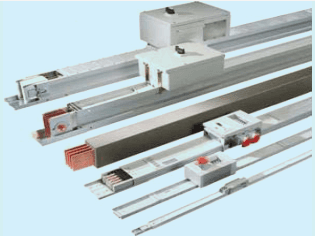
Fig. 1 Bus-Bar Trunking (BTS) and Tap-Off Boxes
5.3.2.2 BTS may be considered as an alternative with following attributes:
a) It is prefabricated in sections;
b) All accessories are factory made and precisely designed and is less prone to human error;
c) The installation including jointing, terminations, and tap-offs are convenient and do not require special skills and workmanship;
d) Additions/alteration are non-complex in nature;
e) Predefined electromagnetic induction values - lower electromagnetic interference;
f) Lesser voltage drops;
g) Better heat dissipation;
h) Good earth continuity;
j) Higher short-circuit withstand capacity;
k) Higher impulse voltage withstand capacity;
m) BTS may require reduced number of switchgears and hence, results in saving space and reduced sizing of panels;
n) Cable mess is eliminated. Also, it is halogen free and do not pose risk of toxic fumes generation in caseof fires and flame propagation; and
p) Ingress protection prevents possible damages due to rodents etc.
5.3.2.3 In high-rise buildings for vertical distribution and in large complexes, for horizontal distribution above mentioned attributes are desirable.
NOTE — Manufacturer’s specifications may also be referred.
5.3.2.4 BTS are of two types ‒ sandwich type or air insulated type. Generally, air insulated bus is manufactured for lower current ranges in comparison with sandwich bus. Air-insulated bus requires more space as compared to sandwich bus. It may cause chimney effect unless provision of fire barriers is provided. Considering the risks, use of air-Insulated BTS is not recommended in multistoreyed buildings above 15 m height, without provision of barriers.
PT system shall comply with IEC 61534 series of standards. Installation shall be carried out as per the manufacturer’s instructions.
5.3.3.1 PT system technology is a convenient option for conventional fixed power/data/telephone sockets. It is prefabricated and hence, can be installed easily and quickly. It allows addition, repositioning, removal of power and data/telephone sockets safely as and when required. This system provides great flexibility and can be used at locations where detailed interior layouts are not finalized.
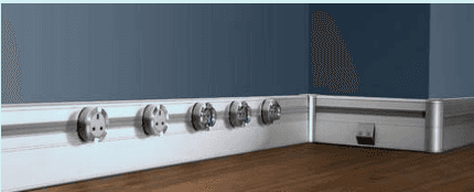
Fig. 5 Power Track System
SP 30 : 2023
5.3.3.2 PT system is used for rated voltage not exceeding 240 V for single phase and 415 V for three-phase with rated current not exceeding 63A. These systems can be used for distributing electricity in household, commercial and industrial installations. Installation of this system shall be done as per the manufacturer’s instructions.
5.3.3.3 It can be used on walls, skirting, and ceiling. Also, they can be of flush or semi-flush, surface mounted, suspended or spaced away from surface using fixing devices and shall comply with the norms specified in IEC 61534-21.
5.3.3.4 PT system may also be installed on floor/under floor complying with the requirements and tests specified in IEC 61534-22.
In reference with Table 1 of Part 1/Section 8 of this code, following external influences depending on location/ environment shall be taken into account so that protection against the expected external influences is ensured during selection and erection of wiring system:
a) Ambient temperature (AA);
b) External heat sources;
c) Humidity (AB);
d) Water (AD);
e) Presence of solid foreign bodies (AE);
f) Presence of corrosive/polluting substances (AF);
g) Mechanical stresses – impact (AG);
h) Mechanical stresses – Vibration (AH);
j) Mechanical stresses – other (AJ);
k) Flora, mould (AK);
m) Fauna (AL);
n) Solar radiation (AN);
p) Seismic effects (AP);
q) Wind (AR);
r) Nature of processed or stored materials (BE); and
s) Building design (CB).
For further detailed classification, refer Annex L from IS 732 : 2019.
Depending on geographical location, wiring system shall be suitable for the range limiting highest and lowest temperature in normal operation. In case of fault, limiting temperature which is maximum continuous operating temperature shall not exceeded (Refer Table 1 of Part 1/Section 8 of this code). Conventionally, AA4 (-5 to 400C), is regarded as normal limit.
Where wiring installation is likely to be exposed to external heat sources it shall be protected with heat shielding/ heat resisting insulated sleeving or segregating/placing sufficiently away from such heat source.
NOTE — Heat from external sources may be radiated or transferred through convection or conducted means. For example, from hot water system, appliances, manufacturing process, plant etc.
Under humid environment, condensation shall not cause any damage. Insulation and sheath (in case of sheathed cable) shall not allow penetration of moisture. Under this category, AB4 (RH 5 percent to 95 percent and AH 1 Low Severity) is treated as normal.
Wiring system shall comply relevant ingress protection class. And, if water accumulates, provision of draining shall be provided.
NOTE — In general, the sheaths and insulation of cables for fixed installations may be regarded, when intact, as proof against penetration by moisture. Special considerations apply to cables liable to frequent splashing, immersion or submersion.
| Sl No. | Type of Insulation | Temperature Limit °C¹⁾ |
| (1) | (2) | (3) |
| (i) | Thermoplastic (PVC) | 70 at conductor |
| (ii) | Thermosetting (XPLE/EPR rubber) | 90 at conductor²⁾ |
| (iii) | Mineral (thermoplastic PVC) covered or bare exposed to touch | 70 at sheath |
| (iv) | Mineral (bare exposed to touch but not in contact with combustible material) | 105 at sheath2),3) |
| ¹⁾ Current carrying capacities are based on temperatures mentioned above or where certified conductor or cable may have maximum operating temperature limits in accordance with the manufacturer's specifications. ²⁾ Where conductor operates exceeding 70°C, it shall be ascertained that the equipment connected to the conductor is suitable for the resulting temperature at the connection ³⁾ For mineral insulated cables higher operating temperature may be possible depending upon the temperature rating of cable, its terminations, environmental conditions and external influences.NOTES1 Table does not include all types of cables.2 This does not apply to bus-bar trunking system or power- track system or lighting track system for which current carrying capacity is provided by manufacturer.3 For temperature limit of other types of cable please refer cable specifications or manufacturer. | ||
Wiring system shall comply with relevant ingress protection class depending on its location. Where dust in significant quantities is present, additional measures may be taken so that heat dissipation is not affected, or cause creepage between conductors (for example, mining work, stone crushers etc.)
In presence of corrosive or polluting substance (for example, water, chemical zones, coastal areas etc.) all material and installation shall have additional provisions to resist such environment. Protective tapes, paint, grease, bimetallic accessories etc. as recommended by manufacturer shall be used.
Selection of wiring system shall take into consideration possible impact, penetration, compression etc. during installation, use or maintenance (for example, drilling a hole in wall where concealed wiring exists, digging where underground cable exists). Provisions such as be trunking ducting, conduit system may be used.
Wiring system supported by or fixed to structures shall sustain possible vibrations. Such situation may occur during casting of RCC work where conduits are fixed to steel and vibrators are used for proper settlement of concrete. Vibrations may be of medium severity (AH2) or high severity (AH3). Precautionary measure may include making conduit system rigid, using flexible wires etc., at the locations susceptible to such situations.
Sufficient care shall be taken to prevent mechanical stresses to affect reliability and safety of wiring installation (for example, unsupported heavy cable creates stress at terminals due to its own weight, pulling/threading of cables through conduit systems, bending of cables, underground/under floor cables, electro-dynamic forces resulting from short circuit currents, etc.)
Special protective measures such as regular cleaning shall be adopted at places where growth of vegetation and/ or fungus can cause a potential hazard.
At locations anticipated to constitute hazard (AL2) caused due to insects, birds, lizards, rodents etc. suitable measures shall be adopted by providing mechanical protection/suitable pest control which shall not cause adverse effect on installation.
SP 30 : 2023
Adequate shielding shall be provided where solar radiation (AN2) or UV radiation is expected. Special precaution shall be taken for equipment subjected to ionizing radiation.
Wiring system shall sustain seismic hazard identified for respective geographical location.
Please refer 5.2.5.13 of IS 732:2019.
Adequate fire prevention measures shall be taken for locations storing material having fire potential. for further information, refer 5.2.5.14 and 4.3.2 of IS 732 : 2019.
Where structural movement is anticipated wiring system shall permit relative movement (CB3)/(CB4) so that conductors and cables are not subjected to excessive mechanical stress such as expansion joints in the building structure, bridges, etc.
5.5.1 The current to be carried by any conductor for sustained periods during normal operation shall be such that the temperature limit depending on type of insulation is not exceeded as given under Table 2. Other than normal operation, consideration shall also be in regard with the ability to sustain effective operation of protection against electric shock, over-current, voltage drop (see 5.7), thermal effect and limiting temperature of conductor and terminals. All these considerations form basis of cross-section of conductor.
5.5.2.1 To assess current carrying capacity of cable depending on various situations given under Table A-3, these methods of installation have been classified under 10 groups under following references:
Insulated conductors in conduit in thermally insulated wall/in mouldings/architraves/window frames.
Multi-core cable in conduit in thermally insulated wall.
NOTE — Insulated wall consisting of outer weatherproof skin, thermal insulation and inner skin of wood or similar material having thermal conductance at least 10 W/m2. Conduit is fixed so as to be close to inner wall but not necessarily touching inner skin. Heat from cables is assumed to escape through the inner skin only. The conduit can be of metal or PVC.
Insulated conductors in conduit/trunking on wooden wall on/or concealed in masonry wall, suspended in trunking/in building void
Multi-core cable in conduit/trunking on wooden wall on/or concealed in masonry wall/flooring, suspended in trunking/building or ceiling void/duct in void/in masonry/open or closed cable channel
NOTE — Conduit is mounted on a wooden wall so that the gap between the conduit and the surface is less than 0.3 times the conduit diameter. The conduit can be of metal or plastic. Where the conduit is fixed to a masonry wall the current-carrying capacity of the cable or insulated conductors may be higher.
Single-core or multi-core cable on a wooden wall imperforated tray/on or directly in masonry wall/ ceiling.
NOTE — Cable mounted on a wooden wall so that the gap between the cable and the surface is less than 0.3 times the cable diameter. Where the cable is fixed to or embedded in a masonry wall the current-carrying capacity may be higher.
Single core cable/multi-core cable in conduits/ducts in the ground.
NOTE — Cables drawn into 100 mm diameter of plastic, earthenware or metallic ducts laid in direct contact with soil having a thermal resistivity of 2.5 K∙m/W and a depth of 0.75 m. For higher soil resistivity, apply correction factor as per Table B-16.
Multi-core cables designed to be buried directly in the ground with or without added mechanical protection (for example, half round RCC pipe etc.)
NOTE — Cables laid in direct contact with soil having thermal resistivity of 2.5 K∙m/W and a depth of 0.75 m. For higher soil resistivity, apply correction factor as per Table B-16.
h) Reference Method E
j) Reference Method F
k) Reference Method G
Reference method E, F, G is for single or multi-core cables in free air/spaced from surface/on perforated or wire-mesh tray/ladder/brackets/on insulators.
NOTE — A cable so supported that the total heat dissipation is not impeded. Heating due to solar radiation and other sources shall be taken into account. Care shall be taken that natural air convection is not impeded. In practice, a clearance between a cable and any adjacent surface of at least 0.3 times the cable external diameter for multi-core cables or one time the cable diameter for singlecore cables is sufficient to permit the use of current-carrying capacities appropriate to free air conditions.
This is similar to reference method C except that the current-carrying capacity for a cable on a ceiling is slightly reduced (see Table B-17 from Annex B) from the value for a wall or a floor because of the reduction in natural convection.
b) Cable Tray System
A perforated cable tray has a regular pattern of holes so as to facilitate the use of cable fixings. The current-carrying capacity for cables on perforated cable trays are derived from test work utilizing trays where the holes occupying 30 percent of the area of the base. If the holes occupy less than 30 percent of the area of the base, the cable tray is regarded as imperforated. This is similar to reference method C.
c) Cable Ladder System
This construction offers a minimum of impedance to the air flow around the cables, that is, supporting metal work under the cables occupies less than 10 percent of the plan area.
d) Cable Cleats, Cable Ties:
It is a device for fixing cables to cable tray or bundling cables together.
e) Cable Hangers:
Cable supports which hold the cable at intervals along its length and permit substantial free air flow around the cable.
f) Cables in a Ceiling:
This is similar to reference method A. It may be necessary to apply the correction factors due to higher ambient temperatures that may arise in the junction boxes, heat dissipating luminaries and similar items mounted in the ceiling. Correction factor as per Table B-14 of Annex B shall be applied.
5.5.3. Depending on reference method (see 5.5.2) and insulation (see Table 2), Table B -1 refers Table B -2 to Table B-13 which provide current carrying capacity for respective cross section and type of conductor (Cu/Al) can be taken for design consideration. Table B-14, Table B-15 and Table B-16 state the further correction Factors and Tables B-17 to Table B-21 state reduction factors to be applied. These tables are given under Annex B. Particulars are tabulated as below:
Table 3 Reference Tables for Assessing Current Carrying Capacity
(Clause 5.5.3)
| Table | Particulars | Use |
|---|---|---|
| B-1 | Installation reference methods for forming basis of tabulated current carrying capacities | Provides reference for obtaining current carrying capacity for particular cross section and conductor Cu/Al |
| B-2 | Current carrying capacities in amperes for PVC insulated, two loaded conductors copper (1.5 to 300 mm2)/aluminium (>16 to 300 mm2) conductor temperature 70°C with ambient temperature 30°C in air and 20°C in ground | Provides current carrying capacities under methods of installation A1, A2, B1, B2, C, D1, D2 |
To assess the required current carrying capacity, multiple factors shall be taken into account for calculating the current carrying capacity of particular cross section of conductor. Following steps shall be taken for calculation:
Step 1
Decide type of wiring – surface/flush to the surface/concealed/underground/in air
Check situation – walls (masonry/wooden,/insulated), flooring (masonry/raised), ceiling, ducts, shafts, voids, ground where wiring is to be installed.
Check for the reference method of installation (see 5.5.2.1) or other methods (see 5.5.2.2), for wiring decided (as per step 1) to fit in.
Select/decide type of insulation of cable to be used from Table 2. Thermoplastic (PVC)/Thermosetting (XLPE cross-linked polyethylene/EPR – ethylene propylene rubber)/mineral
1 Table 2 gives temperature withstand capacity depending on type of insulation. Wiring system components including cables and wiring accessories shall only be installed or handled at temperatures within the limits stated in the relevant product standard or as given by the manufacturer.
2 In absence of specific instructions from manufacturer, insulation having FR/FRLSH grade shall be treated under thermoplastic category of PVC to consider temperature withstand capacity.
3 In respect of FS cables manufacturer’s specifications shall be considered.
Check/decide number of cores.
Refer Table B-1 to refer current carrying capacities.
To apply ambient temperature factor for reference methods A1, A2, B1, B2, C, E, F, G, use Table B-15 and for reference methods D1 and D2, use Table B-15.
For reference method D1 and D2, apply correction factor if soil resistivity is other than 2.5 K-m/W (see Table B-16).
Apply reduction factor depending on the number of circuits from Table B-17 for above ground, Table B-18 for below ground and for duct in ground Table B-19.
Apply group reduction factor from applicable table (Table B-20/Table B-21) for reference method of installation E and F as mentioned in Table B-1.
NOTE — If the same circuit (continuous conductor between terminations) passes through different locations requiring different methods of installation (for example, part of wiring is in void above false ceiling and part wiring embedded in walls, the lowest current carrying capacity shall be considered.)
Alternatively, to assess current carrying capacity of cable, a simplified version is given in Table C-1, Table C-2 and Table C-3 of Annex C.
Where the neutral conductor carries current without a corresponding reduction in load of the line conductors, the current flowing in the neutral conductor shall be taken into account while ascertaining the current-carrying capacity of the circuit. The magnitude of neutral current due to third harmonic and further, triplen harmonics causes significant effect on current carrying capacity of the cables in the circuit.
SP 30 : 2023
The equipment likely to cause harmonic current are fluorescent luminaries, LED luminaries, computers, VVVF drives and inverter technology based electrical gadgets.
5.6.3.1 Where the neutral current is likely to be higher than the line current, then, cable size shall be selected on the basis of neutral current.
5.6.3.2 Where the cable size selection is based on a neutral current which is not significantly higher than the line current, it is necessary to reduce the tabulated current-carrying capacity for three loaded conductors.
5.6.3.3 If the neutral current is more than 135 percent of the line current and the cable size is selected on the basis of the neutral current, then the three-line conductors will not be fully loaded. The reduction in heat generated by the line conductors offsets the heat generated by the neutral conductor to the extent that it is not necessary to apply any reduction factor to the current-carrying capacity for three loaded conductors.
5.6.4.1 In balanced three-phase circuits, harmonic content of neutral currents due to the line currents is not cancelled. Under the circumstances, reduction factors shall be applied. If only two of the three phases are loaded, the neutral conductor carries the harmonic currents in addition to the unbalanced load current. Such a situation can lead to overloading of the neutral conductor.
5.6.4.2 If more than 15 percent of higher harmonics (for example, 9th, 15th, etc.) are expected, then, lower reduction factors are applicable. In case of more than 50% unbalance between phases, lower reduction factors may be applicable.
5.6.4.3 The tabulated reduction factors when applied to the current-carrying capacity of a cable with three loaded conductors give the current-carrying capacity of a cable with four loaded conductors where the current in the fourth conductor is due to harmonics. The reduction factors also takes into account the heating effect of the harmonic current in the line conductors.
| Sl No. | Third Harmonic Content of Line Current % | Reduction Factor | |
| Size Selection is Based on Line Current | Size Selection is Based on Neutral Current | ||
| (1) | (2) | (3) | (4) |
| 1 | 0-15 | 1.0 | -- |
| 2 | 15-33 | 0.86 | -- |
| 3 | 33-45 | -- | 0.86 |
| 4 | 45 | -- | 1.0 |
1 The triplen harmonic content of the line current is the ratio of the third harmonic and the fundamental (first harmonic), expressed in percent.
2 The reduction factors only apply to cables where the neutral conductor is within a four-core or five-core cable and is of the same material and cross-sectional area as that of line conductors. These reduction factors have been calculated based on triplen harmonic currents.
Consider a three-phase circuit with a design load of 39 A to be installed using four-core PVC insulated cable clipped to a wall, installation method C.
From Table B-4, a 6 mm2 cable with copper conductors has a current-carrying capacity of 41A and hence is suitable if harmonics are not present in the circuit.
Example 1 If 20 percent third harmonic is present, then a reduction factor of 0.86 is applied and the design load becomes:
For this load a 10 mm2 cable is necessary.
Example 2 If 40 percent third harmonic is present; the cable size selection is based on the neutral current which is:
3 9 * 0. 4 * 3 = 4 6. 8 A
and a reduction factor of 0.86 is applied, leading to a design load of:
The voltage drop between origin of an installation and any load point shall have limitations as given in the Table 5.
| Table 5 Voltage Drop Limitation(Clause 5.7) | |||
| Sl No.(1) | Type of Installation(2) | Lighting(3) | Other(4) |
| i) | A – low voltage installation supplied directly from public low voltage distribution system | 3 percent | 5 percent |
| ii) | B – low voltage installation supplied from private LV supplya | 6 percent | 8 percent |
| a It is recommended that voltage drop within final circuits does not exceed those indicated in installation type A.When the main wiring system of installation is longer than 100 m these voltage drops may be increased by 0.005 percent per meter exceeding 100 m, without this supplement being greater than 0.5 percent.Voltage drop is determined on the basis of demand by the current using equipment, applying diversity factor where applicable or from the values of the design current of circuits. | |||
| NOTES | |||
| 1 Greater voltage drop may be accepted:a) for motor during starting period; andb) for other equipment having high inrush current. | |||
| 2 Following temporary conditions are excluded:a) voltage transients, andb) voltage variation due to abnormal operation. | |||
| 3 For extra low voltage circuits, it is not necessary to fulfill the voltage drop limits mentioned in this table for uses other than lighting (for example, bell, control, door opening, etc.) provided that it is ensured that the equipment is operating correctly. | |||
While selecting conductor for size less than or equal to 16 mm2, copper conductor of Class 1 or Class 2 is recommended. Over the period of time, loosening of contacts and oxide formation is prominent in Aluminum conductors which may lead to increased generation of heat and sparking.
SP 30 : 2023
NOTE — Loose contacts are major cause heat generation leading to sparking and fire. Under routine maintenance, contacts of lighting circuits in switchboards may not be checked. Under these circumstances to mitigate the possibilities of fire hazard due to loose contacts, copper conductor is recommended.
Cross-sectional areas of conductor shall be selected considering following factors:
a) requirement of maximum current depending on designed/estimated load (including anticipated future requirement) under normal conditions;
b) fault level withstand capacity;
c) allowable voltage-drop1) (see 5.7);
d) harmonic disturbances (see 5.6); and
(e) current carrying capacity2) of the conductor under the respective situation and method of installation (see 5.5).
5.8.3 Without prejudice to the above recommendations, the nominal cross section area of phase conductors in a.c. circuits and live conductor in d.c. circuit shall not be less than values specified in Table 6 due to mechanical reasons.
| Table 6 Minimum Nominal Cross-Sectional Area of Conductors(Clause 5.8.3) | |||
| Sl No.(1) | Type of Wiring(2) | Use of Circuit(3) | Conductor and Cross Section(4) |
| i) | Fixed installation cables and insulated conductors | Lighting circuits¹⁾ power outlet²⁾ 6A | 1.5 mm²Cu |
| ii) | Power circuits/, | 2.5 mm²Cu | |
| iii) | Power outlet³⁾ 6A | ||
| Power outlet⁴⁾ 16A | |||
| Appliance⁵⁾ < 2 kW | |||
| iv) | Appliance⁶⁾ < 3 kW | 4.0 mm²Cu | |
| v) | Appliance⁷⁾ < 6 kW | 6.0 mm²Cu | |
| vi) | Signaling and controlling circuits | ⁸⁾0.5 mm²Cu | |
| vii) | Flexible connections with insulated conductors and cables | For specific appliance | Cu (Class 5) |
| viii) | For any other application | ⁸⁾0.5 mm²Cu | |
| xi) | Extra low voltage circuits | 0.5 mm² | |
| ¹⁾ Maximum looping - 2 boards, subject to load < 1 kW/24 points ²⁾ Maximum 4 Nos., subject to total load < 1 kW ³⁾ Maximum 8 Nos., subject to total load < 2 kW ⁴⁾ Maximum 2 Nos., subject to total load < 2 kW ⁵⁾ 1 No, subject to total load < 2 kW/AC < 1TR ⁶⁾ 1 No, subject to total load < 3 kW/AC < 2TR/3TR (3-PH) ⁷⁾ 1 No, subject to total load < 6 kW/AC < 3TR (1-PH) 8) In multi-core flexible cables containing 7 or more cores and in signaling control circuits intended for electronic equipment, a minimum nominal cross-sectional area of ( 0.1 mm2 is permitted. | |||
5.8.4.1 In single phase circuits with two conductors and in three phase circuit with line conductor up to 16 mm2 Cu or 25 mm2 Al or where harmonic distortion is likely and THD is between 15 and 33 percent, cross sectional area of neutral conductor shall be at least equal to the area of line conductor.
Voltage drop directly correlates with the losses. Energy Conservation Building Code (ECBC) recommends limit for the total power losses, which ranges from 1 percent to 3 percent depending on Super ECBC, ECBC+, ECBC.
It shall be noted that for the same cross section of conductor, variation in current carrying capacity is quite large. Typically, it will be seen that under Table C-1, current carrying capacity of 1.5 mm2 copper conductor varies from 13A to 26A, depending on situation and method of installation.
5.8.4.2 If THD exceeds 33 percent, cross-sectional area of neutral conductor shall be increased (see 5.6).
5.8.4.3 For poly phase circuits where cross sectional area of line conductor is greater than 16 mm2 copper or 25 mm2 aluminum, cross-sectional area of neutral conductor may be lower (but not less than 50 percent) than cross sectional area of the line conductors if following conditions are fulfilled simultaneously:
a) the load carried by the circuit in normal service is balanced between the phases;
b) third harmonics and the odd multiple of third harmonics current do not exceed 15 percent of the line conductor current;
c) the neutral conductor is protected against over currents; and
d) cross sectional area in not less than 16 mm2 Cu or 25 mm2 Al.
NOTE — For polyphase circuits, adequate provision shall be provided to operate switching device simultaneously on all phases and neutral to prevent single phasing.
Cross sectional area of protective conductor shall not be less than the appropriate value shown in Table 7.
Table 7 Cross Section Area of Protective Conductor
(Clause 5.8.5)
| Sl No.(1) | Cross section Area of Phase Conductor S mm² (Cu)(2) | Minimum Cross Section Area of Protective Conductor mm² (3) |
| i) | S<16 | S |
| ii) | 1616 | 16 |
| iii) | S>35 | refer 17.2.2.1 of IS 3043 |
| NOTES | ||
| 1 Applicable for same metal. If different metal is used, it shall have same ampacity. If exact size is not available, nearest next size is chosen. | ||
| 2 The values shown above are generally applicable. For precise size, 12.2.2.1 of IS 3043 or 5.4.3.1.3 of IS 732 may be referred. It may be economical leading to small cross section compared to phase conductor. For IT and TT system of earthing, compatibility may be verified in consideration with earth fault loop impedance. | ||
5.9.1 Conduits shall comply with IS 9537 series of standards and conduit systems shall comply with IS 16205 series of standards. For underground conduits, IS 14930 (Part 2) shall be referred. (see 5.9.6)
The basic function of conduits is to provide mechanical, environmental and fire protection to cabling system. Depending on the characteristics, conduits are classified and coded as in Table 8.
NOTE — For conduits to be buried underground, also refer 5.9.5.
a) material – metal/insulating/composite;
b) connecting – threadable/non-threadable
c) mechanical properties (stresses) – very light/light (LMS)/medium (MMS)/heavy (HMS)/very heavy;
d) bending – rigid/flexible/pliable/self-recovering;
e) flame propagation – propagating/non-propagating;
f) electrical – insulating/non-insulating;
g) external influences – temperature/ingress of water/corrosion; and
NATIONAL ELECTRICAL CODE OF INDIA
h) solar radiation – unprotected/protected.
| SI No. | Digit | Code | Class |
| (1) | (2) | (3) | (4) |
| (i) | 1st | 1 | Very light |
| Resistance to compression | 2 | Light | |
| 3 | Medium | ||
| 4 | Heavy | ||
| 5 | Very heavy | ||
| (ii) | 2nd | 1 | Very light |
| Resistance to impact | 2 | Light | |
| 3 | Medium | ||
| 4 | Heavy | ||
| 5 | Very heavy | ||
| (iii) | 3rd | 1 | +5°C |
| Lower temperature range | 2 | -5°C | |
| 3 | -15°C | ||
| 4 | -25°C | ||
| 5 | -45°C | ||
| (iv) | 4rd | 1 | +60°C |
| Upper temperature range | 2 | +90°C | |
| 3 | +105°C | ||
| 4 | +120°C | ||
| 5 | +150°C | ||
| 6 | +250°C | ||
| 7 | +400°C | ||
| (v) | 5th | 1 | Rigid |
| Resistance to bending | 2 | Pliable | |
| 3 | Pliable/self-recovering | ||
| 4 | Flexible | ||
| (vi) | 6th | 0 | None |
| Electrical characteristic | 1 | Electrically continuous | |
| 2 | Electrically insulating | ||
| 3 | Electrically continuous and insulating | ||
| (vii) | 7th | 3 | >2.5 mm |
| Ingress to solid objects | 4 | >1.0 mm | |
| 5 | Dust protected | ||
| 6 | Dust tight | ||
| (viii) | 8th Resistance to ingress of water | 0 | None |
| 1 | Vertical drops | ||
| 2 | Drops on conduit @15° | ||
| 3 | Spray | ||
| 4 | Splash | ||
| 5 | Jets | ||
| 6 | Powerful jets | ||
| 7 | Temporary immersion | ||
| (ix) | 9th | 1 | Low - In and out |
| Resistance against corrosion | 2 | Medium - In and out | |
| 3 | Medium-In, High-out | ||
| 4 | High - In and out |
| Table 8 (Concluded) | |||
|---|---|---|---|
| Sl No. | Digit | Code | Class |
| (1) | (2) | (3) | (4) |
| (x) | 10<sup>th</sup> Tensile strength | 012345 | None Very light Light Medium Heavy Very heavy |
| (xi) | 11<sup>th</sup> Resistance to flame propagation | 12 | Non flame propagating Flame propagating |
| (xii) | 12<sup>th</sup> Suspended load capacity | 012345 | None Very light Light Medium Heavy Very heavy |
5.9.3.1 Selection of conduit shall be on the basis of suitable characteristics required for protection and management of insulated conductors/cables and survival under respective site conditions, external influences and situation. However, broadly conduits can be divided in to metallic and non-metallic.
Metal conduits provide good mechanical protection. Usually, these conduits are available in Electric Resistance Welded (ERW), Electric Metal Tubing (EMT) and Galvanized. For ERW conduits are welded longitudinally and EMT is seamless. Metal conduits provide increased fire safety as it is does not catch fire and produce toxic smoke. However, metal conduits are susceptible to corrosion. Under moist and humid atmosphere where condensation is likely and also, under chemical zones, decision about its use shall be taken judiciously. Hot dipped Galvanised Conduits are more favourable under corrosive environment.
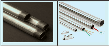
Fig. 6 Hot Dipped Galvanized Conduit and Emt
1 For more information, refer Annex D (see Annex W of IS 732).
2 In case of requirement of conduit to provide mechanical protection to underground cable, it shall conform to relevant national/ international standards.
PVC conduits provide adequate resistance, protection against mechanical impacts and provide additional insulation against corrosion. PVC conduits are cheaper and easier to install. Depending on situation, selection of conduits may be made.
NOTES
1 If quality of two or more options are available, criteria for selection shall include time required for installation, quality of workmanship, labour for required skill and estimated cost and material component. For example, installation of metal conduits requires cutting, bending, threading, requiring specialized skill, workmanship, labour and time.
SP 30 : 2023
2 With advancement in technology, PVC conduits are increasingly replacing metal conduits. However, use of metal conduits is predominant where risk due to mechanical damages is high such as in industrial installation.
Electrical conduit system shall be non-flame propagating. Depending on fire hazard, risks at public gathering places and other sensitive installations, use of PVC conduits with fire retardant/fire retardant with low smoke, halogen, and lead dissipating properties is recommended.
Un-plasticized PVC conduits provide high resistance to corrosion, UV effect and fire. These conduits have smooth surface which helps in drawing of wires. However, the flexibility is relatively less.
Installation of conduit systems can be primarily categorized into surface type and concealed type. The choice shall depend on level of planning, aesthetics, cost, maintenance and additions/alteration of installations.
Surface wiring facilitates ease of change. Concealed type wiring suites aesthetic requirements but requires pre-planning and comparatively, costs higher. Clearing fault and carrying out changes in concealed wiring is difficult as compared to surface type wiring. Whether surface type or concealed installation, safety shall be a priority.
NOTE — Installation of conduit systems shall be carried out as per the manufacturer’s instructions. After assembling, the installation shall be safe and shall have resistance to external influences with minimum requirement of IP 67.
a) Layouts shall be precisely planned and marked in coordination with other utility services so as to not endanger safety. for example, at sufficient distance from gas pipeline.
b) Depending on layout, sequence of installation activity shall also be in coordination and shall not conflict works related to other utility services.
c) Conduits for wiring systems which are rigidly fixed and concealed in the walls shall run horizontally, vertically or parallel to the room edges. Wiring systems in ceilings or in floors may follow the shortest practical route. Sharp bends shall be avoided. In straight length between two pull-on/junction boxes maximum bends shall not be more than two.
d) When there are several conduits running in parallel, they must be arranged to avoid crossing at the point where they take different directions.
e) Layouts shall take in to consideration the bending radii of cables.
Fixing of conduit on surface may be done with saddle/saddle with spacer/clips. For spacing between supports (refer Table D-5 of Annex D):
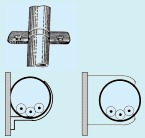

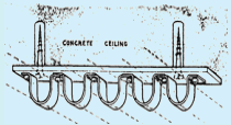
Fig. 8 Methods of Fixing Conduit with Clip, Saddle/S, Saddle and Spacer
Screws, clamps/attaching component or joints to conduits shall not cause damage to the insulation of wire. The screws shall be fixed with plugs and shall have adequate length depending on the consistency of the base on which conduits are fixed. On stone walls, fixing may need additional wooden wedges/gutty to hold the screw firmly. In concealed type of wiring in walls, conduits may be fixed with ‘U’ nails.
Conduit system to be buried in ground shall conform with the requirements specified in IS 16205 (Part 24). Changes with respect to IS 14930 (Part 1) for the conduits to be buried under ground are as under:
a) Multiwall conduit category included for underground use;
b) For Resistance to Impact, there are only two categories ‒ normal duty (N) and light duty (L);
c) Under external influences, resistance to chemical attack is additional; and
d) Minimum inside diameter is nominal outside diameter divided by 1.33.
5.10.1 Trunking/ducting system shall conform to IS 14927. Trunking is meant to provide mechanical, environmental and fire protection at different levels for insulated conductors/cables. These systems are used for surface type wiring.
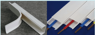
Fig. 13 PVC Trunking (Casing Capping)
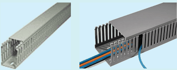
Fig. 14 Slotted Trunking/Ducting
Depending on the characteristics Conduits are classified and coded as below:
a) material – metal/insulating/composite;
b) mechanical properties – very light/light/medium/heavy/very heavy;
c) temperature – states operative temperature range;
d) flame propagation – propagating/non-propagating;
e) electrical – without electrical continuity, with electrical continuity, insulating;
f) external influences – temperature/ingress of solid/water/corrosion;
g) solar radiation – unprotected/low, medium, high protection; and
83
h) cover retention – cover removable with tools/without tools.
Trunking and ducting system shall be flame retardant. Depending on fire hazard, risk at public gathering places and other sensitive installations, use of trunking/ducting having fire retardant/fire retardant with low smoke, halogen, and lead emmission properties is recommended.
| Sl No. | Size (outer) mm | Wall Thickness mm | Approximate Internal Cross Section mm2 |
| (1) | (2) | (3) | (4) |
| 1 | 12 × 12 | 1.2 | 119.5 |
| 2 | 16 × 12 | 1.2 | 153.0 |
| 3 | 16 × 16 | 1.2 | 196.0 |
| 4 | 25 × 12 | 1.2 | 239.1 |
| 5 | 25 × 16 | 1.2 | 307.4 |
| 6 | 25 × 25 | 1.2 | 510.8 |
| 7 | 38 × 16 | 1.3 | 474.4 |
| 8 | 38 × 25 | 1.3 | 793.0 |
| 9 | 50 × 16 | 1.5 | 611.0 |
| 10 | 50 × 50 | 1.5 | 2209 |
| 11 | 75 × 75 | 1.8 | 5098 |
| 12 | 100 × 50 | 1.8 | 4473 |
| 13 | 100 × 40 | 2.5 | 3333 |
| 14 | 200 × 30 | 2.5 | 5000 |
| 15 | 225 × 25 | 1.6 | 4687 |
| 16 | 225 × 38 | 1.6 | 7125 |
| 17 | 250 × 25 | 1.6 | 5103 |
| 18 | 250 × 38 | 1.6 | 7916 |
| 19 | 300 × 25 | 1.6 | 6250 |
| 20 | 300 × 30 | 2.5 | 7500 |
| 21 | 300 × 38 | 1.6 | 9500 |
NOTE — The sizes other than those specified in above table are also acceptable within width and height ranging from 12 to 300 mm provided that above width or height of 50 mm, wall thickness shall be at least 1.8 mm for trunking/ducting of insulating material and 1.6 mm for trunking/ducting of metal.
5.10.4.1 Construction shall be such that any surface, edge, screws, stud or other securing device does not damage to conductor or cables.
Trunking/ducting system may be fixed with suitable contact adhesive or mounting device. Fixing screws and small spring clips of insulating trunking fitting need not be of insulating material provided that they do not come into contact with the conductors/In case of any such possibility, fixing may be done with screws, using PVC plugs and shall be so designed to withstand the mechanical stresses occurring during installing and normal use.
If there is provision of segregation of circuits, the same shall be adequately secured.
5.10.4.4 Accessible metal parts of system components which are liable to become alive in event of failure of insulation, shall have provision to connect with earth.
Cable tray/ladder system is an assembly of units or sections along with associated fittings forming a structural system used to securely fasten or support cables and may also include Raceways. It is one of the efficient cable
management tools where routing of large quantum of cables are to be handled. This system can be used both for power and LV systems such as communication, data, control and signaling. It helps in ruling out possibility of disorganized mass of cables which may become difficult to trace at times. This system carries cables mostly in open state, hence, is advantageous for thermal management. In high-rise buildings, it can be one of the most suitable options suited for vertical distribution through shafts/ducts.
NOTE — Since cable ladder/Tray system is not fully enclosed, it does not offer complete mechanical and environmental protection. Therefore, this system is suitable for sheathed and armoured cables. Single insulated cables shall not be installed on system.
It shall conform to IS/IEC 61537 series of standards.
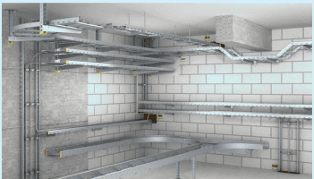
Fig. 15 Cable Ladder, Tray System
The ladder/cable tray has two side rails connected by cross members or rungs. The rungs provide convenient anchors for tying down the cables. A trough cable tray is a prefabricated structure consisting of a ventilated bottom with side rails. The ventilated trough cable tray supports cables better than the ladder type.
NOTE — Cable tray and ladder system is designed for use as support for cable. It is not an enclosure for providing mechanical protection. It is not intended to be used as support for a person working. Trying so may damage the system and cause injury to person.
These are available in wide variety of sizes, styles and material ‒ metal/non-metal (for example, hot-dip galvanized, zinc electroplated, epoxy powder coated, fiber optic, GRP, FRP). Selection can be made on the basis of mechanical properties, effects of external influences. Fiber-optic cable installations are installed with solid-bottom cable trays as the drooping of fiber-optic cables may degrade system performance. Also, selection of solid-bottom trays reduces sensitivity to electromagnetic/radio-frequency interference and/or circuit sensitivity.
NOTE — Corrosion in metallic cable ladder/Tray system may occur due to climatic conditions, pollution or chemical environment. It is very difficult to repair such damages. Hence, it is most important that appropriate material is selected.
Construction of cable ladders/trays shall be done considering full load conditions. Distance between supports/ span may be decided depending on load pattern. Proper structural analysis shall be made considering horizontal beam structure, vertical column supports and brackets fixed on walls/vertical surfaces as eccentric load. Design may be approved by Structural Engineer. For supports, safe working load data may be called from the manufacturer.
85
NOTE — IS/IEC 61537 states that manufacturer shall declare SWL (safe working load) details of the product.
Allowable deflection of cable ladder/tray along the length and deflection of supports shall be restricted within limit as mentioned in IS/IEC 61537.
There shall be correlation between bending radii of cable and radius of cable ladder/tray fittings and shall not be less than minimum bending radius of largest size of cable.
Provision shall be made for the cable and the cable ladder/tray system to expand and contract by providing expansion joints and loops of cable at these points.
Metallic/electrically conductive cable ladder/tray system shall retain adequate electrical continuity to ensure equipotential bonding and connection to earth.
Cable ladder/tray system do not support electromagnetic influences. However installation of current carrying cable may cause electromagnetic effects. This may cause disturbance in data networking cables. Necessary precautions may be taken as recommended in EN 50174-2.
Cables shall be fastened to ladder/tray with correct size cable ties/cleats or suitable fixture so as to sustain electro mechanical effects.
See 5.16 and 5.17
This is enclosed system of metallic/non-metallic material to provide protection for cables against external influences. Depending on situation, selection of system ‒ metallic or non- metallic and installation method – concealed type or surface type shall be made. Typical methods of installation can be seen under Table A-3 of Annex A.
While installing, following shall be checked:
a) where the wiring system is designed to be withdrawable, there shall be adequate means of access for drawing cable in or out;
b) if wiring system is designed to be buried in the structure, a conduit or cable ducting system for each circuit shall be completely erected before cable is drawn in;
c) radius of every bend in a wiring system shall be such that conductors and cables shall incur damage;
d) where a conductor or a cable is not continuously supported and is supported by suitable means at appropriate intervals, it shall be supported such that the conductor or cable does not suffer damage by its own weight;
e) cables or conductor used as fixed wiring shall be supported in such a way that they are not exposed to undue mechanical strain and there is no appreciable mechanical strain on the terminations of the conductors, taking into account the mechanical strain imposed by the weight of the cable or conductor on itself;
f) the conduits/trays, ladders, ducts, channels, raceways from where cables are to be pulled are cleared of burrs and sharp edges and shall be covered properly;
g) flexible wiring system shall be installed so that excessive tensile and torsion stresses to the conductors and connections are avoided; and
h) to facilitate pulling of heavy cables, provision of cable pulling equipment/tools shall be made.
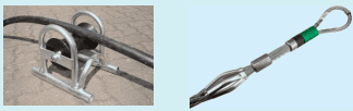
Fig. 16 Cable Pulling Tools
j) data cables, OFCs and other LV system cables having similar mechanical properties shall be handled and installed with special care. Selection and fixing of Cable ties shall be such that it does not damage the cable (for example, thin ties or very tightly fastened tie may pierce through the shield of cable).
k) continuity of protective conductor shall not depend on its intermediate connections with enclosures/ system of wiring enclosures, equipment or armouring.
During installation of wires/cables in any type of system/method, utmost care shall be taken to prevent damages to insulation. Bush shall be provided on open end of conduit at the time of drawing of wires. Twisting and bending is within permissible limits provided there is no risk at the time of installation and possibilities in future of External Influences which may affect insulation properties.
Number of wires/cables shall be restricted within the allowable fill factor/space factor specified for the respective system.
Care shall be taken to install and maintain design conditions related to spacing on based current carrying capacity of cables.
For identification of cables and conductors, IS 11353 gives guidance on uniform system of marking and identification of conductors and apparatus terminals (see Table E-1 under Annex E).
5.13.4.1 Every single core non-flexible cable and every core of twin or multicore non-flexible cable used as fixed wiring shall be identifiable throughout its length.
5.13.4.2 In case of Mineral insulated (MI) cables and bare conductors, colour sleeves may be used.
5.13.4.3 Colour coding of fixed wiring cables applies to all wiring up to the final distribution board and also, for circuit wiring, except red colored wire may be used for any phase.
5.13.4.4 For lighting, red wire shall be used from the switch to the lighting point.
87
5.13.4.5 For flexible cables and cords the distinctive colours are not same as those for fixed wiring. The colours for core identification are given in Table E-2 under Annex E.
Single-core cables armoured with steel wire or tape shall not be used for a.c. circuits. Conductors of a.c. circuits installed in ferromagnetic enclosure shall be arranged so that the conductors of all phases and the neutral conductor (if any) and the appropriate protective conductor of each circuit are contained in the same enclosure. Where such conductors enter ferrous enclosure, they shall be arranged so that the conductors are not individually surrounded by a ferrous material, or provision shall be made to prevent eddy (induced) currents (also see 5.11.7).
Under fault conditions, excessive current flowing through cable can last fraction of seconds to few seconds. Such currents create high magnetic field which can interact to produce large mechanical forces, causing displacement
and may lead to damaging of cable. Under such circumstances, proper type of fixtures help in transfer of these forces to the base. Such fixture shall also not cause damage to the cable.
It shall be ensured that the size of conductor and termination match properly. For all connections between conductors and connections between a conductor and terminal of electrical accessory, equipment shall provide:
a) durable electrical continuity by making connections sufficiently tight so that no charring or hot spot could be created;
b) all strands are properly inserted in terminal, where necessary use of appropriate type of lugs and metal (copper/aluminium/bimetal) is made;
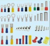
Fig. 17 Cable Lugs
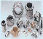
Fig. 18 Cable Glands
c) adequate mechanical strength so that weight of cable does not put strain on terminals. Where necessary, clamps shall be provided and appropriate type of glands shall be used;
d) temperature attained by terminal shall be within permissible range so that the effectiveness of the insulation of the conductors connected to them is not impaired; and
e) connections and terminations are done in suitable enclosures providing adequate mechanical protection and protection against external influences.
Selection of wires play an important role to address fire hazard risk. The degree of hazard depends upon the type of premises, its usage, occupancy etc. In order to prevent flame propagation during fire accident, wires/cables shall be of class FR/FRLSH/HFFR. Design of electrical installation shall recommend appropriate type and class of wire considering the following characteristics:
a) non propagation of flame – self-extinguishing;
b) low generation of smoke as it impairs visibility during fire; and
c) low or zero halogen as it causes toxic fumes/smoke which affects respiration system leading to suffocation and endangers life. Also, formation of acids leads to adverse effects on metal structures including steel embedded in concrete.
In addition to properties like low emission of smoke and corrosive gasses, FS cables are designed to withstand high temperatures. Use of FS cables shall, therefore, be made where integrity of electric supply is important especially to save human life and where electric supply is required for evacuation operation during the fire instances. These cables are designed to withstand temperatures from 6500C to 9500C and for period upto 180 min along with additional protection against mechanical shock and water splash. Categorized for Fire Survival is given in Table 10A.
Table-10A Fire Survival Categories
89
(Clause 5.14.2)
NOTE — For more details, refer 3.5 of IS 17505 (Part 1) : 2020.
| S. No.(1) | Parameter(2) | Functionality(3) | Symbol(4) |
| a) | Resistance to fire alone | 950°C for 180 min | Symbol F |
| b) | Resistance to fire and water | 650°C for 15 min followed by 5 bursts for water | Symbol W |
| c) | Resistance to fire and mechanical shock | 950°C for 15 min along with 3 mechanical impacts | Symbol S |
| Resistance to fire, water and shock | Category F3/F30/F60/F120 as below | Symbol FWS | |
| Category F 3 | Resistance to fire, resistance to fire with water, resistance to fire with mechanical shock, assessed separately when tested in accordance to E-7.3, E-7.4 and E-7.5 from Annex E of IS 17505 (Part 1) respectively. | ||
| Category F 30 | Resistance to fire with direct mechanical impact and water jet assessed in combination, when tested in accordance to Annex E for 30 min | ||
| Category F 60 | Resistance to fire with direct mechanical impact and water jet assessed in combination, when tested in accordance to Annex E for 60 min | ||
| Category F 120 | Resistance to fire with direct mechanical impact and water jet assessed in combination, when tested in accordance to Annex E for 120 min | ||
Table-10B Application of FS cable
(Clause 5.14.2)
NOTE ‒ For more details, refer Annex A of IS 17505(Part 1) : 2020.
| Sl No. | System Description | Cable Fire Rating Required (°C) | Time for which System should Withstand (Minutes) |
|---|---|---|---|
| (1) | (2) | (3) | (4) |
| i) | Fire pumps | FS (950/FWS) | 180 |
| ii) | Pressurization | FS (950/FWS) | 180 |
| iii) | Smoke venting including its ancillary systems, such as dampers and actuators | 950 | 60 |
| iv) | Fire-fighting shaft (staircase, lift, lift lobby) | FS (950/FWS) | 180 |
| v) | Fireman's lifts (including all lifts) | FS (950/FWS) | 180 |
| vi) | Exit signage lighting | 950 | 120 |
| vii) | Emergency lighting | 950 | 120 |
| viii) | Fire alarm system a) Conventional (zone-based system) b) Intelligent addressable system | 650650 | 6060 |
| ix) | Public address (PA)system (related to emergency voice evacuation and annunciation) | 650 | 60 |
| x) | Magnetic door hold-open devices | 650 | 60 |
| xi) | Lighting in fire command center and security room | FS (950/FWS) | 180 |
NOTE — Above recommendations shall not be taken as limited to and may also include installations of high importance involving security of occupants and assets. Such wires are intended to withstand high temperature for the required time period and retain integrity of supply to serve emergencies/critical services.
Where a wiring system such as conduit, cable ducting, cable trunking, bus-bar trunking etc. penetrates through elements of building construction such as floors, walls, roofs, ceilings, partitions or cavity barriers, the voids/ openings left after installation of the wiring system shall be sealed according to the degree of fire resistance
required for the element concerned. A part of a wiring system complying with the requirements of the relevant Indian Standard where testing for resistance to the propagation of flame is not mentioned such system shall be completely enclosed in non-combustible building material having the ignitability characteristic ‘P’.
Cables, conduits or ducts that are buried in the ground shall be laid with minimum depth of 750 mm or 1 000 mm for road crossing as per IS 1255 to assure protection against mechanical damage/impact.
NOTES
1 Depth shall be measured between finished ground level/surface and top edge of circumference of cable laid underground.
2 The depth mentioned is for LT and control cables
Cable shall be laid on bedding of minimum 75 mm riddled soil or sand at bottom of trench and covered with additional riddled soil or sand of 75 mm and further, shall be covered with bricks/tiles/half round RCC pipes to provide mechanical protection. Cables across the roads/railway tracks shall be laid through ducts/conduits of sufficient mechanical strength.
NOTE — Based on environmental aspects, scarcity of sand and local restriction on use of sand, riddled soil shall be used.
Buried cables shall be marked by cable covers or a suitable marking tape along with an indicator above ground showing route and voltage level so that buried conduits/ducts are identifiable during excavation.
5.15.4 Cable supports and enclosures intended to provide mechanical protection shall not have sharp edges liable to damage the cable or insulation of conductor. Such enclosure shall have minimum 1.5 times internal diameter with respect to diameter of cable and shall be capable to sustain load exerted by external situation of the vehicular traffic when laid across the road.
Clearances between cables (for example, power, telecommunication, data/IT related, internet etc.) shall be as mentioned in Table 11 or as per the respective service or standard, whichever is higher (see 5.16, 5.17, 5.18).
Table 11 Clearances for Underground Cables
(Clause 5.15.5)
| Sl No.(1) | Category of Cable/Service(2) | Clearance(3) |
| i) | Power cable to power cable | Not specific but shall suite de-rating factor |
| ii) | Power cable to control cable | 200 mm |
| iii) | Power cable to communication cable | 300 mm |
| iv) | Power cable to gas/water main | 300 mm |
| NOTE — Inductive influence of power cable on sensitive control cable shall be checked | ||
An extra-low voltage (Band I) SELV/PELV and/or a low voltage (Band II) circuit shall not be contained within the same wiring system of nominal voltage exceeding that of low voltage. Unless every cable is insulated for the highest voltage present, one of the following methods shall be adopted:
a) each conductor in a multicore cable is insulated for the highest voltage present in the cable, or is enclosed within an earthed metallic screen of current-carrying capacity equivalent to that of the largest conductor enclosed within the screen, or
b) the cables are insulated for the respective system voltages and installed in a separate compartment of a cable ducting or cable trunking system or have an earthed metallic covering.
1 IS 12360 defines voltage bands for a.c. Band I voltage is up to 50 V between line and earth, line to line, between phases or isolated earth, on the same line. Band II voltage is above 50V up to 600 V between line and earth, up to 1 000V line to line/isolated earth.
2 For d.c., Band I voltage is up to 120V between pole and earth, pole to pole/isolated earth, on the same line Band II voltage is above 120 V up to 600 V between pole and earth, up to 1 000 V between pole to pole/isolated earth.
91
5.16.3 Where an installation comprises circuits for fire-alarm or emergency lighting systems as well as circuits operating at low voltage and connected directly to a mains supply system, appropriate precautions shall be taken to prevent electrical contact between the cables of the various types of circuit.
5.16.4 Fire alarm and emergency lighting circuits shall be segregated from all other cables and from each other.
5.16.5 Where a common conduit, trunking, duct or ducting is used to contain cables of category 1 and category 2 circuits, all cables of category 1 circuits shall be effectively partitioned from the cables of category 2 circuits, or alternatively the latter cables shall be insulated for the highest voltage present in the category 1 circuits (see also 5.16.8).
5.16.6 Where a category 3 circuit is installed in a channel or trunking containing a circuit of any other category, the circuits shall be segregated by a continuous partition such that the specified integrity of the category 3 circuit is not reduced. Partitions shall also be provided at any common outlets in a trunking system accommodating a category 3 circuit and a circuit of another category. Where mineral-insulated cable, or cable whose performance complies with appropriate Indian Standard to maintain circuit integrity under fire conditions is used for the category 3 circuit, such a partition is not normally required.
5.16.7 In conduit, duct, ducting or trunking systems where controls or outlets for category l and category 2 circuits are mounted in or on a common box, switch plate or block, the cables and connections of the two categories of circuit shall be segregated by a partition which shall be earthed, if metallic.
5.16.8 Where cores of a category 1 and a category 2 circuit are contained in a common multicore cable, flexible cable or flexible cord, the cores of the category 2 circuit shall be insulated individually or collectively as a group, for the highest voltage present in the category 1 circuit, or alternatively shall be separated from the cores of the category 1 circuit by an earthed metal screen of equivalent current-carrying capacity to that of the cores of the category 1 circuit. Where terminations of the two categories of circuit are mounted in or on a common box, switch-plate, or block, they shall be segregated in accordance with 5.16.7.
In event of crossing or proximity of underground telecommunication cables and underground power cables, minimum clearance of 100 mm shall be maintained or following shall be fulfilled:
a) a fire retardant partition shall be provided between cables such as bricks, cable protecting caps (clay/ concrete), shaped blocks (concrete), or additional protection provided by cable conduit or troughs shall be made of fire retardant material; or
b) mechanical protection between the crossing cables shall be provided through cable conduit, concrete cable protecting caps or shaped blocks.
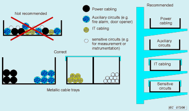
Fig. 19 Separation of Cables in Wiring Systems
Where power and data cables are installed within the same containment system or within close proximity to each other, suitable segregation shall be used. For guidance on segregation, refer EN 50174-1 : 2018.
NOTES
1 Category 1 Circuit — A circuit (other than a fire alarm or emergency lighting circuit) operating at low voltage and supplied directly from a mains supply system.
2 Category 2 Circuit — With the exception of fire alarm and emergency lighting circuits, any circuit for telecommunication (for example, radio, telephone, sound distribution, intruder alarm, bell, call and data transmission circuits) which is supplied from a safety source.
3 Category 3 Circuit — A fire alarm circuit or an emergency lighting circuit.
5.17.1 Where a wiring system is located in close proximity to a non-electrical service following conditions both shall be met:
a) the wiring system shall be suitably protected against the hazards likely to arise from the presence of the other service in normal use; and
b) protection against indirect contact shall be provided.
5.17.2 A wiring system shall not be installed in the vicinity of a service which produces heat, smoke or fume likely to be detrimental to the wiring, unless protected from harmful effects by shielding arrangement so as not to affect the dissipation of heat from the wiring.
5.17.3 Where a wiring system is routed near a service liable to cause condensation (such as water, steam or gas service), precautions shall be taken to protect the wiring system from deleterious effects.
5.17.4 Where a wiring system is to be installed in proximity to a non-electrical service it shall be so arranged that any foreseeable operation carried out on either service does not cause damage to the other.
5.17.5 Any metal sheath or armour of a cable operating at low voltage or metal conduit, duct, ducting and trunking or bare protective conductor associated with the cable which might make contact with fixed metalwork of other services shall be either segregated or bonded to it.
Electrical Installation for Lifts shall conform to IS 1466 (Part 2) and for escalators shall conform to IS 4591 along with the statutory requirements mandated by respective state/UT.
NOTES
1 Scope is limited to provision of point of supply to lift machine related equipment and illumination with power outlet at every floor level in lift shaft.
2 ‘Lift’ and ‘Elevator’ shall be treated as synonymous.
Cables used for electric supply points for light and power outlet within lift shaft shall be armoured. Size shall be as specified in the manufacturer’s requirement and Lift Rules but shall not be less than 2.5 mm2.
For lifts, cables used for electrical supply points (light and power outlet) in the lift shaft shall be of appropriate category of FS type as per IS 17505(Part 1).
The electric supply for the lifts shall be separate from other building services, shall have separate circuits from the main switchrooms and shall be taken through armoured cables separately through respective lift shafts. The route of the armoured cable shall be safe from fire. Further there shall be separate cables for power supply and lighting from meter room to machine room and shall have independent protection. (Specific rules of respective state shall be adhered to).
Both power cable for machine equipment and lighting load (light and power outlet points at each floor) cable shall be routed through lift shaft to the machine location first. Supply to the system of both cables shall be controlled
SP 30 : 2023
from the location of machine in such a way that cable providing supply return through shaft for light and power outlets.
NOTE — Lift shaft shall not be used for electrical installation of any other service.
Machine room and all other rooms containing lift equipment should be provided with adequate illumination with lux level not less than 200 and with a switch fixed adjacent to the entrance. At least, one socket outlet suitable for hand lamp or tools should be provided in each room.
To avail safety, ease of operation, trouble free service, power quality and redundancy of electric supply, appropriate sectionalizing of electrical distribution from point of source of supply to utility points is absolutely necessary. Following points provide guidance in this regard.
It is an important tool and basic requirement in electrical design to coordinate various components of distribution system of wiring installation for satisfactory and safe working. It also helps to trace faults, plan carrying out modifications, additions and alteration in the existing installation. Therefore, it shall form inherent part of documentation of any electrical installation to be possessed by owner and maintained as a record. It shall be duty of electrical contractor to display the diagram at respective distribution location and handover the drawings to the user/owner for his record.
It is always convenient to start preparation of SLD from the utility points and ending to main supply source. This facilitates deciding capacities of different components.
SLD shall show following components starting from point of supply as per applicability:
a) Main control switch at point of supply;
b) Main distribution panel/DB;
c) Mains;
d) Sub-distribution switchboard;
e) Sub-mains;
f) Distribution and sub-distribution Boards (DB);
g) Circuit mains/branch circuit; and
h) Switch board controlling outlet points.
Switch Board-
Total Number of points and load
(for example, 10 points of 240 W each)
Circuit main-
Size and number of conductors in mm2
(for example, 2 × 2.5 + 1 × 2.5 Earth/CPC)
DB-
Single (SP)/three phase (TP) and ways
Power/Lighting
MCB B/C/D, No. of poles and Amp
RCD- Poles, Amp, sensitivity mA
for example, 8-way SPN LDB
1 No. 16A DPMCB B series in coming
5 Nos. 6A SPMCBs B series outgoing
2 Nos. spare ways
Load on each circuit
Total load on DB
Sub-main- Size and number of conductors
for example, 2 × 4. 0 + 1 × 4 Earth
Control switch- SP/TP and ways
MCB B / C / D, No. of poles and Amp
32A DP MCB B series
Mains- Size and number of conductors
for example, 4 × 6. 0 + 1 × 6. 0 Earth
Main switch- No. of poles, Amp B/C/D
for example, 32A TPN C series MCB
Alphanumeric Identification shall be assigned and shall be explicitly shown on SLD for:
a) Switch-boards;
b) Distribution boxes;
c) Circuit-mains, sub-mains, mains; and
d) Electrical panel boards and switchgears on SLD.
6.2.1 It is important to label the components of wiring installation with the appropriate Identification assigned to them as per SLD (see 6.1.3).
6.2.2 This step shall be executed in such a way that all points of distribution system could be traced with incoming source and outgoing destination. For example, within switch board of point wiring, circuit numbers shall be labeled indicating circuit feeding supply to the switch-board etc.
6.2.3 The step shall be completed before the installation is handed over for use.
Part of wiring starting from Switch-Board (including switch-board and accessory) and terminating into outlet accessory of utility point like lamp-holder, ceiling-rose, plug-outlet up to 6 A capacity is generally treated as point wiring for lighting.
NOTE — For the purpose of lighting fixtures, point wiring may be extended from one outlet to required number of outlets as per design but termination/extension must be through an appropriate accessory.
Final circuit starting from DB feeding supply to power outlet of 16 A plug socket is generally treated as power point.
Size of wires shall not be less than 1.5 mm2 copper for lighting and 2.5 mm2 for power (see Table 6). This includes earth wire wherever mandatory (see 6.3.3).
NATIONAL ELECTRICAL CODE OF INDIA
Proviso under Regulation 41(XIV) of CEA Safety Regulations 2010 gives relaxation from providing earth for apparatus consisting of wall tubes, light-brackets, ceiling-fans etc. It also excludes hand-lamps or portable apparatus unless provided with earth terminal and class-II apparatus/appliance having voltage less than 250 V.
SP 30 : 2023
NOTE — If earth terminal is provided on the apparatus/appliance by the manufacturer, provision of suitable accessory to terminate protective conductor shall be made.
Considering that not more than one circuit shall feed supply to switchboards, the total load of number of light, fan, 6 A plug outlets shall not exceed 30percent of the maximum current carrying capacity of the circuit main as per 5.5 and Annex C or 1 000 W or 24 points, whichever reaches its limit first.
Table 12 may be referred for assessing load on a lighting switch-board.
(Clause 6.3.4.1)
| Sl No. | Connected Device on the outlet of point wiring | Load consideration |
| (1) | (2) | (3) |
| i) | Light point | 50 W |
| ii) | Fan point | 75 W |
| iii) | Power outlet 6A | 100 W |
| NOTES | ||
| 1 Conventional light point includes incandescent lamps/Tube light with ballast of any types. For energy saving LED or equivalent, lesser wattage may be considered. In non-residential establishments where series of lights are controlled by single switch, actual load shall be taken into consideration. | ||
| 2 Fan shall include all types and sweeps. | ||
| 3 If actual rating of appliance is known, it may be taken into consideration subject to envisaged changes. | ||
Table 13 gives general guidelines for power load calculation. It may be considered as envisaged minimum load of appliance. However, where an appliance of higher power rating is to be connected, actual rating shall be considered.
Table 13 Determination of Load of Power Points
(Clause 6.3.4.2)
| Sl No.(1) | Commonly Connected Devices on the Outlet of Power Point(2) | Load Consideration in W(3) |
|---|---|---|
| 1) | Bathroom | |
| a) Storage type water heater | 2000 | |
| b) Instant hot water geyser | 3000 | |
| 2) | Dry balcony | |
| a) Washing machine | 2000 | |
| b) Dish washer | 1500 | |
| 3) | Kitchen | |
| a) Electric hot plate | 2000 | |
| b) Induction hot plate | 2000 | |
| c) Electric oven | 2000 | |
| d) Microwave | 2000 | |
| e) Mixer/grinder | 500 | |
| f) Fridge | 500 | |
| g) Toaster/kettle | 800 |
| Table 13 (Concluded) | ||
| Sl No.(1) | Commonly Connected Devices on the Outlet of Power Point(2) | Load Consideration in W(3) |
| h) Air Fryer | 1500 | |
| j) Kitchen exhaust hood | 700/1000 | |
| 4) | Other | |
| a) A.C. 1TR/1.5 TR/2 TR | 1250/1500/2000 | |
| b) Room heater | 1000 | |
| c) Computer | 150 | |
| d) TV | 100 | |
| e) Iron | 800 | |
| f) EV charging | 1000-3300¹⁾ | |
| ¹⁾ Actual requirement may be checked with OEM. | ||
Following points shall be observed while making connections within switch boards:
a) Switches shall be provided on line conductor/phase wires only;
b) Supply of line conductor to the plug socket on board shall be given through switch and right side terminal (seen from front) as per convention and neutral shall be connected left terminal directly;
c) Care shall be taken so that neutral doesn’t isolate at places, other than two pole switch (SPN) which operates simultaneously on both terminals;
d) No part of exposed live part of conductor, solid or stranded (stripped off insulation) shall remain open outside the area of terminal;
e) Cross sectional area of conductor used for inter connections within board shall not be less than cross sectional area of circuit mains; and
f) Within switch-board, there shall not be any joints except at terminals.
See 6.2
Size of conductor shall depend on the installed load and its diversity/simultaneous demand. For general guidelines, Table F-1 of Annex F may be referred to assess simultaneous demand.
Depending on type of load and the power factor, VA shall be considered to assess required current carrying capacity.
Cross sectional area shall be worked out as per the guidelines under 5.5 to 5.8.
For availing supply redundancy use of ring circuit may be made with appropriate protection and due precaution of particular phase.
In single phase distribution, care shall be taken to optimize the load balance on three phases to avoid neutral current.
97
While terminating care shall be taken that no part of conductor core (solid/stranded) shall escape outside the cross section of terminal. Generally, conductors up to 32A current carrying capacity do not need special preparation (leads soldering/lug crimping). However, if conductor is considered to carry current above 32A, its terminating leads shall be specially prepared.
While installing UPS/Inverter, it shall be provided with back-feed protection as per IS 16242-1 : 2014/IEC 62040-1: 2008 and following points shall be observed.
i) There shall be provision of two pole transfer switch (preferably, solid state) in the UPS/Inverter to isolate both line and neutral, so that after power supply interruption from the utility’s distribution network, it remains totally isolated from the UPS/inverter power output and no back-feed/hazardous energy is transferred to the input power terminals of UPS/Inverter and no Electric shock hazard exists after 1 s at this juncture.
ii) For every outgoing wiring circuit, connected to the output supply of UPS/Inverter, the neutral shall be separately run and utmost care shall be taken that no looping occurs at any point with the neutral of any other load circuit and shall not form a part of inverter load. The figures given below show the incorrect and correct methods to use UPS/Inverter system with battery back-up as per IS 732 : 2019.
iii) When UPS systems have galvanic isolation through Isolation transformer or by some other methods, output neutral of UPS shall be earthed with separate protective conductor. This helps to avoid stray noise
in the earth and neutral affecting the sensitive loads. The output a.c. circuit shall be referenced to the protective earth of the equipment in which UPS is intended to operate. The bonding of protective earth and neutral conductors applies to all modes of operation of the unit. The physical bonding point may be external to the UPS as per IS 16242 series of standards.
iv) Body earthing (protective earthing of UPS) - Extraneous conductive parts of UPS which might assume a hazardous voltage in the event of a single insulation fault, shall be reliably connected to a protective earthing terminal within the UPS.
v) It is advisable to consider neutral conductor of adequate cross section as most of the loads on UPS are SMPS or electronic loads which cause harmonics..
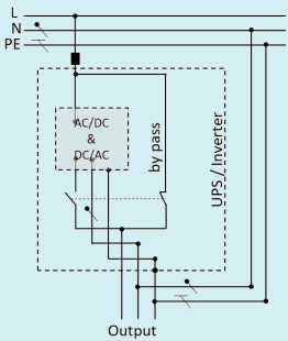
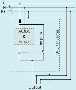
Fig. 20 Block Diagram of Wrong Connection of Inverter Leading to Back Feed of Output Power Towards the Input
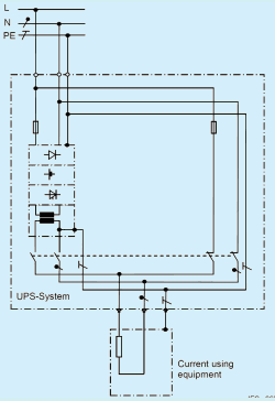
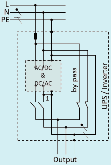
Fig. 21 Output Side of the Inverter Neutral Earthed Inside the Inverter to The Earth Terminal Inverter/UPS with 2 Pole Isolation at Inverter Output and at Bypass Circuit (Isolation Ensured for Line and Neutral)
Circuit from DB protected by over-current and short circuit protective devices, feeding supply to current using appliances and power outlets, directly or through branches and without any further disconnecting arrangement by fuse/MCB (for example, cables providing supply to switch-board from DB etc.)
For the purpose of convenience and redundancy, it is recommended that there shall be separate/independent circuit/s of lighting load for:
a) all rooms with door where entry can be restricted (attached balcony/terrace may be included);
b) common areas like passage, verandah; and
c) Toilets.
Switch board providing supply exclusively for plug outlets may be provided with separate circuit.
Circuit design of non-residential premises may be done considering following factors:
a) enclosed area considering access;
b) maximum allowable load to suite the assessed current carrying capacity of circuit mains;
c) utility - light/fan/power outlets; and
d) routes – ceiling/false ceiling, walls/partitions/under floor raceways.
There shall be separate circuit for each area as mentioned in 6.4.1. For all air-conditioners and water heaters, there shall be provision of independent circuit. Load on one single power circuit shall not exceed 3kW and number of 16A power outlets shall not be more than two (for example, for an equipment with load 3kW such as instant hot water geyser is connected on a power outlet, there shall not be second power out let on the same circuit).
Design of circuits shall be depend on premise area (a circuit shall not enter in to premises area for which entrance is through another door/area). Other factors to be considered shall include load of appliance/equipment, supply redundancy with minimum outage in case of fault etc.
Essential loads shall be sorted and such circuits shall be bifurcated to avail standby source of supply. Depending on necessity further categorization and sorting shall be done for required back-up time period. See Table G-1 under Annex G.
Distribution box is an important component of electrical installation which streamlines electrical power from its source to utility point with an arrangement for wiring protections at different levels. Electrical design shall comprise distribution boxes of appropriate type at appropriate locations. Feeding of single phase DB from another single phase DB shall be avoided.
Depending on source of electrical supply (single phase or three phase), quantum of electrical load area and plan of building/premises, distribution boxes of single pole neutral (SPN)/three pole neutral (TPN) with required number of ways (two, four, eight, twelve, twenty-four etc.) shall be installed. Options of three phase incoming and singlephase outgoing or three-phase incoming and three-phase/single phase outgoing are available.
Distribution boxes are available comprising protection provided in the form of fuses, miniature circuit breakers (MCB) and moulded case circuit breaker (MCCB). Both types of DBs (Fuse and MCB/MCCB) are available in single phase (SPN) as well as three-phase. (TPN). In MCB DBs there is provision to incorporate MCB/MCCB for incoming supply. However, for traditional DB with fuses, it is necessary to install separate switchgear for incoming supply, usually, metal Clad/Iron Clad DP/TP switch with fuses and neutral link.
1 Distribution of old conventional fuse box DB is not recommended.
2 High risk is involved in replacement of fuses.
Though replacement of fuse wire is an easier and economic option as compared to replacement of MCB, availability of appropriate size of fuse wire and of qualified electrician capable of choosing the correct size to suit wiring installation. It may be noted that CEA Regulations does not permit non-qualified person with no work permit issued by government to perform such task. Under these circumstances of non-availability of correct fuse wire and non-availability of qualified person to the task, the situation may become accident prone.
6.6.3.1 MCBDBs shall conform to IS 13032. They are available with various designs and mounting arrangements such as flush mounted, surface mounted, etc. with covers or hinged doors of different types and of different materials to suit the situation, accessibility and visibility requirements for MCBs.
6.6.3.2 In TPN DBs, individual phase isolation facility is also available where two pole RCDs/RCBOs can be fixed for each phase so that in case of fault in one of the phases, supply of faulty phase isolates without affecting supply of other phases.
6.6.3.3 DBs are available with facility to fix MCB/MCCB/RCD/RCBO and with required number of ways on incoming side. DBs are also available with provision to fix MCCB both on incoming and outgoing side.
6.6.3.4 The bus-bar, neutral link and earth link shall be as specified in relevant Indian Standard to carry current under normal and fault condition the links shall have sufficient number and size of terminals to accommodate number of cables with different cross sections.
6.6.3.6 Space within the DB shall be sufficient to accommodate the number and size of cables with required loops without over-crowding.
Following points shall be taken into consideration while fixing location of distribution box:
a) There shall be a load center to limit length of circuit mains and voltage drop;
b) It shall be installed in common areas where there is no hindrance to reach and operate especially during emergency conditions;
c) suggested height shall be above ground such that it is beyond the reach of children. But the replacement/ reset of protective devices shall be in accessible position without aid of any tackle, for example, at an average height between 1.8 m and 2.1 m;
d) The distribution box shall not be located at structural expansion joints of the building.
DBs may be selected as TPN type primary/sub-DB, through which supply is provided to local/secondary/final DB which may be TPN or SPN, depending on the scope and stages of distribution design.
While selecting DB following points may be taken into consideration:
a) Safety level, (also see footnote 2 of 6.6.2);
b) 6.6.1 - Phases, ways;
c) 6.6.2 - Fuse, MCB;
d) 6.6.3 - Enclosure designs;
e) 6.6.4 - Location;
f) sustainability under respective environment;
g) Protection against external influences, IP class (see 5.4); and
h) shall have easy access while installing and making internal connections (for example, sufficient spacing to accommodate wires, adequate terminal with minimum contact resistance etc.
DB and all its circuits shall be labeled with appropriate identification mark (see 6.2).
7.1 All material used in wiring installation shall conform to relevant national and international standards.
7.2 Selected material shall have property to sustain under respective environmental, working conditions, effects of external influences and shall be safe and functional throughout its desired service life.
7.3 Adequate precautions related to transportation, handling and storage shall be taken. In case any damage occurs, such material shall not be used before confirming its technical parameters.
7.4 It is advised that in project works, sample(s) from the material brought on site may be tested from the accredited test laboratory and records may be maintained.
7.5 It is recommended that the basic material and its accessories/different components forming a unit of wiring system shall be from same manufacturer, Also, there shall not be use of multiple brands/type of same manufacturer for any material component used on particular site. For example:
a) in conduit system, conduits and its accessories like junction boxes, elbows, tees, etc.
b) in PVC trunking system, trunking and its accessories;
c) in cable ladder and tray system of all sections, supports, accessories etc;
d) for switchboards, switches, sockets, fan regulators, dimmers, blanking plates, boxes, and cover-plates; and
e) for distribution boxes; MCBs, isolators, RCDs, SPDs, blanking plates etc. and the fit in boxes.
All circuits shall be provided with basic protection to safeguard them from over-current and short-circuit faults. It is important and mandatory to provide protection against leakages with RCDs. Adequate protection against over-voltages/surge may also be provided. Within wiring installations, the number, rating, and locations shall be so chosen that it provides adequate safety against electric shock and fire hazard to safeguard life and property as well as to avoid false tripping and un-neccessary outages.
NOTE — It is pertinent to provide the protective devices according to safe current carrying capacity assessed with respect to cross sectional area of conductor under particular situation and reference method of installation (see Annex B and Annex C), For example, as per Table B-1 current carrying capacity of 2.5 mm2 Cu conductor, if installed as per reference method A2 is 18.5 A and if installed as per Reference Method D1 is 29A. This indicates that the overload rating of protection shall be different for method of construction.
Fuses shall conform to IS 60269 series of standards. For SD/SDF IS/IEC 60947-3 shall be referred.
Fuse wire embedded between two terminals in porcelain cutout is an old, conventional and economical option. It is important to use correct size/gauge of fuse wire made of correct material/alloy having required characteristics to heat up and melt/fuse in prescribed time when current exceeds nominal value in the circuit (see footnote of 6.6.2)
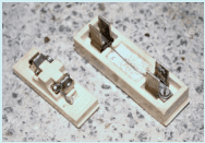
Fig. 22 Porcelain Cut-Out With Fuse Wire
SP 30 : 2023
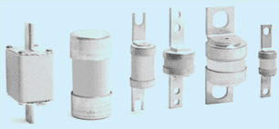
Fig. 23 Blade/Bolt/Cartridge Type HBC Fuses
High breaking capacity (HBC) type fuses, also, known as high rupturing capacity (HRC) fuses are suited to work where high fault energy is required to be restricted along with the electromagnetic stresses which may cause mechanical damages to the current carrying components. Such types of fuses are replaced once operated. Some HBC fuses are also provided with an indicator to display condition of fuse. These fuses operate very fast and have very high short circuit current handling capacity as compared to circuit breakers. Such fuses are, therefore, also used for backup/secondary protection.
Linked switches ‒ DP or SPN/TP/TPN along with suitable fuse(s) on phase(s) and a link for neutral have been used traditionally to provide protection against overload and short-circuit along with isolation of current. These are available with rewirable and HBC fuses.
Such types of control switches are available in different varieties with iron clad/metal clad enclosure, suitable to mount on fabricated frame/skeleton type panels and without enclosure suitable for fabricated cubical panels.
While using such type of control switch gears, it shall be kept in mind that such types of protective devices are manually operated. There is no tripping mechanism. During fault, only fuse(s) of faulty phase(s) blows. Remaining phase(s) continue to supply power. This may lead to unbalancing of load/supply.
Miniature circuit breakers (MCB) have replaced traditional fuse-based protections. MCBs have many fold advantages like compactness, ease of resetting, identical sizes for large range of current capacities up to 125 A, ease of erection and maintenance, facility to choose suitable tripping characteristics depending on type of load, etc. MCBs shall conform to IS/IEC 60898-1.
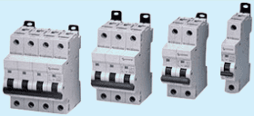
Fig. 24 MCBs
MCBs are available in single pole (SP), double-pole (DP), single-pole neutral (SPN), triple pole (TP), triple-pole neutral (TPN) and four pole (FP) types. It shall be noted that where ‘N’ appears on a pole that does not provide any particular protection against overload or short circuit, provides isolation. Double pole in place of SPN or four pole in place of TPN are used when there are chances of large current flow in neutral due harmonics or unbalanced loading.
MCBs are available with different instantaneous tripping range as shown in Table 14A. Based on the table, suitable MCB shall be selected to avoid nuisance tripping suitable for type of load having inrush of current/surge.
| Sl No. | Type | Range |
| (1) | (2) | (3) |
| i) | B | Above 3 In up to and including 5 In |
| ii) | C | Above 5 In up to and including 10 In |
| iii) | D | Above 10 In up to and including 20 Ina) |
| a) For special cases, value up to 50 In may also be used. | ||
Generally, for resistive loads, ‘B’ type MCBs are suited. But for appliances such as air conditioners and water pump motor, ° C ° type MCB shall be provided. For inductive loads, ° C ° type MCB may be used. For devices with very high inductive load, SMPS power supply units, UPS, etc., ° D ' type MCB shall be used.
Isolators and MCBs look similar. It may noted that an isolating device is manually operated and does not provide any protection against overload and short-circuit faults. Its use is not advisable, especially, when there is no nearby back-up circuit protection. Under such circumstances, there are chances of welded contacts leading to fire.
SP 30 : 2023
Surge Protective Devices are intended to limit surge voltages and divert surge currents. SPDs shall conform to IS 16463-11/IEC 61643-11.
As per the tests, SPDs are classified as Test Class I/[T1], Test Class II [T2] andTest Class III [T3]. Other parameters include one/two ports, outdoor etc.
Under specific conditions, provision of SPDs shall be made in electrical systems and sensitive equipments to protect from various over-voltages such as lightning surge, switching surge, temporary over voltages and impulse currents during lightning and switching surges.
Selection of type 1/type 2/type 3 SPD or their combination and location depends on various factors. Consider the following arrangement:
a) If there is no lightning conductor/grounded metal structures on building or in the vicinity ‒ Type 2 SPD may be provided at incoming circuit breaker/main panel.
b) If lightning conductor/grounded metal structures is provided on building/installation or at nearby area Type 1 and Type 2 SPDs may be provided at incoming circuit breaker/panels
c) If the structure is supplied by an aerial line considering risk of direct flash on the line ‒ Type 1 or combined Type 1and Type 2 SPD shall be provided.
d) If distance between main panel (fitted with Type 1 and/or type 2 SPD) and the sensitive equipment is more than 10m - Type 3 SPD near sensitive equipment shall be provided.
NOTE – For detailed information about selection of SPD, IS 16463-12 may be referred.
Within the distribution specific location intended for particular class of SPD, (i.e. origin of installation or in the main distribution assembly, close to installation/equipment) shall be observed and shall be available for inspection. Where situation requires use of more than one SPD proper coordination shall be maintained.
NOTE — For more details, refer 5.3.5 of IS 732 : 2019.
Residual current device (RCD)/residual current circuit breaker (RCCB) shall conform to IS 12640 (Part 1)/IEC 61008-1. These devices are intended to be operated by uninstructed persons and designed not to require any maintenance.
Earth leakages and electric shocks pose threat to human beings and livestock. Under the context RCD intend to provide protection against indirect contact and exposed conductive parts of the installation connected to an appropriate earth electrode. This device may also be used to provide protection against fire hazards without operation of over current protective device.
These devices are intended to be used for household and similar uses.
Reg. 42 of CEA (Measures related to Safety and Electric Supply) Regulations1) mandates with respect to provision of protective devices against the hazard of earth leakages depending on load. Accordingly, it is obligatory to make provision of RCD2) for installations not exceeding3) 250 V, with a limit of sensitivity4).
As per the latest amendment (Amendment 2015), this provision was made applicable for appliances/equipments rated for 2kW and above (from previous threshold of 5kW load). Amendments are under consideration with respect to sensitivity, voltage level, load and nomenclature of the device.
The present nomenclature of the device under CEA Regulations is Earth Leakage Protective Device. Renaming the Residual Current Device (RCD) is under consideration. Previously, ‘ELCB’ was used for voltage operated type device with two earth terminals for connection of earthing terminal of installation and for connection to earth electrode. The device had some drawbacks.
Applicability to voltage level as per IS12640 (Part 1)/IEC 61008 : 2012 is under consideration.
As mentioned under CEA Regulations 2015, sensitivity is 30 mA for domestic installations and 100mA for other installations considering the safe limit for humans.
Provision of RCCBs with sensitivity of 30mA shall be made for all household and similar installations for load of 1kW and above, with voltage levels up to 440 V and 125 A..
NOTE — As per CEA Reg. 2015, existing threshold exempt limit for load is up to 2kW, revision of decreasing load to 1 kW is under consideration. It is recommended to exempt load limit for providing additional safety towards complete elimination of shock hazard.
Provision of RCCBs shall be made at suitable locations within wiring installations such that in case of fault, supply of only that particular section of wiring installation is deflected and investigation to clear the fault is restricted to limited section making procedure faster and easier.
Residual current breaker with overload and short circuit protection (RCBO) shall conform to IS 12640 (Part 2)/ IEC 61009-1. This device is intended to be operated by uninstructed persons and designed not to require maintenance.
This device provides protection from harmful leakage current of the order of 30mA and above with integral protection against over-current and short-circuit. It is useful for wiring installations in household and similar places, to protect people against indirect contact with exposed conductive parts of installation. This device is suitable for voltages up to 440V, rated current 125A and short circuit breaking capacities up to 25kA.
NOTE — For protection against shock, from extraneous conductive part, it is necessary to connect it to earth through protective conductor.
This device can be located suitably in DBs within distribution network requiring both functions at that particular location. The location at main supply source may be selected considering the possibility of complete blackout in premises.
Before installation, following points shall be considered:
a) It is easier to use single device for two functions instead of two separate devices as it saves space and is economical;
b) Terminations and connections are required for one device which help in reducing contact losses and number of inspection points;
c) The devices trips the supply due to either of the fault and affect complete portion which, in some cases, is undesirable;
d) Where possibility and frequency of one of the faults is more, under such cases, combined device prove disadvantageous; and
e) Tripping of device does not indicate the type of fault ‒ earth leakage or overload/short-circuit and hence, is not helpful for fault finding.
In the wiring Installations of industrial or similar purposes, where there is requirement of making and breaking a circuit of higher current rating and higher short-circuit current rating, Circuit breakers shall be used. Circuit breakers shall conform to IEC 60947 series of standards. The breakers also have adjustable setting for overload and short-circuit.
According to IS/IEC 60947-2, category A breakers do not have deliberate time delay in the operation of the instantaneous short-circuit magnetic tripping device. The breaking occurs before first peak of the current waveform is reached. Category B breakers have ability to withstand one or more cycles and hence, helps to discriminate and maintain tripping sequence.
Circuit breakers must be capable of safely interrupting the maximum potential of short circuit current at their location in the circuit. Hence, they shall have breaking capacity higher than potential short circuit current and shall be suitable for add-on auxiliary functions, if required.
NOTE — Correct fault level calculations are important to choose breaker with precise breaking capacity. It shall be noted that cost of breaker increases with breaking capacity.
In wiring installations, breakers are used prior to downstream LV distribution and one of the type ‒ MCBDBs, MCCBs and ACBs. It is recommended to check manufacturer’s specifications and the design requirements prior to use of MCCBs and ACBs in wiring installation.
Moulded case circuit breakers (MCCB) generally come under category A. They are preferred in downstream applications. Due to technological advancements, breaking capacities of MCCBs (though not comparable with higher limits of ACB) are improving and hence, up to particular range, design parameters of both with ACBs and MCCBs are similar.
Cost wise MCCBs are cheaper than ACBs. Its compactness may advantageous but from the point of view of termination of higher size of cables it may cause some inconvenience and may require spreaders increasing contact resistance.
MCCBs are typically available up to 3200 A, but its use at lower current rating is found to be more effective. Frame size of MCCBs may not be identical and hence point shall be considered while designing panel.
It may be noted that feature of rated short time withstand current (category B) is, generally, not available in MCCB.
Capacity to clear number of faults is relatively less.
Due to internal maintenance, recurring cost is negligible.
The rated current (I ) for Air Circuit Breakers (ACB), typically, ranges from 630 A to 6300 A. Under category B, ACBs have high short-circuit withstand capacity ( I C W ) and rated breaking capacity ( I C U ) , hence, are suited upstream/on incoming side. Short-circuit withstand time of up to 1 s helps providing discrimination in the system.
A switchboard is an assembly consisting of switching devices along with associated control, measuring, indicating, and protective equipment for distribution of electric power.
Based on area of application, switchboards are classified into different types and shall conform to IS/IEC 61439 series of standards for voltage upto 1000 V a.c. or 1500 V d.c.
Switchboards can be of wall-mounted or floor-mounted structures clad in metallic or non-metallic enclosure. The one or more incoming/outgoing feeders are either of fixed or withdrawable type.
These are designed to meet the required dielectric withstand properties and insulation co-ordination based on location of the installation as per the over-voltage category and pollution degree of the environment at the installation.
These are meant to be commissioned in both indoor and outdoor environments meeting the required climatic conditions like ambient air temperature, relative humidity, altitude, condensation and effects of UV radiation.
Switchboards shall have a minimum degree of protection of IP 2X with ‘forms of internal separation’ ranging from ‘form 2a to form 4b’.
Typical switchboards come with rated current of the assembly ( I n A ) from 63 A to 6300 A and short-circuit withstand strength between 10 kA and 100 kA.
All accessories, unless mentioned, shall be rated for 250V, 6A. All accessories shall be designed and constructed so as to conform to relevant standards and shall be suitable1) under particular environment/location to sustain external influences. The material used may be plastic2), metal or combination which suits the application.
Under hazardous conditions, material shall conform to respective norms to prevent hazard, for example, at fire prone sites, locations exposed to flammable/explosive dust, accessories along with their enclosures shall be flame proof and shall have ingress protection etc.
Plastic is a broad term and under family of ‘Plastics’, categorization is made depending on specific properties required (for example, thermoplastics, phenolic moulded resins, thermosetting resins etc.) with respect to particular function.
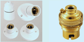
Fig. 25 BC Type Pendent, Angle, Batten and Metal Lamp Holder with Earth Terminal
Free Standard provided by BIS via BSB Edge Private Limited to self-developer - bengaluru(shivaprasad.safare@tandemloop.in) 49.204.144.146.
SP 30 : 2023
In wiring installations, the accessories shall be so installed as to suit the user requirements and shall function in reliable manner without causing any danger to persons or surroundings.
NOTE — For more information, see 12.
Various accessories which are generally used are as under:
a) lamp holders;
b) Ceiling roses;
c) Connectors;
d) switches – 6 A/16 A;
e) plug sockets – 6 A/16 A or combination;
f) Plug tops – 6 A/16 A; and
g) Boards/boxes/plates.
Lamp holder is a means of supplying current to a lamp and providing mechanical support to the lamp. Lamp holders shall conform to IS 1258.
Lamp holders are of two types ‒ Bayonet type/Bayonet Connector (BC) and Edison Screw (ES) type.
These holders are identified by ‘BXX’ for Bayonet type and ‘EXX’ for Edison type. The ‘XX’ denotes the diameter in mm of the lamp cap (for example, B22 or E27. In case of Edison type, lamp holder diameter across the peaks of the thread on the male is taken.
Standard rated current for B15 and B22 holders shall be minimum 2 A. In case of requirement of higher ratings, manufacturer’s specification shall be referred. Lamp holders shall not be used for external electrical installation without conforming to required IP class.
Fig. 26 Edison Screw Type Lamp Holders
Before installation, care shall be taken to select lamp holder suitable to particular lamp cap. The style Batten/ Angle/Pendent type or other types mentioned under standard may be selected depending on the location or required position of lamp. B15 lamp holders shall not be used in circuits with ignitors and B22 shall be used subject to approval by the manufacturer. Exterior material of Lamp Holder may be plastic, ceramic or metal. Usually in fixed wiring installations, plastic material is recommended. For plastic lamp holders, a protective shield similar to skirt shall be provided to avoid accidental contact with lamp cap. Metal lamp holders are used for decorative lamp fixtures. For such holders, earth terminal or other means of earthing shall be in effective electrical contact with all exposed non-current carrying metal parts. Lamp holders with integrated switch shall conform to requirements specified in the respective standard.
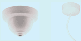
Fig. 27 Ceiling Roses
Ceiling Rose is a means of supplying current from fixed wiring to a pendent lamp holder or other movable accessory like bell push or a lighting fixture, ceiling fan, bell/buzzer or similar apparatus with a flexible wire cord. It shall conform to IS 371.
All ceiling roses shall be provided with earth terminal and it shall be visibly distinguishable.
Location of ceiling rose shall be close to the intended location of appliance to avoid loose hanging wires.
Ceiling roses are intended for use with cables complying to IS 694. In three-plate ceiling rose, third plate may be used for looping the wire. Ceiling-roses may be intended to sustain mechanical load by means of flexible cord complying to IS 694. Before using the ceiling-rose for such application, manufacturer’s specifications regarding safe working, mechanical loading limit and method of fixing to mounting surfaces shall be checked (see 9.1.2.6).
Switch is a wiring accessory which is used for making or breaking the current supply to the outlet/utility point and shall comply with IS 3854.
Switches generally used in wiring installations can be broadly classified depending on:
a) Poles — Single pole/two pole;
b) Ways — One way/two way;
c) Activation — Tumbler/rocker/push button/rotary/cord-operated;
d) Application — Surface type/flush type/modular;
e) Method of Installation — Cover removable by disturbing conductors/without disturbing conductors;
f) Operation — Manual/remote; and
g) With/without indicator.
SP 30 : 2023
Switches are, generally, available for current rating ‒ 6A/10A/16A/32A and are single-pole/two-pole to suit the requirement as per the design and load.
Current rating of switch shall suit the load, its type and size of conductor. For point wiring of light and fan circuits, 6A switch shall be used. For plug points on board or independent plug point, switch may be of capacity 6A/10A. For power points, minimum 16A switch shall be used.

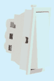
2

3
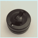
4

5
Fig. 28 Different Types of Switches
Plug and sockets with/without earth contact shall conform to IS 1293, which is intended for household and similar purposes and applicable to 250V and rated current up to 16A.
NOTE — In view of prevalence of two pin plugs and socket outlets in household purposes, it is necessary to use standardized plugs. However, the user must ensure proper earthing practices in line with IS 732 and IS 3043. Two pin plugs are intended to be used only for class II appliances.
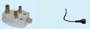
Fig. 29 Three-Pin Plug Type D And Two-Pin Plug Type C
It is an accessory having pins designed to engage with the contacts of socket outlet, and incorporating the means for the electrical connection and mechanical retention of flexible cables.
Plugs are classified according to:
a) current rating 2.5 A, 6 A, 16 A;
b) without earth pin (for 2.5A and 6 A) – limited to class II appliances (non-rewireable plugs only);
c) with earth pin (for 6 A, 16 A, 6/16 A) – all class I appliances;
d) rewirable, non-rewirable; and
e) type of terminals screw type and screw-less.
NOTES
1 In case of re-wirable plugs there shall be provision of grommet which prevents cutting/damaging insulation of wire at the point at entry/exit point.
2 IS 1293 may be referred for the latest provisions.

Fig. 28 6A 3 Pin, 6/16A Combined Socket-outlet
It is an accessory having socket contacts designed to engage with the pins of a plug along with terminals for the connection of cable(s)
NOTE — 16.5 mm pitch and 5 pin plug design is deleted from revised IS 1293.
Sockets-outlets are classified as with earth/without earth terminal, rating - 6A/16A or combined 6/16A, shuttered/ non shuttered, mounting - flush/surface; fixing - screwed/press-fit/modular etc.
1 It shall not be possible to engage a plug of Class I appliance with socket outlets exclusively designed to accept plugs for Class II appliances.
2 Generally, shuttered plug sockets shall be used. In case of un-shuttered sockets, its location shall not be within the reach of children. Plug boards at skirting level shall always be shuttered type.
The enclosure which is integral part of electrical accessory and provides protection in the form covers, coverplates, boxes intended for mounting or suspension of luminaries shall conform to IS 14772.
Enclosures can be classified according to material – metallic/insulating; method of installation – flush/surface; location of installation – walls/ceiling/flooring; base of installation; in/on – masonry wall/concrete/insulated wall/ hollow wall; protection class etc.
Enclosure shall be suitable to use under the particular situation to provide mechanical protection, ingress protection, fire protection, shock protection, protection against corrosion/rusting etc. as per requirement. Boxes shall be of suitable size to accommodate accessories maintaining required clearance between terminals of accessories and rear plate of box, wire or leads. There shall be provision for earth terminal on the metal box.
Selection of enclosure shall be as per 8.5.1 and 8.5.2 on the basis of number of accessories/modules.
All boxes shall be firmly fixed. No gap shall be left between enclosure and the surface on which it is fixed. Electrical continuity wherever expected, in case of metal conduits and boxes shall be confirmed after installation.
This section gives guidelines for lighting fixtures for providing sufficient illumination, fans for providing adequate ventilation for human comfort and hygiene and other fixed appliances forming a part of wiring installations to be integrated with the system from the point of view of design, purpose, utility and safety within the premises.
Lighting fixtures are used with the lighting devices to provide adequate illumination. Lighting fixtures and their integrated parts shall conform to IS 10322 series of standards.
Lighting fixture shall be selected keeping in view the required functionality. Number and wattage of fittings shall be selected depending on required illumination level as per Table 4 of Part 8/Section 1 of NBC 2016. While selecting lighting fixture, factors of external influences and safety requirements as envisaged under IS 302 as well as energy conservation aspect shall also be taken into consideration.
NOTE — For further selection of Luminaries, Part 4/Section 1 of SP 72 may also be referred.
The means for fixing shall be capable of supporting a mass of not less than 5 kg. Where the mass of the luminaire is greater than 5 kg, it shall be ensured that the means for fixing is capable of supporting the mass of the luminaire.
As far as possible, the installation of fitting shall be near to the outlet point. However, if it is not possible to keep the outlet point near to the fitting, it shall be clipped properly so that it does not hinders the light.
Connection with lighting fixture shall be done with a two core or three core cord, when the fixture has an earthing terminal (see 6.3.3). Proper tightening of wire leads shall be done at terminals. No live part shall remain exposed and accessible.
NOTE — Cords to be concealed in hollow portions (for example, false ceiling) shall be provided additional protection of flexible conduits to protect them from external influences like rodents etc.
Depending on design parameters, more than one lighting fixtures may be grouped on one controlling switch.
Heat dissipation factor of luminaire and its integral part shall be taken into consideration while positioning, especially, in false ceilings, on wooden furniture or similar bases.
A cut out for flush type of fitting in the false ceiling or the similar base shall be made with a proper template of precise size. There shall be proper coordination in positioning with the sweep of fan so that no shadows occur.
NOTE — The false ceiling shall be capable of bearing the weight of the fitting to be installed. Generally, false ceilings are suitable for light weight fittings. In case of heavy/bigger size fittings, arrangement shall be made to support the fitting by a wire, rope or a similar material anchored in the structural part of the ceiling above false ceiling.
9.1.2.6 Suspended type Luminaire shall be fixed with proper accessories (for example, ball suspension plates, down rods/chain/bracket etc.), having sufficient strength to bear the weight of luminaire. If fitting is to be suspended through wire/cord, Table 16 shall be referred to check allowable weight.
Table 16 Maximum Permissible Weight on Cord
(Clause 9.1.2.6)
| Sl No. | Nominal Cross-sectional Area of Twin Cord mm2 | Maximum Permissible Weight kg |
|---|---|---|
| (1) | (2) | (3) |
| i) | 0.5 | 2.0 |
| ii) | 0.75 | 3.0 |
| iii) | 1.0 | 5.0 |
| iv | 1.5 | 5.3 |
| v | 2.5 | 8.8 |
| vi | 4.0 | 14.0 |
Ceiling fan shall have the functional to provide adequate ventilation. Ceiling fans shall conform to IS 374.
Selection of the fans shall be on the basis of technical parameters such as:
a) Sweep in mm (900/1050/1200/1400/1500);
b) Air delivery in m3/min;
c) Maximum power input in W; and
d) Service value in m3/min/W.
For proper ventilation there shall be provision of adequate number of fans at appropriate locations depending upon area. For reference, see Table I.1 under Annex I.
NOTE — In view of ‘Star Rating’ guidelines by Bureau of Energy Efficiency (BEE), updated specific norms shall be referred.
SP 30 : 2023
Updated Star rating index as per BEE guidelines as given in Table 17.
| Sl No. | Star Rating Index Calculation for Ceiling Fans | |
| Star Rating | Service Value for Ceiling Fans | |
| (1) | (2) | (3) |
| i) | 1 Star | >3.1 to < 3.6 |
| ii) | 2 Star | ≥3.6 to < 4.1 |
| iii) | 3 Star | ≥4.1 to < 4.6 |
| iv) | 4 Star | ≥4.6 to < 5.1 |
| v) | 5 Star | ≥5.1 |
NOTES
1 For the installation where there is limit for allowable temperature rise, 11.2.2 of Part 8/Section 3 of NBC 2016 may be referred.
2 For battery rooms, recommendations of manufacturer shall be followed.
a) Suspension System — The suspension of ceiling fan shall withstand tensile load of 1 000 kg and torsion load of 500 kg without breakage.
Some of the arrangements for suspension of fan to ceiling are shown below. Concealed type fan box is shown in Fig. 31. It shall be fixed in RCC slab by entangling the rod in the steel and embedding it in RCC slab during casting. Alternatively, where concealed type box is not needed, a bar without box shall be fixed. Post casting of slab, suspension arrangement is to be made with the use of truss member.
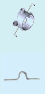
With respect to other fixed appliances, the cord connecting the power outlet and the appliance shall be insulated and sheathed. Its core shall contain colour coded earth wire. Cord shall be so arranged that it shall not entangle and damage. It shall remain at suitable distance from heat source. For water heater, washing machine, dishwasher etc. connected with the water pipes may be provided with independent Residual Current Devices (RCDs).
Before making beneficial use of the installation, it is recommended that verification shall be done as per 6 of IS 732 : 2019. Some of the important steps are given as under:
Before switching on supply, following check points shall be observed.
Finishing with respect to civil works carried out for electrical installation work. For example, openings in wall, false ceiling, core cutting, concealing, under floor raceways etc. are finished in approved/appropriate manner. Ducts, and shafts are provided with appropriate doors and at flooring level sealing is carried out with fire resistant material.
Electrical Installation shall not cause inconvenience and hindrance to any other utility service installed in the vicinity for its operation and maintenance activities and vice versa.
Installation of cables and wires shall be as per design and after completion, shall be suitable to survive under effects of external influences. Bunching within enclosure, for example, conduits and trunking shall satisfy space/ fill factor requirements. Colour coding and ferruling to identify circuit number shall be in an approved manner. There shall be no overcrowding within any switch board, DB, panel and there shall be no visible damages to insulation.
Terminations shall be firm. There shall be no loose contacts. All strands shall be properly inserted and lugs, where necessary, shall be of right material and crimped properly.
Adequate care shall be taken from the point of view of external influences. Supporting, joints, crossings fixing of accessories shall be firm and satisfactory. (See also 10.1.2).
Sizes, material and connections with earth terminals shall be made in a proper manner so as to maintain continuity.
Position, location and accessibility shall be appropriate from the point of view of operation, safety and maintenance. In case of modular accessories, vacant modules shall be plugged with blanking plates. Sockets at lower level shall be shuttered.
Locations, positions and accessibility shall satisfy required conditions from the point of view of operation, safety clearances and maintenance. Ratings, class/category, types, setting facilities of MCBs, RCDs, SPDs, MCCBs, other switchgears/breakers/fuses shall be as per design. Identification marking shall be clear and legible. SLD in respect of major panel boards shall be affixed. ‘Danger’ sign board shall be affixed at suitable locations. Boundaries in front of panels shall be marked.
Suspension of fans with nut-bolt/split-pin shall be appropriate. Clearance from ceiling and flooring shall be satisfactory.
Location and position of appliances and equipments shall be are safe. Cords shall be intact and shielded. Earth connections shall be proper.
SP 30 : 2023
Requirements in the fire prevention regulations, if any, shall be complied with.
In installations, where inhouse electrical maintenance facility is available, required tools, tackles and safety devices as recommended under CEA Regulations shall be maintained and related record shall be preserved. Where access is intended only for the instructed persons, necessary provisions shall be made to restrict access/entry/ maintain safe clearance.
a) Subsequent to the visual inspection, Installation shall be tested and record of the results shall be maintained for further reference.
b) Inspection and testing of the installation shall be carried out as per 6 of IS 732:2019. For comprehensive guidelines, also refer Part/Section 17 of this code.
This section provides new dimension to wiring installation from the point of view of ergonomics, utility, ease and comfort of operation, aesthetics, and ambience which influence layouts, selection of material without impairing safety.
Following points are under consideration:
a) Concealed/surface/under floor/hybrid;
b) Location of switch boards/DBs (room wise, utility points);
c) Painting;
d) Lighting illumination and ambiance;
e) Position of lighting fixtures (for example, bedroom etc.);
f) Lighting fixtures can be classified on the basis of technical parameters like correlated colour temperature (CCT), colour rendering index (CRI), efficacy, glare index etc.;
g) air conditioner point;
h) Study table;
j) Kitchen;
k) Bed;
m) Balcony;
n) Glare;
p) Reading lights;
q) Two-way points;
r) CRI;
s) CCT;
t) Circuits;
u) Cover plates;
v) Placement of switches on board;
w) LV utilities;
y) Telephone wiring/EPABX ;
z) Cable TV;
aa) LAN, servers, switch, racks;
ab) CCTV;
ac) Looping/extended points;
ad) Night lamp/path light;
ae) Heat dissipation;
af) Sound boxes/speakers;
ag) Computer and accessories;
ah) Lights in showcases/furniture items;
aj) Spot lights;
ak) Study table;
am) Mosquito repellants;
an) Bell;
ap) Arrangements for festive lightings;
aq) Task lighting;
ar) Flush/surface lights; and
as) Emergency load.
Methods of Installations
NOTE — For more information, refer Annex R of IS 732 : 2019. Annex R of IS 732 : 2019.
| Sl No. | Conductors and Cables | Method of Installation | ||||||||
| Without Fixings | Clipped Direct | Conduit Systems | Cable trunking Systems (including Skirting Trunking, Flush Floor Trunking) | Cable Ducting Systems | Cable Ladder, Cable Tray, Cable Brackets | On Insulators | Support Wire | |||
| (1) | (2) | (3) | (4) | (5) | (6) | (7) | (8) | (9) | (10) | |
| i) | Bare conductors | - | - | - | - | - | - | + | - | |
| ii) | Insulated conductorsb | - | - | + | +a | + | - | + | - | |
| iii) | Sheathed cables (including armoured and mineral insulated) | Multi-core | + | + | + | + | + | + | 0 | + |
| iv) | Single-core | 0 | + | + | + | + | + | 0 | + | |
| + Permitted.- Not permitted. | ||||||||||
| 0 Not applicable, or not normally used in practice. a Insulated conductors are admitted if the cable trunking systems provide minimum degree of protection as IP4X or IPXXD and if the cover can only be removed by means of a tool or a deliberate action. b Insulated conductors which are used as protective conductors or protective bonding conductors may use any appropriate method of installation and need not be laid in conduits, trunking or ducting systems. | ||||||||||
Table A-2 Erection of Wiring Systems
NOTE — For more information, refer Annex R of IS 732 : 2019.
| Sl No. | Situations | Method of Installation | ||||||||
| Without Fixings | Clipped Direct | Conduit Systems | Cable trunking Systems (including Skirting Trunking, Flush Floor Trunking) | Cable Ducting Systems | Cable Ladder, Cable Tray, Cable Brackets | On Insulators | Support Wire | |||
| (1) | (2) | (3) | (4) | (5) | (6) | (7) | (8) | (9) | (10) | |
| i) | Building Accessible voids | 40 | 33 | 41, 42 | 6, 7, 8, 9, 12 | 43, 44 | 30, 31, 32, 33, 34 | - | 0 | |
| ii) | Not accessible | 40 | 0 | 41,42 | 0 | 43 | 0 | 0 | 0 | |
| iii) | Cable channel | 56 | 56 | 54, 55 | 0 | 30, 31, 32, 34 | - | - | ||
| iv) | Buried in ground | 72, 73 | 0 | 70, 71 | - | 70, 71 | 0 | - | - | |
| v) | Embedded in structure | 57, 58 | 3 | 1, 2, 59, 60 | 50, 51, 52, 53 | 46, 45 | 0 | - | - | |
| vi) | Surface mounted | - | 20, 21, 22, 23, 33 | 4, 5 | 6, 7, 8, 9, 12 | 6, 7, 8, 9 | 30, 31, 32, 34 | 36 | - | |
| vii) | Overhead/free in air | - | 33 | 0 | 10, 11 | 10,11 | 30, 31, 32,34 | 36 | 35 | |
| viii) | Window frames | 16 | 0 | 16 | 0 | 0 | 0 | - | - | |
| ix) | Architrave | 15 | 0 | 15 | 0 | 0 | 0 | - | - | |
| x) | Immersed 1 | + | + | + | - | + | 0 | - | - | |
| - Not permitted. | ||||||||||
| 0 Not applicable or not normally used in practice. | ||||||||||
SP 30 : 2023
Table A-3 Examples of Methods of Installation Providing Instructions for Obtaining Current-carrying Capacity
NOTE — For more information, refer Annex R of IS 732 : 2019.
| Item No. | Methods of Installation | Description | Reference Method of Installation to be Used to Obtain Current-carrying Capacity (see Annex B) | |
| (1) | (2) | (3) | (4) | |
| 1 | >Room | Insulated conductors or single-core cables in conduit in a thermally insulated wall a,c | A1 | |
| 2 | >Room | Multi-core cables in conduit in a thermally insulated wall a,c | A2 | |
| 3 | Multi-core cable direct in a thermally insulated wall a,c | A1 | ||
| 4 | Insulated conductors or single-core cables in conduit on a wooden or masonry wall or spaced less than 0.3 × conduit diameter from it c | B1 | ||
| 5 | Multi-core cable in conduit on a wooden or masonry wall or spaced less than 0.3 × conduit diameter from it c | B2 | ||
| 6 | Insulated conductors or single-core cables in cable trunking (includes multi-compartment trunking) on a wooden or masonry wall | B1 | ||
| 7 | 6 | 7 | - run horizontally b - run vertically b,c | |
| 8 | Multi-core cable in cable trunking (includes multi-compartment trunking) on a wooden or masonry wall | Under consideration d Method B2 may be used | ||
| 9 | 8 | 9 | - run horizontally b - run vertically b,c | |
| NOTES1 The illustrations are not intended to depict actual product or installation practices but are indicative of the described method.2 All footnotes are specified at the end of Table A-3. | ||||
| Table A-3 (Continued) | ||||
| Item No. | Methods of Installation | Description | Reference Method of Installation to be Used to Obtain Current-carrying Capacity (see Annex B) | |
| (1) | (2) | (3) | (4) | |
| 10 | Insulated conductors or single-core cable in suspended cable trunkingb | B1 | ||
| B2 | ||||
| 11 | 10 M | 11 | Multi-core cable in suspended cable trunkingb | |
| 12 | Insulated conductors or single-core cable run in mouldingsc,e | A1 | ||
| 15 | Insulated conductors in conduit or single-core or multi-core cable in architravec,f | A1 | ||
| 16 | Insulated conductors in conduit or single-core or multi-core cable in window framesc,f | A1 | ||
| 20 | Single-core or multi-core cables: - fixed on, or spaced at less than 0.3x cable diameter from a wooden or masonry wallc | C | ||
| 21 | Single-core or multi-core cables: - fixed directly under a wooden or masonry ceiling | C and S. No., 3 of Table B-17 | ||
| 22 | Single-core or multi-core cables: - spaced from a ceiling | Under consideration Method E may be used | ||
| 23 | Fixed installation of suspended current- using equipment | C and S. No., 3 of Table B-17 | ||
| Table A-3 (Continued) | |||
| Item No. | Methods of Installation | Description | Reference Method of Installation to be Used to Obtain Current-carrying Capacity (see Annex B) |
| (1) | (2) | (3) | (4) |
| 30 | Single-core or multi-core cablesOn unperforated tray run horizontally or vertically c, h | C and S. No., 2 of Table B-17 | |
| 31 | Single-core or multi-core cablesOn perforated tray run horizontally or vertically c, h NOTE — For more details, refer B.6. | E or F | |
| 32 | Single-core or multi-core cablesOn brackets or on a wire mesh tray run horizontally or vertically c, h | E or F | |
| 33 | Single-core or multi-core cablesOn wall Spaced more than 0.3 times cable diameter from a wall | E or F or G | |
| 34 | Single-core or multi-core cablesOn ladder c | E or F | |
| 35 | Single-core or multi-core cablesuspended from or incorporating a support wire or harness | E or F | |
| Table A-3 (Continued) | |||
| Item No. | Methods of Installation | Description | Reference Method of Installation to be Used to Obtain Current-carrying Capacity(see Annex B) |
| (1) | (2) | (3) | (4) |
| 36 | Bare or insulated conductors on insulators | G | |
| 40 | Single-core or multi-core cable in a building void c, h, i | 1.5 De≤VB25 De≤V<20 DeB1 | |
| 41 | Insulated conductor in conduit in a building void c, i, j, k | 1.5 De≤V<20 DeB2V≥20 DeB1 | |
| 42 | Single-core or multi-core cable in conduit in a building void c, k | Under considerationThe following may be used:1.5 De≤V<20 DeB2V≥20 DeB1 | |
| 43 | Insulated conductors in cable ducting in a building void, c, i, j, k | 1.5 De≤V<20 DeB2V≥20 DeB1 | |
| 44 | Single-core or multi-core cable in cable ducting in a building void c, k | Under considerationThe following may be used:1.5 De≤V<20 DeB2V≥20 DeB1 | |
| 45 | Insulated conductors in cable ducting in masonry having a thermal resistivity not greater than 2 K·m/W c, h, i | 1.5 De≤V<5 DeB25 De≤V<50 DeB1 | |
| 46 | Single-core or multi-core cable in cable ducting in masonry having a thermal resistivity not greater than 2 K·m/W c | Under considerationThe following may be used1.5 De≤V<20 DeB2V≥20 DeB1 | |
| 47 | Single-core or multi-core cable:– in a ceiling void– in a raised floor h, i | 1.5 De≤V<5 DeB25 De≤V<50 DeB1 | |
125
| Table A-3 (Continued) | |||
| Item No. | Methods of Installation | Description | Reference Method of Installation to be Used to Obtain Current-carrying Capacity (see Annex B) |
| (1) | (2) | (3) | (4) |
| 50 | Insulated conductors or single-core cable in flush cable trunking in the floor | B1 | |
| 51 | Multi-core cable in flush cable trunking in the floor | B2 | |
| 52 | Insulated conductors or single-core cables in flush cable trunking c | B1 | |
| 53 | 52 53 | Multi-core cable in flush trunking c | B2 |
| 54 | Insulated conductors or single-core cables in conduit in an unventilated cable channel run horizontally or vertically c,i,l,n | 1.5 De ≤ V < 20 De B2V≥ 20 De B1 | |
| 55 | Insulated conductors in conduit in an open or ventilated cable channel in the floor m,n | B1 | |
| 56 | Sheathed single-core or multi-core cable in an open or ventilated cable channel run flush horizontally or vertically ⁿ | B1 | |
| 57 | Single-core or multi-core cable direct in masonry having a thermal resistivity not greater than 2 K·m/WWithout added mechanical protection o,p | C | |
| 58 | Single-core or multi-core cable direct in masonry having a thermal resistivity not greater than 2 K·m/WWith added mechanical protection o,p | C | |
| 59 | Insulated conductors or single-core cables in conduit in masonry p | B1 | |
| Table A-3 (Concluded) | |||
| Item No. | Methods of Installation | Description | Reference Method of Installation to be Used to Obtain Current-carrying Capacity (see Annex B) |
| (1) | (2) | (3) | (4) |
| 60 | Multi-core cables in conduit in masonryp | B2 | |
| 70 | Multi-core cable in conduit or in cable ducting in the ground | D1 | |
| 71 | Single-core cable in conduit or in cable ducting in the ground | D1 | |
| 72 | Sheathed single-core or multi-core cables direct in the ground- without added mechanical protection q | D2 | |
| 73 | Sheathed single-core or multi-core cables direct in the ground- with added mechanical protection q | D2 | |
a The inner skin of the wall has a thermal conductance of not less than 10 W/m2∙K.
b Values given for installation methods B1 and B2 in Annex B are for a single circuit. Where there is more than one circuit in the trunking the group reduction factor given in Table B-17 is applicable, irrespective of the presence of an internal barrier or partition.
c Care shall be taken where the cable runs vertically and ventilation is restricted. The ambient temperature at the top of the vertical section can be increased considerably. The matter is under consideration.
d Values for reference method B2 may be used.
e The thermal resistivity of the enclosure is assumed to be poor because of the material of construction and possible air spaces. Where the construction is thermally equivalent to methods of installation 6 or 7, reference method B1 may be used.
f The thermal resistivity of the enclosure is assumed to be poor because of the material of construction and possible air spaces. Where the construction is thermally equivalent to methods of installation 6, 7, 8, or 9, reference methods B1 or B2 may be used.
g The factors in Table B-17 may also be used.
h De is the external diameter of a multi-core cable:
2.2 × the cable diameter when three single core cables are bound in trefoil, or
3 × the cable diameter when three single core cables are laid in flat formation.
i V is the smaller dimension or diameter of a masonry duct or void, or the vertical depth of a rectangular duct, floor or ceiling void or channel. The depth of the channel is more important than the width.
j De is the external diameter of conduit or vertical depth of cable ducting.
l De is the external diameter of the conduit.
m For multi-core cable installed in method 55, use current-carrying capacity for reference method B2.
n It is recommended that these methods of installation are used only in areas where access is restricted to authorized persons so that the reduction in current-carrying capacity and the fire hazard due to the accumulation of debris can be prevented.
o For cables having conductors not greater than 16 mm2, the current-carrying capacity may be higher.
p Thermal resistivity of masonry is not greater than 2 K∙m/W, the term “masonry” is taken to include brickwork, concrete, plaster and other than thermally insulating materials.
qThe inclusion of directly buried cables in this item is satisfactory when the soil thermal resistivity is of the order of 2.5 K∙m/W. For lower soil resistivities, the current-carrying capacity for directly buried cables is appreciably higher than for cables in ducts.
NOTES
1 For more information, refer Annex S of IS 732:2019.
2 The tables specifies the current carrying capacities both for copper and aluminium conductor. However, for conductor cross-sectional area upto 16 mm2 use of copper conductor are recommended (see 5.8.1).
127
| Reference Method of Installation | Table and Column | ||||||||
| Current-carrying Capacities for Single Circuits | Ambient Temperature Factor | Group Reduction Factor | |||||||
| Thermoplastic Insulated | Thermosetting Insulated | Mineral Insulated | |||||||
| Number of Cores | |||||||||
| 2 | 3 | 2 | 3 | 2 and 3 | |||||
| (1) | (2) | (3) | (4) | (5) | (6) | (7) | (8) | (9) | |
| Room | Insulated conductors (single- core cables) in conduit in a thermally insulated wall | A1 | Col(2) of Table B-2 | Col(2) of Table B-4 | Col(2) of Table B-3 | Col(2) of Table B-5 | - | Table B-14 | |
| Room | Multi-core cable in conduit in a thermally insulated wall | A2 | Col(3) of Table B-2 | Col(3) of Table B-4 | Col(3) of Table B-3 | Col(3) of Table B-5 | - | TableB-14 | |
| Insulated conductors (single-core cables) in conduit on a wooden wall | B1 | Col(4) of Table B-2 | Col(4) of Table B-4 | Col(4) of Table B-3 | Col(4) of Table B-5 | - | Table B-14 | ||
| Multi-core cable in conduit on a wooden wall | B2 | Col(5) of Table B-2 | Col(5) of Table B-4 | Col(5) of Table B-3 | Col(5) of Table B-5 | - | Table B-14 | ||
| Single-core or multi-core cable on a wooden wall | C | Col(6) of Table B-2 | Col(6) of Table B-4 | Col(6) of Table B-3 | Col(6) of Table B-5 | 70 °C Sheath Table B-6 105 °C Sheath Table B-7 | Table B-14 | ||
| Multi-core cable in ducts in the ground | D | Col(7) of Table B-2 | Col(7) of Table B-4 | Col(7) of Table B-3 | Col(7) of Table B-5 | - | Table B-15 | ||
| Sheathed single-core or multi-core cables direct in the ground. | D2 | Col (8) | Col (8) | Col (8) | Col (8) | ||||
| Reference Method of Installation | Table and Column | |||||||
| Current-carrying Capacities for Single Circuits | Ambient Temperature Factor | Group Reduction Factor | ||||||
| Thermoplastic Insulated | Thermosetting Insulated | Mineral Insulated | ||||||
| Number of Cores | ||||||||
| (1) | (2) | 2 | 3 | 2 | 3 | 2 and 3 | ||
| (3) | (4) | (5) | (6) | (7) | (8) | |||
| Clearance to wall not less than 0,3 times cable diameter | Multi-core cable in free air | E | CopperTable B-10AluminiumTable B-11 | CopperTable B-12AluminiumTable B-13 | 70 °CSheathTable B-8105 °CSheathTable B-9 | Table B-14 | ||
| Single-core cables, touching in free air | F | CopperTable B-10 | CopperTable B-12 | 70 °CSheathTable B-8 | Table B-14 | |||
| AluminiumTable B-11 | AluminiumTable B-13 | 105 °CSheathTable B-9 | ||||||
| Clearance to wall not less than one cable diameter | ||||||||
| Single-core cables, spaced in free air | G | CopperTable B-10 | CopperTable B-12 | 70 °CSheathTable B-8 | Table B-14 | |||
| AluminiumTable B-11 | AluminiumTable B-13 | 105 °CSheathTable B-9 | ||||||
SP 30 : 2023
| Nominal Cross-sectional Area of Conductor mm² | Installation Methods of Table B-1 | ||||||
| A1 | A2 | B1 | B2 | C | D1 | D2 | |
| (1) | (2) | (3) | (4) | (5) | (6) | (7) | (8) |
| Copper | |||||||
| 1.5 | 14.5 | 14 | 17.5 | 16.5 | 19.5 | 22 | 22 |
| 2.5 | 19.5 | 18.5 | 24 | 23 | 27 | 29 | 28 |
| 4 | 26 | 25 | 32 | 30 | 36 | 37 | 38 |
| 6 | 34 | 32 | 41 | 38 | 46 | 46 | 48 |
| 10 | 46 | 43 | 57 | 52 | 63 | 60 | 64 |
| 16 | 61 | 57 | 76 | 69 | 85 | 78 | 83 |
| 25 | 80 | 75 | 101 | 90 | 112 | 99 | 110 |
| 35 | 99 | 92 | 125 | 111 | 138 | 119 | 132 |
| 50 | 119 | 110 | 151 | 133 | 168 | 140 | 156 |
| 70 | 151 | 139 | 192 | 168 | 213 | 173 | 192 |
| 95 | 182 | 167 | 232 | 201 | 258 | 204 | 230 |
| 120 | 210 | 192 | 269 | 232 | 299 | 231 | 261 |
| 150 | 240 | 219 | 300 | 258 | 344 | 261 | 293 |
| 185 | 273 | 248 | 341 | 294 | 392 | 292 | 331 |
| 240 | |||||||
| Nominal Cross-Sectional Area of Conductor mm² | Installation Methods of Table B-1 | ||||||
| A1 | A2 | B1 | B2 | C | D1 | D2 | |
| (1) | (2) | (3) | (4) | (5) | (6) | (7) | (8) |
| Copper | |||||||
| 1.5 | 19 | 18.5 | 23 | 22 | 24 | 25 | 27 |
| 2.5 | 26 | 25 | 31 | 30 | 33 | 33 | 35 |
| 4 | 35 | 33 | 42 | 40 | 45 | 43 | 46 |
| 6 | 45 | 42 | 54 | 51 | 58 | 53 | 58 |
| 10 | 61 | 57 | 75 | 69 | 80 | 71 | 77 |
| 16 | 81 | 76 | 100 | 91 | 107 | 91 | 100 |
| 25 | 106 | 99 | 133 | 119 | 138 | 116 | 129 |
| 35 | 131 | 121 | 164 | 146 | 171 | 139 | 155 |
| 50 | 158 | 145 | 198 | 175 | 209 | 164 | 183 |
| 70 | 200 | 183 | 253 | 221 | 269 | 203 | 225 |
| 95 | 241 | 220 | 306 | 265 | 328 | 239 | 270 |
| 120 | 278 | 253 | 354 | 305 | 382 | 271 | 306 |
| 150 | 318 | 290 | 393 | 334 | 441 | 306 | 343 |
| 185 | 362 | 329 | 449 | 384 | 506 | 343 | 387 |
| 240 | |||||||
SP 30 : 2023
| Nominal Cross-Sectional Area of Conductor mm² | Installation Methods of Table B-1 | ||||||
| A1 | A2 | B1 | B2 | C | D1 | D2 | |
| (1) | (2) | (3) | (4) | (5) | (6) | (7) | (8) |
| Copper | |||||||
| 1.5 | 13.5 | 13 | 15.5 | 15 | 17.5 | 18 | 19 |
| 2.5 | 18 | 17.5 | 21 | 20 | 24 | 24 | 24 |
| 4 | 24 | 23 | 28 | 27 | 32 | 30 | 33 |
| 6 | 31 | 29 | 36 | 34 | 41 | 38 | 41 |
| 10 | 42 | 39 | 50 | 46 | 57 | 50 | 54 |
| 16 | 56 | 52 | 68 | 62 | 76 | 64 | 70 |
| 25 | 73 | 68 | 89 | 80 | 96 | 82 | 92 |
| 35 | 89 | 83 | 110 | 99 | 119 | 98 | 110 |
| 50 | 108 | 99 | 134 | 118 | 144 | 116 | 130 |
| 70 | 136 | 125 | 171 | 149 | 184 | 143 | 162 |
| 95 | 164 | 150 | 207 | 179 | 223 | 169 | 193 |
| 120 | 188 | 172 | 239 | 206 | 259 | 192 | 220 |
| 150 | 216 | 196 | 262 | 225 | 299 | 217 | 246 |
| 185 | 245 | 223 | 296 | 255 | 341 | 243 | |
| Nominal Cross-Sectional Area of Conductor mm² | Installation Methods of Table B-1 | ||||||
| A1 | A2 | B1 | B2 | C | D1 | D2 | |
| (1) | (2) | (3) | (4) | (5) | (6) | (7) | (8) |
| Copper | |||||||
| 1.5 | 17 | 16.5 | 20 | 19.5 | 22 | 21 | 23 |
| 2.5 | 23 | 22 | 28 | 26 | 30 | 28 | 30 |
| 4 | 31 | 30 | 37 | 35 | 40 | 36 | 39 |
| 6 | 40 | 38 | 48 | 44 | 52 | 44 | 49 |
| 10 | 54 | 51 | 66 | 60 | 71 | 58 | 65 |
| 16 | 73 | 68 | 88 | 80 | 96 | 75 | 84 |
| 25 | 95 | 89 | 117 | 105 | 119 | 96 | 107 |
| 35 | 117 | 109 | 144 | 128 | 147 | 115 | 129 |
| 50 | 141 | 130 | 175 | 154 | 179 | 135 | 153 |
| 70 | 179 | 164 | 222 | 194 | 229 | 167 | 188 |
| 95 | 216 | 197 | 269 | 233 | 278 | 197 | 226 |
| 120 | 249 | 227 | 312 | 268 | 322 | 223 | 257 |
| 150 | 285 | 259 | 342 | 300 | 371 | 251 | 287 |
| 185 | 324 | 295 | 384 | 340 | 424 | 281 | |
133
| Nominal Cross-Sectional Area of Conductor mm² | Number and Arrangement of Conductors for Method C of Table B-1 | ||
| Two Loaded Conductors Twin or Single-core | Three Loaded Conductors | ||
| Multi-core or Single-core in Trefoil Formation | Single-core in Flat Formation | ||
| (1) | (2) | (3) | (4) |
| 500 V | |||
| 1.5 | 23 | 19 | 21 |
| 2.5 | 31 | 26 | 29 |
| 4 | 40 | 35 | 38 |
| 750 V | |||
| 1.5 | 25 | 21 | 23 |
| 2.5 | 34 | 28 | 31 |
| 4 | 45 | 37 | 41 |
| 6 | 57 | 48 | 52 |
| 10 | 77 | 65 | 70 |
| 16 | 102 | 86 | 92 |
| 25 | 133 | 112 | 120 |
| 35 | 163 | 137 | 147 |
| 50 | 202 | 169 | 181 |
| 70 | 247 | 207 | 221 |
| 95 | 296 | 249 | 264 |
| 120 | 340 | 286 | 303 |
| 150 | 388 | 327 | 346 |
| 185 | 440 | 371 | 392 |
| 240 | 514 | 434 | 457 |
| NOTES | |||
| 1 For single-core cables, sheaths of cables of the circuit are connected together at both ends. | |||
| 2 For bare cables exposed to touch, values should be multiplied by 0.9. | |||
| 3 500 V and 750 V are rated voltages of the cable. | |||
| Nominal Cross-Sectional Area of Conductor mm² | Number and Arrangement of Conductors for Method C of Table B-1 | ||
| Two Loaded Conductors Twin or Single-core | Three Loaded Conductors | ||
| Multi-core or Single-core in Trefoil Formation | Single-core in Flat Formation | ||
| (1) | (2) | (3) | (4) |
| 500 V | |||
| 1.5 | 28 | 24 | 27 |
| 2.5 | 38 | 33 | 36 |
| 4 | 51 | 44 | 47 |
| 750 V | |||
| 1.5 | 31 | 26 | 30 |
| 2.5 | 42 | 35 | 41 |
| 4 | 55 | 47 | 53 |
| 6 | 70 | 59 | 67 |
| 10 | 96 | 81 | 91 |
| 16 | 127 | 107 | 119 |
| 25 | 166 | 140 | 154 |
| 35 | 203 | 171 | 187 |
| 50 | 251 | 212 | 230 |
| 70 | 307 | 260 | 280 |
| 95 | 369 | 312 | 334 |
| 120 | 424 | 359 | 383 |
| 150 | 485 | 410 | 435 |
| 185 | 550 | 465 | 492 |
| 240 | 643 | 544 | 572 |
| NOTES | |||
| 1 For single-core cables, sheaths of cables of the circuit are connected together at both ends. | |||
| 2 No correction for grouping is required. | |||
| 3 For this table, reference method C refers to a masonry wall because the high sheath temperature is not normally acceptable for a wooden wall. | |||
135
| Nominal cross-sectional area of conductor mm² | Number and Arrangement of Conductors for Methods E, F and G of Table B-1 | ||||
| Two Loaded Conductors Twin or Single-core Method E and F | Three Loaded Conductors | ||||
| Multi-core or single-core in Trefoil FormationMethod E or F | Single-core TouchingMethod F | Single-core flat Vertical SpacedMethod G | Single-core Horizontal Spaced Method G | ||
| (1) | (2) | (3) | (4) | (5) | (6) |
| 500 V | |||||
| 1,5 | 25 | 21 | 23 | 26 | 29 |
| 2,5 | 33 | 28 | 31 | 34 | 39 |
| 4 | 44 | 37 | 41 | 45 | 51 |
| 750 V | |||||
| 1.5 | 26 | 22 | 26 | 28 | 32 |
| 2.5 | 36 | 30 | 34 | 37 | 43 |
| 4 | 47 | 40 | 45 | 49 | 56 |
| 6 | 60 | 51 | 57 | 62 | 71 |
| 10 | 82 | 69 | 77 | 84 | 95 |
| 16 | 109 | 92 | 102 | 110 | 125 |
| 25 | 142 | 120 | 132 | 142 | 162 |
| 35 | 174 | 147 | 161 | 173 | 197 |
| 50 | 215 | 182 | 198 | 213 | 242 |
| 70 | 264 | 223 | 241 | 259 | 294 |
| 95 | 317 | 267 | 289 | 309 | 351 |
| 120 | 364 | 308 | 331 | 353 | 402 |
| 150 | 416 | 352 | 377 | ||
| Nominal cross-sectional Area of conductor mm² | Number and Arrangement of Cables for Methods E, F and G of Table B-1 | ||||
| Three Loaded Conductors | |||||
| Two Loaded Conductors Twin or Single-core Method E and F | Multi-core or single-core in Trefoil Formation Method E or F | Single-core Touching Method F | Single-core Flat Vertical Spaced Method G | Single-core Horizontal Spaced Method G | |
| (1) | (2) | (3) | (4) | (5) | (6) |
| 500 V | |||||
| 1.5 | 31 | 26 | 29 | 33 | 37 |
| 2.5 | 41 | 35 | 39 | 43 | 49 |
| 4 | 54 | 46 | 51 | 56 | 64 |
| 750 V | |||||
| 1.5 | 33 | 28 | 32 | 35 | 40 |
| 2.5 | 45 | 38 | 43 | 47 | 54 |
| 4 | 60 | 50 | 56 | 61 | 70 |
| 6 | 76 | 64 | 71 | 78 | 89 |
| 10 | 104 | 87 | 96 | 105 | 120 |
| 16 | 137 | 115 | 127 | 137 | 157 |
| 25 | 179 | 150 | 164 | 178 | 204 |
| 35 | 220 | 184 | 200 | 216 | 248 |
| 50 | 272 | 228 | 247 | 266 | 304 |
| 70 | 333 | 279 | 300 | 323 | 370 |
| 95 | 400 | 335 | 359 | 385 | 441 |
| 120 | 460 | 385 | 411 | 441 | 505 |
| 150 | 526 | 441 | 469 | 498 | |
| Nominal Cross-Sectional Area of Conductor mm² | Installation methods of Table B-1 | ||||||
| Multi-core Cables | Single-core Cables | ||||||
| Two Loaded Conductors | Three Loaded Conductors | Two Loaded Conductors Touching | Three Loaded Conductors Trefoil | Three Loaded Conductors (Flat) | |||
| Touching | Spaced | ||||||
| Horizontal | Vertical | ||||||
| Method E(2) | Method E(3) | Method F(4) | Method F(5) | Method F(6) | Method G(7) | Method G(8) | |
| 1.5 | 22 | 18.5 | - | - | - | - | - |
| 2.5 | 30 | 25 | - | - | - | - | - |
| 4 | 40 | 34 | - | - | - | - | - |
| 6 | 51 | 43 | - | - | - | - | - |
| 10 | 70 | 60 | - | - | - | - | - |
| 16 | 94 | 80 | - | - | - | - | - |
| 25 | 119 | 101 | 131 | 110 | 114 | 146 | 130 |
| 35 | 148 | 126 | 162 | 137 | 143 | 181 | 162 |
| 50 | 180 | 153 | 196 | 167 | 174 | 219 | 197 |
| 70 | 232 | 196 | 251 | 216 | 225 | 281 | 254 |
| 95 | 282 | 238 | 304 | 264 | 275 | 341 | 311 |
| 120 | 328 | 276 | 352 | 308 | 321 | 396 | 362 |
| 150 | 379 | 319 | |||||
| Nominal Cross-Sectional Area of Conductor mm² | Installation Methods of Table B-1 | ||||||
| Multi-core Cables | Single-core Cables | ||||||
| Two Loaded Conductors | Three Loaded Conductors | Two Loaded Conductors Touching | Three Loaded Conductors Trefoil | Three Loaded Conductors (Flat) | |||
| Touching | Spaced | ||||||
| Horizontal | Vertical | ||||||
| Method E | Method E | Method F | Method F | Method F | Method G | Method G | |
| (1) | (2) | (3) | (4) | (5) | (6) | (7) | (8) |
| 2,5 | 23 | 19,5 | - | - | - | - | - |
| 4 | 31 | 26 | - | - | - | - | - |
| 6 | 39 | 33 | - | - | - | - | - |
| 10 | 54 | 46 | - | - | - | - | - |
| 16 | 73 | 61 | - | - | - | - | - |
| 25 | 89 | 78 | 98 | 84 | 87 | 112 | 99 |
| 35 | 111 | 96 | 122 | 105 | 109 | 139 | 124 |
| 50 | 135 | 117 | 149 | 128 | 133 | 169 | 152 |
| 70 | 173 | 150 | 192 | 166 | 173 | 217 | 196 |
| 95 | 210 | 183 | 235 | 203 | 212 | 265 | 241 |
| 120 | 244 | 212 | 273 | 237 | 247 | 308 | 282 |
| 150 | 282 | 245 | |||||
| Nominal Cross-Sectional Area of Conductor mm² | Installation methods of Table B-1 | ||||||
| Multi-core cables | Single-core cables | ||||||
| Two Loaded Conductors | Three Loaded Conductors | Two Loaded Conductors Touching | Three Loaded Conductors Trefoil | Three Loaded Conductors (Flat) | |||
| Touching | Spaced | ||||||
| Horizontal | Vertical | ||||||
| Method E | Method E | Method F | Method F | Method F | Method G | Method G | |
| (1) | (2) | (3) | (4) | (5) | (6) | (7) | (8) |
| 1.5 | 26 | 23 | - | - | - | - | - |
| 2.5 | 36 | 32 | - | - | - | - | - |
| 4 | 49 | 42 | - | - | - | - | - |
| 6 | 63 | 54 | - | - | - | - | - |
| 10 | 86 | 75 | - | - | - | - | - |
| 16 | 115 | 100 | - | - | - | - | - |
| 25 | 149 | 127 | 161 | 135 | 141 | 182 | 161 |
| 35 | 185 | 158 | 200 | 169 | 176 | 226 | 201 |
| 50 | 225 | 192 | 242 | 207 | 216 | 275 | 246 |
| 70 | 289 | 246 | 310 | 268 | 279 | 353 | 318 |
| 95 | 352 | 298 | 377 | 328 | 342 | 430 | 389 |
| 120 | 410 | 346 | |||||
| Nominal Cross-sectional Area of Conductor mm² | Installation Methods of Table B-1 | ||||||
| Multi-core Cables | Single-core Cables | ||||||
| Two Loaded Conductors | Three Loaded Conductors | Two Loaded Conductors Touching | Three Loaded Conductors Trefoil | Three Loaded Conductors (Flat) | |||
| Touching | Spaced | ||||||
| Horizontal | Vertical | ||||||
| Method E(2) | Method E(3) | Method F(4) | Method F(5) | Method F(6) | Method G(7) | Method G(8) | |
| 2.5 | 28 | 24 | - | - | - | - | - |
| 4 | 38 | 32 | - | - | - | - | - |
| 6 | 49 | 42 | - | - | - | - | - |
| 10 | 67 | 58 | - | - | - | - | - |
| 16 | 91 | 77 | - | - | - | - | - |
| 25 | 108 | 97 | 121 | 103 | 107 | 138 | 122 |
| 35 | 135 | 120 | 150 | 129 | 135 | 172 | 153 |
| 50 | 164 | 146 | 184 | 159 | 165 | 210 | 188 |
| 70 | 211 | 187 | 237 | 206 | 215 | 271 | 244 |
| 95 | 257 | 227 | 289 | 253 | 264 | 332 | 300 |
| 120 | 300 | 263 | 337 | 296 | 308 | 387 | 351 |
| 150 | 346 | 304 | 389 | 343 | 358 | 448 | 408 |
| 185 | 397 | ||||||
| Ambient Temperaturea °C | Insulation | |||
| PVC | XLPE and EPR | Mineral a) | ||
| PVC Covered or Bare and Exposed to Touch 70 °C | Bare not Exposed to Touch 105 °C | |||
| (1) | (2) | (3) | (4) | (5) |
| 10 | 1.22 | 1.15 | 1.26 | 1.14 |
| 15 | 1.17 | 1.12 | 1.20 | 1.11 |
| 20 | 1.12 | 1.08 | 1.14 | 1.07 |
| 25 | 1.06 | 1.04 | 1.07 | 1.04 |
| 30 | 1.00 | 1.00 | 1.00 | 1.00 |
| 35 | 0.94 | 0.96 | 0.93 | 0.96 |
| 40 | 0.87 | 0.91 | 0.85 | 0.92 |
| 45 | 0.79 | 0.87 | 0.78 | 0.88 |
| 50 | 0.71 | 0.82 | 0.67 | 0.84 |
| 55 | 0.61 | 0.76 | 0.57 | 0.80 |
| 60 | 0.50 | 0.71 | 0.45 | 0.75 |
| 65 | - | 0.65 | - | 0.70 |
| 70 | - | 0.58 | - | 0.65 |
| 75 | - | 0.50 | - | 0.60 |
| 80 | - | 0.41 | - | 0.54 |
| 85 | - | - | - | 0.47 |
| 90 | - | - | - | 0.40 |
| 95 | - | - | - | 0.32 |
| Ground Temperature °C(1) | PVC(2) | Insulation XLPE and EPR(3) |
|---|---|---|
| 10 | 1.10 | 1.07 |
| 15 | 1.05 | 1.04 |
| 20 | 1.00 | 1.00 |
| 25 | 0.95 | 0.96 |
| 30 | 0.89 | 0.93 |
| 35 | 0.84 | 0.89 |
| 40 | 0.77 | 0.85 |
| 45 | 0.71 | 0.80 |
| 50 | 0.63 | 0.76 |
| 55 | 0.55 | 0.71 |
| 60 | 0.45 | 0.65 |
| 65 | - | 0.60 |
| 70 | - | 0.53 |
| 75 | - | 0.46 |
| 80 | - | 0.38 |
| Thermal Resistivity, K∙m/W | 0.5 | 0.7 | 1 | 1.5 | 2 | 2.5 | 3 |
|---|---|---|---|---|---|---|---|
| Correction Factor for Cables in Buried Ducts | 1.28 | 1.20 | 1.18 | 1.1 | 1.05 | 1 | 0.96 |
| Correction Factor for Direct Buried Cables | 1.88 | 1.62 | 1.5 | 1.28 | 1.12 | 1 | 0.90 |
1 The correction factors mentioned are averaged over the range of conductor sizes and types of installation included in Tables B-2 to Table B-5. The overall accuracy of correction factors is within 5 percent.
2 The correction factors are applicable to cables drawn into buried ducts and for cables laid direct in the ground. The correction factors for thermal resistivities less than 2.5 K∙m/W will be higher. Where more precise values are required. Calculation methods prescribed in the IEC 60287 series may be used.
3 The correction factors are applicable to ducts buried at depths of up to 0.8 m.
4 It is assumed that the soil properties are uniform. No allowance had been made for the possibility of moisture migration which can lead to a region of high thermal resistivity around the cable. If partial drying out of the soil is foreseen, the permissible current rating should be derived by the methods specified in the IEC 60287 series.
| Item | Arrangement (C ables Touching) | Number of Circuits or Multi-core Mables | To be Used with Current-C arrying C apacities | |||||||||||
| 1 | 2 | 3 | 4 | 5 | 6 | 7 | 8 | 9 | 1 2 | 1 6 | 20 | |||
| 1 | Bunched in air on a surface embedded or, ,enclosed | 1 . 00 | 0 . 80 | 0 . 70 | 0 . 65 | 0 . 60 | 0 . 5 7 | 0 . 54 | 0 . 52 | 0 . 5 0 | 0 .45 | 0 .4 1 | 0 . 3 8 | Table B-2 to Table B- 1 3 Methods A to F |
| 2 | Single layer on wall, floor or unperforated cable tray systems | 1 . 00 | 0 . 8 5 | 0 . 79 | 0 . 75 | 0 . 73 | 0 . 72 | 0 . 72 | 0 . 7 1 | 0 . 70 | No further reduction factor for more than nine circuits or multicore cables | Table B-2 to Table B-7 Method C | ||
| 3 | Single layer fixed directly under a wooden ceiling | 0 . 95 | 0 . 8 1 | 0 . 72 | 0 . 6 8 | 0 . 66 | 0 . 64 | 0 . 63 | 0 . 62 | 0 . 6 1 | ||||
| 4 | Single layer on a perforated horizontal or vertical cable tray systems | 1 . 00 | 0 . 8 8 | 0 . 82 | 0 . 77 | 0 . 75 | 0 . 73 | 0 . 73 | 0 . 72 | 0 . 72 | Table B- 8 to Table B- 1 3 Methods E and Fw | |||
| 5 | Single layer on cable ladder systems or cleats etc ., | 1 . 00 | 0 . 87 | 0 . 82 | 0 . 80 | 0 . 80 | 0 . 79 | 0 . 79 | 0 . 7 8 | 0 . 7 8 | ||||
| NOTE S 1 These factors are applicable to uniform groups of cables, equally loaded. 2 Where horizontal clearances between adj acent cables exceeds twice their overall diameter, no reduction factor need to be applied. 3 The same factors are applied to : a) groups of two or three single-core cables ; and b) multi-core cables . 4 If a system consists of both two- and three-core cables, the total number of cables is taken as the number of circuits, and the corresponding factor is applied to the tables for two loaded conductors for the two-core cables and to the tables for three loaded conductors for the three-core cables .,5 If a group consists of n single-core cables it may either be considered as n/2 circuits of two loaded conductors or n/3 circuits of three loaded conductors . 6 The values given have been averaged over the range of conductor sizes and types of installation included in Table B-2 to Table B- 1 3 . The overall accuracy of tabulated values is within 5 percent. 7 For some installations and for other methods not provided for in the above table, it may be appropriate to use factors calculated for specific cases, see for example Table B-20 and Table B-2 1 . | ||||||||||||||
| Number of Circuits | Cable to Cable Clearance | ||||
| Nil (Cables Touching) | One Cable Diameter | 0.125 m | 0.25 m | 0.5 m | |
| (1) | (2) | (3) | (4) | (5) | (6) |
| 2 | 0.75 | 0.80 | 0.85 | 0.90 | 0.90 |
| 3 | 0.65 | 0.70 | 0.75 | 0.80 | 0.85 |
| 4 | 0.60 | 0.60 | 0.70 | 0.75 | 0.80 |
| 5 | 0.55 | 0.55 | 0.65 | 0.70 | 0.80 |
| 6 | 0.50 | 0.55 | 0.60 | 0.70 | 0.80 |
| 7 | 0.45 | 0.51 | 0.59 | 0.67 | 0.76 |
| 8 | 0.43 | 0.48 | 0.57 | 0.65 | 0.75 |
| 9 | 0.41 | 0.46 | 0.55 | 0.63 | 0.74 |
| 12 | 0.36 | 0.42 | 0.51 | 0.59 | 0.71 |
| 16 | 0.32 | 0.38 | 0.47 | 0.56 | 0.38 |
| 20 | 0.29 | 0.35 | 0.44 | 0.53 | 0.66 |
a Multi-core cables

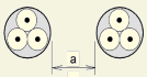
a Single-core cables
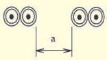
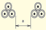
1 Values given apply to an installation depth of 0.7 m and a soil thermal resistivity of 2.5 K∙m/W. These are average values for the range of cable sizes and types in Tables B-2 to Table. The process of averaging together with rounding off can result in errors up to 10 percent in some cases. (Where more precise values are required, it may be calculated by methods given in IEC 60287-2-1.)
2 In case of a thermal resistivity lower than 2.5 K∙m/W the corrections factors can, in general, be increased and can be calculated by the methods given in IEC 60287-2-1.
3 If a circuit consists of m parallel conductors per phase, then for determining the reduction factor, this circuit should be considered as m circuits.
Table B-19 Reduction Factors for More than One Circuit, Cables Laid in Ducts in the Ground Installation Method D1 in Tables B-2 to B-5
A) Multi-core Cables in Single-way Ducts
| Number of Cables | Duct to Duct Clearance a | |||
| Nil(Ducts Touching) | 0.25 m | 0.5 m | 1.0 m | |
| (1) | (2) | (3) | (4) | (5) |
| 2 | 0.85 | 0.90 | 0.95 | 0.95 |
| 3 | 0.75 | 0.85 | 0.90 | 0.95 |
| 4 | 0.70 | 0.80 | 0.85 | 0.90 |
| 5 | 0.65 | 0.80 | 0.85 | 0.90 |
| 6 | 0.60 | 0.80 | 0.80 | 0.90 |
| 7 | 0.57 | 0.76 | 0.80 | 0.88 |
| 8 | 0.54 | 0.74 | 0.78 | 0.88 |
| 9 | 0.52 | 0.73 | 0.77 | 0.87 |
| 10 | 0.49 | 0.72 | 0.76 | 0.86 |
| 11 | 0.47 | 0.70 | 0.75 | 0.86 |
| 12 | 0.45 | 0.69 | 0.74 | 0.85 |
| 13 | 0.44 | 0.68 | 0.73 | 0.85 |
| 14 | 0.42 | 0.68 | 0.72 | 0.84 |
| 15 | 0.41 | 0.67 | 0.72 | 0.84 |
| 16 | 0.39 | 0.66 | 0.71 | 0.83 |
| 17 | 0.38 | 0.65 | 0.70 | 0.83 |
| 18 | 0.37 | 0.65 | 0.70 | 0.83 |
| 19 | 0.35 | 0.64 | 0.69 | 0.82 |
| 20 | 0.34 | 0.63 | 0.68 | 0.82 |
| B) Single-core Cables in Non-magnetic Single-way Ducts | ||||
| 2 | 0.80 | 0.90 | 0.90 | 0.95 |
| 3 | 0.70 | 0.80 | 0.85 | 0.90 |
| 4 | 0.65 | 0.75 | 0.80 | 0.90 |
| 5 | 0.60 | 0.70 | 0.80 | 0.90 |
| 6 | 0.60 | 0.70 | 0.80 | 0.90 |
| Number of Cables | Duct to Duct Clearance a | |||
| Nil(Ducts Touching) | 0.25 m | 0.5 m | 1.0 m | |
| (1) | (2) | (3) | (4) | (5) |
| 14 | 0.37 | 0.53 | 0.68 | 0.83 |
| 15 | 0.35 | 0.52 | 0.67 | 0.83 |
| 16 | 0.34 | 0.51 | 0.66 | 0.83 |
| 17 | 0.33 | 0.50 | 0.65 | 0.82 |
| 18 | 0.31 | 0.49 | 0.65 | 0.82 |
| 19 | 0.30 | 0.48 | 0.64 | 0.82 |
| 20 | 0.29 | 0.47 | 0.63 | 0.81 |
a Multi-core cables
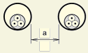
b Single-core cables
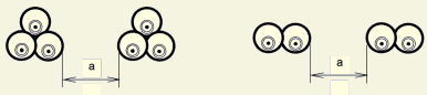
1 Values given apply to an installation depth of 0.7 m and a soil thermal resistivity of 2.5 K∙m/W. These are average values for the range of cable sizes and types in Tables B-2 to Table. The process of averaging together with rounding off can result in errors up to 10 percent in some cases. (Where more precise values are required, it may be calculated by methods given in IEC 60287-2-1.)
2 In case of a thermal resistivity lower than 2.5 K∙m/W, the corrections factors can, in general, be increased and can be calculated by the methods given in IEC 60287-2-1.
3 If a circuit consists of m parallel conductors per phase, then, for determining the reduction factor, this circuit should be considered as m circuits.
| Method of Installation in Table A-3 | Number of Trays or Ladders | Number of Cables per Tray or Ladder | |||||||
| 1 | 2 | 3 | 4 | 6 | 9 | ||||
| Perforated cable tray systems (see Note 3) | 31 | Touching | 1 | 1.00 | 0.88 | 0.82 | 0.79 | 0.76 | 0.73 |
| 2 | 1.00 | 0.87 | 0.80 | 0.77 | 0.73 | 0.68 | |||
| 3 | 1.00 | 0.86 | 0.79 | 0.76 | 0.71 | 0.66 | |||
| 6 | 1.00 | 0.84 | 0.77 | 0.73 | 0.68 | 0.64 | |||
| Spaced | 1 | 1.00 | 1.00 | 0.98 | 0.95 | 0.91 | - | ||
| 2 | 1.00 | 0.99 | 0.96 | 0.92 | 0.87 | - | |||
| 3 | 1.00 | 0.98 | 0.95 | 0.91 | 0.85 | - | |||
| Vertical perforated cable tray systems (see Note 4) | 31 | Touching | 1 | 1.00 | 0.88 | 0.82 | 0.78 | 0.73 | 0.72 |
| 2 | 1.00 | 0.88 | 0.81 | 0.76 | 0.71 | 0.70 | |||
| Spaced | 1 | 1.00 | 0.91 | 0.89 | 0.88 | 0.87 | - | ||
| 2 | 1.00 | 0.91 | 0.88 | 0.87 | 0.85 | - | |||
| Unperforated cable tray systems | 31 | Touching≥ 20 mm ≥ 300 mm | 1 | 0.97 | 0.84 | 0.78 | 0.75 | 0.71 | 0.68 |
| 2 | 0.97 | 0.83 | 0.76 | 0.72 | 0.68 | 0.63 | |||
| 3 | 0.97 | 0.82 | 0.75 | 0.71 | |||||
| Method of Installation in Table A-3 | Number of Trays or Ladders | Number of Cables per Tray or Ladder | |||||||
| 1 | 2 | 3 | 4 | 6 | 9 | ||||
| Spaced | 1 | 1.00 | 1.00 | 1.00 | 1.00 | 1.00 | - | ||
| 2 | 1.00 | 0.99 | 0.98 | 0.97 | 0.96 | - | |||
| 3 | 1.00 | 0.98 | 0.97 | 0.96 | 0.93 | - | |||
| NOTES1 Values given are averages for the cable types and range of conductor sizes considered in Tables A-8 to Table A-13. The spread of values is generally less than 5 percent.2 The factors apply to single layer groups of cables as shown above and do not apply when cables are installed in more than one layer touching each other. Values for such installations may be significantly lower and has to be determined by an appropriate method.3 Values are given for vertical spacing between cable trays of 300 mm and at least 20 mm between cable trays and wall. For closer spacing, the factors should be reduced.4 Values are given for horizontal spacing between cable trays of 225 mm with cable trays mounted back to back. For closer spacing, the factors should be reduced. | |||||||||
| Method of Installation in Table A-3 | Number of Trays or Ladders | Number of Three-Phase Circuits per Tray or Ladder | Use as a Multiplier to Current-carrying Capacity for | ||||
| 1 | 2 | 3 | |||||
| Perforated cable tray systems (see Note 3) | 31 | Touching | 1 | 0.98 | 0.91 | 0.87 | Three cables in horizontal formation |
| 2 | 0.96 | 0.87 | 0.81 | ||||
| 3 | 0.95 | 0.85 | 0.78 | ||||
| Vertical perforated cable tray systems (see Note 4) | 31 | Touching | 1 | 0.96 | 0.86 | - | Three cables in vertical formation |
| 2 | 0.95 | 0.84 | - | ||||
| Cable ladder systems, cleats, etc. (see Note 3) | 32 | Touching-T | 1 | 1.00 | 0.97 | 0.96 | Three cables in horizontal formation |
| 33 | 2 | 0.98 | 0.93 | 0.89 | |||
| 34 | 3 | 0.97 | 0.90 | 0.86 | |||
| Method of Installation in Table A-3 | Number of Trays or Ladders | Number of Three-Phase Circuits per Tray or Ladder | Use as a Multiplier to Current-carrying Capacity for | ||||
| 1 | 2 | 3 | |||||
| Perforated cable tray systems (see Note 3) | 31 | 1 | 1.00 | 0.98 | 0.96 | Three cables in trefoil formation | |
| 2 | 0.97 | 0.93 | 0.89 | ||||
| 3 | 0.96 | 0.92 | 0.86 | ||||
| Vertical perforated cable tray systems (see Note 4) | 31 | 1 | 1.00 | 0.91 | 0.89 | ||
| 2 | 1.00 | 0.90 | 0.86 | ||||
| Cable ladder systems, cleats, etc. (see Note 3) | 32 | 1 | 1.00 | 1.00 | 1.00 | ||
| 33 | 2 | 0.97 | 0.95 | 0.93 | |||
| 34 | 3 | 0.96 | 0.94 | 0.90 | |||
| NOTES1 Values given are averages for the cable types and range of conductor sizes considered in Table B-8 to Table B-13. The spread of values is generally less than 5 percent.2 The factors are given for single layers of cables (or trefoil groups) as shown in the table and do not apply when cables are installed in more than one layer touching each other. Values for such installations may be significantly lower and should be determined by an appropriate method.3 Values are given for vertical spacing between cable trays of 300 mm and at least 20 mm between cable trays and wall. For closer spacing, the factors should be reduced.4 Values are given for horizontal spacing between cable trays of 225 mm with cable trays mounted back to back. For closer spacing, the factors should be reduced.5 For circuits having more than one cable in parallel per phase, each set of conductors per three phase should be considered as a circuit for the purpose of this table.6 If a circuit consists of m parallel conductors per phase, then, for determining the reduction factor this circuit should be considered as m circuits. | |||||||
| Table C-1 Current-carrying Capacity in AmperesNOTE — For more information, refer Annex T of IS 732 : 2019. | ||||||||||||
| Reference Methods in Table B-1 | Number of Loaded Conductors and Type of Insulation | |||||||||||
| A1 | 3 PVC | 2 PVC | 3 XLPE | 2 XLPE | ||||||||
| A2 | 3 PVC | 2 PVC | 3 XLPE | 2 XLPE | ||||||||
| B1 | 3 PVC | 2 PVC | 3 XLPE | 2 XLPE | ||||||||
| B2 | 3 PVC | 2 PVC | 3 XLPE | 2 XLPE | ||||||||
| C | 3 PVC | 2 PVC | 3 XLPE | 2 XLPE | ||||||||
| E | 3 PVC | 2 PVC | 3 XLPE | 2 XLPE | ||||||||
| F | 3 PVC | 2 PVC | 3 XLPE | 2 XLPE | ||||||||
| (1) | (2) | (3) | (4) | (5) | (6) | (7) | (8) | (9) | (10) | (11) | (12) | (13) |
| Size (mm2) Copper | ||||||||||||
| 1.5 | 13 | 13.5 | 14.5 | 15.5 | 17 | 18.5 | 19.5 | 22 | 23 | 24 | 26 | - |
| 2.5 | 17.5 | 18 | 19.5 | 21 | 23 | 25 | 27 | 30 | 31 | 33 | 36 | - |
| 4 | 23 | 24 | 26 | 28 | 31 | 34 | 36 | 40 | 42 | 45 | 49 | - |
| 6 | 29 | 31 | 34 | 36 | 40 | 43 | 46 | 51 | 54 | 58 | 63 | - |
| 10 | 39 | 42 | 46 | 50 | 54 | 60 | 63 | 70 | 75 | 80 | 86 | - |
| 16 | 52 | 56 | 61 | 68 | 73 | 80 | 85 | 94 | 100 | 107 | 115 | - |
| 25 | 68 | 73 | 80 | 89 | 95 | 101 | 110 | 119 | 127 | 135 | 149 | 161 |
| 35 | - | - | - | 110 | 117 | 126 | 137 | 147 | 158 | 169 | 185 | 200 |
| 50 | - | - | - | 134 | 141 | 153 | 167 | 179 | 192 | 207 | 225 | 242 |
| 70 | - | - | - | 171 | 179 | 196 | 213 | 229 | 246 | 268 | 289 | 310 |
| 95 | - | - | - | 207 | 216 | 238 | 258 | 278 | 298 | 328 | 352 | 377 |
| 120 | - | - | - | 239 | 249 | 276 | 299 | 322 | 346 | 382 | 410 | 437 |
| 150 | - | - | - | - | 285 | 318 | 344 | 371 | 395 | 441 | 473 | 504 |
| 185 | - | - | - | - | 324 | 362 | 392 | 424 | 450 | 506 | 542 | 575 |
| 240 | - | - | - | - | 380 | 424 | 461 | 500 | 538 | 599 | 641 | 679 |
| Aluminium | ||||||||||||
| 2.5 | 13.5 | 14 | 15 | 16.5 | 18.5 | 19.5 | 21 | 23 | 24 | 26 | 28 | - |
| 4 | 17.5 | 18.5 | 20 | 22 | 25 | 26 | 28 | 31 | 32 | 35 | 38 | - |
| 6 | 23 | 24 | 26 | 28 | 32 | 33 | 36 | 39 | 42 | 45 | 49 | - |
| 10 | 31 | 32 | 36 | 39 | 44 | 46 | 49 | 54 | 58 | 62 | 67 | - |
| 16 | 41 | 43 | 48 | 53 | 58 | 61 | 66 | 73 | 77 | 84 | 91 | - |
| 25 | 53 | 57 | 63 | 70 | 73 | 78 | 83 | 90 | 97 | 101 | 108 | 121 |
| 35 | - | - | - | 86 | 90 | 96 | 103 | 112 | 120 | 126 | 135 | 150 |
| 50 | - | - | - | 104 | 110 | 117 | 125 | 136 | 146 | 154 | 164 | 184 |
| 70 | - | - | - | 133 | 140 | 150 | 160 | 174 | 187 | 198 | 211 | 237 |
| 95 | - | - | - | 161 | 170 | 183 | 195 | 211 | 227 | 241 | 257 | 289 |
| 120 | - | - | - | 186 | 197 | 212 | 226 | 245 | 263 | 280 | 300 | 337 |
| 150 | - | - | - | - | 226 | 245 | 261 | 283 | 304 | 324 | 346 | 389 |
| 185 | - | - | - | - | 256 | 280 | 298 | 323 | 347 | 371 | 397 | 447 |
| 240 | - | - | - | - | 300 | 330 | 352 | 382 | 409 | 439 | 470 | 530 |
| NOTE — The appropriate table of current-carrying capacity given in Annex B should be consulted to determine the range of conductor sizes for which the above current-carrying capacities are applicable, for each installation method. | ||||||||||||
| Installation Method | Sizemm2 | Number of Loaded Conductors and Type of Insulation | |||
| 2 PVC | 3 PVC | 2 XLPE | 3 XLPE | ||
| D1/D2 | Copper1.52.54610162535507095120150185240300 | 222938476381104125148183216246278312361408 | 18243139526786103122151179203230258297336 | 263444567395121146173213252287324363419474 | 222937466179101122144178211240271304351396 |
| D1/D2 | Aluminium2.54610162535507095120150185240300 | 22293648628096113140166189213240277313 | 18.524304052668094117138157178200230260 | 263442567393112132163193220249279322364 | 22293647617894112138164186210236272308 |
NOTE — For more information, refer Annex T of IS 732 : 2019.
| Sl No.(1) | Arrangement(2) | Number of Circuits or Multi-core Cables | ||||||||
| (3) | ||||||||||
| 1 | 2 | 3 | 4 | 6 | 9 | 12 | 16 | 20 | ||
| 1 | Bunched in air, on a surface, embedded or enclosed | 1.00 | 0.80 | 0.70 | 0.65 | 0.55 | 0.50 | 0.45 | 0.40 | 0.40 |
| 2 | Single layer on walls, floors or on unperforated trays | 1.00 | 0.85 | 0.80 | 0.75 | 0.70 | 0.70 | - | - | - |
| 3 | Single layer fixed directly under a ceiling | 0.95 | 0.80 | 0.70 | 0.70 | 0.65 | 0.60 | - | - | - |
| 4 | Single layer on perforated horizontal trays or on vertical trays | 1.00 | 0.90 | 0.80 | 0.75 | 0.75 | 0.70 | - | - | - |
| 5 | Single layer on cable ladder supports or cleats, etc. | 1.00 | 0.85 | 0.80 | 0.80 | 0.80 | 0.80 | - | - | - |
Selection of Conduit Systems
Table D-1 Suggested Characteristics for Conduit
153
NOTE — For more information, refer Annex W of IS 732 : 2019.
| Situation | Resistance to Compression | Resistance to Impact | Minimum Operating Temperature | Maximum Operating Temperature | ||
| Outdoor installation | Exposed installation | 3 | 3 | 2 | 1 | |
| Indoors use | Exposed installation | 2 | 2 | 2 | 1 | |
| Under floor installations (floor screed) | 2 | 3 | 2 | 1 | ||
| Embedded | Concrete | 3 | 3 | 2 | 1 | |
| Hollow wall/on wood (inflammable material) | 2 | 2 | 2 | 1 | ||
| In masonry | ||||||
| Building voids | ||||||
| Ceiling voids | ||||||
| Overhead mounting | 4 | 3 | 3 | 1 | ||
| NOTES 1 These values are only a sample of the characteristics for conduit given in IS 14930 (Part 1 and 2). 2 According to resistance to flame propagation, conduit systems of orange colour are only permitted when embedded in concrete. 3 For other methods for installation all colours are permitted with the exception of yellow, orange or red. | ||||||
Table D-2 Dimensions of Rigid Steel Conduits
NOTE — For more information, refer 7.1 of IS 9537 (Part 2) : 1981.
| Sl No. | Nominal Size of Conduit mm | Outside Diameter mm | Maximum Wall Thickness mm | Internal Cross Sectional Area of Conduit mm<sup>2</sup> |
|---|---|---|---|---|
| (1) | (2) | (3) | (4) | (5) |
| i) | 16 | 16 | 1.8 | 121 |
| ii) | 20 | 20 | 1.8 | 211 |
| iii) | 25 | 25 | 1.8 | 360 |
| iv) | 32 | 32 | 1.8 | 633 |
| v) | 40 | 40 | 2.2 | 995 |
| vi) | 50 | 50 | 2.2 | 1633 |
| vii) | 63 | 63 | 2.2 | 2697 |
Table D-3 Dimensions of Non-metallic Conduits (PVC) (Clause 5.9.3.6)
NOTE — For more information, refer 7.1 of IS 9537 (Part 2) : 1981.
| Sl No. | Nominal Size mm | Outside Diameter mm | Light Min Inside Diameter mm | (LMS) Cross Sectional Areamm<sup>2</sup> | Medium Min Inside Diameter mm | (MMS) Cross Sectional Areamm<sup>2</sup> | Heavy Min Inside Diameter mm | (HMS) Cross Sectional Areamm<sup>2</sup> |
|---|---|---|---|---|---|---|---|---|
| (1) | (2) | (3) | (4) | (5) | (6) | (7) | (8) | (9) |
| i) | 16 | 16 | 13.7 | 147 | 13.0 | 133 | 12.2 | 117 |
| ii) | 20 | 20 | 17.4 | 238 | 16.9 | 224 | 15.8 | 196 |
| iii) | 25 | 25 | 22.1 | 384 | 21.4 | 360 | 20.6 | 333 |
| iv) | 32 | 32 | 28.6 | 642 | 27.8 | 607 | 26.6 | 556 |
| v) | 40 | 40 | 35.8 | 1007 | 35.4 | 984 | 34.4 | 929 |
| vi) | 50 | 50 | 45.1 | 1598 | 44.3 | 1541 | 43.2 | 1466 |
| vii) | 63 | 63 | 57.0 | 2552 |
Table D-4 Dimensions of Single Core Non-Sheathed Cables with Rigid Conductor Class 1 or Class 2 NOTES
1 For more information, refer 16.1.2 and 16.1.3 of IS 694 : 2010.
2 Class 1 is solid conductor and class 2 is stranded conductor, for further details, refer Table 3 of IS 694.
| Sl No. | Nominal Cross Sectional Area of Conductormm<sup>2</sup> | Class of Conductor | Thickness of Insulation mm | Maximum Overall Diameter mm | Crosssectional Area of Cable mm<sup>2</sup> |
|---|---|---|---|---|---|
| (1) | (2) | (3) | (4) | (5) | (6) |
| i) | 0.5 | 1 | 0.6 | 2.3 | 4.15 |
| ii) | 0.75 | 1 | 0.6 | 2.5 | 4.91 |
| iii) | 1 | 1 | 0.6 | 2.7 | 5.73 |
| iv) | 1.5 | 1 | 0.7 | 3.2 | 8.04 |
| v) | 1.5 | 2 | 0.7 | 3.3 | 8.55 |
| vi) | 2.5 | 1 | 0.8 | 3.9 | 11.95 |
| vii) | 2.5 | 2 | 0.8 | 4 | 12.57 |
| viii) | 4 | 1 | 0.8 | 4.4 | 15.21 |
| ix) | 4 | 2 | 0.8 | 4.6 | 16.62 |
| x) | 6 | 1 | 0.8 | 5 | 19.64 |
| xi) | 6 | 2 | 0.8 | 5.2 | 21.24 |
| xii) | 10 | 1 | 1 | 6.4 | 32.17 |
| xiii) | 10 | 2 | 1 | 6.7 | 35.26 |
| xiv) | 16 | 2 | 1 | 7.8 | 47.78 |
| xv) | 25 | 2 | 1.2 | 9.7 | 73.90 |
| Sl No. | Nominal Size of Conduit mm | Maximum Distance Between Supports | |||||
| Rigid Metal | Rigid Insulation | Pliable | |||||
| Horizontal m | Vertical m | Horizontal m | Vertical m | Horizontal m | Vertical m | ||
| (1) | (2) | (3) | (4) | (5) | (6) | (7) | (8) |
| i) | Not exceeding 16 | 0.75 | 1.0 | 0.75 | 1.0 | 0.3 | 0.5 |
| ii) | Exceeding 16 and not 25 | 1.75 | 2.0 | 1.5 | 1.75 | 0.4 | 0.6 |
| iii) | Exceeding 25 and not exceeding 40 | 2.0 | 2.25 | 1.75 | 2.0 | 0.6 | 0.8 |
| iv) | Exceeding 40 | 2.25 | 2.5 | 2.0 | 2.0 | 0.8 | 1.0 |
| NOTE — A flexible conduit is not normally required to be supported in its run. | |||||||
| Designation of Conductors | Identification by Colour | |
| Supply a.c. system 3 phase | Phase 1 | Red |
| Phase 2 | Yellow | |
| Phase 3 | Blue | |
| Neutral | Black | |
| Apparatus a.c. system | Phase 1 | Red |
| Phase 2 | Yellow | |
| Phase 3 | Blue | |
| d.c. system | Positive | Red |
| Negative | Blue | |
| Mid-wire | Black | |
| Supply a.c.1) system 1 phase | Phase | Red |
| Neutral | Black | |
| Protective Conductor | - | Green Yellow |
| Functional earth conductor | - | cream |
| 1) For single phase a.c. systems, the red and black coloured cables are recommended if the circuit is in isolation. In case single phase conductors, associated with the 3-phase system, the phase conductor shall use the same colour as that phase from which it is derived. | ||
| Sl No. | No. of Cores | Cables for Fixed Wiring and Cords | Flexible Cables |
|---|---|---|---|
| (1) | (2) | (3) | (4) |
| i) | 1 | Red/black/yellow/blue/white/grey | Red/black/yellow/blue/white/grey |
| ii) | 2 | Red, -black | Red, black |
| iii) | 3 | Red, yellow, blue | Red, black, yellow-green or red, yellow, blue |
| iv) | 4 | Red, yellow, blue, black | Red, yellow, blue, yellow-green or red, yellow, blue, black |
| v) | 5 | Red, yellow, blue, black and grey or yellow, blue, green, white and yellow-green |
NOTES
1 For more information, refer Table 2 of IS 694 : 2010.
2 For further details and for cores 6 to 25, refer Table 2 of IS 694 : 2010.
ANNEX F
(Clause 6.5.1)
| Sl No. | Purpose of Final Circuit Fed from Conductors or Switchgear to which Diversity Applies | Individual House- Hold Installations, Including Individual Dwelling of a Block | Type of PremisesSmall Shops, Stores Offices and Business Premises | Small Hotels, Boarding Houses etc. |
| (1) | (2) | (3) | (4) | (5) |
| i) | Lighting | 66 Percent of total current demand | 90 Percent of total current demand | 75 Percent of total current demand |
| ii) | Heating and power | 100 Percent of total current demand up to 10A+ 50 Percent of any current demand in excess of 10A | 100 Percent of full load of largest appliance+75 Percent of remaining appliances | 100 Percent of full load of largest appliance+80 Percent of second largest appliance+60 Percent of remaining appliances |
| iii) | Cooking appliances | 16A | 100 Percent of full load of largest appliance | 100 Percent of full load of largest appliance |
| + 30 Percent of full load of connected cooking appliances in excess of 16A | +80 Percent of full load of second largest appliance | +80 Percent of full load of second largest appliance | ||
| + 6A if outlet socket is incorporated in unit | +60 Percent of full load of remaining appliances | +60 Percent of full load of remaining appliances | ||
| iv) | Motors other than lift motors which are subject to special considerations | — | 100 Percent of full load of largest motor+80 Percent of full load of second largest motor+60 Percent of full load of remaining motors | 100 Percent of full load of largest motor+50 Percent of full load of remaining motors |
| v) | Water heater instantaneous type 1) | 100 Percent of full load of largest appliance+100 Percent of full load of second largest appliance | 100 Percent of full load of largest appliance+100 Percent of full load of second largest appliance | 100 Percent of full load of largest appliance+100 Percent of full load of second largest appliance |
| +25 Percent of full load of remaining appliances | +25 Percent of full load of remaining appliances | +25 Percent of full load of remaining appliances | ||
| vi) | Water heater thermostatically controlled | No diversity allowable 2) | — | — |
1) For the purpose of the table, an instantaneous water heater is deemed to heat water only when the tap is turned on and therefore, uses electricity intermittently.
2) It is important to ensure that the distribution boards are of sufficient rating to take the total load connected to them without the application of any diversity.
NOTE — For more information, refer Annex HH of IS 732 : 2019.
| Examples of Applications | Requirements | ||||||||
| 1 | 2 | 3 | 4 | 5 | 6 | 7 | 8 | 9 | |
| Extended Duration or Remote Controlled Circuit | Escape Sign Luminaires in Maintained Mode | Central Power Supply System | Low Power Supply System | Self-contained Battery Unit | Motor-Generator Unit with no Break (0 s) | Motor-Generator Unit with Short Break (< 0.5 s) | Motor-Generator Unit with Medium Break (< 15 s) | Dual Supply System | |
| Assembly halls, assembly rooms | ** | ✓ | ✓ | ✓ | ✓ | ✓ | ✓ | ✓ | ✓ |
| Exhibition halls | ** | ✓ | ✓ | ✓ | ✓ | ✓ | ✓ | ✓ | ✓ |
| Theatres, cinemas | ** | ✓ | ✓ | ✓ | ✓ | ✓ | ✓ | ✓ | ✓ |
| Sports arenas | ** | ✓ | ✓ | ✓ | ✓ | ✓ | ✓ | ✓ | ✓ |
| Sales areas | ** | ✓ | ✓ | ✓ | ✓ | ✓ | ✓ | ✓ | ✓ |
| Restaurants | ** | ✓ | ✓ | ✓ | ✓ | ✓ | ✓ | ✓ | ✓ |
| Hospitals, treatment centres | ** | ✓ | ✓ | ✓ | ✓ | ✓ | ✓ | ✓ | ✓ |
| Hotels, guest houses * | ** | ✓ | ✓ | ✓ | ✓ | ✓ | ✓ | ✓ | ✓ |
| Residential care homes * | ** | ✓ | ✓ | ✓ | ✓ | ✓ | ✓ | ✓ | ✓ |
| High-rise buildings * | ** | ✓ | ✓ | ✓ | ✓ | ✓ | ✓ | ✓ | ✓ |
| Schools | ** | ✓ | ✓ | ✓ | ✓ | ✓ | ✓ | ✓ | ✓ |
| Enclosed car parks | ✓ | ✓ | ✓ | ✓ | ✓ | ✓ | ✓ | ✓ | |
| Escape routes in workplaces | ✓ | ✓ | ✓ | ✓ | ✓ | ✓ | ✓ | ✓ | |
| High risk task areas | ✓ | ✓ | ✓ | ✓ | ✓ | ✓ | ✓ | ✓ | |
| Stages | ** | ✓ | ✓ | ✓ | ✓ | ✓ | ✓ | ✓ | ✓ |
| ✓ denotes suitable systems.* Premises (for example, guest houses, hotels, residential care homes and high-rise buildings) requiring all day operations, the rated operating time for the emergency lighting should be 8 h or shall be operatable with illuminated push buttons for a fixed time by the occupants. In this case, the push buttons and the timing equipments should also run on the emergency mode supply.** Denotes applications which require either extended duration or a circuit like the remote-controlled circuit to ensure protection for longer than 60 min. | |||||||||
Table I.1 Optimum Size/Number of Fans for Rooms of Different Sizes NOTE — For more details, refer Table 13 and 5.7.4 of Part 8/Sec 1 of NBC 2016.
| Sl | Room | O | ptimum Si | ze (mm/Nu | mber of F | ans for Ro | om Length | ) | ||||
|---|---|---|---|---|---|---|---|---|---|---|---|---|
| No. | wi mdth | 4 m | 5 m | 6 m | 7 m | 8 m | 9 m | 10 m | 11 m | 12 m | 14 m | 16 m |
| (1) | (2) | (3) | (4) | (5) | (6) | (7) | (8) | (9) | (10) | (11) | (12) | (13) |
| i) | 3 | 1 200/1 | 1 400/1 | 1 500/1 | 1050/2 | 1 200/2 | 1 400/2 | 1 400/2 | 1 400/2 | 1 200/3 | 1 400/3 | 1 400/3 |
| ii) | 4 | 1 200/1 | 1 400/1 | 1 200/2 | 1 200/2 | 1 200/2 | 1 400/2 | 1 400/2 | 1 500/2 | 1 200/3 | 1 400/3 | 1 500/3 |
| iii) | 5 | 1 400/1 | 1 400/1 | 1 400/2 | 1 400/2 | 1 400/2 | 1 400/2 | 1 400/2 | 1 500/2 | 1 400/3 | 1 400/3 | 1 500/3 |
| iv) | 6 | 1 200/2 | 1 400/2 | 900/4 | 1050/4 | 1 200/4 | 1 400/4 | 1 400/4 | 1 500/4 | 1 200/6 | 1 400/6 | 1 500/6 |
| v) | 7 | 1 200/2 | 1 400/2 | 1050/4 | 1050/4 | 1 200/4 | 1 400/4 | 1 400/4 | 1 500/4 | 1 200/6 | 1 400/6 | 1 500/6 |
| vi) | 8 | 1 200/2 | 1 400/2 | 1 200/4 | 1 200/4 | 1 200/4 | 1 400/4 | 1 400/4 | 1 500/4 | 1 200/6 | 1 400/6 | 1 500/6 |
| vii) | 9 | 1 400/2 | 1 400/2 | 1 400/4 | 1 400/4 | 1 400/4 | 1 400/4 | 1 400/4 | 1 500/4 | 1 400/6 | 1 400/6 | 1 500/6 |
| viii) | 10 | 1 400/2 | 1 400/2 | 1 400/4 | 1 400/4 | 1 400/4 | 1 400/4 | 1 400/4 | 1 500/4 | 1 400/6 | 1 400/6 | 1 500/6 |
| ix) | 11 | 1 500/2 | 1 500/2 | 1 500/4 | 1 500/4 | 1 500/4 | 1 500/4 | 1 500/4 | 1 500/4 | 1 500/6 | 1 500/6 | 1 500/6 |
| x) | 12 | 1 200/3 | 1 400/3 | 1 200/6 | 1 200/6 | 1 200/6 | 1 400/6 | 1 400/6 | 1 500/6 | 1 200/7 | 1 400/9 | 1 400/9 |
| xi) | 13 | 1 400/3 | 1 400/3 | 1 200/6 | 1 200/6 | 1 200/6 | 1 400/6 | 1 400/6 | 1 500/6 | 1 400/9 | 1 400/9 | 1 500/9 |
| xii) | 14 | 1 400/3 | 1 400/3 | 1 400/6 | 1 400/6 | 1 400/6 | 1 400/6 | 1 400/6 | 1 500/6 | 1 400/9 | 1 400/9 | 1 500/9 |
SP 30 : 2023
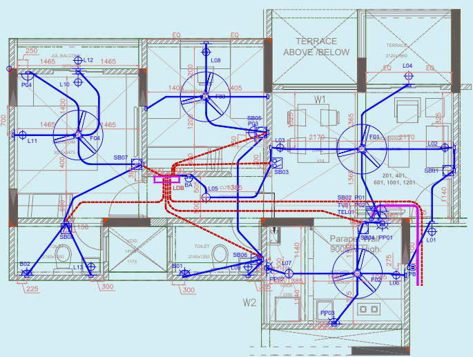
| 1200MM CEILING FAN | |
|---|---|
| CEILING LIGHT POINT. | |
| WALL LIGHT POINT | |
| SWITCH BOARD WITH LIGHT SWITCHES | |
| SWITCH BOARD WITH LIGHT SWITCHES FAN REGULATOR | |
| SWITCH BOARD WITH LIGHT & BOILER SWITCHES | |
| 5A SOCKET WITH SWITCH. | |
| 5A/15A SOCKET WITH SWITCH | |
| T.V. ANTENNA SOCKET OUTLET | |
| SINGLE TELEPHONE SOCKET OUTLET | |
| BELL PUSH | |
| BUZZER | |
| 20A SOCKET ONLY FOR BOILER | |
| DISTRIBUTION BOARD (DB) | |
| ∅25 mm FRPVC 2mm THICK CONDUIT FOR TEL/DATA WIRING | |
| ∅25mm FRPVC 2mm THICK CONDUIT FOR MAINS/SUBMAINS | |
| ∅25mm FRPVC 2mm THICK CONDUIT FOR POINT WIRING | |
| CEILING LIGHT POINT ON TIMER 2. |
| SWITCH BOARD SCHEDULE 2 BHK EVEN FLOOR FTALS | SWITCH BOARD SCHEDULE 2 BHK EVEN FLOOR FTALS | SWITCH BOARD SCHEDULE 2 BHK EVEN FLOOR FTALS | SWITCH BOARD SCHEDULE 2 BHK EVEN FLOOR FTALS | SWITCH BOARD SCHEDULE 2 BHK EVEN FLOOR FTALS | SWITCH BOARD SCHEDULE 2 BHK EVEN FLOOR FTALS | SWITCH BOARD SCHEDULE 2 BHK EVEN FLOOR FTALS | SWITCH BOARD SCHEDULE 2 BHK EVEN FLOOR FTALS |
| ROOM NAME | SWITCH BOARD | HEIGHT FROM FFL in mm | POINT | COMMENTS | MODULE | REQUIRED MODULES | STANDARD MODULES |
| ENTRANCE LOBBY | 1 250 | PB | 1 NO. OF 5A SWITCH FOR BELL PUSH | 1 | 1 | 1 | |
| LIVING/DINING ROOM+ LOBBY | SB0 1 | 1 250 | PB | 1 NO. OF 5A SWITCH FOR CONTROL FOR BELL PUSH | 1 | 6 | 6 |
| LIVING/DINING ROOM+ LOBBY | SB0 1 | 1 250 | L0 1 | 1 NO. OF 5A LIGHT SWITCH FOR WALL LIGHT POINT | 1 | 6 | 6 |
| LIVING/DINING ROOM+ LOBBY | SB0 1 | 1 250 | L02 | 1 NO. OF 5A LIGHT SWITCH FOR WALL LIGHT POINT | 1 | 6 | 6 |
| LIVING/DINING ROOM+ LOBBY | SB0 1 | 1 250 | F0 1 | 1 NO. OF 5A SWITCH WITH FAN REGULATOR | 3 | 6 | 6 |
| LIVING/DINING ROOM+ LOBBY | SB02 | 900 | TV0 1 TEL 1 P0 1 PO2 | 1 NO. SOCKET FOR TV | 1 | 8 | 8 |
| LIVING/DINING ROOM+ LOBBY | SB02 | 900 | TV0 1 TEL 1 P0 1 PO2 | 1 NO. SOCKET FOR TELEPHONE | 1 | 8 | 8 |
| LIVING/DINING ROOM+ LOBBY | SB02 | 900 | TV0 1 TEL 1 P0 1 PO2 | 1 NO. OF 5A SOCKET & SWITCH ON BOARD | 3 | 8 | 8 |
| LIVING/DINING ROOM+ LOBBY | SB02 | 900 | TV0 1 TEL 1 P0 1 PO2 | 1 NO. OF 5A SOCKET & SWITCH ON BOARD | 3 | 8 | 8 |
| LIVING/DINING ROOM+ LOBBY | SB03 | 1 250 | L03 | 1 NO. OF 5A LIGHT SWITCH FOR WALL LIGHT POINT | 1 | 3 | 3 |
| LIVING/DINING ROOM+ LOBBY | SB03 | 1 250 | L04 | 1 NO. OF 5A LIGHT SWITCH FOR WALL LIGHT POINT | 1 | 3 | 3 |
| LIVING/DINING ROOM+ LOBBY | SB03 | 1 250 | L05 | 1 NO. OF 5A LIGHT SWITCH FOR WALL LIGHT POINT | 1 | 3 | 3 |
| KITCHEN + DRY BALCONY | SB04 | 1 250 | F02 | 1 NO. OF 5A SWITCH FOR FAN REGULATOR | 3 | 5 | 6 |
| KITCHEN + DRY BALCONY | 1 250 | L06 | 1 NO. OF 5A LIGHT SWITCH FOR WALL LIGHT POINT | 1 | 5 | 6 | |
| KITCHEN + DRY BALCONY | L07 | 1 NO. OF 5A LIGHT SWITCH FOR WALL LIGHT POINT | 1 | 5 | 6 | ||
| KITCHEN + DRY BALCONY | 1 250 | PP0 1 | 1 NO. OF 5/1 5A SOCKET & SWITCH FOR REFRIGERATOR | 3 | 3 | 3 | |
| KITCHEN + DRY BALCONY | 1 200 | PP02 | 1 NO. OF 5/1 5A SOCKET & SWITCH FOR AQUAGUARD | 3 | 3 | 3 | |
| KITCHEN + DRY BALCONY | 1 250 | PP03 | 1 NO. OF 5/1 5A SOCKET & SWITCH FOR WASHING M/C | 3 | 3 | 3 | |
| BEDROOM - 1 | SB05 | 1 250 | L08 | 1 NO. OF 5A LIGHT SWITCH FOR WALL LIGHT POINT | 1 | 7 | 7 |
| BEDROOM - 1 | SB05 | 1 250 | P03 | 1 NO. OF 5A SOCKET & SWITCH ON BOARD | 3 | 7 | 7 |
| BEDROOM - 1 | SB05 | 1 250 | F03 | 1 NO. OF 5A SWITCH WITH FAN REGULATOR | 3 | 7 | 7 |
| TOILET - 1 | SB06 | 1 350 | L09 | 1 NO. OF 5A LIGHT SWITCH FOR WALL LIGHT POINT | 1 | 2 | 2 |
| TOILET - 1 | SB06 | 1 350 | B0 1 | 1 NO. OF 20A SWITCH FOR GEYSER WITH INDICATOR | 1 | 2 | 2 |
| TOILET - 1 | 2 1 00 | B0 1 | 1 NO. OF 20 A SOCKET OUTLET FOR GEYSER | 2 | 2 | 2 | |
| BEDROOM -2 | SB07 | 1 250 | L 1 0 | 1 NO. OF 5A LIGHT SWITCH FOR WALL LIGHT POINT | 1 | 6 | 6 |
| BEDROOM -2 | SB07 | 1 250 | L 1 1 | 1 NO. OF 5A LIGHT SWITCH FOR WALL LIGHT POINT | 1 | 6 | 6 |
| BEDROOM -2 | SB07 | 1 250 | L 1 2 | 1 NO. OF 5A LIGHT SWITCH FOR WALL LIGHT POINT | 1 | 6 | 6 |
| BEDROOM -2 | SB07 | 1 250 | F03 | 1 NO. OF 5A SWITCH WITH FAN REGULATOR | 3 | 6 | 6 |
| BEDROOM -2 | 600 | P04 | 1 NO OF 5A SOCKET & SWITCH INDEPENDANT | 3 | |||
| TOILET 2 | SB08 | 1 250 | L 1 2 | 1 NO. OF 5A LIGHT SWITCH FOR WALL LIGHT POINT | 1 | 2 | 2 |
| TOILET 2 | SB08 | 1 250 | B0 1 | 1 NO. OF 20A SWITCH FOR GEYSER WITH INDICATOR | 1 | 2 | 2 |
| TOILET 2 | 2 1 00 | B0 1 | 1 NO OF 20A SOCKET OUTLET FOR GEYSER | 2 | 2 | 2 | |
| PASSAGE | ON BEAM | BA | BELL ANNOUNCER | - | |||
| PASSAGE | 2 1 00 | DB | DISTRIBUTION BOARD | - |
| IS/Other Publications | Title |
|---|---|
| 371 : 1999 | Ceiling roses |
| 374 : 2019 | Electrical ceiling fans and regulators |
| 694 : 2010 | PVC insulated unsheathed and sheathed cables/cords with rigid and flexible conductors |
| 732 : 2019 | Code of practice for wiring installations |
| 1255 : 1983 | Code of practice for installation and maintenance of cables up to and including 33kV rating |
| 1258 : 2005 | Bayonet lamp holders |
| 1293 : 2019 | Plugs and socket-outlets of rated voltage upto and including 250 volts and ratted current upto and 16 amperes — Specification (fourth revisions) |
| 2032 : 1987 | Graphical symbols in the field of electro-technology |
| 3854 : 1997 | Switches for domestic and similar purposes |
| 9537 (Part 1) : 1980 | Conduits for electrical installations: Part 1 General |
| 9537 (Part 2) : 1981 | Conduits for electrical installations: Part 2 Rigid steel |
| 9537 (Part 3) : 1983 | Conduits for electrical installations: Part 3 Insulating material |
| 9537 (Part 4) : 1983 | Conduits for electrical installations: Part 4 Pliable self-recovering |
| 9537 (Part 5) : 2000 | Conduits for electrical installations: Part 5 Pliable insulating material |
| 9537 (Part 6) : 2000 | Conduits for electrical installations: Part 6 Pliable metal |
| 10322 (Part 1) : 2014 | Luminaires: Part 1 General Requirements |
| 12360 : 1988 | Voltage bands for electrical installations |
| 12640 (Part 1) : 2016 | Residual current operated circuit breakers for household and similar purposes |
| 12640 (Part 2) : 2018 | Residual current operated circuit breakers with integral over current protection (RCBOs) |
| 13032 : 1991 | AC MCB Boards for voltage not exceeding 1 000 V |
| 13703 : 1993 | Low voltage fuses for voltage not exceeding 1 000 V a..c. or 1500 V d.c. |
| 14772 : 2000 | Enclosures for accessories for household and similar fixed electrical installations |
| 14927 (Part 1) : 2001 | Cable trunking systems and cable ducting systems for electrical Installation: Part 1 General requirements |
| 14927 (Part 2) : 2001 | Cable trunking systems and cable ducting systems for electrical Installation: Part 2 Intended for mounting on walls or ceilings |
| 16205(Part 1) : 2017 | Conduit systems for cable management — General requirements |
| 16205 (Part 21) : 2017 | Conduit systems for cable management — Particular requirements — Rigid conduit systems |
| 16205 (Part 22) : 2017 | Conduit systems for cable management — Particular requirements — Pliable conduit systems |
| 16205 (Part 23) : 2017 | Conduit systems for cable management — Particular requirements — Flexible conduit systems |
| 16205 (Part 24) : 2017 | Conduit systems for cable management — Particular requirements — Conduit systems buried under ground |
| IEC 60061-2 : 1969 | Lamp caps and holders together with gauges for the control of interchangeability and safety — Part 2 Lampholders |
| IS/Other Publications | Title |
|---|---|
| IEC 60364-5-52 : 2009-10 | Low voltage electrical installations — Selection and erection of electrical equipment — Wiring systems |
| IEC 60670 | Boxes and enclosures for electrical accessories for household and similar fixed electrical installations |
| IEC 61008-1 : 2010 | Residual current operated circuit breakers without integral over current protection — Part 1 General rules |
| IEC 61084 : 2017 | Cable trunking systems and cable ducting systems for electrical installation |
| IEC 61439-1 : 2020 | Low voltage switchgears and control gear assemblies — General rules |
| IEC 61439-6 : 2012 | Low voltage switchgears and control gear assemblies — Busbar trunking systems |
| IEC 61534-1 : 2011 | Power-track systems — Part 1 General requirements |
| IEC 61534-21 : 2021 | Power-track systems — Part 21 For wall and ceiling mounting |
| IEC 61534-22 : 2021 | Power-track systems —Part 22 On floor and under floor mounting |
| IEC 61537 : 2006 | Cable management — Cable trey system and cable ladder systems |
| NBC 2016 | National Building Code |
SP 30 : 2023
Electrical shock is a physiological reaction caused by electric current passing through the human body. Usually electrical shock occurs when body part comes in contact with a live conductor. The severity of the shock depends on the magnitude of the current, the parts of the body through the current flows and the duration of the current flow.
A current of greater than 40 mA for more than 3 s passing through a human being is fatal, unless interrupted iin a relatively short time. The four zones of current-magnitude/time- duration, giving the path physiological effects of the electric shock are described in IS/IEC 60479-1 : 2005 and are given in Annex A.
This section of the code (Part 1/Sec 10) deals with protection against electric shock as applied to electrical installations. It is based on 4.2 of IS 732, which is a basic safety standard that applies to the protection of persons and livestock. The fundamental rule of protection against electric shock, is that hazardous live parts shall not be accessible and accessible conductive parts shall not be hazardous live, neither under normal conditions nor under single fault conditions. The protection under normal conditions is provided by basic protective provisions and protection under single fault conditions is provided by fault protective provisions.
IS/IEC Number
Title
12640 (Part 1/Sec 2)
IS/IEC 60479-1 : 2018
IEC 60755
Residual current operated circuit breakers for household and similar use Effects of current on human beings and livestock: Part 1 General aspects General safety requirements for residual current operated protective devices
3.1 Direct Contact — When a person comes in contact with a live conductor, it is called electric shock by direct contact.

Fig. 1A Direct Contact
3.2 Indirect Contact — When a person comes in contact with an exposed conductive-part, which is normally not live but has become live mainly due to insulation failure, is called electric shock by indirect contact.

Fig. 1B Indirect Contact
Three steps towards protection against electric shock are briefly described below. For details, please refer 4.2 of IS 732:
4.1.1 Basic protection is provided by basic insulation of live parts or by barriers or enclosures.
4.1.2 According to IS 732 (see 4.2.11.3.3 of IS 732), additional protection by means of 30 mA RCD shall be provided for circuits supplying socket-outlets with a rated current of 20 A at all locations, and for circuits supplying mobile equipment with a rated current 32 A for outdoor use.
Fault protection is provided by protective equipotential bonding and automatic disconnection in case of occurrence of a fault. Exposed-conductive-parts of an electrical equipment are separated from the live parts of the equipment by the “basic insulation”. Failure of the basic insulation can result in the exposed-conductive-parts being alive. Coming in contact with electrical equipment which is dead under normal conditions but is alive due to insulation failure is referred to as an indirect contact.
In all parts of an installation, one or more protective measures shall be applied, considering the conditions of external influence. The following protective measures are generally permitted:
a) automatic disconnection of supply;
b) double or reinforced insulation;
c) electrical separation for the supply of one item of current-using equipment; and
d) extra-low-voltage (SELV and PELV).
First step: The earthing of all exposed-conductive-parts of electrical equipment in the installation shall be connected with an equipotential bonding network.
Second step: Automatic disconnection of the supply of the section of the installation concerned, in such a way that the touch-voltage/time safety requirements are respected for any level of touch voltage.
As per IS 732, all circuits shall be provided with an overcurrent protection device. If the earth fault loop impedance is low enough to cause these devices to operate within the specified times, (that is, sufficient current can flow to earth under fault conditions), such devices may be relied upon to give the requisite automatic disconnection of supply. If the earth fault loop impedance does not permit the overcurrent protective devices to give automatic disconnection of the supply under earth fault conditions, measures shall be taken to reduce the impedance. It may be achieved by using protective multiple earthing or by additional earth electrodes. However, there are practical limitations to both approaches.
In case of impedance/arcing faults, series protective devices may be ineffective to clear the faults. Automatic disconnection of supply shall be provided by residual current devices, with a sensitivity adapted to the earth loop impedance (for example, 300 mA or 500 mA RCDs).
Also, a.c. circuit may be provided with additional protection using 30 mA RCD.
For TT and TN earthing system, Table 1 of IS 732 specifies tripping time for each system for safe protection.
a) Double or reinforced insulation
Requirements for Double or reinforced Insulation shall be in accordance with 4.2.12 of IS 732.
b) Electrical separation for the supply of one item of current-using equipment
In a.c. system, additional protection by means of a 30 mA residual protective device (RCD) in accordance with 4.2.15.1 of IS 732 shall be provided for:
a) At the incomer of every sub-distribution board with one or more outgoing circuits with fixed installation and socket-outlets for safety of users from earth leakage.
b) Mobile equipment.
System voltage independent RCD not exceeding 30 mA shall be used for domestic and similar application.
IEC 60755 defines four types of RCDs, for a.c. applications, aiming at covering the various types of residual current waveshape. These types are known as type AC, type A, type F and type B. All these devices are intended to be used on a.c. supply systems.
NOTE — IEC/TS 63053 is published for DC-RCD.
In most cases, the expected fault current is of the same frequency and waveshape as that of supply (sinusoidal 50 Hz), either because the fault may occur only on the supply conductors (for example, if the appliance itself is of class 2), or because the load is resistive.
Residual current devices intended to detect sinusoidal residual currents are defined by IEC 60755 as type AC, and are marked with a following standard symbol.

“An RCD for which tripping is ensured for residual sinusoidal alternating currents, whether suddenly applied or slowly rising. ”
RCDs of type AC are used for general purposes applications.
The expected fault current may contain pulsating DC waveshape (for example, the fault current flowing through a rectifier, as shown in Fig. 2). This is the case where the RCD supplies a load containing rectifiers, and occurrence of fault could create such residual current. The waveshape of the fault current is, then, defined as pulsating DC residual current. Residual current devices able to detect such waveshape are known as type A RCD.
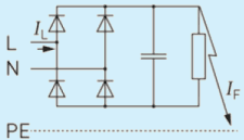
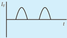
Fig. 2 Example of Application Which May Create Type a Fault Current And Corresponding Waveshape (I )
In addition, such devices are able to “withstand” smooth DC residual current of 6 mA superimposed on the residual current. It is important to note that an RCD of type A is able to detect pulsating DC residual current and in addition sinusoidal residual current.
Residual current devices of type A are defined in IEC 60755 and are marked with the following standard symbol.

RCD of type A shall be used where the application may create pulsating DC residual current. For example single phase Class 1 devices with rectifying circuit like cooking plates.
The expected fault current may contain composite residual currents, with frequencies ranging from a few hertz up to 1 000 Hz, as shown in Fig. 3. This is the case where the RCD supplies a load with single phase motor drive. The waveshape of the fault current is then defined as composite residual current. Residual current devices able to detect such waveshape are known as type F RCD.
Such devices are also able to withstand smooth DC residual current of 10 mA superimposed on the residual current. In addition an RCD of type F is also able to detect all the residual currents detected by a type A RCD. Therefore, a type F RCD can also be used when a type A RCD (or type AC RCD) is required by installation standards.
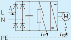
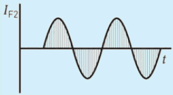
Fig. 3 Example of Application Which May Create Type F Fault Current and Corresponding Waveshape (I )
Residual current devices of type F are defined in IEC 60755 and are marked with one of the following standard symbol, showing that an RCD of type F complies also with the requirements for type A.

RCDs of type F shall be used in the cases where the application may create composite residual current. For example single phase Class 1 devices containing a motor controlled by a variable speed drive. This is the case of heat pump or air conditioner.
The waveshape of the residual current may contain various other components, such as frequencies higher than 50 Hz or 60 Hz, non-sinusoidal waveshape, waveshape resulting from rectifying circuits with six diodes bridge, or even smooth DC, as shown in Fig. 4. This is the case when the RCD supplies, for example, a motor with three phase speed-drive. Residual current devices able to detect such waveshape are known as type B RCD.
Such devices are also able to withstand smooth DC residual current of 10 mA superimposed on the residual current. In addition an RCD of type B is also able to detect all the residual currents detected by a type F RCD. Therefore, a type B RCD can be used when a type F RCD (or type A or type AC RCD) is required by installation standards.
SP 30 : 2023
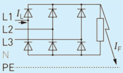
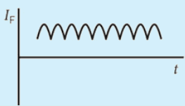
Fig. 4 Example of Application Which May Create Type B Fault Current and Corresponding Waveshape (I )
Residual current devices of type B are defined in IEC 60755.
An RCD for which tripping is ensured as for type F and, in addition:
a) for residual sinusoidal alternating currents up to 1 000 Hz;
b) for residual alternating currents superimposed on a smooth direct current of 0.4 times the rated residual current ( I Δ n ) or 10 mA whichever is the highest value;
c) for residual pulsating direct currents superimposed on a smooth direct current of 0.4 times the rated residual current ( I Δ n ) or 10 mA, whichever is the highest value;
d) for residual direct currents which may result from rectifying circuits, that is,
two-pulse bridge connection line to line for two-, three- and four-pole devices; and
three-pulse star connection or six-pulse bridge connection for three- and four-pole devices.
e) for residual smooth direct currents.
The above specified residual currents may be suddenly applied or slowly increased independently of polarity. RCDs of type B are marked with one of the following standard symbol.
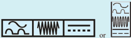
RCDs of type B shall be used in case where the application may create smooth DC residual current, or contain frequencies higher than 50 Hz. For example, three-phase Class 1 devices containing a motor controlled by a three phase variable speed drive. This is the case of certain types of three phase air conditioner, or pumps, or when supplying an electric vehicle.
For RCDs with rated residual current strictly higher than 30 mA, the RCD standards define a selective RCD, also known as type S. Such devices are delayed as they are able to withstand a residual current during a specified time without tripping. Type S residual current device can withstand 2 times I Δ n during 60 ms without tripping.
Electrical shock is a physiological reaction caused by electric current passing through the human body. Usually electrical shock occurs when body part comes in contact with a live conductor. The severity of the shock depends on the magnitude of the current, the parts of the body through which the current flows and the duration of the current flow.
IS/IEC 60479-1 defines four zones of current-magnitude/time-duration, in each of which the pathophysiological effects are described (see Fig. A-1). Any person coming into contact with live conductive part risks an electric shock. Curve C1 shows that when a current greater than 40 mA passes through a human being from one hand to feet. The person concerned is likely to die unless the current is interrupted in a relatively short time.
NOTE — In fact, the asymptote of curve C1 is 40 mA. The RCDs of 30 mA trip at 30 mA maximum and therefore, have a safety margin compared to the maximum dangerous value.
The point 500 ms/100 mA close to the curve C1 corresponds to a probability of heart fibrillation of the order of 0.14 percent.
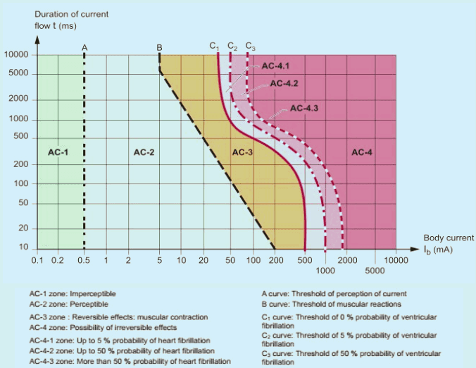
Fig. A-1 Pathophysiological Effects in Four Zones of Current-Magnitude/Time-Duration
SP 30 : 2023
Accidents from electricity especially ignition of fire from electricity in buildings is a major electrical safety hazard which require careful design, selection and erection of an electrical installation. This section explains the methods which need to be implemented to reduce such accidents.
This section of the code (Part 1/Sec 11) deals with protection against thermal effects. It is based on 4.3 of IS 732, which is a basic safety standard that applies to the protection of an installation from thermal effects.
Additional measures required are explained in this section.
This section also recommends usage of arc fault detection devices (AFDDs) for household and similar uses, intended to be used in a.c. circuits, for rated voltages not exceeding 240 V a.c, with rated frequencies of 50 Hz, 60 Hz or 50/60 Hz and rated currents not exceeding 63 A.
An AFDD is designed by the manufacturer:
a) either as a single device with provision of operating the protected circuit under specified conditions;
b) as a single device integrating a protective device; or
c) as a separate unit, according to Annex D of IS 17121, assembled on site with a declared protective Device.
NOTE — Refer IS 17121, for further details.
The standards listed below contain provisions which, through reference in this text, constitute provision of this standard. At the time of publication, the edition indicated were valid. All standards are subject to revision and parties to agreement based on this standard are encouraged to investigate the possibility of applying the most recent editions of the standards.
IS/IEC No.
Title
732 : 2019
Code of practice for electrical wiring installations
17121 : 2019/IEC 62606 : 2017
General requirements for arc fault detection devices
For the purposes of this standard, the terms and definitions given in IS 12640 (Part 1), IS 12640 (Part 2), IS/IEC 60898-1, IEC TR 60755 and IEC 62423 and the following shall apply.
NOTE — Where the terms “voltage” or “current” are used, they shall imply rms. values, unless otherwise specified.
3.1 Arc/Arcing — Luminous discharge of electricity across an insulating medium, usually accompanied by the partial volatilization of the electrodes.
NOTE — A complete sinusoidal current half cycle is not considered to be an arcing half cycle.
3.2 Arc Fault/Arcing Fault — Dangerous unintentional arc.
3.3 Arc Fault Detection Device (AFDD) — Device intended to mitigate the effects of arcing faults by disconnecting the circuit when an arc fault is detected.
3.4 Arc Fault Detection Unit (AFD Unit) — Part of the AFDD ensuring the function of detection and discrimination of dangerous earth, parallel and series arc faults and initiating the operation of the device to cause interruption of the current.
3.5 Detection — Function consisting of sensing the presence of an arc fault current.
3.6 Interruption — Function consisting of bringing automatically the main contacts of the AFDD from the closed position into the open position, thereby interrupting the arc fault current(s) flowing through them.
3.7 Earth Arc Fault — Arc fault where the current is flowing from active conductor to the earth.
3.8 Parallel Arc Fault — Arc fault where the arc current is flowing between active conductors in parallel with the load of the circuit.
3.9 Series Arc Fault — Arc fault where the current is flowing through the load(s) of the final circuit protected by an AFDD.
3.10 Closed Position — Position in which the predetermined continuity of the main circuit of the AFDD is secured.
4.1.1 Persons, livestock and property shall be protected against damage or injury caused by heat or fire which may be generated or propagated in electrical installations by considering the requirements of this code and the instructions of equipment manufacturers.
4.1.2 The heat generated by electrical equipment shall not cause danger or harmful effects to adjacent fixed material or to material which may foreseeable be in proximity to such equipment. Electrical equipment shall not present a fire hazard to adjacent materials.
Damage, injury or ignition may be caused by following effects:
a) heat accumulation, heat radiation, hot elements;
b) reduction of the safe function of electrical equipment, for example, protective devices, such as protective switchgear, thermostats, temperature limiters, seals of cable penetrations and wiring systems;
c) overcurrent;
d) insulation faults and/or arcs causing interference;
e) harmonic currents;
f) lightning strikes (see the IS/IEC 62305 series of standards);
g) overvoltages (see 4.5.3 of IS 732); and
h) inappropriate selection or erection of equipment.
4.2.1 Necessary electrical equipment shall be restricted for use at these locations.
4.2.2 Electrical equipment shall be so selected and erected that its temperature in normal use and foreseeable temperature rise during a fault shall not cause a fire.
These arrangements may be affected by the construction of equipment or its conditions of installation.
Laboratory experiment shows that a leakage current above 250 mA causes fire ignitions. IS 732 have recommended for protection against such high leakage current.
Final circuits and current-using equipment shall be protected against insulation faults as follows:
a) In TN and TT systems, RCDs with a rated residual operating current I of 300 mA shall be used. Where resistive faults may cause a fire, for example, for overhead heating with heating film elements, the rated residual operating current shall be Ian-30 mA
b) In IT systems, insulation monitoring devices monitoring the whole installation or RCMs (residual current monitoring devices) in the final circuits, both with audible and visual signals, shall be provided.
Alternatively, RCDs with a rated residual operating current as specified in a) may be used. In the event of a second fault, see 4.2.11 of IS 732 for disconnection times.
Mineral insulated cables and busbar trunking systems are considered not likely to cause a fire from insulation faults and therefore, may not be protected. However, if used in environment having flammable material like flammable gases, the necessary leakage current protection measures should be provided.
NOTE — Cables with metallic coverings are recommended. The metallic covering should be connected to the protective conductor.
Accessible parts of electrical equipment within arm’s reach shall not attain a temperature likely to cause burns to persons and shall comply with the appropriate limit stated in Table 1. All parts of the installation in normal service likely to attain, even for short periods, temperatures exceeding the limits stated in Table 1 shall be guarded so as to prevent any accidental contact. However, the values in Table 1 do not apply to equipment complying with relevant Indian standards.
NOTE — Lower temperatures may be applicable where condition BA2 (children) applies.
| Sl No.(1) | Accessible Part(2) | Material of Accessible Surface(3) | Maximum Temperature °C(4) |
| i) | Hand-held means of operation | Metallic | 55 |
| Non metallic | 65 | ||
| ii) | Parts intended to be touched but not hand-held | Metallic | 70 |
| Non metallic | 80 | ||
| iii) | Parts which need not be touched for normal operation | Metallic | 80 |
| Non metallic | 90 |
Forced air heating systems shall be such that their heating elements, other than those of central storage heaters, cannot be activated until the prescribed air flow has been established and are deactivated when the air flow is less than the prescribed value. In addition, they shall have two temperature limiting devices independent of each other which prevent permissible temperatures from being exceeded in air ducts.
Supporting parts, frames and enclosures of heating elements shall be of non-combustible material.
All appliances producing hot water or steam shall be protected by design or erection against overheating in all service conditions. Unless the appliances comply as a whole with the appropriate IS standards, the protection shall be by means of an appropriate non-self-resetting device, functioning independently of the thermostat.
If an appliance has no free outlet, it shall also be provided with a device which limits the internal water pressure.
173
The frame and enclosure of space heating appliances shall be of non-combustible material.
NOTE — At operating areas with a fire risk, space heating appliances may not be operated if the air from these areas is guided through the appliance.
The side walls of radiant heaters should have a sufficient distance from flammable parts. In case of a reduction of the distance by a non-flammable partition, this partition should have a distance of at least 1 cm to the enclosure of the radiant heater and to flammable parts.
Unless otherwise declared by the manufacturer, radiant heaters should be mounted so that in the direction of radiation a safety distance of at least 2 m from flammable parts is ensured.
Fires by electrical installations are often initiated by arc faults that result from parallel arcs or series arcs caused by insulation defects between active conductors or loose terminal connections.
During a series arc fault, there is no leakage current to earth, therefore, RCDs cannot detect, such a fault. Moreover, the impedance of the series arc fault reduces the load current and the current remains below the tripping threshold of a circuit-breaker or a fuse.
In the case of a parallel arc between line and neutral conductor, the current is limited by the impedance of the installation and the arc itself. Therefore, the resulting fault current could be lower than the operating current of the overcurrent protective device.
Arc fault detection devices are capable of detecting fault conditions that result from a sustained arcing junction either limited by the available current from the distribution wiring (considered as parallel arc faults) or limited by a load within the protected circuit (considered as series arc faults).
In a.c. circuits, the use of arc fault detection devices (AFDD) in compliance with IS 17121 can further contribute to the reduction of risk to persons, livestock and property resulting from extensive fires being propagated from electrical installations and appliances.
The following three devices are specified in IS 17121:
a) AFDD as one single device, comprising an AFD unit and opening means and intended to be connected in series with a suitable short-circuit protective device declared by the manufacturer as complying with one or more of the following standards – IS/IEC 60898-1, IS 12640 (Part 2) or the IEC 60269 series;
b) AFDD as one single device, comprising an AFD unit integrated in a protective device complying with one or more of the following standards – IS/IEC 60898-1, IS 12640 (Part 2) or IEC 62423; and
c) AFDD comprised of an AFD unit and a declared protective device, intended to be assembled on site.
NOTE — Refer IS 17121, for further details of classifications of AFDD.
Special measures shall be taken to protect against the effects of arc fault in final circuits.
Arc fault detection devices (AFDDs) shall be provided for single-phase a.c systems with an operating current not higher than 63A at following:
a) in premises with sleeping accommodation;
b) In bedrooms and habitable rooms in kindergarten and day care centers for children, disabled and elderly people (for example, nurseries for children or old people’s homes);
c) In bedrooms or habitable rooms, in barrier-free accommodations for handicapped persons; and
d) In locations:
With risks of fire due to the nature of processed or stored materials, that is, BE2 locations, (for example, barns, wood-working shops, stores of combustible material.
With combustible constructional material, that is, CA2 locations (for example, wooden buildings).
with endangering of irreplaceable good.
In a.c. circuits, the use of arc fault detection devices (AFDD) in compliance with IS 17121 satisfies the abovementioned recommendation.
If used, an AFDD shall be placed at the origin of the circuit to be protected.
The use of AFDDs does not obviate the need to apply one or more measures provided in other clauses in this code.
Family rooms, dining rooms, living rooms, parlors, libraries, dens, sunrooms, recreation rooms, closets, hallways or other rooms where movement or placement of furniture or movement by persons increases the likelihood of damaged/exposed cables.
SP 30 : 2023
Safe and reliable electrical network is possible through the protection against overcurrent. This Section provides requirements for the protection of live conductors from the effects of overcurrent. This section describes how live conductors are protected by one or more devices for the automatic disconnection of the supply in the event of overload and short-circuit except where the conditions described in omission of devices for protection are met.
Assistance for this section has been derived from 4.4 of IS 732 ‘Protection for safety — Protection against overcurrent’.
This section of the code (Part 1/Sec 12) deals with protection against overcurrent. It is based on 4.4 of IS 732, which is a basic safety standard that applies to the protection of an installation from over current (overload and short circuit current). The fundamental rule of protection against over current, according to 4.4 of IS 732 is applicable.
Additional measures required are explained in this section.
The standards listed below contain provisions which, through reference in this text, constitute provision of this standard. At the time of publication, the editions indicated were valid. All standards are subject to revision and parties to agreement based on this standard are encouraged to investigate the possibility of applying the most recent editions of the standards.
IS/IEC No.
Title
732 : 2019
Code of practice for electrical wiring installations
17345 (Part 1) : 2020
Powertrack systems: Part 1 General requirements
IS/IEC 61439-6
Low-voltage switchgear and controlgear assemblies: Part 6 Busbar trunking systems (busways)
Protective devices shall be provided to disconnect any overcurrent in the circuit conductors before such a current could cause danger due to thermal or mechanical effects detrimental to insulation, joints, terminations or material surrounding the conductors.
4.1.1 Detection of overcurrent shall be provided for all line conductors, and it shall cause the disconnection of the conductor in which the overcurrent is detected but not necessarily other live conductors; except where, disconnection of a single phase may cause danger, for example in the case of a three-phase motor.
4.1.2 In a TT or TN system, for a circuit supplied between line conductors and in which the neutral conductor is not distributed, overcurrent detection need not be provided for one of the line conductors, provided that the following conditions are simultaneously fulfilled:
a) there exists, in the same circuit or on the supply side, protection intended to detect unbalanced loads and intended to cause disconnection of all the line conductors; and
b) the neutral conductor is not distributed from an artificial neutral point of the circuits situated on the load side of the protective device mentioned in (a).
Protection of the neutral conductor in TT and TN systems shall be as per Table 1.
| Neutral Conductor⁽²⁾⁽³⁾ | Over Current Detection | Short Circuit Protection | |
| Cross Section Area | Current | ||
| `=Line conductor | <= Line conductor | Not necessary | Required |
| < Line conductor | <= Line conductor | Necessary⁽¹⁾ | Required |
| All possibility | > Line conductor⁽⁴⁾⁽⁵⁾ | Necessary⁽¹⁾ | Required |
| ¹⁾ Appropriate to the cross-sectional area of that conductor; this detection shall cause the disconnection of the line conductors, but not necessarily of the neutral conductor. ²⁾ If Protection is achieved by overcurrent protective devices in the line conductors, it is not necessary to provide overcurrent disconnecting device for the neutral conductor. ³⁾ PEN conductor should never be disconnected. ⁴⁾ Caused due to harmonic content in line current. ⁵⁾ Current in the neutral conductor is expected to exceed the Iz of that conductor. | |||
In IT systems, it is strongly recommended that the neutral conductor should not be distributed. If the neutral conductor is distributed and no protection is provided on the supply side/origin of the installation, overcurrent detection shall be provided for the neutral conductor of every circuit and this shall cause the disconnection of all the live and neutral conductors of the corresponding circuit.
This measure is not necessary if the particular circuit is protected by a residual current device (RCD) with a rated residual current not exceeding 0.20 times current carrying capacity(IZ) of the neutral conductor.
NOTE — In IT systems, it is strongly recommended that the neutral conductor should not be distributed.
The neutral conductor shall not be disconnected before the line conductors and shall be reconnected at the same time as or before the line conductors.
4.4.1 The operating characteristics of overcurrent protective devices shall comply with those specified in, for example, IS 12640 (Part 2), IS 13703 (Part 2), IS 13730 (Part 4), IS/IEC 60898, IS/IEC 60947-2, IS/IEC 60947-3, IS/IEC 60947-6-2 or IEC 60269-3.
4.4.2 Devices ensuring overload current protection only may have an interrupting capacity below the prospective short-circuit current at the point where the devices are installed.
4.4.3 Devices with short-circuit current protection only shall comply with requirements of 4.4.1 where in overload protection is achieved by other means or overload protection to be dispensed with as per 5 of this section.
4.4.4 The operating characteristics of overcurrent protective devices shall comply with those specified in, for example, IS/IEC 60898, IS/IEC 60947-2, IS/IEC 60947-6-2, IS 12640 (Part 2), IS 13703 (Part 2), IEC 60269-3, IS 13730 (Part 4) or IS/IEC 60947-3.
4.5.1 Coordination between Conductors and Overload Protective Devices
A device protecting a cable against overload shall satisfy the two following conditions:
4.6.1 The prospective short-circuit current at every relevant point of the installation shall be determined by calculation or by measurement.
NOTE — The prospective short-circuit current at the supply point may be obtained from the supply utility.
4.6.2.1 The rated breaking capacity shall be not less than the prospective maximum short-circuit current at the place of its installation, except where the following paragraph applies.
4.6.2.2 A lower rated breaking capacity is permitted if another protective device having the necessary breaking capacity is installed on the supply side. In that case energy let through by these two devices does not exceed the withstood limit of the device and conductor on the load side.
4.6.2.3 For cables and insulated conductors, short-circuit current interruption time shall not exceeding the permitted limit temperature of the insulation of the conductor.
For operating times of protective devices <0.1 s where asymmetry of the current is of importance and for currentlimiting devices k 2 S 2 ~ > I 2 t (let-through energy) of the protective device.
For short-circuits of duration up to 5 s , the time t, in which short-circuit current will raise the insulation of the conductors from the highest permissible temperature to the limit temperature shall be calculated from the formula:
4.7.1 A device ensuring protection against overcurrent shall be placed at the point where a change, such as a change in cross-sectional area, nature, method of installation or in constitution, causes a reduction in the value of current-carrying capacity of the conductors.
4.7.2 The protection device may be placed other than 4.7.1, under the following conditions,
In the part of the conductor between the point of reduction of cross-sectional area or other change and the position of the protective device there shall be no branch circuits nor socket-outlet circuits and that part of the conductor shall:
a) not exceed 3 m in length, and
b) be installed in such a manner as to reduce the risk of a short-circuit to a minimum, and to reduce risk of fire or danger to person.
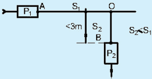
NOTE — S – Cross section area of conductor
Fig. 2 Limited Change of Position of Short-Circuit Protective Device (P2) on the Branch Circuit
c) not be placed close to combustible material.
4.7.3 A protective device may be placed on the supply side provided that it protects the wiring situated on the load side against short-circuit.
The requirements of 4.4, 4.5 and 4.6 apply, to the overload protective and short-circuit protective device.
The characteristics of the devices shall be coordinated so that the energy let through by the short-circuit protective device does not exceed that which can be withstood without damage by the overload protective device.
NOTE — This requirement does not exclude the type of coordination specified in IS/IEC 60947 series.
Conductors are considered to be protected against overcurrent when they are supplied from a source incapable of supplying a current exceeding the I of the conductors (for example, certain bell transformers, certain welding transformers and certain types of thermoelectric generating sets).
Reliability of electrical network throughout its service life is possible only by protecting it from different kinds of over voltages. This section provides requirements for the protection against over voltages, the maximum allowed over voltages in a network and the selection and erection of an SPD in an installation.
Assistance for this section has been derived from 4.5 and 5.3.5 of IS 732.
This section of the code (Part 1/Sec 13) covers protection against voltage disturbances, electromagnetic disturbances and voltage surges. It is based on 4.5 and 5.3.5 of IS 732, which is a basic safety standard that applies to the safety of persons, livestock and property against dangers and damage which may arise in the reasonable use of electrical installations and to provide for the proper functioning of those installations.
Requirements for protection of low-voltage installations against temporary over voltages due to earth faults in the high-voltage system and due to faults in the low-voltage system shall be in accordance with 4.5.2 of IS 732.
Requirements for protection against transient overvoltages of atmospheric origin or due to switching shall be in accordance with 4.5.3 of IS 732. Additional measures required are explained in this section.
3.1.1.1 Urban environment — Area with a high density of buildings or densely populated communities with tall buildings (for example, a town centre is an example of an urban environment).
3.1.1.2 Suburban environment — Area with a medium density of buildings (for example, Town outskirts are an example of a suburban environment).
3.1.1.3 Rural environment — Area with a low density of buildings.
3.1.1.4 Surge protective device (SPD) — Device that contains at least one non-linear component that is intended to limit surge voltages and divert surge currents.
3.1.1.5 Calculated risk level (CRL) — Calculated value of risk used to evaluate the need for transient overvoltage protection.
3.1.1.6 Rated impulse voltage (U ) — Impulse withstand voltage value assigned by the manufacturer to the equipment or to a part of it, characterizing the specified withstand capability of its insulation against transient over voltages.
3.1.1.7 Overvoltage control — Protection against transient overvoltage shall be provided where the consequence caused by overvoltage affects:
a) human life, for example, safety services, medical care facilities;
b) public services and cultural heritage, for example, loss of public services, IT centers, museums; and
c) commercial or industrial activity, for example, hotels, banks, industries, commercial markets, farms.
For all other cases, a risk assessment according to 3.2 shall be performed in order to determine if protection against transient overvoltage is required. If the risk assessment is not performed, the electrical installation shall be provided with protection against transient overvoltage.
SP 30 : 2023
Protection against switching over voltages should be considered in the case of equipment likely to produce switching over voltages or disturbances exceeding the values according to the overvoltage category of the installation for example, where a LV generator supply the installation or where inductive or capacitive loads (for example, motors, transformers, capacitor banks, etc.), storage units or high current loads are installed.
NOTE — Annex C provides guidance for overvoltage control where utility provided SPDs are installed on overhead lines.
For a low-voltage installation supplied from a high-voltage distribution network through a separate transformer (that is, an industrial application), additional means for protection against overvoltages due to lightning should be installed on the high-voltage side of the transformer.
Protection against transient overvoltage shall be provided where over voltages affect individuals for example, residential buildings and small offices if the risk assessment according to 3.2 requires the protection against transient over voltages of atmospheric origin.
If no risk assessment is performed protection against transient over voltages of atmospheric origin shall be provided, except for single dwellings where only overvoltage category III or IV equipment are the only equipment at this location.
5.1.1 Where a drop in voltage, or a loss and subsequent restoration of voltage could imply dangerous situations for persons or property, suitable precautions shall be taken. Also, precautions shall be taken where a part of the installation or current-using equipment may be damaged by a drop in voltage.
An undervoltage protective device is not required if damage to the installation or to current-using equipment is considered to be an acceptable risk, provided that no danger is caused to persons.
5.1.2 The operation of undervoltage protective devices may be delayed if the operation of the appliance protected allows without danger a brief interruption or loss of voltage.
5.1.3 If use is made of contactors, delay in their opening and reclosing shall not impede instantaneous disconnection by control or protective devices.
5.1.4 The characteristics of the undervoltage protective device shall be compatible with the requirements of the relevant standards for starting and use of equipment.
5.1.5 Where the reclosure of a protective device is likely to create a dangerous situation, the reclosure shall not be automatic.
187
| IS No/Other Publication | Title |
|---|---|
| 732 : 2019 | Code of practice for electrical wiring installations (fourth revision) |
| 13252 (Part 1) : 2010/IEC 60950-1 : 2005 | Information technology equipment — Safety — Part 1 General requirements (second revision) |
| 14493 (all Parts) | Multicore and symmetrical pair/quad cables for digital communication |
| 14700 (Part 6/Sec 1) : 2019/IEC 61000-6-1 : 2016 | Electromagnetic compatibility (EMC) — Part 6 Generic standards, Section 1 Immunity standard for residential, commercial and light-industrial environments (first revision) |
| 14700 (Part 6/Sec 2) : 2019/IEC 61000-6-2 : 2016 | Electromagnetic compatibility (EMC) — Part 6 Generic standards, Section 2 Immunity standard for industrial environments (first revision) |
| 14700 (Part 6/Sec 3) : 2018/IEC 61000-6-3 : 2018 | Electromagnetic compatibility (EMC) — Part 6 Generic Standards — Section 3 Emission standards for residential, commercial and light-industrial environments (first revision) |
| 16463 (Part 11) : 2016 | Low - voltage surge protective devices — Part 11 Surge protective devices connected to low — Voltage power systems — Requirements and test methods |
| 16463 (Part 12) : 2017 | Low - voltage surge protective devices — Part 12 Surge protective devices connected to low — Voltage power distribution systems — Selection and application principles |
| IS/IEC 60479-1 : 2018 | Effects of current on human beings and livestock: Part 1 General aspects |
| IS/IEC 62305 (all parts) | Protection against lightning (all parts) |
| IEC 60364-4-44 : 2018 | voltage electrical installations — Part 4-44: Protection for safety — Protection against voltage disturbances and electromagnetic disturbances |
| IEC 60664-1 : 2020 | Insulation coordination for equipment within low-voltage supply systems — Part 1: Principles, requirements and tests |
| IEC 60050-195 : 2021 | International electrotechnical vocabulary (IEV) — Part 195: Earthing and protection against electric shock |
| IEC 60050-826 : 2004 | International electrotechnical vocabulary (IEV) — Part 826: Electrical installations |
| IEC TR 61000-2-5 : 2017 | Electromagnetic compatibility (EMC) — Part 2-5: Environment — Description and classification of electromagnetic environments |
| IEC 61000-5 (all sections) | Electromagnetic compatibility (EMC) — Part 5: Installation and mitigation guidelines |
| IEC 61000-6-4 : 2018 | Electromagnetic compatibility (EMC) — Part 6-4: Generic standards — Emission standard for industrial environments |
| IEC 61936-1 : 2021 | Power installations exceeding 1 kV AC and 1.5 kV DC — Part 1: AC |
| IEC TR 62066 : 2002 | Surge overvoltages and surge protection in low-voltage a.c. power systems — General basic information |
| ISO/IEC 30129 : 2015 | Information technology — Telecommunications bonding networks for buildings and other structures |
SP 30 : 2023
Requirements for measures against electromagnetic influences shall be in accordance with 4.5.4 of IS 732. Additional measures required are explained in this section.
Power supply cables (or conductors), and information and communication technology cables which share the same cable management system or the same route, shall be installed according to the requirements of 4.1.
NOTE — For the purposes of this subclause, cable management systems are considered to include busbar trunking systems. Electrical safety and electromagnetic compatibility may produce different requirements for electrical segregation and electrical separation. Electrical safety always has the higher priority.
The following requirements apply unless 4.3 applies.
Where the specification and/or intended application of the information and communication technology cable is not available, the cable separation distance between the power and information and communication technology cables shall be not less than 200 mm in free air, provided:
a) the total current in a LV cable or in a bundle of LV cables does not exceed 600 A,
b) the applications supported by the cabling are designed to operate using the information and communication technology cabling installed or to be installed, and
c) the information and communication technology cables are: balanced cables having electromagnetic immunity performance in accordance with IEC 61156 (all parts) for Category 5 and above, or coaxial cables having electromagnetic immunity performance in accordance with IEC 61196-7.
In all other cases, the requirements and recommendations of 7.9.2 of ISO/IEC 14763-2, apply.
The 200 mm separation distance may be reduced according to Table 2.
Where a screened power cable is used, the separation distance may be reduced in accordance with the specification provided by the screened power cable manufacturer, provided that the screen is earthed at both ends.
Power cables that also carry information are not considered to be information and communication technology cables.
183
Table 2 Summary of Minimum Separation Distances where the Specification and/or Intended Application of the Information and Communication Technology Cable is not available
(Clause 4.2)
| Containment applied to the power supply cabling | |||
| Separation without electromagnetic barrier | Open metallic Containmenta)A | Perforated metallic containmentb) | Solid metallic containmentc) |
| 200 mm | 150 mm | 100 mm | 0 mm |
| a) Applicable to containment with screening performance (DC-100 MHz) equivalent to welded mesh steel basket of mesh size 50 mm × 100 mm.This screening performance is also achieved with steel tray even if the wall thickness is less than 1.0 mm and/or the evenly distributed perforated area is greater than 20 percent. | |||
| b) Applicable to containment with screening performance (DC-100 MHz) equivalent to steel tray of at least 1.0 mm wall thickness and no more than 20 percent evenly distributed perforated area. The screens or armouring of power cables are considered to act as perforated metallic containment if they do not meet this constructional equivalent of solid metallic containment. | |||
| c) Applicable to containment with screening performance (DC-100 MHz) equivalent to a steel conduit of at least 1.5 mm wall thickness. | |||
The minimum separation between the ICT cables and power supply cables shall include all allowances for cable movement between their fixing points or other restraints (see example in Fig. 2).
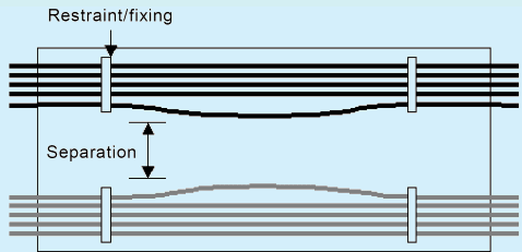
Fig. 2 Example of Cable Separation Distance
The minimum separation requirement applies in three dimensions. However, where information and communication technology cables and power supply cables are required to cross and required minimum separation cannot be maintained then the angle of their crossing shall be maintained at approximately 90° on either side of the crossing for a distance no less than the applicable minimum separation requirement.
No segregation is required between information and communication technology cabling and power supply cabling (other than 5.2 of IS 732) provided that the information and communication technology cabling is application(s)- specific and the application(s) support(s) a zero segregation relaxation.
No segregation is required between information and communication technology cabling and power supply cabling where all the following conditions are met the:
a) information and communication technology cables are in accordance with IEC 61156 (all parts) for Category 5 and above, or are coaxial cables having electromagnetic immunity performance in accordance with IEC 61196-7;
b) environmental classification of the space containing the information and communication technology cabling complies with electromagnetic classification E1 of ISO/IEC TR 29106 (or ISO/IEC 11801-1); and
c) power supply conductors comprising a circuit are either:
within an overall sheath and provide a total current no greater than 100 A, or
twisted, taped or bundled together and provide a total power no greater than 10 kVA.
Ground flash density N g = 1
Environmental factor f e n v = 8 5
Risk assessment length Lp = 2 LPAL + LPCL + 0.4 LPAH + 0.2 LPCH
= (2 × 0. 4) + (0. 4 × 0. 6)
Where,
L P A L = the length (km) of low-voltage overhead line= 0.4;
L P A H = the length (km) of high-voltage overhead line= 0.6;
L = the length (km) of low-voltage underground cable = 0; and
L = the length (km) of high-voltage underground cable = 0.
CRL = f env / (L P × N g) = 8 5 / (1. 0 4 × 1) = 8 1. 7
In this case, SPD protection shall be installed as the CRL is less than 1 000.
Ground flash density N g = 0 . 4
Environmental factor f e n v = 8 5
Risk assessment length Lp = 2 LpAL + LpCL + 0.4 LpAH + 0.2 LpCH
Where,
L P A L = the length (km) of low-voltage overhead line = 0;
L P A H = the length (km) of high-voltage overhead line = 0;
L P C L is the length (km) of low-voltage underground cable = 0; and
L P C H is the length (km) of high-voltage underground cable = 1.
CRL = f env / (L p × N g) = 8 5 / (0. 2 × 0. 4) = 1 0 6 2. 5
In this case, SPD protection is not mandatory as the CRL is greater than or equal to 1 000.
Ground flash density N g = 1
Environmental factor f e n v = 8 5 0
Risk assessment length Lp = 2 LPAL + LPCL + 0.4 LPAH + 0.2 LPCH
= 2 × 0. 4 + 0. 4 × 0. 6
Where,
L P A L = the length (km) of low-voltage overhead line = 0.4;
LPAH = the length (km) of high-voltage overhead line = 0.6;
LPCL = the length (km) of low-voltage underground cable = 0; and
LPCH = the length (km) of high-voltage underground cable = 0.
CRL = f env / (L p × N g) = 8 5 0 / (1 × 1. 0 4) = 8 1 7
In this case, SPD protection shall be installed as the CRL is less than 1 000.
SP 30 : 2023
Ground flash density N g = 0 . 5
Environmental factor f e n v = 8 5 0
Risk assessment length Lp = 2 LPAL + LPCL + 0.4 LPAH + 0.2 LPCH
= 1
Where,
L P A L = the length (km) of low-voltage overhead line = 0;
LPAH = the length (km) of high-voltage overhead line = 0;
L = the length (km) of low-voltage underground cable= 1; and
LPCH = the length (km) of high-voltage underground cable = 0.
CRL = f /(L × N ) = 850/(1 × 0.5) = 1 700.
In this case, an SPD is not mandatory as the CRL is greater than or equal to 1 000.
Where an installation is supplied by, or includes, an overhead line and an SPD is required for over voltage control, the protective control of the overvoltage level may be obtained either by installing surge protective devices directly in the installation close to the origin of installation, or with the consent of the network operator, in the overhead lines of the supply distribution network.
As an example, the following measures may be applied:
a) in the case of overhead supply distribution networks, overvoltage protection is erected at network junction points and especially at the end of each feeder longer than 0.5 km. Surge protective devices should be erected at every 0.5 km distance along the supply distribution lines. Nevertheless, the distance between surge protective devices should in no case exceed 1 km;
b) if a supply distribution network is erected partly as overhead network and partly as underground network, overvoltage protection in the overhead lines should be applied in accordance with a) at each transition point from and overhead line to an underground cable;
c) in a TN distribution network supplying electrical installations, where the protective measure automatic disconnection of supply is applied, the earthing conductors of the surge protective devices connected to the line conductors are connected to the PEN conductor or to the PE conductor; and
d) in a TT distribution network supplying electrical installations, where the protection measure automatic disconnection of supply is applied, surge protective devices are provided for the line conductors and for the neutral conductor. At the place where the neutral conductor of the supply network is effectively earthed, a surge protective device for the neutral conductor is not necessary.
Where overvoltage protection according to 4.5.3 of IS 732 is required, where the lines entering the building are overhead and where the case of lightning strike to the last pole of the overhead lines close to the building is taken into account, SPDs at the origin of the installation shall be selected according to Table D-1.
| Connection | Iimp (kA) | |||
| Supply system | ||||
| Single phase | Three phase | |||
| CT1 | CT2 | CT1 | CT2 | |
| L-N | - | 5 | - | 5 |
| L-PE | 5 | - | 5 | - |
| N-PE | 5 | 10 | 5 | 20 |
| NOTE - This table refers to lightning protection levels III and IV. | ||||
D-2 Where class I tested SPDs are required at or near the origin of the installation as per IS/IEC 62305, one of the following cases applies:
a) Where no risk analysis according to IS/IEC 62305-2 has been carried out, the impulse discharge current ( I i m p ) shall be not less than as given in Table D-2.
b) Where the risk analysis according to IS/IEC 62305-2 has been carried out, the impulse discharge current ( I i m p ) shall be determined according to the IS/IEC 62305 series.
Table D.2 Selection of Impulse Discharge Current ( I i m p ) where the Building is Protected against Direct Lightning Strike
| Connection | IIMP in kA | |||
| Supply System | ||||
| Single Phase | Three Phase | |||
| CT1 | CT2 | CT1 | CT2 | |
| L-N | 12.5 | 12.5 | ||
| L-PE | 12.5 | 12.5 | ||
| N-PE | 12.5 | 25 | 12.5 | 50 |
| NOTE - This table refers to lightning protection level (LPL) III and IV | ||||
SP 30 : 2023
Circuit calculations are performed for checking the adequacy of the electrical equipment for any electrical system that is characterized by the type of distribution system comprising of transformers, bus, cables etc.
The essential requirements and methods associated with following calculations are covered in this Section:
a) Short circuit calculations in 3 phase ac systems,
b) Calculation of the effects of short circuit currents, and
c) Current carrying capacity and voltage drop calculation for cables and flexible cords
Assistance for this Section has been derived from IS 13234, IS 13235 and IEC 60364-5-52.
This section of the code (Part 1/Sec 14) covers guidelines and general requirements associated with circuit calculations, namely, short circuit current calculations, short circuit impedance, electromagnetic and thermal effects of short circuit currents and voltage drop calculations for cables and flexible cords.
NOTE — Information on cascading, limitation and selectivity is given at Annex A.
IS No./Other Publications Title
2086 : 1993 Carriers and bases used in rewirable type electric fuses for voltages up to 650 V — Specification (third revision)
9926 : 1981 Specification for fuse-wire used in rewirable type electric fuses up to 650 volts
12640 (Part 1) : 2016/ Residual current operated circuit breakers without integral overcurrent IEC 61008-1 : 2013 protection for household and similar uses (RCCBs): Part 1 General rules (second revision)
12640 (Part 2) : 2016/ Residual current operated circuit-breakers with integral overcurrent protection IEC 61009-1 : 2013 for household and similar uses (RCBOs): Part 2 General rules (second revision)
13703 (Part 2/Sec 1) : 1993/ Specification for low-voltage fuses for voltages not exceeding 1 000 V IEC Pub 269-2 (1986) a.c. or 1 500 V d.c.: Part 2 Fuses for use by authorized persons, Section 1 Supplementary requirements
13703 (Part 2/Sec 2) : 1993/ LV fuses for voltages not exceeding 1 000 V a.c. or 1500 V d.c.: Part 2 Fuses IEC Pub 269-2-1 (1987) for use by authorized persons, Section 2 Examples of standardized fuses
13234 (Part 0) : 2017/ Short circuit currents in three-phase a.c. systems: Part 0 Calculation of currents IEC 60909-0 : 2016 (first revision)
13235 (Part 1) : 2019/ Short-circuit currents — Calculation of effects: Part 1 Definitions and IEC 60865-1 : 2011 calculation methods (first revision)
IS/IEC 60898-1 : 2015 Electrical accessories — Circuit breakers for overcurrent protection for household and similar installations: Part 1 Circuit breakers for a.c. operation (first revision)
IEC 60364-5-52 : 2009 Low-voltage electrical installations — Part 5-52: Selection and erection of electrical equipment — Wiring systems
3.1 This subject of circuit calculations covers the guidelines relating to the short circuit withstand capability of the electrical equipment and to check permissible voltage drop in cables and flexible cords upto the equipment terminals.
3.2 The objective of the circuit calculation is to ensure that the selection of equipment under consideration is designed for safe and reliable long period of operation.
3.3 The duration of flow of fault current in any section of the circuit should be considered as the maximum time required by the back-up protection to operate to isolate that particular section in case of flow of the calculated maximum short circuit current (maximum of all cases). This time will depend on the devices used for isolation e.g. in case of relays and circuit breakers, the total time from inception of fault till the interruption of the circuit by the circuit breaker including relay operation time should be considered.
4.1.1.1 A complete calculation of the short-circuit currents should give the currents as a function of time at the short circuit location from the initiation of the short circuit up to its end, corresponding to the instantaneous value of the voltage at the beginning of the short-circuit.
4.1.1.2 In most of the practical cases, it is sufficient to determine the rms value of symmetrical AC component and the peak value i p of short-circuit current following the occurrence of a short circuit. The value of [ i p ] depends on time constant of the decaying aperiodic component i p c with frequency depending on the X/R ratio of the shortcircuit impedance.
4.1.1.3 For determination of asymmetrical short–circuit breaking current, the decaying aperiodic component i p c may be calculated with sufficient accuracy by:
Where,
I k ′ ′ = initial symmetrical short circuit current (A);
f = nominal system frequency (Hz);
t = time duration of fault(s); and
τ = time constant based on system X/R.
4.1.1.4 The calculations of maximum and minimum short circuit current are based on the following considerations:
a) For the duration of the short-circuit there is no change in the number of circuits involved, that is, a three phase short-circuit remains as three phase and similarly a line-to-earth short-circuit remains line-to-earth during the short circuit;
b) Tap changers of the transformer are at nominal position; and
c) Arc resistances are not taken into account.
4.1.1.5 In situations where there will be no significant change in ac component decay due to far distance from generator (see Fig. 1), short-circuit current can be considered as the sum of the following two components:
a) The ac component with constant amplitude during the whole short-circuit; and
b) The aperiodic component beginning with initial value A and decaying to zero.
4.1.1.6 For the systems where there will be significant change in ac component decay due to close location near generator (see Fig. 2), short circuit-current can be considered as the sum of the following two components:
a) The a.c. component with decaying amplitude during the whole short circuit; and
b) The aperiodic component beginning with initial value A and decaying to zero.
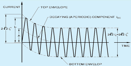
Fig. 1 Short-Circuit Current at a System Far-from Generator
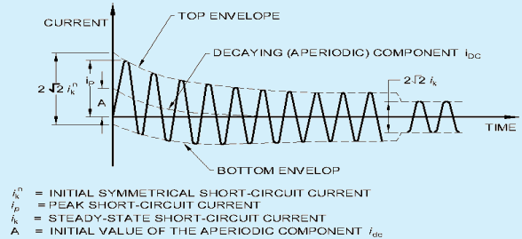
Fig. 2 Short-Circuit Current at a System Near-to Generator
Equivalent circuits are to be drawn for the system before calculation of short circuit currents with example as per Fig. 3.
The balanced three-phase short-circuit of a three-phase ac system (see Fig. 4a) often leads to the highest values of prospective (available) short-circuit current and the calculation becomes particularly simple on account of the balanced nature of the short circuit.
In calculating the short-circuit current, it is sufficient to take into account only the positive sequence short-circuit impedance, Z ( 1 ) = Z k as seen from the fault location.
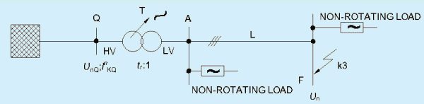
FIG. 3a SYSTEM DIAGRAM
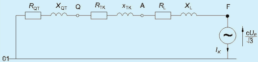
FIG. 3b EQUIVALENT CIRCUIT DIAGRAM OF THE POSITIVE-SEQUENCE SYSTEM
Fig. 3 Illustration for Calculating the Intial Symmetrical Short-Circuit i k ~ ~ in Compliance with the Procedure for the Equivalent Voltage Source
The following types of unbalanced (asymmetrical) short-circuits are to be considered:
a) line-to-line short-circuit without earth connection (see Fig. 4b);
b) line-to-line short-circuit with earth connection (see Fig. 4c); and
c) line-to-earth short-circuit (see Fig. 4d).
Normally, the three-phase short-circuit current is the largest among the above listed type of faults. In the event of short-circuit near to a transformer with neutral earthing or a neutral earthing transformer, the line-to-earth shortcircuit current may be greater than the three-phase short-circuit current. This applies in particular to transformers of vector group Yz, Dy and Dz when earthing the y-winding or z-winding on the low voltage side of the transformer.
In three-phase systems the calculation of the current values resulting from unbalanced short-circuits is simplified by the use of the method of symmetrical components which requires the calculation of three independent system components, avoiding any coupling of mutual impedances. Using this method, the currents in each line are found by superposing the currents of three symmetrical component systems:
a) positive-sequence current I ( 1 )
b) negative-sequence current I ( 2 ) and
In general, the initial symmetrical short-circuit current I k n D shall be calculated using the below equation with the equivalent voltage source C U n √( 3 ) at the short-circuit location and the short-circuit impedance Zk = Rk + j Xk
In network feeders, transformers, overhead lines, cables, reactors and similar equipment, positive-sequence and negative-sequence short-circuit impedances are equal: Z ( 1 ) = Z ( 2 ) .
The zero-sequence short-circuit impedance Z_₍₀₎ = U_₍₀₎ / I_₍₀₎ is determined by assuming an a.c. voltage between the three paralleled conductors and the joint return (for example, earth, earthing arrangement, neutral conductor, earth wire, cable sheath, and cable armouring). In this case, the three-fold zero-sequence current flows through the joint return.
While calculating the impedances, there shall be clear distinction between short-circuit impedances at the shortcircuit location and short-circuit impedances of individual electrical equipment (see Table 2).
The utilization of the current limiting capacity of a circuit-breaker at a given point to enable installation of lowerrated circuit-breakers in branch is known as ‘cascading’ or ‘back-up protection’. The main (upstream) circuitbreakers acts as a barrier against short-circuit currents and branch (downstream) circuit breakers with lower breaking capacities than the prospective short-circuit (at their point of installation) operate under their normal breaking conditions. The limiting circuit-breaker helps the circuit-breaker placed downstream by limiting high short-circuit currents thus, enabling use of downstream circuit-breaker with a breaking capacity lower than the short-circuit current calculated at its installation point and thereby, enabling economical selection of circuitbreakers.
Cascading concerns all devices installed downstream of the circuit-breaker, and can be extended to several consecutive devices, even if they are used in different switchboards. The upstream device must have an ultimate breaking capacity greater than or equal to the assumed short-circuit current at the installation point. For downstream circuit-breakers, the ultimate breaking capacity to be considered is the ultimate breaking capacity enhanced by coordination.
The association of the upstream and downstream circuit breakers allows an increase in performance of the breakers. Thus, the electromagnetic, electrodynamic and thermal effects of short-circuit currents are reduced. Installation of a single limiting circuit-breaker along with lower rated circuit-breakers results in considerable economy and simplification of installation work.
D r and D γ are the two circuit-breakers (see Fig. A-1). As soon as the two circuit-breakers trip (as from point I B ) 1 an arc voltage U A D I on separation of the contacts of D i is added to voltage U A D 2 and helps, by additional limitation, circuit-breaker D γ to open.
The association D 1 + D 2 allows an increase in performance of D 2 as shown in Fig. A-2, which depicts limitation curve of D _ 2 1 enhanced limitation curve of D_2 by D_1 and I c u D 2 enhanced by D i
Annex A of IS/IEC 60947-2 defines coordination under short-circuit conditions between circuit-breaker and another short-circuit protective device (SCPD) associated in the same circuit and the tests to be performed. Cascading is normally verified by tests for critical points. The tests are performed with an upstream circuit-breaker D r with a maximum overcurrent setting and a downstream circuit-breaker D z with a minimum setting.
A-2.1 The technique of limitation allows the circuit breaker to considerably reduce short-circuit currents. It ensures attenuation of the harmful electromagnetic, thermal and mechanical effects of short-circuits and is the basis of the cascading technique.
The assumed fault current I s c is the short-circuit current that would flow at the point of the installation where the circuit-breaker is placed, if there were no limitation. Since the fault current is eliminated in less than one half-period, only the first peak current (asymmetrical peak I) is considered. Reduction of this peak I to limited I L characterizes circuit-breaker limitation. Limitation consists of creating a back-electromotive force opposing the growth of the short-circuit current. Effectiveness of limitation depends on intervention time, that is the time t s when the back-electromotive force ( b e m f ) appears, the rate at which b e m f increases and the value of b e m f The backelectromotive force is the arc voltage ( U a ) due to the resistance of the arc developing between the contacts on separation. Its speed of development depends on the contact separation speed. As shown in Fig. A-3, as from the time t s when the contacts separate, less than the assumed fault current flow through when a short-circuit occurs.
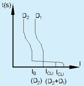
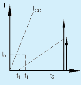
Fig. A-1 Operation of Circuit-Breakers in Cascade
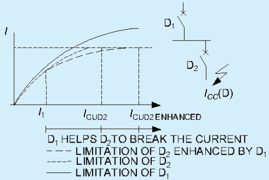
Fig. A-2 Limitation Curves for Circuit-Breakers
The circuit-breaker limitation capacity defines the way how it reduces the let through current in short-circuit conditions (see Fig. A-4 and Fig. A-5). The thermal stress of the limited current is the area (shaded) defined by the curve of the square of the limited current I s ~ 2 c ( t ) . If there is no limitation, this stress would be the area, far larger, that would be defined by the curve of the square of the assumed current. For an assumed short-circuit current I, limitation of this current to 10 percent results in less than 1 percent of assumed thermal stress. The cable temperature rise is directly proportional to the thermal stress.
NOTE — On a short-circuit, adiabatic temperature-rise of conductors occurs (without heat exchange with the outside due to the speed of the energy supply). The increased temperature for a conductor with a cross-section S is:
A circuit-breaker’s limiting capacity is expressed by limitation curves that give:
a) the limited peak current as a function of the rms current of the assumed short-circuit current. For example, on a 160 A feeder where the assumed 1 s c is 90 kA rms, the non-limited peak 1 s c is 200 kA (asymmetry factor of 2.2) and the limited I s c is 26 kA peak.
211
b) the limited thermal stress (in A2s) as a function of the rms current of the assumed short-circuit current. For example, on the previous feeder, the thermal stress moves from more than 1 0 0 × 1 0 6 A 2 s to 6 × 1 0 6 A 2 s
A-3.1 Selectivity is the co-ordination of the operating characteristics of two or more over-current protective devices such that, on the incidence of over-currents within stated limits, the device intended to operate within these limits does so, while the other(s) does (do) not (see Fig. A-6).
Distinction is made between series coordination or selectivity involving different over-current protective devices passing substantially the same over-current and network Selectivity involving identical protective devices passing different proportions of the overcurrent. In LV networks, Selectivity is recommended in order to obtain higher levels of supply continuity and protection, ensuring better safety of installations and minimum cost overruns.
Cascading principle in limiting CBs can enhance selectivity levels. It is recommended that the manufacturer provides the relevant data in terms of selectivity charts and cascading levels for various combination of CBs (upstream and downstream) and fault current as per the laboratory test results.
A selectivity current I is defined, such that if:
a) I f a u l t > I s : both circuit-breakers trip; and
b) I f a u l t < I s ; only D 2 eliminates the fault.
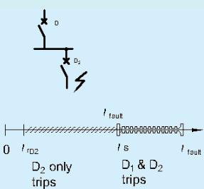
Fig. A-6 Selectivity and Sequence of Tripping
The value I s is compared with assumed I s c ( D 2 ) at point D 2 of the installation.
a) total coordination or selectivity coordination or selectivity: Is > Isc ( D2 ) ; coordination or selectivity coordination or selectivity is qualified as total, that is, whatever the value of the fault current, only D z eliminates it.
b) partial coordination or selectivity coordination or selectivity: I s < I sc ( D ₂); coordination or selectivity coordination or selectivity is qualified as partial, that is up to I s ° only D 2 eliminates the fault. Beyond I s ° both D i and D 2 open.
Where,
I s c ( D l ) ; short-circuit current at the point where D i is installed,
I c u : D 1 : ultimate breaking capacity of D i
A-3.3 Types of Selectivity
This technique is directly linked to the staging of the
Long Time (LT) tripping curves of two serial-connected circuit-breakers (see Fig. A-7).
t(s)
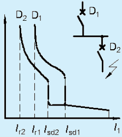
Fig. A-7 Current Selectivity
SP 30 : 2023
The Selectivity limit I s is:
a) I s = I s d 2 if the thresholds I s d 1 and I s d 2 are too close or merge; and
b) I s = I s d 1 if the thresholds I s d 1 and I s d 2 are sufficiently far apart.
Current Selectivity is achieved when:
a) I r 1 / I r 2 < 2
b) I s d 1 / I s d 2 > 2
The Selectivity limit being:
I s = I sd1
Selectivity is total, i f I s > I s c ( D 2 ) , that is I s ; d 1 > I s c ( D 2 )
This normally implies,
a relatively low level I s c ( D 2 ) ,
a large difference between the ratings of circuit-breakers D i and D 2 °
Current Selectivity is normally used in final distribution.
This is the extension of current selectivity and is obtained by staging over time of the tripping curves. This technique consists of giving a time delay of t to the Short Time (ST) tripping of D i (see Fig. A-8).
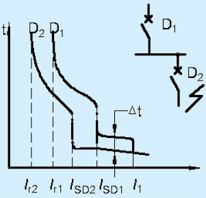
Fig. A-8 Time Selectivity
The thresholds ( I r 1 , I s d 1 ) of D i and ( I r 2 , I s d 2 ) comply with the staging rules of current Selectivity. The Selectivity limit I s of the association is at least equal to I i 1 ° the instantaneous threshold of D _ 1 .
For Selectivity on final and/or intermediate feeders, A category circuit-breakers can be used with time- delayed tripping of the upstream circuit-breaker. This allows extension of current Selectivity up to the instantaneous threshold I i l of the upstream circuit-breaker: Is> Ii1. If Isc( D _₂) is not too high (in case of a final feeder), total selectivity can be obtained.
On the incomers and feeders of the MSB, as continuity of supply takes priority, the installation characteristics allow use of B category circuit-breakers designed for time-delayed tripping. These circuit-breakers have a high thermal withstand ( I c w > 5 0 ) percent Icn for t=Is :Is>Icw1 . Even for high I s c ( D 2 ) , time Selectivity normally provides total Selectivity: I c w 1 > I s c ( D 2 )
NOTE — Use of B category circuit-breakers means that the installation must withstand high electrodynamic and thermal stresses. Consequently, these circuit-breakers have a high instantaneous threshold Ii that can be adjusted and disabled in order to protect the busbars if necessary.
A-3.4 Enhancement of Current and Time Selectivity
Use of a limiting downstream circuit-breaker enables the Selectivity limit to be pushed back.
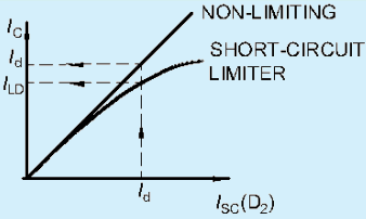
Fig. A-9 Enhancement of Selectivity
On referring to Fig. A-9, a fault current I d will be seen by D 1 ′
equal to I d for a non-limiting circuit-breaker, and equal to I L d < I d for a limiting circuit-breaker.
The limit of current and time Selectivity I s of the association D 1 + D 2 is, thus, pushed back to a value that increases when the downstream circuit-breaker is rapid and limiting.
Use of a limiting circuit-breaker is extremely effective for achievement of total selectivity when threshold settings (current selectivity) and/or the instantaneous tripping threshold (time selectivity) of the upstream circuit-breaker D i are too low with respect to the fault current I d in D 2 - I s c ( D 2 )
NATIONAL ELECTRICAL CODE OF INDIA
This type of Selectivity can be achieved with circuit-breakers equipped with specially designed electronic trip units. Only, the short time protection (STP) and ground fault protection (GFP) functions of the controlled devices are managed by logic selectivity. In particular, the Instantaneous Protection function (inherent protection function) is not concerned.
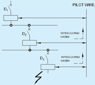
Fig. A-10 Logic Selectivity (ZSI)
SP 30 : 2023
a) Time delay: staging (if any) of the time delays of time Selectivity to be applied (t_D1>t_D2>t_D3) ,
b) Thresholds: natural staging of the protection device ratings must be complied with ( I c r D 1 > I c r D 2 > I c r D 2 )
NOTE — This technique ensures Selectivity even with circuit-breakers of similar ratings.
Activation of the logic Selectivity function is via transmission of information on the pilot wire for ZSI input:
a) Low level (no downstream faults) — The protection function is on standby with a reduced time delay (< 0.1s).
b) High level (presence of downstream faults) — The relevant protection function moves to the time delay status set on the device.
Activation of the logic Selectivity function is via transmission of information on the pilot wire for ZSI output:
Low level — The trip unit detects no faults and sends no orders.
High level — The trip unit detects a fault and sends an order.
A pilot wire connects in cascading form, the protection devices of an installation (see Fig. A-10). When a fault occurs, each circuit-breaker upstream of the fault (detecting a fault) sends an order (high level output) and moves the upstream circuit-breaker to its natural time delay (high level input). The circuit breaker placed just above the fault does not receive any orders (low level input) and thus, trips almost instantaneously.
This technique enables easy achievement as standard of selectivity on 3 levels or more, easy achievement of downstream Selectivity with non-controlled circuit-breakers, elimination of important stresses on the installation, relating to time-delayed tripping of the protection device, in event of a fault directly on the upstream busbars. All the protection devices are, thus, virtually instantaneous.
A-3.5 Selectivity Rules
For any overcurrent value, Selectivity is guaranteed on overload if the non-tripping time of the upstream circuitbreaker D i is greater than the maximum breaking time of circuit-breaker D 2
The condition is fulfilled if the ratio of Long Time (LT) and Short Time (ST) settings is greater than 2. The Selectivity limit Is is, at least, equal to the setting threshold of the upstream Short Time (ST) time delay.
A-3.5.2 Short-circuit Protection
Tripping of the upstream device D is time delayed by t, the conditions required for current Selectivity must be fulfilled and the time delay t of the upstream device D must be sufficient for the downstream device to be able to eliminate the fault. Selectivity increases the Selectivity limit I up to the instantaneous tripping threshold of the upstream circuit-breaker D1 (see Fig. A-11).
Selectivity is always total if circuit-breaker D is of category B, has an I c w characteristic equal to its I c u · Selectivity is total in the other cases if the instantaneous tripping threshold of the upstream circuit-breaker D is greater than the assumed I s c in D 2
Selectivity is always total.
There are no general Selectivity rules. The time/current curves clearly supply a value of I s c (limited or assumed) less than the short time tripping of the upstream circuit-breaker; selectivity is then total. If this is not the case, only tests can indicate selectivity limits of coordination, in particular when circuit-breakers are of the limiting type. The Selectivity limit I s is determined by comparison of curves:
a) in tripping energy for the downstream circuit breaker; and
b) in non-tripping energy for the upstream circuit-breaker.
The potential intersection point of the curves gives the Selectivity limit I . The manufacturers indicate in tables the tested performance of coordination.
A-3.6.1 According to the earthing system, Selectivity only uses coordination of overcurrent protection devices. When the insulation fault is treated, specifically, by earth leakage protection devices (for example, in the TT system), selectivity of the residual current devices (RCDs) with one another must also be guaranteed. Selectivity of earth leakage protection devices must ensure that, should an insulation fault occur, only the feeder concerned by the fault is de-energized. The aim is to optimize energy availability.
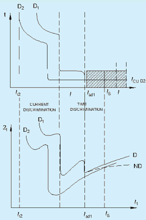
Fig. A-11 Selectivity at Various Fault Currents
A-3.6.2 Types of Earth Leakage Protection Selectivity
In view of requirements and operating standards, Selectivity must simultaneously meet both the time and current conditions (see Fig. A-12).
The RCD must trip between I and I n / 2 , where I is the declared operating current. There must therefore exist a minimum ratio of 2 between the sensitivities of the upstream device and the downstream device. In practice, the standardized values indicate a ratio of 3.
The minimum non-tripping time of the upstream device must be greater than the maximum tripping time of the downstream device for all current values.
NOTE — The tripping time of RCDs must always be less than or equal to the time specified in the installation standards to guarantee protection of people against indirect contacts.
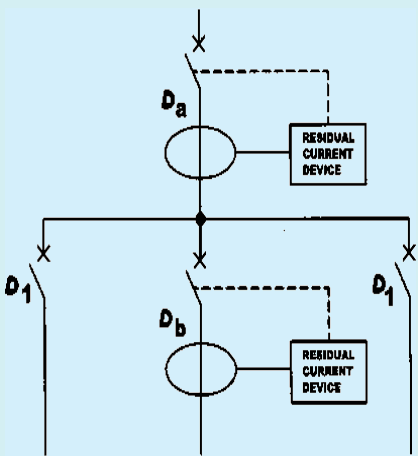
Fig. A-12 Vertical Coordination
For the domestic area, IS 12640 (Part 1) (residual current circuit-breakers) and IS 12640 (Part 2) (residual current devices) define operating times. The values in the table correspond to curves G and Curve S. Curve G (general) correspond to non-delayed RCDs and S (selective) to those that are voluntarily delayed (see Fig. A-13).
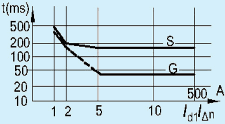
Fig. A-13 Operating Time Curves
Sometimes known as circuit selection, it allows savings at the supply end of the installation of an RCD placed in the cubicle if all its feeders are protected by RCDs. Only the faulty feeder is de-energized, the devices placed on the other feeders do not see the fault (see Fig. A-14).
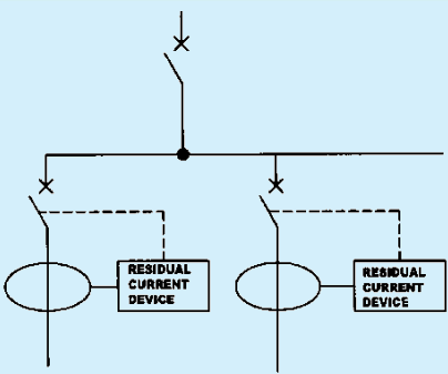
Fig. A-14 Horizontal Coordination
(Clause 3.6.2.2)
| Standardized Values of Operating Time | |||||||
| Type | In | I/Δ n | Standardized Values of Operating Time and Non-operating Time (in s) at: | ||||
| I Δ n | 2I Δ n | 5I Δ n | 500A | ||||
| General instantaneous | All values | All values | 0.3 | 0.15 | 0.04 | 0.04 | Maximum operating time |
| Selective | >25 | >0.030 | 0.5 | 0.2 | 0.15 | 0.15 | Maximum operating time |
| 0.13 | 0.06 | 0.05 | 0.04 | Maximum operating time | |||
SP 30 : 2023
With the calculation methods, forces on insulators, stresses in rigid conductors and tensile forces in slack conductors are to be estimated.
197
Currents in parallel conductors will induce electromagnetic forces between the conductors. When the parallel conductors are long compared to the distance between them, the forces will act evenly distributed along the conductors.
SP 30 : 2023
When the currents are in opposite directions the electromagnetic force is a repulsion which tends to induce deformations that would increase inductance of the circuit.
Where,
a) i 1 and i 2 are the instantaneous values of the currents;
b) l Center-line distance between the supports; and
c) a Center-line distance between the conductors.
The value of the force in a given direction can be calculated by considering the work done in the case of a virtual displacement in the actual direction. As the work is done by the electromagnetic force, it must be equal to the change in the energy in the magnetic field caused by this virtual displacement.
The force between two conductors is proportional to the square of the current, or to the product of the two currents. As the current is a function of time, the force will also be a function of time. In the case of a short-circuit current without a d.c. component the force will vary with twice the frequency of the current. A d.c. component in the short-circuit current will give rise to an increase of the peak value of the force and to a component of force varying with the same frequency as the current. The peak value of the force is of particular interest in the case of mechanically rigid structures.
The force will result in bending stress on rigid conductors, tension stress and deflection in flexible conductors and bending, compression or tension loads on the supports.
| Component | Impedance formula | Reference | |||||||||||
|---|---|---|---|---|---|---|---|---|---|---|---|---|---|
| Network feeder with known R/X ratio | ZQ = cUnQ√(3)IkQ''XQ = ZQ√1 + (RQ/XQ)2 | Network feeder with known R/X ratio, Fault on LV side of transformer | ZQt = cUnQ√(3)IkQ'' · 1tr2R<sub>Q</sub> = 0.1X<sub>Q</sub>XQ = 0.995ZQ. | Two winding transformer | ZT = ukr100 % · UrT2SrTRT = ukr100 % · UrT2SrT = PkrT3IrT2X<sub>T</sub> = √Z<sub>T</sub>² - R<sub>T</sub>² ZTK = KT ZT | Impedance correction factor,KT = 0.95 cmax1 + 0.6xT x<sub>T</sub> = X<sub>T</sub>/(U<sub>rT</sub>²/S<sub>rT</sub>)UrT is the rated voltage of the transformer on the high-voltage or low-voltage side;Irr is the rated current of the transformer on the high-voltage or low-voltage side;SrT is the rated apparent power of the transformer;PkrT is the total loss of the transformer in the windings at rated current;Ukr is the short-circuit voltage at rated current in per cent;URf is the rated resistive component of the short-circuit voltage in per cent. | SP 30 : 2023 Table 2 (Concluded) | Overhead lines and cables |
The conductors may be supported in different manners, either fixed or simple or in a combination of both, and may have two, three, four or several supports. Depending on the kind of support and the number of supports, the stress in the conductors and the forces on the supports will be different for the same short-circuit current.
The stresses in the conductors and the forces on supports also depend on the ratio between the natural frequency of the mechanical system ( f c ) and the frequency of the electromagnetic force ( f ) . Especially in the case of resonance, or near to resonance, the stresses and forces in the system may be amplified. I f f c / f < 0 . 5 the response of the system decreases and the maximum stresses are in the outer phases.
Bending stress caused by the forces between main conductors is given by:
A short-circuit current in a slack conductor will cause a tensile force in the conductor which will affect insulators, support structures and apparatus. It is necessary to distinguish between the tensile force during short-circuit and the tensile force after short circuit, when the conductor falls back to its initial position.
The heating of conductors due to short-circuit currents involves several phenomena of a non-linear character and other factors that have to be either neglected or approximated in order to make a mathematical approach possible. For the purpose of this calculation, the following assumptions can be made:
a) Proximity-effect (magnetic influence of nearby parallel conductors) is disregarded;
b) Resistance-temperature characteristic is assumed linear;
c) The specific heat of the conductor is considered constant; and
d) The heating is generally considered adiabatic.
The loss of heat from a conductor during the short-circuit is very low, and the heating can generally be considered adiabatic. Hence, the calculation for this can also be based on adiabatic conditions.
When repeated short-circuits occur with a short-time interval between them (that is rapid auto-reclosure) the cooling down in the short dead-time is of relatively low importance, and the heating can still be considered adiabatic. In cases where the dead-time interval is of longer duration (that is delayed auto-reclosure), the heat loss may be taken into account.
The calculation need not take into account the skin effect, that, is the current is regarded as evenly distributed over the conductor cross-section area. This approximation is not valid for large cross-sections, and therefore for cross-sections above 600 mm², the skin effect shall be taken into account.
NOTE — If the main conductor is composed of sub-conductors, uneven current distribution between the sub-conductors will influence the temperature rise of sub-conductors.
NATIONAL ELECTRICAL CODE OF INDIA
| System | ||||
| Type of Short-Circuit | Without Three-Phase Automatic Reclosing | With Three-phase Automatic Reclosing | With and Without Three-phase Automatic Reclosing | |
| VomVrm, VsVrs | VomVrm, VosVrs | VFVrm | ||
| First current flow | Second current flow | |||
| Line-to-line | 1.0 | 1.0 | 1.8 | range2.0 for σtot,d0.8fy ≤ 0.5 1 0.8fyσtot,d for 0.5 < σtot,d0.8fy < 1.0 21.0 for 1.0 ≤ σtot,d0.8fy 3 |
The current to be carried by any conductor for sustained periods during normal operation shall be such that the conductor operating temperature given in the appropriate table of current-carrying capacity in this section is not exceeded.
SP 30 : 2023
Where a conductor operates at a temperature exceeding 7 0 ° C it shall be ascertained that the equipment connected to the conductor is suitable for the conductor operating temperature.
Except for a ring final circuit, cables connected in parallel shall be of the same construction, cross sectional area, length and disposition, without branch circuits and arranged so as to carry substantially equal currents.
Where a cable is to be connected to a bare conductor or busbar its type of insulation and/or sheath shall be suitable for the maximum operating temperature of the bare conductor or busbar.
Where a cable is to be run in a space to which thermal insulation is likely to be applied, the cable shall, wherever practicable, be fixed in a position such that it will not be covered by the thermal insulation. Where fixing in such a position is impracticable, the cross-sectional area of the cable shall be appropriately increased.
For a single cable likely to be totally surrounded by thermally insulating material over a length of more than 0.5 m, the current-carrying capacity shall be taken, in the absence of more precise information, as 0.5 times the currentcarrying capacity for that cable clipped direct to a surface and open.
Where a cable is to be totally surrounded by thermal insulation for less than 0.5 m, the current-carrying capacity of the cable shall be reduced appropriately depending on the size of cable, length insulation and thermal properties of the insulation. The de-rating factors have to be appropriate to conductor sizes.
The metallic sheaths and/or non-magnetic armour of single-core cables in the same circuit shall be normally bonded together at both ends of their run (solid bonding). Alternatively, the sheaths or armour of such cables having conductors of cross-sectional area exceeding 50 mm2 and a non-conducting outer sheath may be bonded together at one point in their run (single point bonding) with suitable insulation at the un-bonded ends, in which case the length of the cables from the bonding point shall be limited so that, at full load, voltages from sheaths and/or armour to earth:
a) do not exceed 25 V;
b) do not cause corrosion when the cables are carrying their full load current; and
c) do not cause danger or damage to property when the cables are carrying short-circuit current.
The current-carrying capacity of cable for continuous service is affected by various environmental conditions. This clause provides correction factors in these respects as follows:
In practice the ambient air temperatures may be determined by thermometers placed in free air as close as practicable to the position at which the cables are installed or are to be installed, subject to the provison that the measurements are not to be influenced by the heat arising from the cables. Thus, if the measurements are made while the cables are loaded, the thermometers should be placed about 0.5 m or ten times the overall diameter of the cable whichever is the lesser, from the cables, in the horizontal plane, or 150 mm below the lowest of the cables.
Where cables are subject to such radiation due to solar or other infra-red, the current-carrying capacity may need to be specially calculated.
Appropriate correction factors to be applied to the manufacture declared current-carrying capacity where cables or circuits are grouped.
The current-carrying capacity of cable corresponds to the maximum current that can be carried in specified conditions without the conductors exceeding the permissible limit of steady state temperature for the type of insulation concerned.
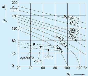
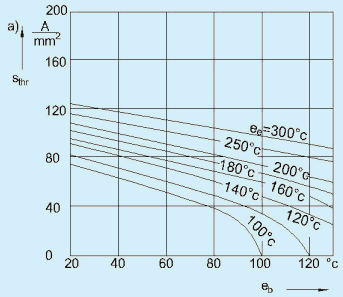
a) FULL LINES: COPPER DOTTED LINES: FLAT PRODUCT OF UNALLOYED STEEL AND STEEL CABLES
b) ALLUMINIUM, ALLUMINIUM ALLOY,ALLUMINIUM
CONDUCTOR STEEL REINFORCED (ACSR)
Fig. 8 Relation Between Rated Short-Time Current Density ( T k r = 1 S ) and Conductor Temperature
The values of current calculated represent the effective current-carrying capacity only where no correction factor is applicable. Otherwise, the current-carrying corresponds to the value multiplied by the appropriate factors for ambient temperature, soil thermal resistivity, grouping and thermal insulation, as applicable.
Irrespective of the type of over current protective device associated with the conductors concerned, the ambient temperature correction factors are to be used when calculating current-carrying capacity (as opposed to those used when selecting cable size).
Where overload protection is required, the type of protection provided does not affect the current- carrying capacity of a cable for continuous service (I ) but it may affect the choice of conductor size. The operating conditions of a cable are influenced not only by the limiting conductor temperature for continuous service, but also by the conductor temperature which might be attained during the conventional operating time of the overload protection device, in the event of an overload.
SP 30 : 2023
This means that the operating current of the protective device must not exceed 1.45I . Where the protective device is a fuse as per IS 13703 (Part 2/Sec 1) and IS 13703 (Part 2/Sec 2) or IS 2086 or a miniature circuit breaker as per IS/IEC 60898, this requirement is satisfied by selecting a value of z not less than I n ′
In practice, because of the standard steps in nominal rating of fuse and circuit breakers, it is often necessary to select a value of I n exceeding I b . In that case, because it is also necessary for I z in turn to be not less than the selected value of In, the choice of conductor cross-sectional area maybe dictated by the over load conditions and the current-carrying capacity (I ) of the conductors will not always by fully used.
The size needed for a conductor protected against overload by a fuse fix (IS 9926) in rewireable type fuse can be obtained by the use of a correction factor, 1.45/2 = 0.725 which results in the same degree of protection as that afforded by other overload protective devices. This factor is to be applied to the nominal rating of the fuse as a divisor, thus, indicating the minimum value of I required of the conductor to be protected. In this case also, the choice of conductor size is dictated by the overload conditions and the current carrying capacity (I ) of the conductors cannot be fully used.
Having established the design current ( I b ) of the circuit under consideration, the conductor size has to be sized necessarily from consideration of the conditions of normal load and overload is then determined. All correction factors affecting I z (that is, the factor for ambient temperature, grouping and thermal insulation) can, if desired, be applied to the values of I as multipliers. This involves a process of trial and error until a cross-sectional area is reached which ensures that I is not less than I b and not less than I n of any protective device it is intended to select. In any event, if a correction factor for protection by a semi-enclosed fuse is necessary, this has to be applied to I n as a divisor. It is, therefore, more convenient to apply all the correction factors to I n as divisors.
In polyphase circuits carrying balanced currents, the associated neutral conductor need not be taken into consideration. Where the neutral conductor in a multi-core cable carries current as a result of an unbalance in the phase currents, conductor shall have a cross-section area adequate to afford the current to be carried by any conductor for sustained periods during normal operation.
If the neutral conductor carries current without corresponding reduction in load of the phase conductors, the neutral currents may be caused by a significant harmonic current in three-phase circuits. If the harmonic content is greater than 10 percent the neutral conductor shall not be smaller than the phase conductors. Thermal Effects due to the presence of harmonic currents and the corresponding reduction factors for higher harmonic currents shall be considered.
Under normal service conditions, the voltage at the terminals of any fixed current-using equipment shall be greater than the lower limit corresponding to the Indian Standard relevant to the equipment.
Where the fixed current-using equipment concerned is not the subject of Indian Standard, the voltage at the terminals shall be such as not to impair the safe functioning of the equipment.
The voltage drop between the origin of an installation and any load point should not be greater than the values in Table 5 expressed with respect to the value of the nominal voltage of the installation as per IEC 60364-5-52.
| Table 5 Voltage Drop(Clause 4.3.10.1) | ||
| Type of Installation(1) | Lighting Percent(2) | Other Uses Percent(3) |
| A - Low voltage installations supplied directly from a public low voltage distribution system | 3 | 5 |
| B - low voltage installations supplied from private LV supply ³ | 6 | 8 |
| NOTES1 It is recommended that voltage within the final circuits should not exceed those indicated in installations type A..2 When the main wiring systems of the installations are longer than 100 m, these voltage drops may be increased by 0.005 percent per metre beyond 100 m, without this supplement being greater than 0.5 percent3 Voltage drop is determined from the demand by the current using equipment, applying diversity factors where applicable, or from the values of the design current of the circuits. | ||
NOTES
1 A greater voltage drop may be accepted
a) for motor during starting periods; and
b) for other equipment with high inrush current;
provided that in both cases, it is ensured that the voltage variations remain within the limits specified in the relevant equipment standard.
2 The following temporary conditions are excluded:
a) voltage transients; and
b) voltage variation due to abnormal operation.
If the tables of voltage drop are known for a current of one ampere for a meter run, that is, for a distance of 1 m along the route taken by the cables, and represent the result of the voltage drops in all the circuit conductors. Then, to calculate the voltage drop (mV/A/m) for a given run, the value for the cable concerned has to be multiplied by the length of the run in meters and by the current the cable is intended to carry, namely the design current of the circuit ( I ) in amperes.
Requirements for protection against voltage surges shall be in accordance with 5.3.5 of IS 732. Additional measures required are explained in this section.
SPDs shall be installed as close as possible to the origin of the installation. For protection against effects of lightning and against switching overvoltages, class II tested SPDs (Type T2) shall be used.
Where the structure is equipped with an external lightning protection system or protection against effects of direct lightning is otherwise specified, class I tested SPDs (Type T1) shall be used.
Where the structure is not equipped with an external lightning protection system and where the occurrence of direct lightning strike to the overhead lines between the last pole and the entrance of the installation is to be taken into consideration, class I tested SPDs at or near the origin of the electrical installation may be also selected according to Annex D.
NOTES
1 The origin of the installation could be the location where the supply enters the building or the main distribution board.
2 Following the product standard, the marking of the product is as follows:
i) for test class I: “test class I” and/or Type T1 “T1” (T1 in a square);
ii) for test class II: “test class II” and/or Type T2 “T2” (T2 in a square); and
iii) for test class III: “test class III” and/or Type T2 “T3” (T3 in a square).
Additional class II tested or class III tested SPDs may be needed to sufficiently protect the installation according to 6.2 and shall be located downstream in the fixed electrical installation, for example in the sub-distribution
boards or at the socket outlets. These SPDs shall not be used without SPDs being installed at the origin of the installation and shall be coordinated with SPDs located upstream.
If a class I tested SPD is not able to provide voltage protection to an equipment lower than its rated impulse withstand ( U w ) , it shall be accompanied by a coordinated class II tested or class III tested SPD to ensure the required voltage protection level.
185
Additional class II tested SPDs or class III tested SPDs may be needed close to sensitive equipment to sufficiently protect the equipment and shall be coordinated with SPDs located upstream.
Additional SPDs may be necessary to provide transient overvoltage protection regarding threats coming from other sources such as:
a) switching overvoltages produced by current using equipment located within the installation;
b) overvoltages on other incoming services such as telephone lines, internet connections; and
c) overvoltages on other services feeding other structures such as secondary buildings, external installations/ lighting, power lines feeding external sensors in which case one should consider installing SPDs located as close as possible to the origin of such threats. For more details, please refer IS 16463 (Part 12).
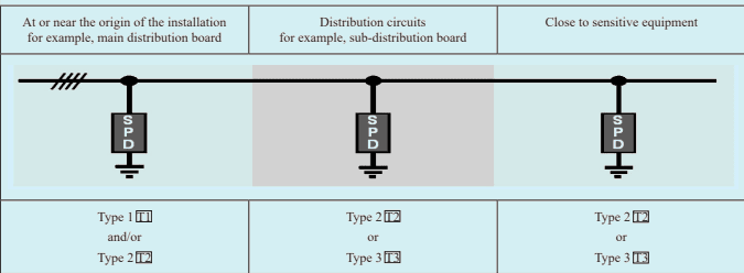
Fig. 3 Example of Installation of Type 1, Type 2 and Type 3 Spds
The presence of SPDs installed downstream of a distribution board (for example, in a socket-outlet) shall be permanently indicated (for example, by a label) in this distribution board.
Protection against transient overvoltages may be provided:
a) between live conductors and PE (common mode protection); and
b) between live conductors (differential mode protection).
NOTES
1 Connection type (CT1), primarily, provides common mode protection. If differential mode protection is also necessary, this will in most cases require additional SPDs between live conductors.
2 Connection type (CT2) provides a combination of common mode protection and differential mode protection.
Protection between live conductors and PE (including neutral to PE if there is a neutral conductor) is compulsory.
Protection between line conductors and neutral (if there is a neutral conductor) is recommended to ensure equipment protection.
Protection between line conductors (in the case of multiple phases) is optional.
Some equipment may require both common mode protection (for impulse withstand) and differential mode protection (for impulse immunity).
NOTE — For example, electronic class I equipment or class II equipment with FE-connection requires common mode as well as differential mode protection to ensure overall protection against transient overvoltages due to switching or from atmospheric origin.
| FIG. 4 CONNECTION TYPE CT1 (4+0-CONFIGURATION) FOR A THREE-PHASE SYSTEM WITH NEUTRAL | FIG. 5 CONNECTION TYPE CT1 (3+0-CONFIGURATION) FOR A THREE-PHASE SYSTEM | FIG. 6 CONNECTION TYPE CT2 (E.G. 3+1-CONFIGURATION) FOR A THREE-PHASE SYSTEM WITH NEUTRAL |
No building can be treated as complete and ready to occupy without the infrastructure of services. Out of total capital expenditure of building, share of services may go up to 40 percent, from which its value and importance can be envisaged. Under Part 8 of National Building Code (NBC) following services have been enlisted under sections:
Section 1 Lighting and natural ventilation
Section 2 Electrical and allied installation
Section 3 Air-conditioning and heating, and mechanical ventilation
Section 4 Acoustics, sound insulation and noise control
Section 5 A Lifts
5 B Escalators and moving walks
Section 6 Information and communication enabled installations
This section of Code (Part 1/Sec 15) covers electrical aspects (including electronics) required to be considered with respect to installation/construction, working/operation of building services.
NOTE — Each of these services may require statutory approval, details of which are covered in the respective sections
The standards listed in Annex A contain provisions, which through reference in this text, constitute provisions of this standard. At the time of publication, the editions indicated were valid. All standards are subject to revision, and parties to agreements based on this standard are encouraged to investigate the possibility of applying the most recent editions of the standards.
Next to geographical region, the factor influencing need and scope of building services is orientation of building. Orientation of building help utilize natural resources to provide physically and psychologically comfortable living inside the buildings by creating conditions which suitably and successfully ward off the undesirable effects of severe weather to a considerable extent by judicious use of the recommendations and knowledge of climatic factors.
IS 7662 (Part 1) gives recommendations on orientation of buildings.
From the point of view of lighting and ventilation, the following climatic factors influence orientation of the buildings and desired fenestration to optimize use of natural resources:
a) Solar radiation and temperature,
b) Relative humidity, and
c) Prevailing winds.
During the daytime, use of natural light to the possible extent shall form one of the principles of Good Lighting. It is nature’s call and conserving energy is today’s need to save and protect environment. Good visibility and other parameters are easily met with natural light source.
Illumination design of required artificial lighting, which considers various factors mentioned under 4.2 above decides selection of type, wattage and required number of light fittings. The layouts are prepared locating positions of lighting fixtures not conflicting with the sweep of fan blades. It is one of the basic requirements for design of wiring installation.
Light sources dissipating heat shall be carefully wired, located and installed so that they shall not cause hazard during their service life.
Important areas where visibility during emergency is necessary and mandatory, lighting fixture shall be suitable to sustain under such situation and shall be provided with standby source of electric supply.
a) Lighting fixtures shall be selected which have good efficacy (Lumen/watt). LED lights are giving improved efficacy day by day.
SP 30 : 2023
b) Circuits shall be so designed that portion of lighting where daylight is available can be switched off.
c) Occupancy sensors help automatic switching off lights when the particular portion is not occupied/used by persons.
d) Under green building concept lighting power density is one of parameter in deciding rating.
General ventilation involves providing a building with relatively large quantities of outside air in order to improve general environment of building. This may be achieved in one of the following ways:
a) Natural supply and natural exhaust of air,
b) Natural supply and mechanical exhaust of air,
c) Mechanical supply and natural exhaust of air, and
d) Mechanical supply and mechanical exhaust of air.
Adequate fenestration with due consideration to wind directions help avail natural resource of ventilation. Design considering natural air circulation cross ventilation, convection currents saves electrical energy cost. Renewable natural resources shall hence be explored to optimum level to conserve energy and protect environment.
For human comfort artificial ventilation is needed which is provided with various types of fans.
Ventilation is integrated in Air-conditioning system where concern is human comfort. However, forced/mechanical ventilation is needed in specific areas and purposes. It is important where dust free environment, positive pressure, smoke evacuation is needed. Reference should be made to IS 3103 and IS 3362 which cover methods of mechanical ventilation.
4.6.1 As per the design equipment requiring electrical supply shall be provided with electrical installation of required specifications and guidelines given under Section 9 of Part 1.
4.6.2 When mechanical ventilation system relates with human life safety, in emergency, electrical supply integrity must be ensured for its operation till certain predetermined time. The electrical installation and material shall be of such grade, specifications and quality.
4.6.3 In case of ducting provision of dampers shall there to restrict spread of fire.
4.2.1 When the daylight starts diminishing or there are limitations to use daylight, artificial lighting becomes inevitable. Illumination Engineering is a specialized branch which gives inputs for good lighting design.
For detailed aspects of illumination, National Lighting Code 2010 and IS 3646 (Part 1) shall be referred. Important aspects of lighting are:
a) Lux Level — A functional requirement from the point of view of visibility. (Lux=Lumen/m2). Depending on application, uniform, task oriented, average and allowable maximum and minimum lux levels are taken in to consideration while designing.
b) CRI — Colour Rendering Index, is a parameter used to measure ability of light source to reveal natural colour of object. It is measured in percentage. 100 indicates accurate, 90 indicate good colour rendering.
c) CCT — Correlated colour temperature measured in Kelvin helps to indicate colour appearance, for example, cool white 5 000 K, yellowish warm-light 3 000 K which are selected to create required ambiance.
d) Glare — It is measured as Glare Index which relates to the discomfort/difficulty of seeing.
4.2.2 Following applications decide design parameters and selection of light source:
a) Indoor — Functional requirement:
Dwellings,
Commercial,
Industrial,
Educational,
Auditoriums/theaters, and
Exhibition centers, art galleries, museums.
Sports
b) Indoor — Aesthetic:
Mood,
Ambiance, or
Spot
c) Outdoor — Functional requirement
Streets/paths, or
Garden.
d) Outdoor/external — Aesthetic
Façade, or
Ceremonial.
Electrical Installation is a prime utility service to become any building functional. Many other building services also depend on electrical supply for its operation. It has some architectural and civil work requirements. Reference
is made to all other sections from different parts of this code and especially Section 9 of Part 1, where various aspects have been elaborated in detail.
Design shall be based on basic principles of:
a) Safety,
b) Quality, or
c) Integrity and continuity.
Safety is of prime importance and statutory requirement. Supply quality and continuity are also basic needs of building service. Prolonged failure of electrical supply may bring life to standstill especially in high-rise buildings. Standby supply source of required capacity, shall therefore be designed, installed and maintained. Depending on capacity and time duration it may be battery based or a Generating set.
Electrical supply and installation, apart from its need and use, carries high risk of fire endangering safety of life and property. Stringent norms are required to be followed. Improper installation, use, handling, operation and maintenance may lead to serious hazards. Reference is made to Section 10 to 13 and Section 22 from Part 1 of this code.
Supply integrity under emergency conditions and evacuation operation is most important requirement. Electrical installation supplying critical load, shall be of such material, which withstands under fire conditions till desired time of 2 or more hours anticipated for evacuation operation. It shall also be backed up with required capacity of standby supply arrangement. Emergency lights shall be tested once in 30 days for 30 s and once in a year for 1.5 h. It is recommended that records for the same shall be maintained.
Air conditioning is process of treating air to:
a) Cool/heat to regulate temperature;
b) Humidify/dehumidify to regulate moisture;
c) Filter to reduce contaminants;
d) Ventilate to regulate fresh air requirement, air quality and odour; and
e) Circulate to regulate air motion-no drafts, no suffocation.
Its application can be divided in to two categories, comfort air-conditioning and process air-conditioning. Comfort air-conditioning relates to human comfort. Process air conditioning is to provide above controlled parameters of air suitable for a process, for example, preservation of food items, controlled temperature may be 4°C or -20°C; for operation theatres cleanliness of air shall be of prime importance; and textile mill needs higher humidity.
NOTE — Under ‘air-conditioning’, heating and ventilation form a part of the system and are referred as Heating, Ventilation, and Air-Conditioning (HVAC).
6.2.1 For the design of the system studying existing situation and set target of desired level of Indoor Air Quality (IAQ) for required application, in possible climatic condition all around the year is of prime importance. IAQ if not monitored and maintained properly, may lead to discomfort, sickness loss of efficiency or loss of product under process air-conditioning.
6.2.2 In design of the system assessment of following factors is important:
a) Climatological data;
b) Outdoor air quality and properties of air;
c) Psychometry;
SP 30 : 2023
d) Orientation, of building;
e) Use, occupancy
f) Heat load/cooling load; and
g) Air distribution.
Depending on requirement, worked out on area, use and Tonnage of Refrigeration (TR) system may be:
a) Unitized, window, split for small areas;
b) Packaged, VRF for medium areas; and
c) Central; for large areas.
Window, split units are factory assembled and are generally available up to 3 TR capacity. Split types which are more popular due to very low noise levels comprises indoor and outdoor unit connected with refrigerant piping. It requires additional condensate piping. It shall be noted that; like window type unit, there is no provision of fresh air intake for split type units.
Packaged/VRF systems are generally available up to 15/20 TR or more capacity depending on manufacturer’s design. These systems require arrangements of refrigerant piping, condensate piping and ducting.
Central Air conditioning systems are usually used for large areas, TR may extend to required capacity. System comprises chillers, refrigerant/chilled water and condenser water pumps and piping, Air Handling Units (AHU), Fan Coil Units (FCU)/Cassette units, cooling tower. Location of plant room comprising chillers is usually away from area to be air-conditioned. AHUs are closer and FCUs within conditioned space. Cooling tower is installed in open air preferably near chillers, to restrict length of condenser water piping.
Proper selection and design of system is a job of air conditioning expert where type of use, load conditions, quality, efficiency, economy in installation and running cost are important factors.
Two main aspects are:
a) required electrical installation, and
b) electrical consumption.
Electrical Installation shall suite the manufacturer’s requirements.
On broad basis electrical load per TR varies between 1 to 1.5 kW. Under advanced technologies, it may reduce further. Nature of load mainly being inductive involving in-rush of current, shall be considered for selecting size of cable and protections.
With the increased use of inverters and variable frequency drives harmonic distortion may occur if adequate filters are not designed and provided. Manufacturer’s specifications shall be checked for provision of inbuilt filters and necessary additional provision shall be made checking actual requirements depending on site tests.
Separate circuit with C type MCB of required ampere capacity generally 16/20/25 A or as per manufacturer’s recommendation, depending on TR rating shall be provided for window/split type units. Though most of the units are controlled with remote control, and location of indoor unit sometimes inaccessible, a controlling switch shall be available in accessible position with a power outlet near indoor unit. Generally wiring between indoor unit and outdoor unit is done by the service provider/installing agency. However, efficient earthing shall be ensured at the point of supply outlet.
Electrical Supply point with adequate size and type cable, earthing and controlling switchgears shall be made available as per manufacturer’s requirement. Controlling switchgear shall be provided near the individual
equipment in accessible position. Rated current capacities shall be adequate. Many times, such locations are in open. Appropriate ingress protection from external influences shall be provided to guard from adverse climatic effects and an arrangement for ease and safety to operating/maintaining personnel.
As per equipment layout of AC system comprising compressors/chillers, chilled water, condenser water pumps, cooling tower, AHUs, FCUs etc., electrical supply arrangement shall be done in consultation with the concerned agency. Cable sizes, types, routes, controlling switchgears and protections shall be as per the guidelines given under Part 1/Section 9 and related clauses from Section 10 to 13 of this part of this code.
Where conduits are used for carrying insulated electrical conductors and when such conduits pass from a non-air-conditioned area into an air-conditioned area or into a fan chamber of duct, a junction box shall be installed or other means shall be adopted to break the continuity of such conduit at the point of entry or just outside, and the conduit should be sealed round the conductors to prevent air being carried from one area into the other through the conduit. This will prevent leakage and inefficiency as well as avoid the risk of condensation of moisture inside the conduits.
With the trend of horizontal and vertical expanse of buildings; lifts and escalators at places like air ports where there is huge horizontal spread are used increasingly. Horizontal walks are becoming inherent part of the building services. These services require architectural planning and civil work provisions along with electrical work. These points therefore come within the scope of primary planning.
7.2.1 Design of lifts is done on the basis of anticipated/available/assessed data of human traffic at peak time, number of floors and vertical travel, round trip time and application. These factors decide persons carrying capacity of lift, number of lifts (weight considered per person is 68 kg) and speed. For safety aspects, design requirements, installation, operation, maintenance and inspection requirements IS 14665 series shall be referred.
Depending on type, construction of lift requires shaft of RCC construction. As per designed speed and capacity of number of passengers, it requires pit of required depth (below lowermost floor level), overhead (vertical clearance from topmost floor level to bottom of machine room slab), a machine room on top of slab. In case of Machine Room Less (MRL) lift, there is no need of machine room and in case of Capsule Lift, requirement and specifications of shaft may vary or can be eliminated. Door openings (width × height) and landing sill shall be as per IS 17900 (Part 1). All details shall be taken from manufacturer in advance at planning stage. Adequate provisions as per norms shall be made in respect of ventilation and positive pressure.
Provision of fire lift shall be as per the requirements given in National Building Code of India. This lift and related structure shall have rated fire withstand rating and shall perform and sustain desired operation and function during fire/emergency.
Need and provision of escalator is seen usually at public places where service to the quantum of public is to be given. Hence, the installations are seen in cinemas, malls, railway stations, offices with higher occupancy, etc. Civil work infrastructure needs to be provided as per manufacturer’s requirements. For safety aspects, design requirements, installation, operation, maintenance and inspection requirements, IS 4591 series shall be referred.
Places where walking distance (horizontal) within building is more and time taking, provision of walkways is done. It is usually seen at airports.
7.5.1 Reference is drawn to Lift Act and Rules made thereunder by respective state governments and IS 14665 series. Manufacturer shall coordinate with architect, civil construction agency and electrical contractor to see all structural, electrical requirements are met and shall construct the lift, escalator, walk-ways complying statutory requirements, and standards, norms.
7.5.2 Work related to all safeties, control cabling, telephone, alarm, automatic rescue device and battery backup and electrical cabling after point of supply to machine, lift car, protections comes in the purview of lift manufacturer. He shall adhere to all norms.
7.5.3 Testing, commissioning, arranging inspection and permission from concerned authority to operate lift is manufacturer’s responsibility. Manufacturer shall handover lift with all documentation, guarantees/warranties, maintenance schedule to the owner. He shall provide information in respect of obligations of owner especially in respect of maintenance of lifts.
The requirements for main switches and cabling with reference to relevant regulations may be adhered to. The manufacturer should specify, on a schedule, particulars of full load current, starting current, maximum permissible voltage drop, size of switches and other details to suit requirements. For multiple lifts, a diversity factor may be used to determine the cable size and should be stated by the lift manufacturer.
7.6.2.1 All electrical supply lines and apparatus forming part of point of supply to be provided to manufacturer for his further work in connection with the lift/escalator/moving walks installation shall be so constructed and shall be so installed, protected, worked and maintained as per relevant sections of this code.
7.6.2.2 All metal casings or metallic coverings containing or protecting any electric supply lines of apparatus shall be efficiently earthed. Earthing system shall conform to provisions of IS 3043 and CEA (Measures Relating to Safety and Electric Supply) Regulations, 2010.
7.6.2.3 All cables and other wiring in connection with the lift installation shall be as per relevant standard.
a) Power Supply Mains — The lift sub-circuit from the intake room should be separate from other building service. The separation of cable route and source (circuit breaker/MCCB directly in the respective circuit) shall be made in such a way that failure of the building service feeder does not affect the feeder for the lift. Each lift should be capable of being isolated from the mains supply.
b) For banks of interconnected lifts, a separate sub-circuit is required for the common supervisory system, in order that any car may be shut down without isolating the supervisory control of the remainder.
c) Lighting — Machine rooms and all other rooms containing lift equipment should be provided with adequate illumination and with a switch fixed adjacent to the entrance. At least one socket outlet and light point, should be provided at each floor level in the lift shaft including pit.
d) 3 phase power supply cable for machine and 1 phase power supply cable for lighting shall be routed through lift shaft and first terminated in machine room, (when provision of machine is there). 1 phase supply cable shall again be re-routed through shaft for lighting and power supply outlet. No cables, which are not part of lift installation, shall run in the lift well. The lift cables shall run in respective lift wells. Wiring in machine room shall run in rigid metallic trunking. The trunking in machine room floor shall be flushed with the finished floor.
e) Residual current devices shall be of appropriate type and sensitivity. It shall:
have 10 times the maximum leakage current (300 mA maximum) as tripping current and be suitable for frequency converters with a 3-phase supply.
Intercom system is important private internal communication system forming one of the building services. It may integrate with external public network.
Requirements shall be assessed at planning stage, with the exchange of information within concerned users and architect/consultant. Design and layouts of equipment showing locations and routes of cabling shall be planned, in advance. It shall form a coordinated activity with construction and other building services.
Main components of the system are:
a) Telephone instrument,
b) Patch cord,
c) Socket/registered jack (RJ series),
d) MDF/junction boxes of required sizes,
e) Krone modules,
f) EPABX exchange,
g) Power supply, and
h) Telephone cables 2-4 pairs, jelly filled armoured/un-armoured cable 10 to 100 pairs.
Electronic private branch exchanges (EPABX) may be connected to the public exchanges through exchange lines or limited to internal communication. EPABX permit internal communication between the extensions of a system and external communication, for approved branch systems. EPABX is specified with number of incoming lines and outgoing lines of internal communication. For example, 3/8 means exchange having facility to connect three incoming lines from other private or public network and 8 lines of internal network.
Generally, the inter-floor/inter-building backbone cabling is included in the scope of main building design. The backbone cabling should accommodate analog voice signal alone or analog and data signals simultaneously, as the case may be. It is the speed of data transmission and bandwidth, which matter most in the design of the communication backbone.
9.4.1 The exact requirement of the subscribers shall be assessed before drawing out the specification of the EPABX system. This means that information on number of subscribers in the building, distribution of the phones in the floors and other areas, nature of traffic etc. are to be collected.
9.4.2 The initial and final requirements of the installations should be ascertained as accurately as possible by prior consultations. Plans shall show:
a) details of the installations proposed;
b) the accommodation and location of the EPABX console, monitor, etc; and
c) the ducts and cable routing required for wiring.
9.5.1 The basic architecture and performance requirements of the modern day communication system is microprocessor-based pulse code modulated (PCM)/Time Division Multiplexing (TDM) technology.
9.5.2 The environmental conditions for the EPABX should preferably be controlled so that the room air temperature is maintained between 1 0 ° C and 4 0 ° C and relative humidity between 50 percent and 95 percent.
9.5.3 Integrated Services Digital Network (ISDN) is commonly required for commercial buildings since it is possible to handle simultaneous calls of different types namely voice, data and images transfer (tele and video
conferencing) without any loss of data, at a minimum speed of 64 kbps, which can be increased further depending on requirement. EPABX system shall be capable of interfacing with other EPABX system through appropriate protocol.
In EPABX system the individual call stations are connected, each by a twisted pair of wires to the automatic exchange (see Fig. 1). This is also the termination for the exchange lines.
There are various features available with the present day EPABX with introduction of concerned cards. Features to be incorporated shall be decided depending on functional requirement. Some of the most common features included are abbreviated dialing, recorded announcement system, last number redial, executive override, multi-party conference, call forwarding, direct inward dialing (DID), automatic alarm make-up call, STD barring, group hunting, networking facility.
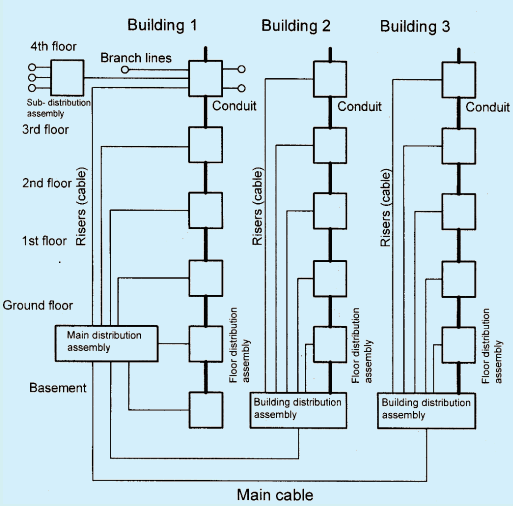
Fig. 1 Example of the Arrangement of a Basic EPABX System in Large Building
229
Depending on the size and type of installation, the telephone system requires for its operation a d.c. power supply of 24 V or 48 V, which is obtained from the power mains through a rectifier. The rectifiers provided with closedloop control and for small and medium sized systems, are accommodated in the exchange housing. For large systems, rectifiers (controlled) are supplied in separate cabinets.
Standby batteries can be provided as an adjunct to the rectifier. These are necessary for important installations such as police stations, fire stations, etc., to cover possible main supply failures.
9.7.1 The switching equipment for the telephone systems and small EPABX’s takes up little room. Apart from the telephones, only relatively small wall-mounted junction boxes or exchange units are required. The exchanges, furthermore, produce little or no noise, so that they can be accommodated in an office if desired.
9.7.2 For large systems, a separate room should be provided for the exchange equipment, and similarly, for the answering panel. Space should be allowed in planning for additional cabinets or racks, exchange equipment platforms etc. that may be necessitated by future enlargement of the systems. The size of the battery room depends upon the type of power supply equipment used.
9.8.1.1 For wiring within buildings, wire is mainly installed in embedded PVC conduit, or wiring cables with conductors of 0.6 mm or 0.8 mm diameter for surface wiring.
9.8.1.2 For cabling, it is important to maintain a separation of at least 10 mm between the communications wiring and power cables.
9.8.1.3 If conductors belonging to different communications systems run together, for example, telephone wires and loudspeaker wires, or heavily loaded slave clock circuits, there is a risk of mutual interference between them. In such cases it is advisable to use screened cables.
9.8.1.4 In communication cables, the cores are twisted together either in pairs or in star quad formation. For speech transmission to avoid crosstalk either a twisted pair or, in the case of the star quad a pair of opposite cores should be used.
9.8.2.1 In the course of constructing the shell of the building the appropriate channels and ducts should be formed in the masonry and lead-through apertures provided in walls, ceilings, joists and pillars. Suitable accommodation should be provided for the distribution boards in large communications system (for example, recesses, shafts etc.).
9.8.2.2 For riser cables, the ducts and ceiling apertures for the riser cables should be sufficiently large to permit the later addition of cables or PVC conduits without great expense.
PVC conduit can be used for the individual sections of conduit networks in residential buildings for the riser conduit from floor to floor, horizontal branches in the floors up to the distribution boxes in the apartments, and between the distribution boxes in the apartments and the flush-type junction boxes.
In addition, at least one extra conduit should be provided from one floor distribution board to the next.
In residential buildings, a concealed wiring arrangement is most conveniently and economically installed in an adequately dimensioned conduit network. It has been found satisfactory to provide riser conduits or cable ducts and horizontal branch conduits to the apartments, with distribution boxes at the junctions. With a concealed installation of this kind, it is possible at any time to alter the wiring or add to it without inconvenience to the occupier.
In office buildings, manufacturing plants, department stores etc. particular importance is attached to flexible arrangement and utilization of the accommodation. To this end, communication wiring can be run in underfloor trunking systems or window-sealed trunking rather than on the walls.
Computer networking is an inherent part of building service in most of the offices, commercial and industrial establishments. Networking is an independent and specialized subject. Speed of development, advancement and upgradations in this field are very fast. With the increased demand of transmission speed (band width), new products are replacing existing products at a fast pace and rendering them obsolete. The scope under this section do not cover technology, but consider infrastructural provisions to be made in planning, and installation, basically limited to wired networks and its aspects related to building and other building services.
This branch of technology is developing quickly and improved versions are replacing the old ones. A note shall be taken that components mentioned in this section may become obsolete with the availability of new ones in coming times.
In networking, different topologies exist which is decided by network designer. Physical network correlates with actual setup of various components. Locations of these components and cabling routes is part of planning, especially when cabling is concealed type, underfloor. Layouts shall be finalized jointly in consultation with network designer. To avoid conflicts between different service providers it shall be mutually agreed by Architect/ MEP consultant and other service providers. Main components of networking are:
a) Information outlets,
b) Network switch(s),
c) Transceiver,
d) Router(s),
e) Patch panels,
f) LIU with adapter pigtails etc.,
g) Rack,
h) Patch cords, cross cords,
j) Cables – STP/UTP category (Cat6, Cat7),
k) Optical fibre, and
231
l) Connectors.
Selection of cables shall be as per recommendations of system designer. Cat 5, Cat 5e cables are becoming obsolete with the advancement in technologies. There is continued improvement in capacity of cable to support bandwidth and handle data transmission speed. At present, Cat 6 and Cat 6A cables are widely used which can transmit 1 GBps over 100 m length and Cat7 can transmit 10 GBps over 100m length. To be on safer side, the length shall not exceed 90m. Unshielded Twisted Pair (UTP) cables are most widely used. However, in the locations where electromagnetic interferences are likely to be predominant or where power cables are in close vicinity, Shielded Twisted Pair (STP) shall be preferred. To overcome restriction of length, OFC shall be used. Single mode Fibre optic cables do not have limitation of length. Multimode OFC can support higher speed but may have limitation at length above 500 m.
Depending on location, and number of cables, conduits, trunking and raceways of adequate cross section shall be selected. Clearances from other services as recommended by system designer shall be maintained. Depending on circumstances, provision of raised floors may be necessary in certain areas to facilitate routing of cables. While installing, restriction of bending radii of cables shall be observed.
In large setups such as data centers, very large number of cables are required to be handled. If cabling is not planned and installed as per protocols, it may lead to mess, create difficulties in maintaining and augmenting. It will also disturb aesthetics. To resolve the issue, preference shall be given to structured cabling over point to point connections. It helps maintain neatness, facilitates movement/shifting, addition and/or modification in existing network in a very convenient and easy way. It saves time as tracing is easier with lesses chances of human error.
Terminations are done with a connector. This device terminates a segment of cabling or provides a point of entry for networking devices such as computers, hubs, and routers. Connectors can be distinguished according to their physical appearance and mating properties, such as jacks and plugs (male connectors) or sockets and ports (female connectors). There are many types of connectors. Most commonly used connectors in cable networking are RJ 45 (RJ- Registered Jack).
Installation shall be tested for desired performance. Network performance test shall be carried out to quantitatively or qualitatively measure the performance of a computer network. A network performance test primarily tests the uplink and downlink speed of a network. It defines how quick and responsive a network is to user/data communication. It is done by uploading and downloading a data object from the network and measuring both upload and download speeds, throughput, successful message delivery rate and more.
Clearance of 200mm shall be maintained between network cables and electric power cables, if there is no physical segregation. Crossings shall be at right angle.
LAN equipment is sensitive and vulnerable to voltage fluctuations/surges. SPDs shall be installed on the circuits providing electrical supply equipment. Distribution of Electric Supply to all computer networking shall be through UPS with required backup depending on situation. Electrical distribution and layouts shall be so designed that circuits and routes supplying computer system equipment will be distinct from other services.
Earthing system is an important aspect of network reliability. It shall be efficient. There shall not be difference in ground potential between supply sources to different equipment, within same network. Earthing, inefficient to dissipate surge properly to earth, may lead to electrical noise, faulty data signals, dropped packets, thus decreasing throughput and overall efficiency of network in data cables in the system. It has been diagnosed that many times, cause of damage to network equipment, such as switches, routers, storage devices, etc., is improper earthing. All
equipment in the rack shall be properly earthed with paint piercing washers, bonding cords/jumpers and nut-bolts to connect body of equipment to frame of rack and rack to, common bonding earthing bus. High purity copper backbone bus and other spares used for earthing system in network will mitigate risk of failures.
233
Building Management System (BMS), a computer-based automation tool to control/monitor various building services, generally needed in projects having with medium to large expanse. It may be possible to control, operate,
SP 30 : 2023
monitor building services through a central control station integrating various services as given below:
a) Illumination
b) HVAC
c) Security systems
Access control
CCTV
Alarm
Motion detectors
PA system
d) Fire alarm
e) Fire fighting
f) Elevators
12.2.1 At planning stage, architect in consultation with owner/stake holders shall enlist various services to be incorporated in the building. Further, scope of BMS – single or multi-task shall be agreed upon.
12.2.2 BMS consists of hardware and software programme (usually, configured in a hierarchical manner, can be proprietary or IP based with open standards). Design and integration of different building services shall consider following aspect which are achievable through limited human resources, eliminating possibilities of human error.
Effective monitoring and targeting of electric supply quality and continuity within internal distribution. Optimising energy consumption with the use of various types of sensors, PLCs, actuators, to allow automatic setback override during unoccupied periods as well as adaptive occupancy scheduling.
Lighting controls programmed to turn on/off, dim by integrating occupancy/motion sensors, photo sensors, timers, on time of day/work time scheduling in system, to reduce unnecessary artificial lighting via motion sensors and as well as by controlling daylight harvesting louvers.
Climate control by monitoring HVAC system to avoid waste, suit precise requirements Indoor Air Quality (IAQ), Demand controlled Ventilation for human comfort and health. For example, controlling mix of fresh air with returned air, by placing sensors in room/duct, monitoring air dampers, chilled/hot water line valves in Constant Air Volume (CAV) or VFDs in Variable Air Volume (VAV) system by adjusting CFM.
Follow and monitor maintenance schedules for improved equipment/plant reliability, minimal breakdowns/ outages and increased service life.
Save water and energy by monitoring water storage through pumping, rainwater harvesting, sewage treatment plant (STP), Water treatment plant, etc.
In case of fire, isolating electrical supply other than involving emergency services, automated operation of fire-fighting system by integrating fire alarm, CCTV system. Automated operations in HVAC system like closing of dampers in the ventilation system to control smoke spreading, shut down air handlers, start smoke evacuation fans, and send all the elevators to the ground floor and park them to prevent people from using them.
a) Work station(s);
b) Computer/server;
c) Back-up arrangements;
d) Control units;
e) Various types sensors;
f) Actuators;
g) Cable network, LAN;
h) Required software; and
j) Internet connection.
BMS system benefits in many ways and is recommended in major projects. The main points are given below:
a) Data can be consolidated onto a single system, which helps reporting, managing information, decisionmaking and record keeping.
b) Comprehensive reporting with functionality for customizable reports delivers greater transparency into system history and promotes compliance.
c) Integrating and managing various building services functionality of which may be interdependent.
d) Control can be achieved from single workstation which allows facility-wide insight and control for better performance.
e) Efficient resource deployment can result in reduced operational costs, empowering operators, simplifying training and decreasing false alarms.
f) Real-time view into facility operations and deep trend analysis provide data-driven insight to optimize your energy management strategies and minimize operational costs, targeting energy efficiency.
g) BMS can help support growth and expansion of the system in the future.
h) With help of information from BMS it is easy to observe maintenance schedules with optimum use of maintenance staff. It helps predictive maintenance and avoid breakdowns.
j) Strategic mobile or desktop control, exceptional alarm management and integrated security solutions helps to see the big picture, helping to speed up response time and mitigate risks for the property, people and business.
BMS deals with energy demand management (EDM). It controls waste and reduces electrical energy consumption. It helps to improve and maintain quality of supply and supports energy efficiency.
Network topology, bus, cables and their type – twisted, shielded, screened/CAT 6/fibre optic and core material of high purity copper shall be as per recommendation of system designer. Length shall be restricted in accordance with cross section, maximum allowable drop to restrict data loss and speed. Separate conduits shall be used with adequate spacing between cabling of other services.
Electrical Supply to control room shall be through UPS with adequate backup time to suite specific requirement. Use of Fire Survival cables shall be ensured from source of main supply to UPS and for further, distribution to power outlets for related equipment.
Following points shall be considered as precautionary measures:
a) Administrative control shall be well defined with responsibilities;
b) Considering risk of hacking, necessary measures shall be taken to prevent it;
SP 30 : 2023
c) Data shall be backed up. Access rights shall be kept as record;
d) System shall be maintained, critical items shall be identified and checked periodically; and
e) Information/cyber security measures shall be adhered to.
Surveillance and security systems, as the name suggests, are designed to keep an eye and cover blind spots in building and premises, monitoring authentication and vigil on persons entering and exiting, etc. These systems primarily consist of security cameras and automated access control mechanism.
Close Circuit Television (CCTV) has many fold applications. It is important tool of surveillance and can be linked with security system of building like access control, employees monitoring, life safety and evacuation under emergency condition, and can be integrated with BMS for other various aspects. With computer controlled analytics and identification software, it is possible to analyse specific object/identity/action from the video streaming or for forensic application. Depending on need, retention, storage and preservation of recorded data is possible. The preservation may be set for pre-set time period, and quality from which capacity of storage device is decided. CCTV system can be wired or wireless. Scope considered under this section is not going into the details of technology but the factors to be considered in respect of layouts, installation of CCTV system and coordination with other services including electrical aspect.
Design and selection of cameras and equipment comes in purview of system designer/provider. The locations of cameras, equipment and if necessary, control room, shall be marked on drawing, in consultation with architect and other service providers so that conflicts do not arise during installation, functioning is not disturbed and maintenance in future can be attended with ease.
Depending on scope/expanse, system may comprise following components for which location, routes need to be decided and marked on drawings:
a) IP Based CCTV IP Based Network Camera CAT6 Cables PoE Network Switch Network Video Recorder (NVR) with Surveillance HDD/NAS system/Video Servers etc. LED Monitors/Display Network Rack RJ 45 Connectors Optical Fiber Cable (OFC) Transceiver LIU with adaptor pigtails etc. b) Analog CCTV CCTV Camera 3+1/4+1 CCTV Cables DVR (Digital Video Recorder with Surveillance HDD LED Monitors/Display DVR Rack BNC Connectors and Power Connectors Power Supply
Cabling shall be done by maintaining required clearances from other services and shall run through independent enclosures. Conduits of distinct colour coding may be used for identification. In case of electrical power cables, distance 200 mm shall be maintained, if there is no physical segregation.
Supply for CCTV system shall be provided through independent circuit. All necessary measures may be considered to maintain supply quality and integrity. Provision of UPS with adequate backup shall be done as a security measure so that recording doesn’t get interrupted by malicious act. Electrical supply panels of important nature may be kept under CCTV surveillance.
Access Control System makes it possible to control the entry and exit of person in building. It can identify, authenticate, record timings of entry and exit and hence, presence of person in the building. Premises requiring security use different types of access control systems with varied levels of security depending on type of use – residential, commercial, institutional, or places of high security. The data available may be of use for security, administrative purpose, crime investigation, etc.
11.3.2.1 Access point may be decided by building administration/management, security personnel depending on size, expanse and level of security. Access control may comprise biometric, RFID, door controllers with electromagnetic locks and card readers, integrated with CCTV for identification of person, intrusion detection etc. A wired security system is connected by low-voltage wires and a wireless security system may employ tiny radio transmitters which transmits signals to the central control unit. Uninterrupted power supply is an important requirement for these systems.
While designing, most important part of access control system is its operation during emergency, like fire; where fast evacuation is of prime importance. Under the circumstances if the egress is hindered by locked doors, it proves to be fatal. There are many ways and methods through which the behavior of Access control system under fire conditions can be designed. Centralized/individual door access control, power supply to magnetic locks, provision of pull stations near the doors, location of control panel, power supply, access to these points have important role in this regard.
The door access control reader and the electric lock may be wired to the fire alarm in a number of different ways. A system may be designed to drop power to the electric lock or use an IP device that drops power using the network connection or add a power control box that drops power when the fire alarm system detects a fire.
NOTE — It is a prime liability of concerned owners/administrators of building and system provider to make and maintain all necessary provisions for emergency conditions.
The system shall be provided with Uninterrupted Power Supply with backup for assessed or mandated time period but not less than 2 h. The power circuits shall be independently controlled with FS grade cables/wires. The wiring used in access control system shall observe all fire related parameters in respect of selection of material and installation method to maintain supply integrity for assessed time period of not less than 2 h.
NOTE — It is important to note that occupants shall be trained to handle Access Control system installed at entrance, and exit doors and shall form a apart of drill.
Fire-fighting and alarm system is most important building service related to life safety of the occupants in the building This service comes under purview of legal provisions under the Act and Rules notified by respective State Governments. Table 7 under Part 4 of National Building Code categorizes various types of buildings, depending on occupancy and height and prescribes safety provisions for fire prevention and life safety. Provisions of part 4 from NBC has been adopted by most of the states and UTs for mandatory implementation. For details, Part 4 of National Building Code of India 2016 may be referred. The section provides an overview of the systems installed to detect the fire, prevent from spreading and save the lives under fire situation and electrical aspects related to these systems. Fire alarm system and fire-fighting system are interdependent but are based on different engineering aspects.
13.2.1 The fire alarm includes fire detection and alarm notification. It helps to detect fire at an early stage, send alerts so that appropriate action can be taken to help evacuation of occupants, calling fire-fighting tender, initiating operation of installed fire-fighting system and hence control spread of fire. The integrated PA system help occupants guide to escape routes and mitigate situation of panic. IS 2189 prescribes selection, installation and maintenance of automatic fire detection and alarm system.
13.2.2.1 The system mainly comprises of following components:
a) Detectors — Smoke, heat, beam, multi sensor, flame, spark, ionization, air aspiration, etc.;
b) Hooters;
c) Manual call points;
d) Fire alarm panels — Local/repeater/main;
e) Hooter cum strobes; and
f) Appropriate cable.
13.2.2.2 Design of fire alarm system shall be done by accredited or authorized agency or person. Selection of type of system – addressable and non-addressable, design and layout (number, location, route of cables) shall comply guideline given under IS 2189 which prescribes selection, installation and maintenance of automatic fire detection and alarm system and Part 4 of National Building Code of India 2016.
13.2.2.3 Circuits controlled and powered by fire alarm system may include circuits for control of building systems safety functions like elevator control, shut down, door release, smoke doors, fire doors and damper control, mechanical ventilation/pressurization system. This helps to monitor the fire prevention and life safety operations.
Cables shall be of copper conductor with minimum cross-section area of 1.5 mm2. Depending on requirements, the selection of cable shall be of grade FRLSH/HFFR/FS (Circuit Integrity) complying with the requirements of IS 7098 (Part 1)/IS 17048/IS 17505 (Part 1).
Supply integrity for required time duration shall be assessed based on the evacuation period or as recommended by Chief fire officer. These cables shall be easily identifiable on common treys, raceways etc. The grade of insulation shall not be less than that of other cables running along. The routes of cables shall be planned to avoid adverse impact under emergency situations.
The equipment and wiring of the fire alarm system shall be independent of any other equipment or wiring and shall preferably be spaced at least 5 cm away from each other. Depending on requirement of mechanical protection and their placement, fire alarm cables may be armored and shielded. Unshielded cables for fire alarm systems shall be used in metallic conduits.
Electrical supply for fire alarm system shall have 100 percent standby arrangement. There shall be a provision of secondary battery continuously trickle/float charged from ac mains, with facilities for automatic recharging in 8 h sufficiently to supply the maximum alarm load at an adequate voltage for at least 2 h. The capacity of battery shall be such that it is capable of maintaining the maximum alarm load on the system at an adequate voltage for at least 1 h plus the standing load or losses for at least 48 h. Suitable overload protective devices shall be provided to prevent discharging of the batteries through the charging equipment.
Fire-fighting system comprises fire extinguishers of various types, water-based system with hydrants, sprinklers, etc. The choice of fire-fighting equipment and their installation details shall be governed by the requirements specified in Part 4 of National Building Code of India 2016 and statutory provisions adopted by local bodies.
13.3.2.1 Depending on rules and regulations, the design and drawings of system showing details of locations of fire-fighting pump room, equipment, routes of piping, storage water tank and pump capacity, type of system, dry, wet risers, down comers, sprinklers shall be approved by Chief fire officer/concerned authority at an early stage as aftermath corrections are difficult to incoporate. Type and capacity of pumps is based on number of hydrants, coverage area, minimum pressure at farthest point, head losses, flow rate of pump (lpm) and prime mover rating of pump(kW). There shall be standby arrangement, may be of diesel engine driven pump, or gen-set to run electrical motor driven pump, in case of power failure.
13.3.2.2 The components of the water based fire-fighting system should be selected in a way such that:
a) The system shall be avaialble with water at the required pressure at all times. Pumps and pressuring systems (for example, jockey pumps, hydro-pneumatic tanks, riding tank, etc) shall be selected accordingly.
b) The capacity of the system shall be such that water can be sprayed on the largest burning object (for example, transformer or oil tank) or the largest contained zone on fire (e.g., warehouse with goods or a library hall so that the fire is confined within the walls of the enclosed space) for a sufficient time to completely extinguish the fire.
c) The piping network shall be so designed that at the pressure is maintained at the farthest end of the pipe network. Also, the flow of water required at every outlet is maintained.
d) Equipment should be so chosen that nuisance operation is avoided.
e) Equipment shall be so chosen that they operate reliably and reliability should be close to 100 percent.
f) Redundancy should be provided to ensure that the system availability is close to 100 percent even in the contingency of loss of electrical power supply required to drive the pumps.
Alternate fire extinguishing systems like clean gas flooding system or foam spray system, if used, should also meet the reliability and availability factor of close to 100 percent.
All systems used should be fail-safe in nature.
Sufficient power shall be available for a fire fighting system and the power source shall be entirely independent of all other equipment in the premises and shall not be interrupted at any time by the main switch controlling supply to the building. An indicator lamp shall continuously glow in a prominent position to indicate status of power in the substation and in the fire-pump room.
| IS No. | Title |
|---|---|
| 1881 : 1998 | Code of practice for indoor installation of public address systems (first revision) |
| 1882 : 1993 | Outdoor installation of public address system — Code of practice (first revision) |
| 2189 : 2008 | Selection, installation and maintenance of automatic fire detection and alarm system — Code of practice (fourth revision) |
| 3103 : 1975 | Code of practice for industrial ventilation (first revision) |
| 3043 : 2018 | Code of practice for earthing (second revision) |
| 3362 : 1977 | Code of practice for natural ventilation of residential buildings (first revision) |
| 3646 (Part 1): 1992 | Code of practice for interior illumination — Part 1 General requirements and recommendations for welding interiors (first revision) |
| 4591 : 1968 | Code of practice for installation and maintenance of escalators |
| 7098 (Part 1) : 1988 | Specification for crosslinked polyethylene insulated PVC sheathed cables — Part 1 For working voltages up to and including 1 100 volts (first revision) |
| 7662 (Part 1) : 1974 | Recommendations for orientation of buildings – Part 1 Non-industrial buildings |
| 17048 : 2018 | Halogen free flame retardant HFFR cables for working voltages up to and including 1 100 Volts — Specification |
| 17505 (Part 1) : 2021 | Specification for Thermosetting Insulated Fire Survival Cables for Fixed Installation having Low Emission of Smoke and Corrosive Gases when Affected by Fire for Working Voltages upto and including 1 100V |
| 14665 series | Electric traction lifts |
| 17900 (Part 1) : 2022 | Lifts for the transport of persons and goods — Part 1 Safety rules |
| SP 7: 2016 | National Building Code of India |
| SP 72 : 2010 | National Lighting Code |
Several Indian Standards exist, which cover details of selection, installation, and maintenance of electric power equipment. This Part 1/Section 16 of the Code is formulated in such a manner as to bring out only the essential criteria for selection of equipment, and users of the Code are recommended to make reference to individual product codes for detailed guidelines.
This Section of the Code (Part 1/Sec 16) covers general criteria for selection of equipment.
NOTE — This Part 1/Sec 16 shall be read in conjunction with the Indian Standard/Codes on individual equipment.
Every item of electrical equipment used in the installation shall conform to the relevant Indian Standards, wherever available.
Every item of electrical equipment selected shall have suitable characteristics appropriate to the values and conditions on which the design of the electrical installation (Part 1/Sec 9) is based and shall, in particular, fulfil the requirements given at 2.2.1 to 2.2.4.
Electrical equipment shall be suitable with respect to the maximum steady voltage (rms value for a.c.) likely to be applied, as well as over-voltages likely to occur.
NOTE — For certain equipment, it may be necessary to take account of the lowest voltage likely to occur.
All electrical equipment shall be selected with respect to the maximum steady-state current (rms value for a.c.) which it has to carry in normal service, and with respect to the current likely to be carried in abnormal conditions and the period (for example, operating time of protective devices, if any) during which it may be expected to flow.
If frequency has an influence on the characteristics of electrical equipment, the rated frequency of the equipment shall correspond to the frequency likely to occur in the circuit.
All electrical equipment which is to be selected on the basis of its power characteristics, shall be suitable for the duty demanded of the equipment, taking into account the design service conditions.
All electrical equipment shall be selected so as to withstand safely the stresses and the environmental conditions (see Table 1 of Part 1/Sec 8 of this Code), characteristic of its location to which it may be subjected. The general characteristics of building installations are assessed according to the guidelines given in Part 1/Sec 8 of this Code. If, however, an item of equipment does not have by design the properties corresponding to its location, it may be used on condition that adequate additional protection is provided as part of the completed electrical installation.
All electrical equipment shall be selected so that it will not cause harmful effects on other equipment or impair the supply during normal service including switching operations. In this context, the factors which may have an influence include:
a) Power factor,
b) Inrush current,
c) Asymmetrical load,
d) Harmonics, and
e) Transient over-voltages generated by equipment in the installation.
241
The harmful effects shall also include human, animal and environment safety aspects during transportation, installation, operation, maintenance and disposal at end of life of the equipment. The equipment shall conform to the requirements of ISO 12100. Compliance to Factories Act, 1948 (with amendment 1987), Dangerous Machines (Regulations) Act, 1983, ISO 13849, ISO 13850, ISO 13851, IS 16501, IS 16502 and IS 16503 shall also be made wherever applicable. Other standards as may be notified by BIS shall also be applicable.
2.5 Guidelines on the selection of specific equipment are covered in the relevant Indian Standards. Guidelines on selection of protective devices are given at Part 1/Sec 18 of this Code.
Ensuring that the installation conforms to the predetermined conditions before and after energization, verification is a necessary prerequisite under the statutory provisions. Several aspects/parameters shall be verified and certified for using and energizing the installation.
A general check list of aspects/parameters and tests, neccessary to be carried out are included in this Section. Verification shall be done as per 6 of IS 732. Recommended resistance of conductors is additionally included in Annex B.
In addition to initial testing, ‘periodic testing and preventive maintenance checks’ are necessary. Recommended maximum intervals between periodic verification, based on building occupancy type as per NBC is provided at annex E. Also, the nature and frequency of such measures depends on the nature of the electrical installation.
This section of the code (Part 1/Sec 17) covers general principles of erection of installation and guidelines on initial testing before/during commissioning and shall be used for electrical safety audits.
2.1 The standards listed in Annex A contain provisions, which through reference in this text, constitute provisions of this standard. At the time of publication, the editions indicated were valid. All standards are subject to revision, and parties to agreements based on this standard are encouraged to investigate the possibility of applying the most recent editions of the standards.
2.2 It must be ensured that all required type test certificates for important equipment like circuit breakers, transformers, switchboards, switchgear and other relevant equipment are checked for their suitability and working.
3.1 To ensure erection of safe and quality electrical installation, the work should commence with use of appropriate, appropriate tools, tackles and equipment by qualified and experienced personnel.
3.2 The characteristics of the electrical equipment shall not be impaired in the process of erection.
3.3 Protective (earthing) conductors and neutral conductors shall be identifiable at least at their termination of ends other than those of live conductors through separate colours or other suitable means. These conductors in flexible cords or flexible cables shall be identifiable by different colors or other suitable means throughout their length (see 3.6 of Part 1/Sec 4).
3.4 For connections, ‘between conductors’ and ‘between conductors and other electrical equipment’, safe and reliable contacts shall be ensured. Continuity resistance testing as per this code should be carried out for assessing the reliability of connections.
3.5 All electrical equipment shall be installed in such a manner that the designed cooling conditions are not impaired and space between individual equipment complements the natural cooling process allowing air to circulate as well as restricting the heat radiation to adjacent equipments.
After completion of wiring, a general inspection shall be carried out by competent personnel to verify that the provisions of this Code have been complied with. This shall verify that all equipment, fittings, accessories, wires and cables, used in the installation are of adequate rating and quality to meet the requirements of the load. General workmanship of the electrical wiring with respect to the layout and finish shall be examined for neatness facilitating easy identification of circuits of the system, adequacy of clearances, soundness of termination with respect to tightness, contact pressure and contact area and natural or arranged similarity in type of material/metal surfaces coupled in contact with each other. Verification of all the protective devices for their rating, range and upward/downward variation in device settings shall be ensured.
243
In substation installation, following shall be verified:
a) Characteristics of the equipment (including rated values) for the given operating conditions;
b) Minimum clearances between live parts and between live parts and earth;
c) Power frequency voltage test for switchgear;
d) Voltage test for cables;
e) minimum heights and protective barrier clearances;
f) Visual inspections and/or functional tests of electrical equipment and parts of installation;
g) Functional tests and/or measuring of protective, monitoring, measuring and controlling devices;
h) Inspection of markings, safety signs and safety devices;
j) Correct fire ratings for buildings/enclosures;
k) Emergency exits shall be operational;
m) Adequacy of the earthing system;
n) Suitable fencing shall be available with lockable arrangements;
p) Placement of caution boards, firefighting equipment, operating rods, rubber mats etc, at appropriate locations;
q) Sufficient ventilation and draining arrangements shall be available for indoor substations;
r) All cable trenches shall be provided with nonflammable covers;
s) Equipment for normal operation shall be easily accessible;
t) Equipment shall be duly painted and identifiable with name plates;
u) All construction materials and temporary connections shall be removed;
v) Oil levels, bus bar tightness, transformer tap position, etc, shall be correctly set;
w) Appropriate ingress protection from external influences shall be provided to guard switchgear, panel and equipment, depending upon its location of installation;
x) Earth bus bars shall be tightly screwed with corrosion free joint surface;
y) Control switch fuses shall be provided at an accessible height from ground;
z) Adequate space shall be available in the transformer for easy topping up of oil, for maintenance pruposes, etc;
aa) Adequate clearances shall be available in the front, rear and sides of the switchboards;
bb) The size and gap in the horngap fuse shall be adequate;
cc) Switch shall operates freely ensuring that all the blades make contact at the same time. The arcing horns contact in advance, and the handles shall be provided with locking arrangements;
dd) Insulators shall be clean and free from cracks;
ee) There shall be no oil leakage from transformer;
ff) Bushings connections to the transformer shall be adequately screwed;
gg) Bushings shall be clean and free from cracks;
hh) Transformer accessories such as breathers, vent pipe, buchholz relay etc, shall be in order;
jj) Connections to Buchholz gas relay in transformers shall be in order;
kk) Oil and winding temperature shall be set as per the specific requirements in transformers;
mm) In case of cable cellars/trenches, adequate arrangements to pump out seepage water shall be ensured.
nn) All incoming and outgoing circuits of panels shall be clearly and indelibly labelled for identifications at both front and rear ends. Also, all entry points below ground level shall be firmly plugged to avoid probable entry of rodents/reptiles/insects and water;
pp) Pads should be provided at suitable locations near each equipment for clamping of temporary earthing arrangement;
qq) No obstructions shall be present in the escape routes causing hinderance;
rr) No protrusions shall be present on any support structure facilitating mounting by any human or animal and thereby, come in close proximity of live parts; and
ss) Risk assessment as per template in IS 16819 (ISO 12100) may be prepared and approved by the competent authority.
4.2.2.2 The inspection shall ensure that electrical equipment is:
a) In compliance with the safety requirements of the relevant equipment standards;
NOTE — This can be ascertained by examination of the manufacturer’s information, marking or certification.
b) Suitably selected and erected as per IS 732 and the provisions of this code, taking into account the manufacturer’s instructions; and
c) Not visibly damaged or defective impairing safety.
NOTE — For clause wise compliance of various inspection requirements, refer 6 of IS 732.
a) Method of protection against electric shock;
b) Presence of fire barriers and other precautions against propagation of fire and protection against thermal effects;
c) Selection of conductors for current-carrying capacity;
d) Choice, setting, selectivity and coordination of protective and monitoring devices;
e) Selection, location and installation of suitable overvoltage protective devices (SPD) where specified;
f) Selection, location and installation of suitable isolating and switching devices;
g) Selection of equipment and protective measures appropriate to external influences and mechanical stresses;
h) Identification of neutral and protective conductors;
j) Presence of diagrams, warning notices/signs or similar information;
SP 30 : 2023
k) Identification of circuits, overcurrent protective devices, switches, terminals etc.;
m) Adequacy of termination and connections of cables and conductors;
n) Selection and installation of earthing arrangements, protective conductors and their connections;
p) Accessibility of equipment for convenience of operation, identification and maintenance;
q) Measures against electromagnetic disturbances;
r) Exposed-conductive-parts connected to the earthing arrangement; and
s) Selection and erection of the wiring systems.
4.2.2.3.1 Inspection shall be conducted during the erection of electrical installation for the following:
a) Switchgears, contractors, relays, and all equipments shall be free of packaging material used during transportation;
b) All connections to the earthing system shall be accessible for periodical inspection;
c) Sharp cable bends shall be avoided and cables shall be laid in trenches or alongside the walls and ceilings using suitable support clamps at regular intervals. All power/control cables shall be identifiable, and laid and connected properly using “appropriate termination materials including inhibiting compounds/pastes” to equipment/busbars and shall use appropriate nut bolts/washers/spring washers etc. All control cables should be separated from HT/LT power cables by means of separate raceway/trough/tray at a suitable distance;
After inspection, the following tests shall be carried out before energizing an installation. The testing shall commence after obtaining permit to work from the person-in-charge/supervisor/team leader and ensuring the all safety provisions are put in place.
NOTE — List of some functional tests are listed under Annex C.
Tests should, in general, be carried out on various equipment under installation at appropriate stages of work, to verify performance of the installation. This may include determination of procedure of installation based on stringent technical norms, test methods including confirmation of technical competency of site services, personnel, etc.
The user and supplier shall agree on the requirements (methods and acceptance criteria) for tests during installation and commissioning, together with a listing of the testing standards to be applied. This may include functional tests to demonstrate the ability of the equipment to satisfy the operational requirements, such as automatic start-up and shutdown.
The test equipment for demonstration of achievement of design requirements should be agreed between the user and supplier.
The user and supplier shall agree on a schedule of tests for components and systems during the installation and commissioning period. The necessary services to allow the tests to be carried out should be agreed between both the parties.
NOTE — The contractual consequences of the outcome of the tests during installation and commissioning should be stated in the enquiry, as and where felt appropriate.
When agreed between the user and supplier, a trial run shall be performed post all pre-commissioning tests as mutually agreed upon. The purpose of the trial run is to prove the functional capability and assurance of operational safety of the high-voltage installation. During the run, therefore, all significant components should be in operation. The agreement should define under what circumstances a breakdown of a significant component constitutes an interruption of the trial. The user may also define criteria of exceptions for breakdowns of a very short period, for example simply extending the period of the trial by the outage time.
The conditions that have to be met for the successful completion of the trial run should be defined in the enquiry.
NOTE — The contractual consequences of the outcome of the trial run should be stated in the enquiry, as and where appropriate.
Each installation should have an operation manual describing the normal, emergency, and maintenance procedures as well as safety instructions for the operation of the high-voltage electrical installation. For the preparation of manuals and instructions, IEC/IEEE 82079-1 shall apply.
Each installation should have at least three sets of good for construction as well as up-to-date drawings (as built drawings) and operating diagrams “on the operational premises” as well as in “independent safe custody”. These drawings and diagrams should allow operation and maintenance personnel to provide safe and efficient interventions in the installation when need be. Manufacturers of major components of an installation should provide operation and maintenance manuals and test and in-service reports. These documents should be readily available for use when necessary. Emergency routes to the nearest hospital and emergency phone numbers should be displayed in a visible location in the installation.
Measurements shall be carried out after construction, where necessary, to verify the adequacy of the design. Measurements may include the earthing system impedance, continuity resistance of the earth return path, prospective touch and step voltages at relevant locations and transferred potential, if appropriate. When measuring touch and step voltages under test conditions, for example, current injection test, two choices are possible. Either measure the prospective touch and step voltages using a high impedance voltmeter or measure the effective touch and step voltages appearing across an appropriate resistance which represents the human body.
Switchboards shall be tested in the manner indicated below:
a) All switchboards shall be tested for di-electric test in the manner recommended in IS/IEC 61439-1;
b) All earth connections shall be checked for continuity resistance;
c) The operation of all protective devices shall be tested by means of secondary or primary injection tests;
d) The operation of the circuit-breakers shall be tested from all control stations;
e) Indication/signaling lamps shall be checked for working;
f) The operation of the circuit-breakers shall be tested for all interlock;
g) The closing and opening timings of the circuit breakers shall be tested wherever required for auto transfer schemes;
SP 30 : 2023
h) Contact resistance of main and isolator contacts shall be measured; and
j) The specific gravity of the electrolyte and the voltage of the control battery shall be measured.
All commissioning tests as listed in IS 10028 (Part 2) shall be carried out.
Cable installations shall be checked as laid down in IS 1255.
The following tests are made on motor and other equipment:
a) The insulation resistance of each phase winding against the frame and between the windings shall be measured. (Insulation Resistance Tester) of 500 V/1 000 V rating shall be used. Star points should be disconnected. Minimum acceptable value of the insulation resistance varies with the rated power and the rated voltage of the motor.
The following relation may serve as a reasonable guide:
IS 15707 and IS 16444 should be followed in case of energy meters.
4.3.7 Low Voltage System (up to 1000 V a.c. and 1500 V d.c.)
The test methods described in 4.3.7 are reference methods only; other method if any, may be followed provided that they give equally reliable and trustworthy results. Measuring instruments and monitoring equipment and methods shall be chosen in accordance with the relevant parts of the IS/IEC 61557 series. If other measuring equipment is used, it shall provide no less a degree of performance and safety. The test and measuring equipment/ instruments should periodically (as specified by relevant standards) be calibrated in authorized test laboratories for their accuracy.
4.3.7.2 Some of the tests specified shall be carried out in live condition. Fault loop impedance tests require power source (for example, transformer/DG) in live condition.
4.3.7.3 The following tests shall be carried out where relevant and should preferably be made in the following sequence:
NOTES
1 Refer IS 732 for more information on methods for measuring the insulation resistance/impedance of floors and walls to earth/protective conductor, measurement of earth electrode resistance etc.
2 The resistance of the wires measured during testing of continuity resistance measurement of conductors shall not exceed the values mentioned in Annex B.
a) Continuity resistance of conductors and verify as per Table 1 in Annex B;
b) insulation resistance;
c) insulation resistance testing to confirm the effectiveness of protection by SELV, PELV or electrical separation;
d) insulation resistance testing to confirm the effectiveness of floor and wall resistance/impedance;
e) polarity test;
f) testing to confirm effectiveness of automatic disconnection of supply;
g) testing to confirm the effectiveness of additional protection;
h) test of phase sequence;
j) functional tests; and
k) voltage drop.
4.3.7.4 In the event of any test indicating failure to comply, that test and any preceding test, the results of which may have been influenced by the fault indicated, shall be repeated after the fault has been rectified. When testing in a potentially explosive atmosphere appropriate safety precaution in accordance with IS/IEC 60079-17 are necessary.
This test is mainly performed in respect of Class I appliances to test earth continuity of appliance from available source at power outlet to avoid risk and ensure safe working. With the help of PAT tester insulation resistance of the appliance can also be checked. Depending on test results it can be decided whether appliance is safe for use. For continuity 0.1 ohm and Insulation resistance of 1 M-ohm and above shall be considered safe.
4.1.1 Before, during and after the completion of new installation, or modification to the existing installation, inspection and testing shall be carried out in accordance with IS 732 and this section of the code, for voltages up to 1 000 V a.c. and 1 500 V d.c. Model forms provided at Annex D shall be used during inspection and testing. The defects shall be rectified before rendering the electrical installation into service.
4.1.2 After performing all requisite pre-commissioning tests for individual equipment as per the relevant standards and guidelines, and subsequently, rendering the installation into service, periodic inspection and testing shall be carried out to maintain the installation in a sound condition. Recommended maximum intervals between periodic verification, based on type of building occupancy as per NBC is provided in annex E.
Lightning protection verification shall be done as per IS/IEC 62305. For industrial/commercial and multi storied buildings, suitable lightning protection levels are selected based on risk assessment calculations provided in IS/IEC 62305-2. The effectiveness of any LPS depends on its adoption of design, installation, maintenance, and testing methods explained in IS/IEC 62305-2. Inspections, testing and maintenance shall not be conducted during threat of thunderstorms.
The objective of the inspections is to ascertain that:
a) the LPS conforms to the design based on IS/IEC 62305,
b) all components of the LPS are in good condition and capable of performing their designed functions, and that there is no corrosion, and
c) any recently added services or constructions are incorporated into the LPS.
Inspections should be made according to 4.4.1 as follows:
a) during the construction of the structure, in order to check the embedded electrodes;
b) after the installation of the LPS;
c) earthing resistance value for the earth-termination system; and
d) condition of connections, equipotential bonding and fixings.
Inspection and testing of the LPS includes visual inspections and should be completed by the following actions:
a) performing continuity tests, especially, of parts of LPS not visible for inspection;
b) conducting earth resistance tests of the earth-termination system and the results shall be recorded in an LPS inspection report;
NOTE — High-frequency or impulse measurements are possible and useful to determine high frequency or impulse behaviour of the earth-termination system. Such measurements may be performed at the stage of installation of the earthing system to check adequacy between the need and designed earthing system.
c) The resistance to earth of each local earth electrode and where reasonably practical, the resistance to earth of the complete earth-termination system. Each local earth electrode should be measured in isolation with the test joint between the down-conductor and earth electrode in the disconnected position (isolated measurement);
NOTE — For earth networks incorporating both vertical earth rods and a partial or full ring earth electrode, disconnection and testing should be performed at the earth inspection pit. If such inspection is difficult to perform, routine test should be completed by high frequency or impulse tests.
SP 30 : 2023
d) If the resistance to earth of the earth-termination system as a whole exceeds 10 ohm, a check should be made to ascertain that the electrode conforms to 5.4 of IS/IEC 62305. For earth electrodes in rocky soil, the requirements of IS/IEC 62305-3 should be followed. The 10 ohm requirement is not applicable in this case;
e) The results of a visual check of all conductors, bonds and joints or their measured electrical continuity. If the earth-termination system does not conform to these requirements, or checking the requirements is not possible because of a lack of information, the earth-termination system should be improved by installing extra earth electrodes or installing a new earth-termination system in parallel connectivity to existing one; and
f) SPDs should be tested, preferably using the guidelines or equipment provided by the manufacturer.
LPS inspection guides should be prepared containing sufficient information such as the method of LPS installation, the type and condition of the LPS components, test methods used and the records of test data to facilitate LPS Inspections.
The LPS inspection report should be kept together with the LPS design report, maintenance reports and previous inspection reports.
The LPS inspection report should contain the following information:
a) general conditions of air-termination conductors, and other air-termination components;
b) general level of corrosion and the condition of the corrosion protection;
c) security of attachment of the LPS conductors and components;
d) earth resistance measurements of the earth-termination system;
e) any deviation from the requirements of this standard; and
f) documentation of all changes, extension of the LPS and any changes to the structure.
In addition, the LPS construction drawings, design description and test data should be reviewed.
4.5 On completion of laying up of new electrical installation (or modification to an existing installation) a certificate shall be furnished by the appropriate person in the prescribed forms in Annex D, countersigned by the appropriate authority under whose direct supervision the installation was carried out. This certificate can be used by the local electric supply authority (subject to its acceptance) and form a basis for electrical safety audits.
| Nominal Cross-sectional Area S mm<sup>2</sup> | Specific Conductor Resistance R at 30°C mΩ/m |
|---|---|
| 1.5 | 12.5755 |
| 2.5 | 7.5661 |
| 4 | 4.7392 |
| 6 | 3.1491 |
| 10 | 1.8811 |
| 16 | 1.1858 |
| 25 | 0.7525 |
| 35 | 0.5467 |
| 50 | 0.4043 |
| 70 | 0.2817 |
| 95 | 0.2047 |
| 120 | 0.1632 |
| 150 | 0.1341 |
| 185 | 0.1091 |
SP 30 : 2023
The specific conductor resistance values are related to a conductor temperature of 30◦C. For other temperatures Ꝋ the conductor resistances R o can be calculated by the use of the following formula:
Where: Ꝋ is temperature at which desired specific conductor resistance is to be calculated,
α is the temperature coefficient (for copper α = 0.00393 K-1)
Example of calculate SCR of 16 mm² copper conductor a ; 4 0 ° ; C the derivative will be:
R 4 0 = 1. 1 8 5 8 [ 1 + 0. 0 0 3 9 3 (4 0 - 3 0) ] = 1. 2 3 2 4
IS No./Other Publications
732 : 2019 Code of practice for electrical wiring installations Power installations exceeding 1 kV a.c. — Part 1 Common rules
1255 : 1983 Code of practice for installation and maintenance of power cables upto and including 33 kV rating (second revision)
10028 (Part 2) : 1981 Code of practice for selection, installation and maintenance of transformers: Part 2 Installation
15707 : 2006 Testing, evaluation, installation and maintenance of a.c. electricity meters Code of practice
IS/IEC 60079-17 : 2013 Explosive atmospheres – Part 17 Electrical installations inspection and maintenance (first revision)
IS/IEC 61439-1 : 2011 Low-Voltage Switchgear and Controlgear Assemblies – Part 1 General Rules
IS/IEC 61557 series Electrical safety in low voltage distribution systems up to 1 000 V a.c. and 1 500 V d.c.
IS/IEC 62305 series Protection against lightning
IEC/IEEE 82079-1 : 2019 Preparation of information for use (instructions for use) of products — Part 1 Principles and general requirements
List of Functional Tests
a) Current Transformer
Physical inspection checks;
Terminal marking identification as per schematic diagram;
Insulation resistance test;
Winding resistance test;
Polarity test;
Knee point voltage test (for PS class only);
Current ratio test;
Tan delta and capacitance measurement (applicable for rated voltage above 66 kV);
Interposing CT testing (if present);
Summation CT testing (if present);
Metering circuit checks;
Protection circuits checks;
Test terminal block link checks;
Secondary lead resistance checks (applicable for switch yard only);
Burden test/secondary injection test; and
Primary injection checks (including core identification checks).
Physical inspection checks;
Terminal marking identification as per schematic diagram;
Insulation resistance test ;
Winding resistance test;
Polarity test;
Voltage ratio test;
Tan delta and capacitance measurement (applicable for rated voltage above 66 kV);
Metering circuit checks;
Protection circuits checks;
Primary and secondary PT fuses check;
Test terminal block link checks; and
Secondary injection test.
Physical inspection checks;
Breaker internal wiring checks;
AC and DC circuit checks;
Mechanical and electrical operation (OPEN/CLOSE) checks;
Spring charge motor insulation resistance, winding resistance and current checks;
Insulation resistance test;
Static contact resistance/milli volt drop measurement test;
Timing operation test (close, open and close open);
Dynamic contact resistance measurement (applicable for 220 kV and above);
Coil resistance test;
Coil current test;
Trip circuit supervision checks;
Closing and tripping circuit checks;
Anti-pumping checks;
Pole discrepancy checks (if applicable);
SF6 gas alarm/trip checks (if applicable);
Auxiliary contact multiplication circuit checks (feedback/status contact); and
Auxiliary contact change over checks (potential free/spare contacts).
Physical inspection checks;
Isolator internal wiring checks;
AC and DC circuit checks;
Isolator and earth switch motor insulation resistance, winding resistance and current checks;
Mechanical and electrical operation (OPEN/CLOSE) checks;
Interlock checks between isolator and earth switch both electrical and mechanical (if applicable);
Insulation resistance test;
Static contact resistance for isolator (earth switch if applicable);
Closing and opening circuit checks;
Pole discrepancy checks (if applicable);
Auxiliary contact multiplication circuit checks (feedback/status contact); and
Auxiliary contact change over checks (potential free/spare contacts).
Physical inspection checks;
Insulation resistance test;
Surge counter operation checks (if applicable);
High voltage test (up to 30 kV AC); or
Tan Delta, Capacitance and Watt measurement (applicable for rated voltage above 66 kV).
Directional over current and earth fault relays;
Non-directional over current and earth fault relays;
Under voltage and over voltage relays;
Residual over voltage or neutral displacement relays;
Distance protection relays (line protection relays);
SP 30 : 2023
Differential protection relays (transformer, motor, line/cable, busbar, reactor, generator and overall generator);
Check synch relay;
Automatic voltage regulation relay in RTCC;
Reverse power relay;
Negative sequence protection relay; and
Over and under frequency protection relay:
Tripping relay;
Lock out relay;
Trip circuit supervision relays;
Contact multiplication relay;
ON/OFF delay timer.
Physical inspection checks;
Insulation resistance test;
Contact resistance/milli volt drop measurement test;
High voltage withstand test; and
Differential stability checks (if applicable).
Inter-panel wiring checks;
Bus wiring checks;
Insulation resistance checks;
AC and DC circuit checks;
On load transfer checks;
Auto change over scheme checks;
Synchronizing scheme checks;
Breaker failure and LBB initiation checks (if applicable);
Binary input and output checks;
Local/remote (DCS/SCADA/BCU) operation checks (if applicable); and
Trip matrix checks (if applicable).
Physical inspection checks;
Phase identification checks;
Insulation resistance test; and
High voltage withstand test.
Physical inspection checks;
OLTC scheme and operation checks (if applicable);
Insulation resistance test;
Magnetizing current test at all taps;
Open circuit/voltage ratio test at all taps;
Magnetic balance test at Min, Max and normal tap;
Vector group/polarity test at normal tap;
Short circuit test at all taps (wherever possible);
Winding resistance test at all taps;
Polarisation index test at normal tap;
Transformer marshalling box scheme and wiring checks;
Testing of accessories (Buchholz relay, OTI, WTI and PRV);
Testing of cable (continuity and IR) from accessories to MB; and
RTCC operation checks (if applicable).
NATIONAL ELECTRICAL CODE OF INDIA
Physical inspection checks;
Insulation resistance test;
Winding resistance test;
Neutral side current transformer test (if applicable);
High voltage withstand test (if applicable);
Differential stability checks (if applicable);
Start/stop operation checks at local/remote; and
No load/load trial for 4 h.
Continuity resistance of earthing conductor;
Continuity resistance of main bonding conductor;
Continuity resistance of supplementary bonding conductor;
Earth conductor joint resistance measurement; and
Earth electrode resistance measurement (individual and with grid).
a) This report should only be used for the reporting on the condition of an existing electrical installation.
b) The report, normally comprising at least six pages, should include schedules of both the inspection and the test results. Additional pages may be included, if necessary. The numbering of each page should be indicated along with the total number of pages.
c) The reason for producing this report, such as change of occupancy or landlord’s periodic maintenance, should be clearly identified in the section.
d) The maximum prospective fault current ( I p f ) recorded should be the greater of either the short-circuit current or the earth fault current.
e) The elements of the installation covered and not covered by the report should be identified in section D (extent and limitations). These aspects should be agreed with the person ordering the report and other interested parties before the inspection and testing is carried out. Any operational limitations, such as inability to gain access to parts of the installation or an item of equipment, should also be recorded in section D.
f) The summary of condition of the installation in terms of safety should be clearly indicated in section E. Observation(s), if any, should be categorized in section M using the coding C-1 to C-3 as appropriate. Any observation as C-1 or C-2 classification should result in the overall condition of the installation as unsatisfactory.
g) Where an installation has an alternative source of supply a further schedule of supply characteristics and earthing details based upon Section I of this report should be provided.
h) Where an observation requires further investigation due to an apparent deficiency, owing to the extent or limitations of inspection should be clearly identified and indicated in “Further investigation required” within section M.
j) The due date for next electrical installation condition report should be mentioned in Section F. The interval between inspections should take into account the type and usage of the installation and its overall condition.
k) If the space available for observations in Section M is insufficient, additional pages should be provided as necessary.
m) Wherever practicable, items classified as ‘Danger present’ (C1) should be attended. Where this is not practical, the owner or user should be given written notification as a matter of urgency.
(Clause 4.1.1 and 4.5)
NOTE — For guidance on the application of the rules for initial verification, refer IS 732.
| DETAILS OF THE CLIENT | |
| INSTALLATION ADDRESS | |
| DESCRIPTION AND EXTENT OF THE INSTALLATION Tick boxes as appropriateDescription of installation:Extent of Installation covered by this report:(Use continuation sheet If necessary) see continuation sheet No: ..... | New Installation |
| Addition to an Existing installation | |
| Alteration to an Existing installation | |
| FOR DESIGNI/We being the person(s) responsible for the design of the electrical Installation (as indicated by my/our signatures below),particulars of which are described above, having exercised reasonable skill and care when carrying out the design hereby DECLARE that the design work for which we have been responsible is to the best of my/our knowledge and belief in accordance with IEC 60364 except for the departures, if any, detailed as follows: | |
| Details of departures from IEC 60364: (clauses to be inserted) | |
| The extent of liability of the signatory or the signatories is limited to the work described above as the subject of this report. For the DESIGN of the installation: **(Where there is mutual responsibility for the design)Signature:.............. Date:.............. Name (IN BLOCK LETTERS).......... Designer No 1Signature:.............. Date:.............. Name (IN BLOCK LETTERS).......... Designer No 2** | |
| FOR CONSTRUCTIONI/We being the person(s) responsible for the construction of the electrical installation (as indicated by my/our signatures below), particulars of which are described above, having exercised reasonable skill and care when carrying out the construction hereby DECLARE that the construction work for which I/we have been responsible is to the best of my/our knowledge and belief in accordance with IEC 60364 except for the departures, if any, detailed as follows: | |||
| Details of departures from IEC 60364 (clauses to be inserted): | |||
| The extent of liability of the signatory is limited to the work described above as the subject of this report. For CONSTRUCTION of the installation:Signature:.............. Date:.............. Name (IN BLOCK LETTERS):..............Constructor | |||
| FOR INSPECTION & TESTINGI/We being the person(s) responsible for the inspection & testing of the electrical installation (as indicated by my/our signatures below), particulars of which are described above, having exercised reasonable skill and care when carrying out the inspection & testing hereby DECLARE that the work for which I/we have been responsible is to the best of my/our knowledge and belief in accordance with IEC 60364 except for the departures, if any, detailed as follows: | |||
| Details of departures from IEC 60364 (clauses to be inserted): | |||
| The extent of liability of the signatory is limited to the work described above as the subject of this report. For INSPECTION AND TESTING of the installation:Signature:.............. Date:.............. Name (IN BLOCK LETTERS):.............. Inspector. | |||
| NEXT INSPECTIONI/We the designer(s), recommend that this installation is further inspected and tested after an interval of not more than........years/months. | |||
| PARTICULARS OF SIGNATORIES TO THE ELECTRICAL INSTALLATION VERIFICATI ON REPORT | |||
| Designer (No 1)Name:.............. Company:..............Address:.............. Postcode:........... Tel No:.............. | |||
| Designer (No 2) (if applicable)Name:.............. Company:..............Address:.............. Postcode:........... Tel No:.............. | |||
| Constructor | |||
| Name:.............. Company:..............Address:.............. Postcode:........... Tel No:.............. | |||
| InspectorName:.............. Company:..............Address:.............. Postcode:........... Tel No:.............. | |||
| SUPPLY CHARACTERISTICS AND EARTHING ARRANGEMENTS - Tick boxes and enter details, as appropriate | |||
| Earthing arrangements | Number and type of live conductors | Nature of supply parameters | Supply protective device characteristics |
| TN-CTN-STN-C-STTIT | a.c □d.c □1-phase, □2 pole □2-wire2-phase, □3 pole □3-wire3-phase. □ other3-wire3-phase.4-wire | Nominal voltage. U/U0(1)..............VNominal frequency,f(1)..HzProspective fault current Ipf⁽²⁾ ........kAExternal loop impedance, Ze⁽²⁾ ............Ω(Note: (1) by enquiry, (2) by enquiry calculation or measurement) | Type:Rated current:A |
| Alternative □Source of supply (to be detailed on Attached schedules) | |||
| PARTICULARS OF INSTALLATION REFERRED TO IN THE REPORT - Tick boxes and enter details, as appropriate | |
| Means of EarthingSupplier's FacilityInstallation | Maximum demandMaximum demand (load)......kVA/A Delete as appropriate |
| EarthElectrode | Details of installation earth electrode (where applicable)Type (e.g. rod(s), tape etc)......Electrode resistance to earth......ΩLocation...... |
| Main Protective conductorsEarthing conductor: Material...... csa...... mm² continuity and connection verifiedMain protective bondingConductors: Material...... csa...... mm² continuity and connection | |
| Main switch or circuit breakerType and No. of poles......current rating......A Voltage Rating......VLocation...... Fuse rating or setting......ARated residual operating current IΔ n = ......mA, and operating time of......ms(at IΔ n )(applicable only where an RCD is suitable and used as a main circuit-breaker) | |
| RECOMMENDATIONS RELATING TO EXISTING INSTALLATION - (in the case of an addition or alteration see 61.4.2): | |
| SCHEDULESThe attached schedules are part of this document and this report is valid only when they are attached to it......Schedules of inspections and......Schedules of test results are attached.(Enter quantities of schedules attached) | |
| ELECTRICAL INSTALLATION CONDITION REPORT (existing installations) |
|---|
| Section A. Details of the client person ordering the reportName:............Address:............................... |
| Section B. Reason for producing this report.Date(s) on which inspection and testing was carried out.......... |
| Section C. Details of the installation which is the subject of this reportOccupier:...............................Address:...............................Description of premises (tick as appropriate)Domestic □ Commercial □ Industrial □ Other (include brief description)... □............Estimated age of wiring system........ yearsEvidence of additions/alterations Yes No □Not apparent □If yes, estimate age.....yearsInstallation records available? Yes No □ Date of last inspection..........(date) |
| Section D. Extent and limitations of inspection and testingExtent of the electrical installation covered by this report (see 62.1.4)Agreed limitations including the reasons (see 62.1.5)...............................Agreed with:...............................Operational limitations including the reasons (see page no.........)....................The inspection and testing detailed in this report and accompanying schedules have been carried out in accordance with IEC 60364.It should be noted that cables concealed within trunking and conduits, under floors and generally within the fabric of the building or underground, have not been inspected unless specifically agreed between the client and inspector prior to the inspection. |
257
| Table D-2 (Continued) | |||
| Section E. Summary of the condition of the installationGeneral condition of the installation (in terms of electrical safety)....Overall assessment of the installation in terms of its suitability for continued useSATISFACTORY/UNSATISFACTORY* (Delete as appropriate)*An unsatisfactory assessment indicates that dangerous and/or potentially dangerous conditions have been identified. | |||
| Section F. RecommendationsWhere the overall assessment of the suitability of the installation for continued use above is stated asUNSATISFACTORY, I/we recommend that any observations classified as ‘Danger present’ (Code C1) or ‘Potentially dangerous’ (Code C2) are acted upon as a matter of urgency.Investigation without delay is recommended for observations identified as ‘Requiring further investigation’.Observations classified as Improvement recommended (Code C3) should be given due consideration.Subject to the necessary remedial action being taken, 1/we recommend that the installation is further inspected and tested by............(date) | |||
| Section G. DeclarationI/We, being the person(s) responsible for the inspection and testing of the electrical installation (as indicated by my/our signatures below), particulars of which are described above, having exercised reasonable skill and care when carrying out the inspection and testing, hereby declare that the information in this report, including the observations and the attached schedules, provides an accurate assessment of the condition of the electrical installation taking into account the stated extent and limitations in section D of this report. | |||
| INSPECTED AND TESTED BYName (Capitals)............Signature............For/on behalf of............Position............Address............Date............ | REPORT AUTHORISED FOR ISSUE BYName (Capitals) ............Signature............For/on behalf of............Position............Address............Date............ | ||
| Section H. Schedule(s)............Schedule(s) of inspection and............Schedule(s) of test results are attached.The attached schedule(s) are part of this document and this report is valid only when they are attached to it. | |||
| Section I. Supply characteristics and earthing arrangements | |||
| Earthing arrangements | Number and type of live conductors | Nature of supply parameters | Supply protective device |
| TN-C | a.c. □ d.c. □ | Nominal voltage, U/U ₀⁽¹⁾ ......v | Type............ |
| TN-S | 1-phase □ 2-pole □2-wire | Nominal frequency, f ⁽¹⁾ ......Hz | |
| Means of earthingSupplier'sfacilityInstallation earthelectrode | Details of installation earth electrode (where applicable)Type..................Location..................Resistance to earth............Ω | |||
| Section K. Main protective conductors | ||||
| Earthing conductor | Material | Csa..................mm2 | Connection/continuity verified☐ | |
| Main protectivebonding conductor | Material | Csa..................mm2 | Connection/continuity verified☐ | |
| To incoming Water Service | To incoming gas service | To incoming oil service | To structural steel | |
| To lighting protection | To other incoming Service(s) Specify.................. | |||
| Section L Main switch/switch-fuse/circuit breaker/RCD | ||||
| Location............Type) ...............No of poles ...... | Current rating ......AVoltage rating..................V | If RCD main switchRated residual operating current (IΔn)..........mA Rated time delay .................msMeasured operating time (at (IΔn)..........ms | ||
| Section M. ObservationsReferring to the attached schedules of inspection and test results, and subject to the limitations specified at the Extent and limitations of the inspection and testing sectionNo remedial action is required ☐ The following observations are made ☐ | ||||
| Observation(s).................. | Classification code.................. | Further Investigation required(yes/no).................. | ||
| C 1 – Danger present. Risk of injury. Immediate action required | ||||
| C 2 – Potentially dangerous – urgent remedial action required | ||||
| C 3 – Improvement recommended | ||||
This report is an important and valuable document and should be retained for future reference.
This report form is for reporting on the condition of an existing electrical installation.
a) The purpose of this condition report is to confirm, so far as reasonably practicable, whether or not the electrical installation is in a satisfactory condition for continued service (see section E). The report should identify any damage, deterioration, defects and/or conditions which may give rise to danger (see section M).
b) The person ordering the report should keep the original report and the inspector should be provided with a duplicate copy.
c) The original report should be retained in a safe place and be made available to any person inspecting or undertaking work on the electrical installation in the future. If the property is vacated, this report will provide the new owner/occupier with details of the condition of the electrical installation at the time the report was issued.
d) Section D (extent and limitations) should identify fully the extent of the installation covered by this report and any limitations on the inspection and testing. The inspector should have agreed these aspects with the person ordering the report and with other interested parties (licensing authority, insurance company, mortgage provider and the like) before the inspection was carried out.
e) Some operational limitations such as inability to gain access to parts of the installation or an item of equipment encountered during the inspection should be noted under Section D.
f) For items classified in Section M as C1 (“Danger present”) indicating that using the installation is risky, it is recommended that a competent person shall undertake the necessary remedial work immediately.
g) For items classified in Section M as C2 (“Potentially dangerous”) indicating the possibility of using the installation may prove risky, it is recommended that a competent person shall undertake the necessary remedial work as a matter of urgency.
h) Where an observation requires further investigation due to an apparent deficiency, owing to the extent or limitations of inspection should be clearly identified and indicated in “Further investigation required” within section M.
259
j) For safety reasons, the electrical installation should be re-inspected at appropriate intervals by a competent person and the recommended date for the next inspection should be stated in Section F of the report under ‘Recommendations’.
SP 30 : 2023
D-3.1 Model Schedule for Items Requiring Inspection for Initial Verification of an Electrical Installation. All items inspected in order to confirm compliance with the relevant clauses in the IS 732. The list of items is not exhaustive.
a) Service cable;
b) Service cut-out/fuse;
c) Meter tails – Distributor;
d) Meter tails – Consumer;
e) Metering equipment; and
f) Isolator.
a) Adequacy of working space/accessibility to equipment;
b) Security of fixing;
c) Insulation of live parts not damaged during erection;
d) Adequacy/security of barriers;
e) Suitability of enclosures for IP and fire ratings;
f) Enclosures not damaged during installation;
g) Presence and effectiveness of obstacles;
h) Placing out of reach;
j) Presence of main switch(es), linked where required;
k) Operation of main switch(es) (functional check);
m) Manual operation of circuit-breakers and RCDs to prove functionality;
n) Confirmation that integral test button/switch causes RCD(s) to trip when operated (functional check);
p) RCD(s) provided for fault protection, where specified;
q) RCD(s) provided for additional protection, where specified;
r) Confirmation over-voltage protection (SPDs) provided where specified;
s) Confirmation of indication that SPD is functional;
t) Presence of RCD quarterly test notice at or near the origin;
u) Presence of diagrams, charts or schedules at or near each distribution board, where required; and
w) Presence of non-standard (mixed) cable colour warning notice at or near the appropriate distribution board, where required.
a) Dedicated earthing arrangement independent to that of the public supply;
b) Presence of adequate arrangements where generator to operate in parallel with the public supply system;
c) Correct connection of generator in parallel;
d) Compatibility of characteristics of means of generation;
e) Means to provide automatic disconnection of generator in the event of loss of public supply system or voltage or frequency deviation beyond declared values;
f) Means to prevent connection of generator in the event of loss of public supply system or voltage or frequency deviation beyond declared values; and
g) Means to isolate generator from the public supply system.
Main earthing/bonding arrangements
a) Presence and adequacy of:
Distributor’s earthing arrangement or installation earth electrode arrangement;
Earthing conductor and connections;
Main protective bonding conductors and connections; and
Earthing/bonding labels at all appropriate locations.
Earthing conductor connections;
All protective bonding connections; and
FELV – requirements satisfied.
NOTE — Where any of the methods listed below are employed details should be provided on separate pages.
Where used, confirmation that the requirements are satisfied:
a) SELV,
b) PELV,
c) Double insulation, or
d) Reinforced insulation.
a) Insulation of live parts,
b) Barriers or enclosures,
SP 30 : 2023
c) Obstacles, or
d) Placing out of reach.
a) Non-conducting location – earth-free local equipotential bonding, and
b) Electrical separation.
a) RCDs not exceeding 30 mA as specified; and
b) Supplementary bonding.
As appropriate to the installation
a) The origin,
b) The meter position, if remote form origin,
c) The distribution board to which the alternative/additional sources are connected,
e) All points of isolation of ALL sources of supply,
f) Presence of next inspection recommendation label,
g) Presence of other required labelling,
h) Selection of protective device(s) and base(s); correct type and rating,
j) Single-pole protective devices in line conductor only,
k) Protection against mechanical damage where cables enter equipment,
m) Protection against electromagnetic effects where cables enter ferromagnetic enclosures, and
n) Confirmation that all conductor connections, including connections to busbars are correctly located in terminals and are tight and secure.
a) Connections under no undue strain;
b) No basic insulation of a conductor visible outside enclosure;
c) Connections of live conductors adequately enclosed;
d) Adequately connected at point of entry to enclosure (glands, bushes etc.);
e) Suitability of circuit accessories for external influences;
f) Circuit accessories not damaged during erection;
g) Single-pole devices for switching in line conductor only;
h) Adequacy of connections, including CPCs, within accessories and fixed and stationary equipment; and
j) Presence, operation and correct location of appropriate devices for isolation and switching.
D-5 Isolation and Switching
a) Presence and location of appropriate devices;
b) Capable of being secured in the OFF position;
c) Correct operation verified (functional check);
d) The installation, circuit or part thereof that will be isolated is clearly identified by location and/or durable marking; and
e) Warning label posted in situations where live parts cannot be isolated by the operation of a single device.
a) Presence of appropriate devices;
SP 30 : 2023
b) Acceptable location – state if local or remote from equipment in question;
c) Capable of being secured in the Off position;
d) Correct operation verified (functional check); and
e) The circuit or part thereof that will be disconnected clearly identified by location and/or durable marking.
a) Presence and location of appropriate devices;
b) Readily accessible for operation where danger might occur;
c) Correct operation verified (functional check); and
d) The installation, circuit or part thereof that will be disconnected clearly identified by location and/or durable marking.
a) Presence and location of appropriate devices; and
b) Correct operation verified (functional check).
a) Suitability of equipment in terms of IP and fire ratings;
b) Enclosure not damaged/deteriorated during installation so as to impair safety;
c) Suitability for the environment and external influences;
d) Security of fixing;
e) Cable entry holes in ceilings above luminaires, sized or sealed so as to restrict the spread of fire;
f) Provision of under-voltage protection, where specified; and
g) Provision of overload protection, where specified.
a) Correct type of lamps fitted; and
b) Installed to minimize build-up of heat by use of “fire rated” fittings, insulation displacement box or similar.
If any special installations or locations are present, list the particular inspections applied.
A visual inspection should firstly be made of the external condition of all electrical equipment which is not concealed.
Further detailed inspection, including partial dismantling of equipment as required, should be carried out as agreed with the person ordering the work.
The list of items is not exhaustive.
a) Service cable;
b) Service cut-out/fuse;
c) Meter tails – Distributor;
d) Meter tails – Consumer;
e) Metering equipment; and
f) Isolator.
Where inadequacies in distributor’s equipment are encountered, it is recommended that the person ordering the report informs the appropriate authority.
D-7.3 Presence of Adequate Arrangements for Parallel or Switched Alternative Sources
a) Main earthing/bonding arrangements;
b) Presence of distributor’s earthing arrangement or presence of installation earth electrode arrangement;
c) Presence and adequacy of earthing conductor;
d) Main protective earthing conductor connections;
e) Accessibility of earthing conductor connections;
f) Presence and adequacy of main protective bonding conductors;
g) Main protective bonding conductor connections;
h) Accessibility of all protective bonding connections;
j) Provision of earthing/bonding labels at all appropriate locations; and
k) FELV.
Where any of the methods listed below are employed, details should be provided on separate sheets.
a) SELV;
b) PELV;
c) Double insulation; or
d) Reinforced insulation.
a) Insulation of live parts;
b) Barriers or enclosures;
c) Obstacles; and
d) Placing out of reach.
a) Non-conducting location – earth-free local equipotential bonding; and
b) Electrical separation.
a) RCDs 30 mA or less as specified; and
b) Supplementary bonding.
D-7.6 Specific Inspection Examples
a) Identification of conductors;
b) Cables correctly supported throughout;
c) Examination of cables for signs of mechanical damage during installation;
d) Examination of insulation of live parts, not damaged during erection;
e) Non-sheathed cables protected by enclosure in conduit, ducting or trunking;
f) Suitability of containment systems (including flexible conduit);
g) Correct temperature rating of cable insulation;
h) Cables correctly terminated in enclosures;
j) Adequacy of cables for current-carrying capacity with regard for the type and nature of installation;
k) Adequacy of protective devices: type and fault current rating for fault protection ;
m) Presence and adequacy of circuit protective conductors;
n) Coordination between conductors and overload protective devices;
p) Wiring systems and cable installation methods/practices with regard to the type and nature of installation and external influences; and
q) Cables concealed under floors, above ceilings, in walls adequately protected against damage by contact with fixings.
a) For circuits used to supply mobile equipment not exceeding 32 A rating for use outdoors in all cases;
b) For all socket-outlets of rating 20 A or less provided for use by ordinary persons unless exempt;
c) For cables concealed in walls at a depth of less than 50 mm;
d) Provision of fire barriers, sealing arrangements so as to minimize the spread of fire;
e) Band II cables segregated/separated from Band I cables; and
f) Cables segregated/separated from non-electrical services.
a) Adequacy of working space/accessibility to equipment;
b) Security of fixing;
c) Condition of insulation of live parts;
d) Adequacy/security of barriers;
e) Condition of enclosure(s) in terms of IP and fire ratings;
f) Enclosure not damaged/deteriorated so as to impair safety;
g) Presence and effectiveness of obstacles;
h) Placing out of reach;
j) Presence of main switch(es), linked where required;
NATIONAL ELECTRICAL CODE OF INDIA
k) Operation of main switch(es) (functional check);
m) Manual operation of circuit-breakers and RCDs to prove disconnection;
n) Confirmation that integral test button/switch causes RCD(s) to trip when operated (functional check);
p) RCD(s) provided for fault protection;
SP 30 : 2023
q) RCD(s) provided for additional protection, where required;
r) Confirmation of indication that over-voltage protection (SPDs) is functional, where installed;
s) Presence of RCD quarterly test notice at or near equipment, where required;
t) Presence of diagrams, charts or schedules at or near equipment, where required;
u) Presence of non-standard (mixed) cable colour warning notice at or near equipment, where required;
v) Presence of alternative supply warning notice at or near equipment, where required;
w) Presence of next inspection recommendation label;
y) Presence of other required labelling (please specify);
z) Examination of protective device(s) and base(s); correct type and rating (no signs of unacceptable thermal damage, arcing or overheating);
aa) Single-pole protective devices in line conductor only;
ab) Protection against mechanical damage where cables enter equipment;
ac) Protection against electromagnetic effects where cables enter ferromagnetic enclosures; and
ad) Confirmation that all conductor connections, including connections to busbars are correctly located in terminals and are tight and secure.
a) Connections under no undue strain;
b) No basic insulation of a conductor visible outside enclosure;
c) Connections of live conductors adequately enclosed;
d) Adequately connected at point of entry to enclosure (glands, bushes etc.);
e) Suitability of circuit accessories for external influences;
f) Condition of accessories including socket-outlets, switches and joint boxes;
g) Single-pole devices for switching in line conductor only;
h) Adequacy of connections, including CPCs, within accessories and fixed and stationary equipment;
j) Presence, operation and correct location of appropriate devices for isolation and switching;
k) General condition of wiring systems; and
m) Temperature rating of cable insulation.
D-7.7 Isolation and Switching
a) Presence and condition of appropriate devices;
b) Acceptable location – state if local or remote from equipment in question;
c) Capable of being secured in the OFF position;
d) Correct operation verified;
e) Clearly identified by position and/or durable marking; and
f) Warning label posted in situations where live parts cannot be isolated by the operation of a single device.
a) Presence and condition of appropriate devices;
b) Acceptable location – state if local or remote from equipment in question;
c) Capable of being secured in the OFF position;
d) Correct operation verified; and
e) Clearly identified by position and/or durable marking.
a) Presence and condition of appropriate devices;
b) Readily accessible for operation where danger might occur;
c) Correct operation verified; and
d) Clearly identified by position and/or durable marking.
a) Presence and condition of appropriate devices; and
b) Correct operation verified.
a) Condition of equipment in terms of IP and fire ratings;
b) Enclosure not damaged/deteriorated so as to impair safety;
c) Suitability for the environment and external influences;
d) Security of fixing;
e) Cable entry holes in ceiling above luminaires, sized or sealed so as to restrict the spread of fire;
f) Condition and provision of under-voltage protection, where required; and
g) Condition and provision of over-load protection, where required.
a) Identification of conductors;
b) Cables correctly supported throughout;
c) Condition of cables;
d) Condition of insulation of live parts;
e) Non-sheathed cables protected by enclosure in conduit, ducting or trunking;
f) Suitability of containment systems for continued use (including flexible conduit);
g) Cables correctly terminated in enclosures;
h) Examination of cables for signs of unacceptable thermal or mechanical damage/deterioration;
j) Adequacy of cables for current-carrying capacity with regard for the type and nature of installation;
k) Adequacy of protective devices: type and rated current for fault protection;
m) Presence and adequacy of circuit protective conductors;
n) Coordination between conductors and overload protective devices;
p) Wiring systems and cable installation methods/practices with regard to the type and nature of installation and external influences;
q) Where exposed to direct sunlight, cable of a suitable type; and
r) Cables concealed under floors, above ceilings, in walls adequately protected against damage by contact with fixings.
a) For circuits used to supply mobile equipment not exceeding 32 A rating for use outdoors in all cases;
b) For all socket-outlets of rating 20 A or less provided for use by ordinary persons unless exempt;
c) For cables concealed in walls at a depth of less than 50 mm;
d) Provision of fire barriers, sealing arrangements and protection against thermal effects;
e) Band II cables segregated/separated from Band I cables;
f) Cables segregated/separated from non-electrical services; and
g) Condition of circuit accessories.
NATIONAL ELECTRICAL CODE OF INDIA
a) Correct type of lamps fitted;
b) Installed to minimise build-up of heat by use of “fire rated” fittings, insulation displacement box or similar;
c) No signs of overheating to surrounding building fabric; and
d) No signs of overheating to conductors/terminations.
D-8 MODEL SCHEDULE OF CIRCUIT DETAILS AND TEST RESULTS
| Distribution board detailsReference....Zs....Ipf....Correct supply polarity confirmed (√ or X) □ | Details of circuits and/or installed equipment vulnerable to testing.... | Details of test instruments used(state serial no or other unique identifier)Continuity ....Insulation resistance ....Earth fault loop impedance....RCD....Earth electrode resistance: .... | |||||||||||||||||
| Tested by (Capitals) ....Signature ....Date: .... | Test results | ||||||||||||||||||
| Circuit details | Continuity(Ω)[(R1+R2)or {R2}] | Insulation Resistance(MΩ) | Polarity(✓ or X) | Zs(Ω) | RCD | ||||||||||||||
| Overcurrent | Conductor details | ||||||||||||||||||
| Circuit number | Circuit description | Standard number | Type | Rating (A) | Breaking Capacity (kA) | Installation Reference Method | Cross sectional area (mm2) | (R1+R2) | R2 | L-L | L-E | Sensitivity (IΔn) | Operating time(ms) | Test Button Operation | Remarks(continue on separate sheet if required) | ||||
| Live | cpc | @ IΔ n | @ 5IΔ n | ||||||||||||||||
| 1 | 2 | 3 | 4 | 5 | 6 | 7 | 8 | 9 | 10 | 11 | 12 | 13 | 14 | 15 | 16 | 17 | 18 | 19 | 20 |
4.1.1 Earthing of system is designed, primarily, to preserve the security of the system by ensuring that the potential on each conductor is restricted to value consistent with the level of applied insulation. It is equally important that earthing should ensure efficient and fast operation of protective gear, in the case of earth faults.
Commonly used system earthing are TN, TT and IT.
First letter denotes the connection between the power system to earth:
a) T = direct connection of one point to earth;
b) I = all live parts isolated from earth, or one point connected to earth through a high impedance.
Second letter denotes the connection of the exposed-conductive-parts of the installation to earth:
a) T = direct electrical connection of exposed-conductive-parts to earth, independently of the earthing of any other point of the power system;
b) N = direct electrical connection of the exposed-conductive-parts to the earthed point of the power system (in a.c. systems, the earthed point of the power system is, usually, the neutral point or if a neutral point is not available, a line conductor).
Subsequent letter(s) (if any) denotes the arrangement of neutral and protective conductors:
a) S = protective function provided by a conductor separate from the neutral conductor or from the earthed line (or in a.c. systems, earthed phase) conductor.
b) C = neutral and protective functions combined in a single conductor (PEN conductor).
1 In TN/TT system, safety is achieved by automatic disconnection of supply.
2 IT system ensures continuity of supply during first fault. It is recommended for application such as hospitals, control system, safety supplies, etc. Monitoring of insulation and rectification of first fault, as quick as possible, is essential.
3 TN system – A system having one or more points of the source of energy directly earthed, the exposed conductive-parts (and extraneous conductive parts) of the installation connected to that point by protective conductors.
4 TN-C system – A system in which neutral and protective conductors are combined in a single conductor throughout the system.
5 TN-S system – A system with separate neutral and protective conductor throughout the system.
6 TN-C-S system – A system in which neutral and protective conductors are combined in a single conductor in part of the system.
7 TT system – A system with one point of the source of energy directly earthed and the exposed conductive-parts (and extraneous conductive parts) of the installation connected to the earth electrodes, electrically independent of the earth electrodes of the source.
8 IT system – A system having no direct connection between live parts and earth and the exposed conductive parts of the electrical installation earthed independently or collectively.
4.1.2 In a TN/TT system, neutral shall be earthed only at one place except in a TN-C-S system with PME. In a TN-C-S system with PME, combined neutral and PE conductor (called as PEN conductor) shall be earthed at the source, at the distribution and at origin of installation. Neutral shall not be earthed downstream the origin of installation.
NOTES
1 Origin of installation is also called as point of commencement of supply.
2 Distribution means the supply points in between the source and origin of installation.
3 In a.c. systems, the earthed point of the power system is usually the neutral point or if a neutral point is not available, it is through line conductor.
4.2.1 The objective of equipment earthing is to ensure effective operation of the protection system in the event of leakage current through metal which may attain high value causing danger to life or risk of fire.
4.2.2 The earth fault loop impedance should be such that in case of fault, the protection system isolate the faulty circuit.
| Recommended maximum intervals between periodic verification (in years) | |||
| Category | Occupancy type as per NBC of India:2016.(For detailed description, refer NBC: part 4, fire and life safety, table 7) | Frequency of periodic verification in years (y) based on height(h) of buildings. | |
| Group A | Residential | <15 (h) | >15 (h) |
| A1, A2 | Lodging and rooming houses, One- or two- private dwelling | 10 (y) | NA |
| A3, A4 | Dormitories, Apartment Houses | 10 (y) | 5 (y) |
| A5 | Hotels | 5 (y) | 3 (y) |
| A6 | Starred hotels | 2 (y) | |
| Group B | Educational | <15 (h) | >15 (h) |
| B1, B2 | Schools, all other/training institutions | 3 (y) | 2 (y) |
| Group C | Institutional | <10 (h) | >10 (h) |
| C1 | Hospitals and sanatoria (IPD/OPD) | 2 (y) | |
| C2 | Custodial institutions | 5 (y) | 3 (y) |
| C3 | Penal and mental institutions | 3 (y) | |
| Group D | Assembly | <10 (h) | >10 (h) |
| D1 to D6 | Theatre/Cinema, accommodation, temporary and other structures, mixed-assembly and mercantile | 3 (y) | 2 (y) |
| D7 | UG/elevated mass rapid transit system | 2 (y) | |
| Group E | Business | <10 (h) | > 10 (h) |
| E1 to E5 | Offices, laboratories, clinics, libraries, IT parks, telephone exchange, broadcasting and TV stations | 3 (y) | 2 (y) |
| Group F | Mercantile | <15 (h) | >15 (h) |
| F1, F2 | Shops, stores | 3 (y) | 2 (y) |
| F3 | UG shopping centers &service centers in same building | 2 (y) | |
| Group G | Industrial | Any height | |
| G1 | Low hazard | 5 (y) | |
| G2 | Moderate hazard | 3 (y) | |
| G3 | High hazard | 1 (y) | |
| Group H | Storage, e.g. warehouses, cold storages, truck and marine terminals | 1 (y) | |
| Group J | Hazardous | 1 | |
SP 30 : 2023
Earthing provides safety of human beings, livestock and apparatus against earth faults. Any system is characterized by the type of distribution system, which include types of systems of live conductors and types of system earthing. The different types of earthing systems are also covered under this section of the Code.
This section of the code (Part 1/Sec 18) covers general requirements associated with earthing in electrical installations. It is based on IS 3043 and IS 732. Specific requirements for earthing in individual installations are covered in respective parts of the Code.
IS No./Other publications
Title
3043 : 2018 Code of practice for earthing (second revision)
IS/IEC 62305-3 : 2010 Protection against lightning: Part 3 Physical damage to structures and life hazard
NOTES
1 Only a.c. systems is considered in this section.
2 For information on functional earthing system, refer 4.5.4.5.5 of IS 732.
The occurrence of an earth fault in an installation creates two possible hazards:
a) Firstly, voltages appear between exposed conductive parts and extraneous conductive parts, and if these parts are simultaneously accessible, these voltages constitute a shock hazard, this condition is known as indirect contact.
b) Secondly, the fault current that flows in the phase and protective conductors of the circuit feeding the faulty equipment may be of such a magnitude as to cause an excessive temperature rise in those conductors, thereby creating a fire hazard.
3.2 The protective measure known as protective equipotential bonding and automatic disconnection of the supply is intended to provide a high degree of protection against both hazards. The choice of protective device for disconnection is influenced by the type of system of which the installation is a part, because either:
a) the earth fault loop impedance shall be low enough to allow adequate earth fault current flow to cause an overcurrent protective device (for example, a fuse or circuit breaker) in the faulty circuit to operate in a sufficiently short time; or
b) where it is not possible to achieve a low enough earth fault loop impedance, disconnection may be initiated by fitting a residual current device (RCD) of 30 mA rating.
3.3 The subject of earthing covers the problems associated with connection of exposed conductive part of installations to the main earthing terminal of that installation and to achieve automatic disconnection of supply before the fault voltage creates a shock hazard. The terms earth and earthing have been used interchangeably in this Code, to denote a low impedance return path of the fault current. The earth is rarely used as a part of return circuit but is mainly used for fixing the voltage of system neutrals.
3.4 Earthing shall be carried out in accordance with the requirements of Central Electricity Authority Regulations and the relevant regulations of the concerned electricity supply authority.
3.5 In cases where direct earthing may prove harmful rather than providing safety (for example, high frequency and mains frequency coreless induction furnaces), relaxation may be obtained from the competent authority.
3.6 All connections shall be proper as it may result in loss of life or serious injury. It is recommended that the value of any earth fault loop impedance shall be such as to conform to the degree of shock protection desired.
3.7 It is recommended that a drawing showing the earthing system be prepared for each installation.
3.8 No addition to the current-carrying system either temporary or permanent, shall be made, which increases the maximum available earth fault current or its duration. It shall be ascertained that the arrangement of earthing system is capable of carrying the new value of earth fault current.
3.9 No cut-out, link or switch other than a linked switch arranged to operate simultaneously on the earthed or earthed neutral conductor and the live conductors shall be inserted on any supply system. However, this does not include the switches used for controlling a generator or a transformer or a link for test purposes.
An earthing arrangement may be considered electrically independent of another earthing arrangement if a rise/fall of potential with respect to earth in one earthing arrangement does not cause an unacceptable rise/fall of potential in that of other.
All exposed conductive parts collectively protected by the same protective device shall be interconnected by protective conductors with an earth electrode Where several protective devices are used in series, the requirement applies separately to all the exposed conductive parts protected by each device. For compliance with the requirement, the following shall be fulfilled:
R A × I a < U C
SP 30 : 2023
Where,
R A = resistance of the earthed system for exposed conductive parts,
I a = operating currents of the disconnecting series device or settings of shunt relays, and
Uc = conventional voltage limit (50 V in general case and 32 V in case of relays with time lag).
1 Series disconnecting devices or shunt relays (for example, RCCB/ELCB/CBCT and ELR) shall be used for earth fault protection. 2 The maximum allowed residual current of these protective device is 30 mA for human protection and 300 mA for protection against fire due to earth fault.
4.6.1 Maximum earth electrode resistance in TT system protected by RCD’s for limiting touch voltage < 50 V (for more information, refer Table 14 and 24.4 of IS 3043) is:
a) 30 mA RCD = 1666 Ω
b) 300 mA RCD = 166 Ω
a) all metallic parts associated with wiring system (other than current-carrying parts) including cable sheaths and armour, conduit, ducting, trunking, boxes and catenary wires etc.;
b) the exposed metallic parts of all Class I fixed and portable current-using equipment; and
c) the exposed metallic parts of transformers used in the installation other than integral part of equipment.
NOTE — Exposed conductive parts which are not accessible (due to their small dimensions or disposition) by human body (that is, a human body surface not exceeding 50 mm × 50 mm) may not be earthed provided the connection of those parts to a protective conductor cannot readily be made and reliably maintained. For examples, screws and nameplate, cable clips and lamp caps etc.
4.10 Extraneous conductive parts to be earthed are:
a) metallic pipes supplying services into the building (for example, gas, water etc.);
b) metallic central heating and air-conditioning systems;
c) structural extraneous conductive parts, if accessible in normal use;
d) metallic reinforcements of constructional reinforced concrete to the extent possible; and
e) lighting protection system as per IS/IEC 62305-3.
The cross-sectional area of every protective conductor shall satisfy the requirements for automatic disconnection of supply and shall be capable of withstanding mechanical and thermal stresses caused by the prospective fault current.
NOTE — For sizing of protective conductors, refer 5.4.3 of IS 732.
The live parts of IT power system isolated from earth or one point is connected to earth through an impedance. The exposed-conductive-parts of the electrical installation are earthed independently or collectively.
In the event of a single fault to an exposed conductive part or to earth, the fault current is low and automatic disconnection may not take place provided 4.7.1 is fulfilled. In the event of two faults existing simultaneously, provisions shall be taken to prevent risk of harmful pathophysiological effects to person in contact with simultaneously accessible exposed conductive parts.
4.7.1 Exposed conductive parts shall be earthed individually, in groups, or collectively. The following condition shall be fulfilled:
R A × Δ I d ≤ 5 0 V
Where,
R A is the sum of the resistance in Ω of the earth electrode and protective conductor for the exposed conductive parts.
I d is the fault current in A of the first fault of negligible impedance between a line conductor and an exposed conductive part. The value of ° I d takes account of leakage currents and the total earthing impedance of the electrical installation.
4.7.2 If IT system is used for continuity of supply, an insulation monitoring device (IMD) shall be provided to indicate the occurrence of a first fault from a live part to exposed conductive parts or to earth. This device shall initiate an audible and/or visual signal which shall continue as long as the fault persists. It is recommended that first fault is eliminated with the shortest delay.
NOTE — For details on IT system, refer 4.2.11.6 of IS 732 and Fig. 6.
In general, all circuits are provided with overcurrent protection arrangement. If low earth fault loop impedance causes devices to operate within the specified times (that is, sufficient current flows in earth under fault conditions), such devices may be used for automatic disconnection of supply. If the earth fault loop impedance does not permit the overcurrent protective devices to automatically disconnect the supply under earth through fault conditions, actions shall be taken to reduce impedance by the use of protective multiple earthing system (PME).
2 Regulatory commissions of state governments use different definitions, which are not considered in this code
| 17036 : 2018 | Distribution system supply voltage quality |
| IEC 60050 | International electrotechnical vocabulary |

3.1.18 Earth
3.1.19 Fault

3.2 Equipment 3.2.1 Flexible Conductor
27
3.2.2 Generator G

3.2.2.1 AC generator


3.2.2.2 DC generator G
3.2.3 Motor
3.2.4 Synchronous Motor

3.2.5 Mechanically Coupled Machines

3.2.6 Induction Motor
3.2.6.1 Induction Motor, Three-Phase, Squirrel Cage
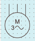
3.2.6.2 Induction Motor with Wound Rotor, three Phase
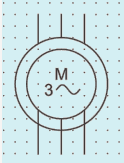
3.2.6.3 Induction Motor, Three-Phase, Star-Connected
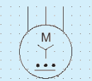
3.2.6.4 Linear Induction Motor, Three-Phase
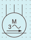
3.2.7 Transformers with two Separate Windings

3.2.8 Auto-Transformer

3.2.9 Three-Phase Transformer
3.2.9.1 Three-Phase Transformer, Connection Star-Delta/Form 1
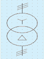
29
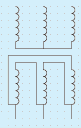
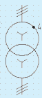
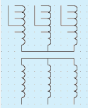
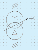
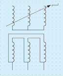
3.2.9.7 Three-Phase Transformer, Connection Star ‒ Zigzag with the Neutral brought out/Form 1
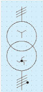
3.2.9.8 Three-Phase Transformer, Connection Star ‒ Zigzag with the Neutral brought out/Form 2
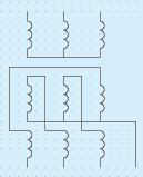
3.2.9.9 Three-Phase Transformer, Connection Star ‒ Star-Delta/Form 1
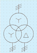
3.2.9.10 Three-Phase Transformer, Connection Star ‒ Star-Delta/Form 2
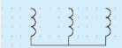

3.2.10 Starter

3.2.11 Direct-on-Line Starter for Reversing Motor

SP 30 : 2023
3.2.12 Star-delta Starter

3.2.13 Auto-transformer Starter

3.2.14 Rheostatic Starter

3.2.15 Switch

3.2.16 Contactor

3.2.17 Relay
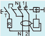
3.2.18 Circuit-breaker

3.2.19 Isolator

3.2.20 Residual Current Circuit Breaker

3.2.21 Overvoltage Protection Device

3.2.22 Fuse

3.2.23 Signal Lamp

3.2.24 Link

3.2.25 Distribution Board, Cubicle Box, Main Fuse Board with Switches

3.2.26 Socket Outlet, 6A

3.2.27 Socket Outlet, 16A

3.2.28 Plug

3.2.29 Voltmeter

3.2.30 Ammeter A
3.2.31 Wattmeter W
3.2.32 Varmeter lar
3.2.33 Power Factor Meter Cos φ
3.2.34 Ohmmeter Ω
3.2.35 Indicating Instrument (General Symbol)
3.2.36 Recording Instrument (General Symbol)
3.2.37 Integrating Meter

3.2.38 Watthour Meter Wh
3.2.39 Clock
3.2.40 Master Clock
3.2.41 Current Transformer

3.2.42 Voltage Transformer

3.2.43 Wiring on the Surface

3.2.44 Wiring in Conduit

3.2.45 Lamp

3.2.46 Lamp Mounted on a Ceiling

3.2.47 Emergency Lamp

3.2.48 Spot Light

3.2.49 Flood Light

3.2.50 Heater

3.2.51 Storage Type Water Heaters

3.2.52 Bell

SP 30 : 2023
3.2.53 Buzzer

3.2.55 Ceiling Fan

3.2.55 Exhaust Fan

3.2.56 Fan Regulator

3.2.57 Aerial

3.2.58 Radio Receiving Set

3.2.59 Television Receiving Set

3.2.60 Manually Operated Fire Alarm

3.2.61 Soft Starter

3.3 Solar PV and EV charging
3.3.1 Grid tie Inverter

3.3.2 Bidirectional Meter

3.3.3 Electric Charging Station
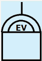
3.3.4 Electric Charging Point

3.2.5 Automatic Fire Detector Switch

4 LETTER, SYMBOLS AND SIGNS
NOTES
1 A location diagram need not necessarilym be to the scale.
2 Several types of diagrams may be combined into a single diagram, forming a mixed diagram. The same drawing may form both an explanatory and wiring diagram.
b) Architectural diagrams; and
c) Network diagrams.
NOTE — Several of these methods of representation may be used on the same diagram.
| Expression in Terms of SI Base Units |
|---|
| Selection of Multiples |
|---|
| (1) | (2) | (3) | (4) | (5) | (6) | (7) |
| i) | Electric current | ampere | A | - | - | kA, mA, µA, nA, pA |
| ii) | Power | watt | W | J/s | m<sup>2</sup>.kgs<sup>-3</sup> | GW, MW, kW, mW, µ W |
| iii) | Quantity of electricity, electric charge | coulomb | C | - | s.A | kC, µC, nC, pC |
| iv) | Electric potential, potential difference, electromotive force | volt | V | W/A | m<sup>2</sup>.kgs<sup>-3</sup>.A<sup>-1</sup> | MV, kV, mV, µ V |
| v) | Capacitance | farad | F | C/V | m<sup>2</sup>.kg.s<sup>-1</sup>.A<sup>-1</sup> | mF, µF, nF, pF |
| vi) | Electrical resistance | ohm | Ω | V/A | m<sup>2</sup>.kg.s<sup>-1</sup>.A<sup>-2</sup> | G Ω, M Ω. K Ω, m Ω,... µ Ω |
| vii) | Conductance | siemens | S | A/V | m<sup>-2</sup>.kg<sup>-1</sup>.s<sup>-1</sup> | kS, mS, µS |
| viii) | Magnetic flux | weber | Wb | V.s | m<sup>2</sup>.kg.s<sup>-2</sup>.A<sup>-1</sup> | mWb |
| ix) | magnetic flux density | tesla | T | Wb/m<sup>2</sup> | kg.s<sup>-1</sup>.A<sup>-1</sup> | mT, µT. nT |
| x) | Inductance | henry | H | Wb/A | m<sup>2</sup>.kg.s<sup>-2</sup>.A<sup>-2</sup> | mH, µH, nH, pH |
| xi) | Conductivity | siemens/metre | S/m | - | m<sup>1</sup>.kg<sup>-1</sup>.S<sup>1</sup>, A<sup>1</sup> | MS/m, kS/m |
| xii) | Electric field strength | volt/metre | V/m | - | m.kg.s<sup>-1</sup>.A<sup>-1</sup> | MV/m, kV/m or V/mm, V/m, mV/m, µV/m |
| xiii) | Permeability | henry/metre | H/m | - | m.kg.s<sup>-2</sup>.A<sup>-2</sup> | µH/m, nH/m |
| xiv) | Permittivity | farad per metre | F/m | - | m<sup>-1</sup>.kg<sup>-1</sup>.s<sup>4</sup>.A<sup>2</sup> | µF/m, nF/m, pF/m |
| xv) | Reluctance | 1 per henry | H<sup>-1</sup> | - | m<sup>-2</sup>.kg<sup>-1</sup>.s<sup>2</sup>.A<sup>2</sup> | - |
| xvi) | Resistivity | Ohm metre | Ω.m | - | m<sup>1</sup>.kg.s<sup>-1</sup>.A<sup>-2</sup> | G Ω m, M Ω m, k Ω m, Ωcm, m Ω m, v Ω m, n Ω m |
SP 30 : 2023
Locations of spaces/room shall be suitable to concerned building/utility service provider from the point of view of minimizing system losses, easy access and facility to repair and maintain.
Allocating space and providing civil work (for example, ducts, shafts, openings, space above false ceiling and below the beam soffit) along the routes of building/utility services shall also be considered at planning stage with required sizes.
Specific ventilation requirement of any particular equipment shall be taken care of (for example, battery rooms and equipment like transformers requiring adequate heat dissipation).
External influences (for example, climatic factors such as rains, sunlight, air quality like humidity, corrosive environments, dusty environment etc. affecting safety, service life, continuity and functionality of electrical installation shall also be considered to adopt required preventive measures.
This requirement shall be considered from the point of view of energy conservation such as solar panels of water heating system and PV systems require shadowless and are usually placed on terrace. NOTE — Use of renewable energy is counted under credit points while evaluating Green Building.
Building/utility service provider shall envisage future requirement and make the required provisions.
SP 30 : 2023
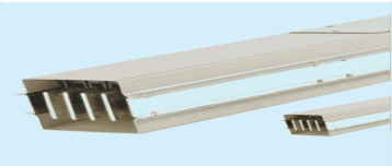
Fig. 2 Air-Insulated Bus-Bar Trunking
5.3.2.5 Sandwich bus is compact. It requires lesser space and there exist no risk of chimney effect.
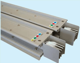
Fig. 3 Sandwich Bus Trunking
5.3.2.6 BTS of lower current range is also available for secondary distribution, for example, utility plug-in power outlets, lighting bus bar trunking etc. It may support dual circuits. Its applications is recommended in commercial establishments, shopping centers, IT parks, work benches in workshops/assembly lines in industries, hospitals, laboratories, warehouses/godowns etc. It enables easier maintenance. Lighting bus-bar trunking is convenient for high-bay illumination.
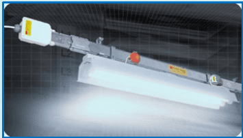
Fig. 4 Lighting Bus-Bar Trunking
| Table 3 (Concluded) | Table 3 (Concluded) | Table 3 (Concluded) |
| Table | Particulars | Use |
| B-3 | Current carrying capacities in amperes for XLPE/EPR insulation two loaded conductors at temperature 90°C in air and 20°C in ground | Provides current carrying capacities under methods of installation A1, A2, B1, B2, C, D1, D2 |
| B-4 | Current carrying capacities in amperes for PVC insulation three loaded conductors at temperature 70°C in air and 20°C in ground | Provides current carrying capacities under methods of installation A1, A2, B1, B2, C, D1, D2 |
| B-5 | Current carrying capacities in amperes for XLPE/EPR insulation three loaded conductors at temperature 90°C in air and 20°C in ground | Provides current carrying capacities under methods of installation A1, A2, B1, B2, C, D1, D2 |
| B-6 | Current carrying capacities in amperes for mineral insulation copper conductor and sheath/PVC covered or bare, two/ three loaded conductors at metallic sheath exposed to touch temperature 70°C with ambient temperature 30°C | Provides current carrying capacities for copper conductor (1.5 to 4 mm2 at 500 V and 1.5 to 240 mm2 at 750 V) under C methods of installation. |
| B-7 | Current carrying capacities in amperes at metallic sheath not exposed to touch at temperature 105°C with ambient temperature 30°C | Provides current carrying capacities for copper conductor (1.5 to 4 mm2 at 500 V and 1.5 to 240 mm2 at 750 V) under C methods of installation. |
| B-8 | Current carrying capacities in amperes at metallic sheath exposed to touch temperature 70°C with ambient temperature 30°C | Provides current carrying capacities for copper conductor (1.5 to 4 mm2 at 500 V and 1.5 to 240 mm2 at 750 V) under E, F and G methods of installation. |
| B-9 | Current carrying capacities in amperes at metallic sheath not exposed to touch at temperature 105°C with ambient temperature 30°C | Provides current carrying capacities for copper conductor (1.5 to 4 mm2 at 500 V and 1.5 to 240 mm2 at 750 V) under E, F and G methods of installation. |
| B-10 | Current carrying capacities in amperes for PVC insulated, single/multi core cables copper (1.5 to 630 mm2) conductor temperature 70°C with ambient temperature 30°C | Provides current carrying capacities under methods of installation E, F and G |
| B-11 | Current carrying capacities in amperes for aluminium (>16 to 630 mm2) conductor temperature 70°C with ambient temperature 30°C | Provides current carrying capacities under methods of installation E, F and G |
| B-12 | Current carrying capacities in amperes for XLPE/EPR insulation copper conductor (1.5 to 630 mm2), temperature 90°C at reference ambient temperature of 30°C | Provides current carrying capacities under methods of installation E, F and G |
| B-13 | Current carrying capacities in amperes for aluminium conductor at reference ambient temperature of 30°C | Provides current carrying capacities under methods of installation E, F and G |
| B-14 | Correction factor for ambient air temperature other than 30°C | Values given in Table B-2 to Table B-13 shall be used after applying correction factor in respect with the air ambient temperature |
| B-15 | Correction factor for ambient ground temperature other than 200°C | Values given in Tables B-2 to Table B-5 shall be used after applying correction factor in respect with the ground ambient temperature |
| B-16 | Correction factors for cables buried directly in ground/ducts for soil thermal resistivity other than 2.5 K-m/W | Values given in Table B-2 to Table B-5 for reference method D shall be used after applying correction factor |
| B-17 | Reduction factor for one circuit/more than one circuit or one multi-core cable/more than one multi-core cable other than underground | Values mentioned in Tables B-2 to Table B-13 shall be used after applying the reduction factor |
| B-18 | Reduction factor for one circuit/more than one circuit or one multi-core cable/more than one multi-core cable laid directly underground | Values mentioned in Table B-2 to Table B-5 shall be used after applying the reduction factor, for installation method D2 |
| B-19 | Reduction factor for one circuit/more than one circuit or one multi-core cable/more than one multi-core cable laid in duct in ground | Values mentioned in Table B-2 to Table B-5 shall be used after applying the reduction factor, for installation method D1 |
| B-20 | Reduction factor for group of more than one multi-core cable to be applied to reference current carrying capacities for multi-core cable in free air | Values given in Table B-8 to Table B-13 for reference method E shall be used after applying correction factor |
| B-21 | Reduction factor for group of more than one circuit of single-core cables to be applied to reference current carrying capacities for one circuit of single-core cable in free air | Values given in Table B-8 to Table B-13 for reference method F shall be used after applying reduction factor |
NOTE — Refer Tables B -1 to Table B-21 of Annex B
For this load a 10 mm2 cable is suitable.
Example 3 If 50 percent third harmonic is present; the cable size is again selected on the basis of neutral current which is:
3 9 * 0. 5 * 3 = 5 8. 5 A
In this case, the reduction factor is 1 and hence, 16 mm2 cable is required.
NOTES
1 All the above cable selections are based on the current-carrying capacity of the cable, voltage-drop and other aspects of design have not been considered.
2 Also see 5.8.4.1 and 5.8.4.2.
NOTE — Conduits shall be comply with the requirements mentioned with IS 9537 (Part 3).
Size of conduit shall be decided on the basis of number of cables which can be easily and safely drawn within, without exceeding the limit of temperature rise (see Table 2) at full load under normal conditions and under that respective situation. For deciding the size of conduit, inside cross-sectional area of conduit, cross-sectional area of cable/s (calculated from the maximum overall diameter) and number of cables form basis of area to be occupied/ filled by cables. Fill factor shall not exceed values as given below:
a) One cable 53 percent
b) Two cables 31 percent
c) Three or more cables 40 percent
References may be taken from Table D-2 [Refer 7.1 of IS 9537 (Part 2)], Table D-3 [see 7.1 of IS 9537(Part 3)] and Table D-4 (see 16.1.2 and 16.1.3 of IS 694) given under Annex D.
NOTE — Between pull boxes, for every two deviations in direction of up to 900, area of conduit shall be considered less by 15 percent. There shall be no further deviation.
Fig. 7 Bends in Conduits
Upper part of figure shows 90° bend and lower part of figure shows four bends each of 45° aggregating to 180°.
To find suitable Heavy PVC conduit for: Number of cables (stranded): 2*1.5 mm2 (1 run) 2* 4.0 mm2 (1 run) 1* 1.5 mm2 (1 run)
Number of bends 2 Nos. of 90° To find Size of conduit: Cross sectional area of cables from Table D-4 of Annex D Class 2 - 1.5 mm2 - 8.55 mm2 Class 2 - 4.0 mm2 - 16.62 mm2 Fill area = (5*8.55) + (2*16.62) = 75.99 mm2 Since number of cables are 7, Fill factor – 40 percent 75.99/0.4 = 189.98 ≈ 190
Nearest and next cross sectional. area of conduit from Table D-3 of Annex D and since there are 2 bends of 90° area to be reduced by 15 percent
196 mm2 20 mm conduit
333 mm2 25 mm conduit
Less 15
196*.85 = 166.6 mm2 - It is less than 190 mm2
Next size
333*.85 = 283.5 mm2 - It is more than 190 mm2.
NATIONAL ELECTRICAL CODE OF INDIA
So suitable conduit size is 25 mm
Conduit fittings shall comply with requirements of IS 3419. Provision of suitable fittings, junction and/or draw-in boxes shall be checked by inspection.
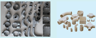
Fig. 9 Conduit Fittings
81
Elbows/tees (for use in surface wiring) shall be made at the locations where there are sharp changes in direction, to facilitate drawing of wires. Provision shall be made after every 3 m.
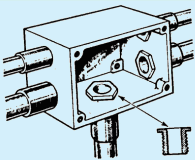
Fig. 10 Draw in Box in Metal Conduit System
a) Within conduit system, there shall be no sharp edges, burrs or surface projections which may damage insulated conductor/cable or inflict injury to the installer or user.
NOTE — Often burr forms while cutting and threading the conduit and is more significant in case of metal conduits. It shall be carefully removed, and rubber bushes may be used at open ends of the conduits, before drawing of cables so that the insulation is not damaged.
At expansion joints of buildings, necessary care shall be taken to use suitable flexible conduit/necessary fittings to sustain anticipated movement to not cause damage to the electrical equipment.
All penetrations/entries through civil work like walls, slabs, floor, roofs etc. shall be sealed such that the planned fire resistance of all elements are not compromised.
To ensure safety in electrical installations, use of metal conduits as earth continuity conductor shall not be permitted in general.
NOTE — If circumstances require conduit system to be used as protective conductor, the system shall be tested after final installation and also, shall be periodically checked to confirm its suitability for purpose.
All joints of conduits with fittings and accessories shall be made rigid with the resin/PVC solvent cement as recommended by the manufacturer. Such solvent shall be applied on the portions of conduit/fittings to be joined. Then, such portions shall be pushed in and held for 30 - 60 s as instructed by manufacturer. This part of installation procedure is important from the point of view of required degree of ingress protection (IP).
To make metal conduit system rigid, fittings with draw-in/inspection boxes shall be secured with checknuts (see Fig. 10). Exposed portion of threading shall be coated with anti-corrosive paint. Sealants shall be applied at all joints as per desired Ingress Protection (IP).
Bending of metal conduits shall be done with proper pipe benders, a tool which allows bending of pipe at right angle/off-set at any required angle (see Fig. 11). Pipe bending of PVC conduits shall be done with spring as specified by the manufacturer. A person shall be acquainted with the technique to calculate required lengths of conduits considering expansions/shrinks occurring in conduits due to bending. Typical manual pipe benders for metal conduit and spring for PVC conduit is shown in Fig. 11.
Fig. 11 Metal Pipe Bender
Fig. 12 PVC Conduit Bending Springs
Bending of conduits requires skill and shall be performed by competent person.
h) Concealed conduit system in RCC work of slab or other - Conduits
The conduits shall be fixed to steel with binding wire, especially, at the points of joints. Multiple crossings shall be avoided in the slabs to allow proper concreting thickness.
j) Concealed conduit system in RCC work of slab or other - Deep junction/draw-in boxes
Deep junction/draw-in boxes of 65mm depth or as required shall be used, depending on thickness of concreting. They shall be filled with dry sand or stuffed with suitable material and fixed with removable cover, so that the slurry does not enter and block/choke the routes of cabling and stuffed material may later be removed easily.
Care shall be taken while installing concrete covers so that erected conduit system is not disturbed/ shifted, especially, at joints. Also, while pouring concrete in beams/columns, disturbance may be caused to installed conduit system due to use of vibrators. Hence, supervision and vigil while carrying out the task shall be ensured.
Proper care shall be taken while making chases so as to avoid weakening of walls. Conduits shall be fixed with clamps/U nails or by some other means if necessary. Care shall be taken for installation in internal walls to avoid back to back fixing of boxes and conduits, particularly, in 4 inches walls.
| Sl No. | Type | Current ( In ) | Time (t) | Result |
| (1) | (2) | (3) | (4) | (5) |
| i) | B, C, D | 1.13 In | t < 1h (In < 63A) t < 2h (In > 63A) | No trip when colda) |
| ii) | B, C, D | 1.45 In | t < 1h (In < 63A) t < 2h (In < 63A) | Trip when not cold |
| iii) | B, C, D | 2.55 In | 1 s < t < 60 s (In < 32A) 1 s < t < 120 s (In > 32A) | Trip when cold |
| iv) | B | 3 In | No trip when cold | |
| C | 5 In | t < 0.1 s | ||
| D | 10 In | |||
| v) | B | 5 In | Trip when cold | |
| C | 10 In | t > 0.1 s | ||
| D | 20 In | |||
| a) The term cold means without previous loading | ||||
NOTE — Conventional non-tripping current of circuit breaker is 1.13 I n and conventional tripping current is 1.45 I n ∗ Precise selection shall be done considering these points, overloading and in-surge of current.
MCBs are generally available at 3kA, 6kA and 10kA short-circuit current rating. If details are available to calculate fault current rating, suitable MCB shall be selected. However, when the details of suppliers’ distribution network are not available, it is recommended that MCB of 10kA short-circuit current rating shall be selected.
NOTE — Electrical installation which is next to/very near to the distribution transformer of higher capacity may have higher fault level. Under such cases, it may be necessary to increase size of cable. For such cases, MCB of rated current capacity may not match requirement of fault level/terminal size. Under these circumstances, in place of MCB, use of MCCB is recommended.
NOTE — Individual phase Isolation type DBs shall be of help which will trip the supply of particular phase only.
RCDs having 300mA sensitivity, intended for fire protection may be placed at main switchboards/incoming source of supply or at such a location to address fire prevention and spread of fire.
For electrical loads exceeding 125 A, sectionalizing shall be done considering maximum current rating of 125 A.
Proper sectionalizing is necessary to avoid false tripping. Where RCCBs are installed in series, discrimination shall be such that nearest RCCs shall trip first. To achieve such condition, S type RCCBs with time delay setting may be used. Increasing sensitivity level shall not be permitted.
NOTE — Accumulated currents in protective conductor may cause RCD to operate under non fault condition (for example, current developed by SMPS of multiple computers, when too many computers are connected on a circuit etc.). To avoid such circumstances, proper sectionalizing is necessary.
ACBs can be fixed or draw-out type. The racking-out can be mechanical or electrical.
Service life of ACBs is higher compared to MCCBs but ACBs need regular maintenance and is expensive.
105
This device is intended to mitigate effect of arcing faults by disconnecting the circuit when the arc fault is detected. It shall be noted that RCDs are recognised as efficient to reduce the risk of fire by detection of leakage current and arcing to ground. But they cannot reduce risk of electrical fire due to series or parallel arcing between live conductors. In series fault, impedance of series fault reduces current which may be below the threshold of circuit breaker tripping. Another point of consideration is frequency under arcing fault may be higher than 50 Hz. Hence, AFDD is effective to mitigate risk of fire ignition when arcing persists and also, protects against fire ignition due to over-voltages caused by broken neutral in three phase installation. It shall be used in single phase and three phase installation up to 440 V a.c. with rated current not exceeding 63 A.
Selection of breaker shall consider the features in above mentioned clauses. Rating shall suit the ambient temperature and maximum current carrying capacity of cable. Variable setting is preferable to suit varying load pattern. Other auxiliary protections shall be provided as per requirement of system and equipments to be connected.
Installation of switches shall always be on phase/line conductor. Switch shall not disconnect neutral wire unless it is a two-pole switch where neutral disconnects simultaneously with phase conductor of the same circuit provided the neutral is not looped further to any other circuit/point.
Depending on type of switch, its mounting on plate/board may be press fit type or may be through screws and nuts. After the switches are mounted and wired, no live parts shall remain open and accessible to the user.
Points requiring control from two locations, where two-way switches are used, it shall be ensured that neutral wire is not fed from either side and the phase wire used from both ends is of the same circuit.
For power points 16 A and above, indicating switches are recommended so that ON/OFF supply is noticeable an alert signal.
Switches with marking help in distinction of switches for light, fan or bell etc. especially where there are a number of switches.
Supply to plug socket shall be given through a switch of current rating not less than that of socket be placed at adjacent position in the switch board. Plug socket provided on lighting circuit switch board shall not be more than 6A. For power circuits, 16A or combined 6/16A sockets shall be used.
Where multiple 6A sockets are to be controlled with a single switch, they shall be located on a single board and a permanent marking shall be done on such sockets to identify such situations. Considering the total possible load, rating of switch shall be selected. Circuit to each such switch board shall be independent and shall not be looped from any other lighting switch board.
NOTE — As far as possible such situation shall be avoided, but in case of requirement for number of equipment forming a part of a single system and requiring simultaneous operation and equipment connected having an individual built in switch, such method of may be adopted (for example, CPU, monitor, add-on speakers, printer of CPU etc.).


Fig. 31 Fan Hook Box Concealed Type And Bar To Be Fastened/Entangled With Steel in RCC
Fig. 32 Type Of Hooks To Be Grouted With Anchor Bolts in RCC Slab
Fig. 33 Shackle And Bolt Type Arrangement for Fan Suspension, Fan Clamp
Rod shall be of 10mm diameter and M.S. flat of clamp shall not be less than 30 mm × 5 mm.
It shall be noted that electrical continuity is disrupted with use of rubber shackle from fan to the metallic part of ceiling. Rubber shackle also helps to dampen torsion forces.
b) Down Rod — Down rod or suspension rod of ceiling fan are of standard length, usually of 225 mm, and with necessary holes for nut and bolts, wire to pass through and cut for clamping fan shaft with proper grip (see Fig. 34). In case of ceiling height more than 3 m, extra long down rod may be required. Under such circumstances check, manufacturer’s specifications shall be checked for recommended maximum height of blades from floor level for optimum output/useful air delivery.
Down rods with extra lengths shall be continuous without joint and shall carry same mechanical properties.
NOTE — If joints in down rod are unavoidable, then, such joints shall be screwed to special couplers of minimum length of 50 mm and both ends of the rod shall be secured by means of split pins or may be by welding.
Fig. 34 Down Rod with Arrangement for Wires and Suspension
Alternatively, screwed type suspension may be allowed subject to condition that the threads tightens when the fan is in motion.
Clearances — Recommended clearances of fan blades from finished level of flooring and ceiling shall not be less than 2400 mm and 300 mm respectively.
Connections — Connection shall be made with twin core copper wire of size not less than 1.5 mm2 qualifying under class II appliances or three core 1.5 mm2 qualifying under class I appliances. Earth wire of three core cord shall be terminated on the earth terminal of fan provided by the manufacturer.
Wiring connections on switch board shall be from switch through fan speed regulator.
Where air changes are required to maintain fresh air flow to maintain air quality, provision of exhaust Fans shall be made. Exhaust fans shall conform to IS 2312. Exhaust fan are also available with reversible flow (fresh air intake) facility which can be availed through toggle switch.
Selection of exhaust fans can be done on the basis of:
a) blade sweep size in mm;
b) air changes, in CFM or m3/min;
c) service value, m3/min/W;
d) voltage level 240 V/415 V; and
e) power input W.
Recommended values of air changes depending on application are given under 5.2.2.1 of Volume 2/Part 8 of NBC 2016. Some of the common applications are as in the Table 17.
Table 17 Recommended Air-Changes
(Clause 9.2.2.1)
| Sl No. | Application | Air Changes/Hour* |
|---|---|---|
| (1) | (2) | (3) |
| i) | Bathrooms | 6-10 |
| ii) | Bed rooms | 2-4 |
| (iii) | Canteens | 8-12 |
| iv) | Garages | 6-8 |
| v) | Lavatories | 6-15 |
SP 30 : 2023
| Sl No. | Application | Air Changes/Hour* |
| (1) | (2) | (3) |
| vi) | Offices | 6-10 |
| vii) | Restaurants | 8-12 |
| viii) | Shower baths | 15-20 |
| ix) | Stores and warehouses | 3-6 |
| x) | Toilets | 6-10 |
| * Volume of air to be replaced contained in a room/envelope in an hour | ||
To find required CFM (cubic feet per minute – imperial measure) or m3/min (System of International units, SI) for a bathroom:
Bath room size > 4 in × 7 in × 10 in or 1.2 m × 2.1 m × 3 m
Volume = 280 cu. ft or 7.56 m3
Number of air changes considered = 8
Volume of air is to be replaced in an hour
= 2 8 0 × 8 or 7. 5 6 × 8
= 2 4 4 0 cu.ftor 6 0. 4 8 m ³
Required cfm or m3/min capacity of fan
= 2 4 4 0 / 6 0 or 6 0. 4 8 / 6 0
Accordingly, size of fan having capacity not less than calculated above shall be selected. Details with respect to cfm if not available on name plate may be sought from the manufacturer.
Installation of exhaust fan needs coordination with civil work agencies. A recess/opening suiting the required size of exhaust fan with mounting arrangement is necessary. The opening may be on wall/ window frame. There shall be protection from ingress of water. There shall be arrangement for entry of fresh air so that negative pressure does not develop within the area (see 4.4.10).
Mounting shall be done with suitable measures to reduce vibrations. Suitably designed guard shall be fixed to prevent entry of flora/fauna.
Connections from ceiling rose shall be made with twin core copper wire of size not less than 1.5 mm2 for fan qualifying under class II appliances or three core 1.5 mm2 qualifying under class I appliances. Earth wire of three core cord shall be terminated on the earth terminal of fan provided by the manufacturer.
| + Follow manufacturer's instructions. |
| NOTE — The numeral in table refers to S. No. of method of installation in Table A-3. |
| 321 |
| 291 |
| 400 |
| 344 |
| 461 |
| 336 |
| 382 |
| 300 | 367 | 334 | 458 | 394 | 530 | 379 | 427 |
| Aluminium |
| 2.5 | 15 | 14.5 | 18.5 | 17.5 | 21 | 22 |
| 4 | 20 | 19.5 | 25 | 24 | 28 | 29 |
| 6 | 26 | 25 | 32 | 30 | 36 | 36 |
| 10 | 36 | 33 | 44 | 41 | 49 | 47 |
| 16 | 48 | 44 | 60 | 54 | 66 | 61 | 63 |
| 25 | 63 | 58 | 79 | 71 | 83 | 77 | 82 |
| 35 | 77 | 71 | 97 | 86 | 103 | 93 | 98 |
| 50 | 93 | 86 | 118 | 104 | 125 | 109 | 117 |
| 70 | 118 | 108 | 150 | 131 | 160 | 135 | 145 |
| 95 | 142 | 130 | 181 | 157 | 195 | 159 | 173 |
| 120 | 164 | 150 | 210 | 181 | 226 | 180 | 200 |
| 150 | 189 | 172 | 234 | 201 | 261 | 204 | 224 |
| 185 | 215 | 195 | 266 | 230 | 298 | 228 | 255 |
| 240 | 252 | 229 | 312 | 269 | 352 | 262 | 298 |
| 300 | 289 | 263 | 358 | 308 | 406 | 296 | 336 |
| NOTE — In Col (3), (5), (6), (7) and (8), circular conductors are assumed for sizes up to and including 16 mm² . Values for larger sizes relate to shaped conductors and may safely be applied to circular conductors. |
| 424 |
| 386 |
| 528 |
| 459 |
| 599 |
| 395 |
| 448 |
| 300 | 486 | 442 | 603 | 532 | 693 | 446 | 502 |
| Aluminium |
| 2.5 | 20 | 19.5 | 25 | 23 | 26 | 26 |
| 4 | 27 | 26 | 33 | 31 | 35 | 33 |
| 6 | 35 | 33 | 43 | 40 | 45 | 42 |
| .10 | 48 | 45 | 59 | 54 | 62 | 55 |
| 16 | 64 | 60 | 79 | 72 | 84 | 71 | 76 |
| 25 | 84 | 78 | 105 | 94 | 101 | 90 | 98 |
| 35 | 103 | 96 | 130 | 115 | 126 | 108 | 117 |
| 50 | 125 | 115 | 157 | 138 | 154 | 128 | 139 |
| 70 | 158 | 145 | 200 | 175 | 198 | 158 | 170 |
| 95 | 191 | 175 | 242 | 210 | 241 | 186 | 204 |
| 120 | 220 | 201 | 281 | 242 | 280 | 211 | 233 |
| 150 | 253 | 230 | 307 | 261 | 324 | 238 | 261 |
| 185 | 288 | 262 | 351 | 300 | 371 | 267 | 296 |
| 240 | 338 | 307 | 412 | 358 | 439 | 307 | 343 |
| 300 | 387 | 352 | 471 | 415 | 508 | 346 | 386 |
| NOTE — In Col (3), (5), (6), (7) and (8), circular conductors are assumed for sizes up to and including 16 mm² . Values for larger sizes relate to shaped conductors and may safely be applied to circular conductors. |
| 278 |
| 240 | 286 | 261 | 346 | 297 | 403 | 280 | 320 |
| 300 | 328 | 298 | 394 | 339 | 464 | 316 | 359 |
| Aluminium |
| 2.5 | 14 | 13.5 | 16.5 | 15.5 | 18.5 | 18.5 |
| 4 | 18.5 | 17.5 | 22 | 21 | 25 | 24 |
| 6 | 24 | 23 | 28 | 27 | 32 | 30 |
| 10 | 32 | 31 | 39 | 36 | 44 | 39 |
| 16 | 43 | 41 | 53 | 48 | 59 | 50 | 53 |
| 25 | 57 | 53 | 70 | 62 | 73 | 64 | 69 |
| 35 | 70 | 65 | 86 | 77 | 90 | 77 | 83 |
| 50 | 84 | 78 | 104 | 92 | 110 | 91 | 99 |
| 70 | 107 | 98 | 133 | 116 | 140 | 112 | 122 |
| 95 | 129 | 118 | 161 | 139 | 170 | 132 | 148 |
| 120 | 149 | 135 | 186 | 160 | 197 | 150 | 169 |
| 150 | 170 | 155 | 204 | 176 | 227 | 169 | 189 |
| 185 | 194 | 176 | 230 | 199 | 259 | 190 | 214 |
| 240 | 227 | 207 | 269 | 232 | 305 | 218 | 250 |
| 300 | 261 | 237 | 306 | 265 | 351 | 247 | 282 |
| NOTE — In Col (3), (5), (6), (7) and (8), circular conductors are assumed for sizes up to and including 16 mm² . Values for larger sizes relate to shaped conductors and may safely be applied to circular conductors. |
| 324 |
| 240 | 380 | 346 | 450 | 398 | 500 | 324 | 375 |
| 300 | 435 | 396 | 514 | 455 | 576 | 365 | 419 |
| Aluminium |
| 2.5 | 19 | 18 | 22 | 21 | 24 | 22 |
| 4 | 25 | 24 | 29 | 28 | 32 | 28 |
| 6 | 32 | 31 | 38 | 35 | 41 | 35 |
| 10 | 44 | 41 | 52 | 48 | 57 | 46 |
| 16 | 58 | 55 | 71 | 64 | 76 | 59 | 64 |
| 25 | 76 | 71 | 93 | 84 | 90 | 75 | 82 |
| 35 | 94 | 87 | 116 | 103 | 112 | 90 | 98 |
| 50 | 113 | 104 | 140 | 124 | 136 | 106 | 117 |
| 70 | 142 | 131 | 179 | 156 | 174 | 130 | 144 |
| 95 | 171 | 157 | 217 | 188 | 211 | 154 | 172 |
| 120 | 197 | 180 | 251 | 216 | 245 | 174 | 197 |
| 150 | 226 | 206 | 267 | 240 | 283 | 197 | 220 |
| 185 | 256 | 233 | 300 | 272 | 323 | 220 | 250 |
| 240 | 300 | 273 | 351 | 318 | 382 | 253 | 290 |
| 300 | 344 | 313 | 402 | 364 | 440 | 286 | 326 |
| NOTE — In Col (3), (5), (6), (7) and (8), circular conductors are assumed for sizes up to and including 16 mm² . Values for larger sizes relate to shaped conductors and may safely be applied to circular conductors. |
| 4 500 V and 750 V are rated voltages of the cable. |
| 400 |
| 454 |
| 185 | 472 | 399 | 426 | 446 | 507 |
| 240 | 552 | 466 | 496 | 497 | 565 |
| NOTES |
| 1 For single-core cables, sheaths of cables of the circuit are connected together at both ends. |
| 2 For bare cables exposed to touch, values should be multiplied by 0.9. |
| 3 De is the external diameter of the cable. |
| 4 500 V and 750 V are the rated voltages of the cable. |
| 565 |
| 185 | 596 | 500 | 530 | 557 | 629 |
| 240 | 697 | 584 | 617 | 624 | 704 |
| NOTES |
| 1 For single-core cables, sheaths of cables of the circuit are connected together at both ends. |
| 2 For bare cables exposed to touch, values should be multiplied by 0.9. |
| 3 De is the external diameter of the cable. |
| 4 500 V and 750 V are the rated voltages of the cable. |
| 406 |
| 356 |
| 372 |
| 456 |
| 419 |
| 185 | 434 | 364 | 463 | 409 | 427 | 521 | 480 |
| 240 | 514 | 430 | 546 | 485 | 507 | 615 | 569 |
| 300 | 593 | 497 | 629 | 561 | 587 | 709 | 659 |
| 400 | - | - | 754 | 656 | 689 | 852 | 795 |
| 500 | - | - | 868 | 749 | 789 | 982 | 920 |
| 630 | - | - | 1 005 | 855 | 905 | 1 138 | 1 070 |
| NOTES |
| 1 Circular conductors are assumed for sizes up to and including 16 mm² . Values for larger sizes relate to shaped conductors and may safely be applied to circular conductors. |
| 2 De is the external diameter of the cable. |
| 316 |
| 274 |
| 287 |
| 356 |
| 327 |
| 185 | 322 | 280 | 363 | 315 | 330 | 407 | 376 |
| 240 | 380 | 330 | 430 | 375 | 392 | 482 | 447 |
| 300 | 439 | 381 | 497 | 434 | 455 | 557 | 519 |
| 400 | - | - | 600 | 526 | 552 | 671 | 629 |
| 500 | - | - | 694 | 610 | 640 | 775 | 730 |
| 630 | - | - | 808 | 711 | 746 | 900 | 852 |
| NOTES |
| 1 Circular conductors are assumed for sizes up to and including 16 mm² . Values for larger sizes relate to shaped conductors and may safely be applied to circular conductors. |
| 2 De is the external diameter of the cable. |
| 437 |
| 383 |
| 400 |
| 500 |
| 454 |
| 150 | 473 | 399 | 504 | 444 | 464 | 577 | 527 |
| 185 | 542 | 456 | 575 | 510 | 533 | 661 | 605 |
| 240 | 641 | 538 | 679 | 607 | 634 | 781 | 719 |
| 300 | 741 | 621 | 783 | 703 | 736 | 902 | 833 |
| 400 | - | - | 940 | 823 | 868 | 1085 | 1008 |
| 500 | - | - | 1083 | 946 | 998 | 1253 | 1169 |
| 630 | - | - | 1 254 | 1 088 | 1 151 | 1 454 | 1 362 |
| NOTES |
| 1 Circular conductors are assumed for sizes up to and including 16 mm² . Values for larger sizes relate to shaped conductors and may safely be applied to circular conductors. |
| 2 De is the external diameter of the cable. |
| 347 |
| 447 |
| 395 |
| 413 |
| 515 |
| 470 |
| 240 | 470 | 409 | 530 | 471 | 492 | 611 | 561 |
| 300 | 543 | 471 | 613 | 547 | 571 | 708 | 652 |
| 400 | - | - | 740 | 663 | 694 | 856 | 792 |
| 500 | - | - | 856 | 770 | 806 | 991 | 921 |
| 630 | - | - | 996 | 899 | 942 | 1 154 | 1 077 |
| NOTES1 Circular conductors are assumed for sizes up to and including 16 mm² . Values for larger sizes relate to shaped conductors and may safely be applied to circular conductors.2 De is the external diameter of the cable. |
| 7 | 0.53 | 0.66 | 0.76 | 0.87 |
| 8 | 0.50 | 0.63 | 0.74 | 0.87 |
| 9 | 0.47 | 0.61 | 0.73 | 0.86 |
| 10 | 0.45 | 0.59 | 0.72 | 0.85 |
| 11 | 0.43 | 0.57 | 0.70 | 0.85 |
| 12 | 0.41 | 0.56 | 0.69 | 0.84 |
| 13 | 0.39 | 0.54 | 0.68 | 0.84 |
| 0.66 |
| 0.61 |
| 6 | 0.97 | 0.81 | 0.73 | 0.69 | 0.63 | 0.58 |
| Cable ladder systems, cleats, etc.(see Note 3) | 32 | Touching | 1 | 1.00 | 0.87 | 0.82 | 0.80 | 0.79 | 0.78 |
| 33 | 2 | 1.00 | 0.86 | 0.80 | 0.78 | 0.76 | 0.73 |
| 34 | 3 | 1.00 | 0.85 | 0.79 | 0.76 | 0.73 | 0.70 |
| 6 | 1.00 | 0.84 | 0.77 | 0.73 | 0.68 | 0.64 |
| vii) | Floor warming installations | No diversity allowable 2) | — | — |
| viii) | Water heaters thermal storage space heating installations | No diversity allowable 2) | — | — |
| ix) | Standard arrangements of final circuits n accordance with IS 732 | 100 Percent of current demand of largest circuit+40 Percent of current demand of every other circuit | 100 Percent of current demand of largest circuit+50 Percent of current demand of every other circuit | — |
| x) | Socket outlets other than those included in Sl. No. (ix) above and stationary equipment other than those listed above | 100 Percent of current demand of largest point40 Percent of current demand of every other point | 100 Percent of current demand of largest point75 Percent of current demand of every other point | 100 Percent of current demand of largest point75 Percent of current demand of every point in main rooms (dining rooms, etc.)40 Percent of current demand of every other point |
a) Basic protection (protection against direct contact);
b) Fault protection (protection against indirect contact); and
c) Additional protection.
Requirements for electrical separation for the supply of one item of current-using equipment shall be in accordance with 4.2.13 of IS 732.
c) Extra-low-voltage (SELV and PELV)
Requirements for extra-low-voltage (SELV and PELV) shall be in accordance with 4.2.14 of IS 732.
SP 30 : 2023
SP 30 : 2023
Where,
I B = design current for that circuit; (the line or neutral current in case of harmonic after applying correction factors);
I z = continuous current-carrying capacity of the cable;
I n = is the rated current or current setting selected of the protective device; and
I 2 = is the current ensuring effective operation in the conventional time of the protective device.
A cable with larger cross-sectional area shall be used where sustained overcurrent ≤ I 2 occurs.
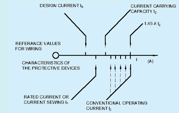
Fig. 1 Illustration of Condition 1 and 2
Where,
t = is the duration, in s;
S = is the cross-sectional area, in mm2;
I = is the effective short-circuit current, in A, expressed as an rms value; and
k = is a factor taking account of the resistivity, temperature coefficient and heat capacity of the conductor material, and the appropriate initial and final temperatures.
3.2 Risk Assessment Method — Calculated risk level (CRL) is used to determine if protection against transient overvoltages of atmospheric origin is required.
NOTE — For protection of a structure and its electrical systems against lightning and surges of atmospheric origin, IS/IEC 62305 applies.
The CRL is found by the following formula:
CRL = f env / (L p × N g)
where
a) f e n v is an environmental factor and the value of f e n v shall be calculated according to Table 1.
Table 1 Calculation of f e n v
(Clause 3.2)
| Sl No. | Environment | f<sub>env</sub> |
|---|---|---|
| (1) | (2) | (3) |
| i) | Rural and suburban environment | 85 × F |
| ii) | Urban environment | 850 × F |
The value of coefficient F shall be taken equal to 1 for all installations. However, National Committees may adjust the value of coefficient F from 1 to 3 for dwellings.
b) Ng is the lightning ground flash density (flash per km2 per year) relevant to the location of the power line and connected structure;
NOTE — According to A-1 of IS/IEC 62305-2, 25 thunderstorm days per year are equivalent to a value of 2.5 flashes per km2 per year. This is derived from the formula Ng = 0.1 × Td where T d is the number of thunderstorm days per year (keraunic level).
c) the risk assessment length, L p is calculated as below:
L p = 2 L PAL + L PCL + 0. 4 L PAH + 0. 2 L PCH
Where,
L P A L = the length (km) of low-voltage overhead line;
L P C L = the length (km) of low-voltage underground cable;
L P A H = the length (km) of high-voltage overhead line; and
L P C H = the length (km) of high-voltage underground cable.
The total length ( LPAL + LPCL + LPAH + LPCH ) is limited to 1 km or by the distance from the first overvoltage protective device installed in the power network to the entrance of the installation, whichever is the smaller.
If the distribution networks lengths are totally or partially unknown then L P A L shall be taken equal to the remaining distance to reach a total length of 1 km.
For example, if only the distance of underground cable is known (for example, 100 m), then the L p A L shall be taken equal to 90 m. An illustration of an installation showing the lengths to consider is given in Fig. 1.
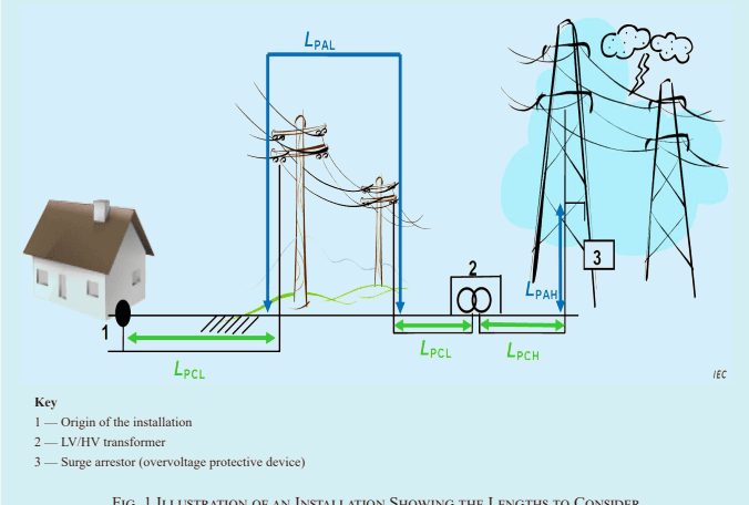
Fig. 1 Illustration of an Installation Showing the Lengths to Consider
If CRL ≥ 1 000, no protection against transient overvoltages of atmospheric origin is needed.
If CRL < 1 000, protection against transient overvoltages of atmospheric origin is required.
NOTE — Examples of calculations of CRL are given in Annex B.
c) Zero-sequence current I ( 0 ) ·
Taking the line L1 as reference the currents I L 1 , I L 2 and I L 3 are given by:
Where, a = - (1)/(2) + j(1)/(2)√(3); a² = - (1)/(2) - j(1)/(2)√(3).
Each of the three symmetrical component systems has its own impedance.
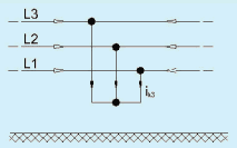
FIG4a- THREE PHASE SHORT CIRCUIT
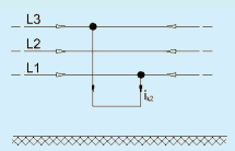
FIG4a- LINE TO LINE SHORT CIRCUIT
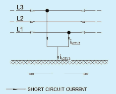
FIG4c- LINE TO LINE SHORT CIRCUIT WITH EARTH CONNECTION
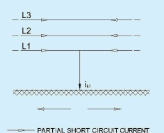
FIG4d- LINE TO EARTH SHORT CIRCUIT
Fig. 4 Characterization of Short Circuits and Their Current
The method of the symmetrical components postulates that the system impedances are balanced (for example, in the case of transposed lines). The results of the short-circuit calculation have an acceptable accuracy in the case of un-transposed lines.
When calculating maximum and minimum short circuit currents voltage factor C m a x o r C m i n from Table 1 shall be applied to compute maximum or minimum short circuit currents respectively.
| Table 1 Voltage Factor c(Clause 4.1.2.1.4) | |||
| Sl No. | Nominal Voltage Un | Voltage Factor c for the Calculation of | |
| Maximum Short-circuit Currents Cmax¹⁾ | Minimum Short-circuit Currents Cmin | ||
| (1) | (2) | (3) | (4) |
| i) | Low voltage | ||
| 100 V to 1 000 V(IEC 60038, table I) | 1.05³⁾ 1.10⁴⁾ | 0.95 | |
| ii) | Medium Voltage | ||
| >1 kV to 35 kV(IEC 60038, table III) | 1.10 | 1.00 | |
| iii) | High voltage²⁾ >35 kV(IEC 60038, table IV) | ||
| NOTES | |||
| 1 Cmax Un should not exceed the highest voltage Um for equipment of power systems.2 If no nominal voltage is defined Cmax Un = Um or Cmin Un = 0.90 × Um should be applied.3 For low-voltage systems with a tolerance of ±6 percent, for example systems renamed from 380 to 400 V.4 For low-voltage systems with a tolerance of +10 percent. | |||
For a far-from-generator short circuit fed from a single source (see Fig.1), the short-circuit current is calculated using equation (3).
where,
R k and X k are the sum of the series-connected resistances and reactance of the positive-sequence system respectively, in accordance with Fig. 5. R L is the line resistance for a conductor temperature of 2 0 ° C i when calculating the maximum short-circuit currents. Subscript Q and T refer feeder connecting point and transformer respectively.
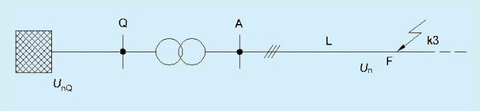
Fig. 5 Short Circuit FED from a Network Feeder VIA a Transformer
When there is more than one source contributing to the short-circuit current, and the sources are unmeshed, as shown for instance in Fig. 6, the initial symmetrical short-circuit current I k '' at the short-circuit location F is the sum of the individual branch short-circuit currents.
Each branch short-circuit current can be calculated as an independent single-source three-phase short-circuit current in accordance with equation (3) and the information given in 4.1.3.2. The initial short-circuit current at the short- circuit location F is the phasor sum of the individual partial short-circuit currents (see Fig. 6).
NATIONAL ELECTRICAL CODE OF INDIA
For three-phase short circuits fed from non-meshed networks as in Fig. 5 and Fig. 6, the contribution to the peak short-circuit current from each branch can be expressed by:
The factor k for the R/X or X/R ratio shall be obtained from Fig. 7 or calculated by following expression:
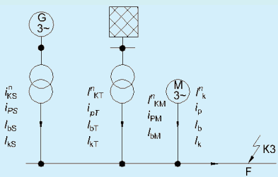
Fig. 6 Example of a Non-Meshed Network
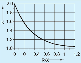
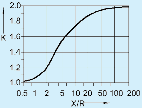
Fig. 7 Factor K for Series Circuit As a Function of Ration R/X or X/R
where I2 dt is the thermal stress ( A 2 s )
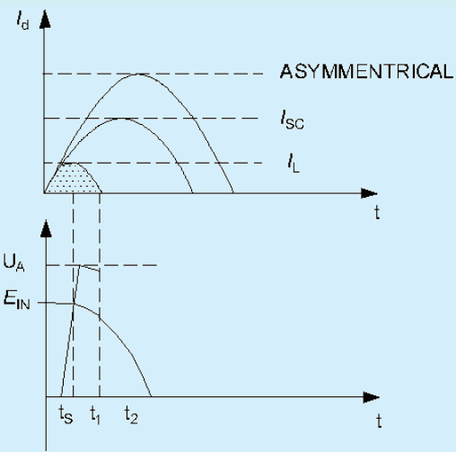
Fig. A-3 Effect Of Limitation On Fault Current
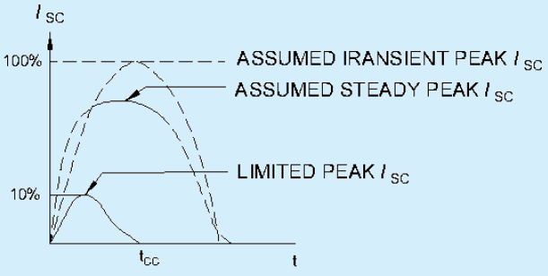
Fig. A-4 Current Limitation
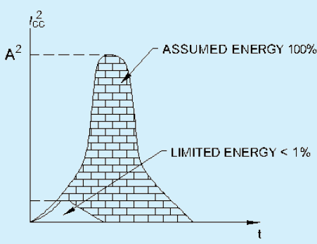
Fig. A-5 Thermal Stress Limitation
Limitation considerably, attenuates the harmful effects of short-circuits on the installation. Consequently, limitation contributes to the durability of electrical installations. Due to limitation, the harmful effects of short-circuits on a motor feeder are greatly attenuated. Proper limitation ensures easy access to a Type 2 coordination as per IS/ IEC 60947-4-1, without oversizing of components. This type of coordination ensures optimum use of their motor feeders.
| Copper ρ = (1)/(54) Ω mm2m; Aluminium ρ = (1)/(34) Ω mm2m; Aluminium alloy ρ = (1)/(31) Ω mm2mq<sub>n</sub>- Nominal cross sectional areaρ- Resistivityd - √[3]d<sub>L1L2</sub> d<sub>L2L3</sub> d<sub>L3L1</sub> geometric mean distance between conductors, or the centre of bundles;r- is the radius of a single conductor. In the case of conductor bundles, r is to be substituted by r<sub>B</sub> = √[n]nrRⁿ⁻¹, where R is the bundle radius (see IEC 60909-2);n- is the number of bundled conductors; for single conductors n=1;µ₀ - 4π × 10⁻⁷ H/m. |
| --- | --- | --- |
| Synchronous generators (Motors with voltage regulator) | Z GK = K G Z G = K G ( R G + jX d′ ′ )K G = U nU rG · c 1 + x d′ ′ rG | U rG- the rated voltage of the generator;Z GK- the corrected subtransient impedance of the generator;Z G- the subtransient impedance in the positive-sequence system: Z G = R G + jX d′ rG- the phase angle between IrG and U<sub>rG</sub> / √(3)x<sub>d</sub><sup>′ ′</sup>- the relative subtransient reactance of the generator related to the rated impedance:x<sub>d</sub><sup>′</sup> = x<sub>d</sub><sup>′</sup> / Z<sub>rG</sub> where Z<sub>rG</sub> = U<sub>rG</sub>² / S<sub>rG</sub>The fictitious resistances R<sub>Gf</sub> may be used for the calculation of the peak shortcircuit current with sufficient accuracyR<sub>Gf</sub> = 0.05 X<sub>d</sub><sup>′ ′</sup> for generators with U<sub>rG</sub> > 1 kV and S<sub>rG</sub> ≥ 100 MVAR<sub>Gf</sub> = 0.07 X<sub>d</sub><sup>′ ′</sup> for generators with U<sub>rG</sub> > 1 kV and S\_{\mathrm{rG}} < 100 \mathrm{MVA}$$R\_{\mathrm{Gf}} = 0.15 X\_{\mathrm{d}}^{\prime \prime} for generators with U<sub>rG</sub> ≤ 1000 V |
Bending stress caused by the forces between sub-conductor is given by:
The dynamic force F d shall be calculated from:
Where,
a) F m and F s are Forces according to equation (9);
b) Z and Z s are section modulus of main and sub conductor;
c) V σ V r and V o s V r s V F are factor which take into account the dynamic phenomena referred from Table 3 ; and
d) β and α are factor depending on type and number of supports taken from Table 4.
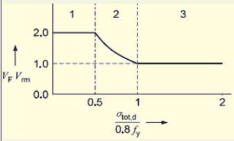
| Table 3 (Concluded) | |||||
| Three-phase | 1.0 | 1.0 | 1.8 | 2.7 for σ tot,d0.8fy ≤ 0.37 | range1 |
| 0.8fyσ tot,d for 0.37 < σ tot,d0.8fy < 1.0 | 2 | ||||
| 1.0 for 1.0 ≤ σ tot,d0.8fy | 3 | ||||
| Type of Beam and Support | α | β*) | γ | ||
| Single span beam | A and B: simple supports | A: 0.5 B: 0.5 | 1.0 | 1.57 | |
| A: fixed support B: simple support | A: 0.625 B: 0.375 | 181=0.73 | 2.45 | ||
| A and B: fixed supports | A: 0.5 B: 0.5 | 186 =0.5 | 3.56 | ||
| Continuous beam with equidistant simple supports | Two spans | A: 0.375 B: 1.25 | 181=0.73 | 2.45 | |
| Three or more spans | A: 0.4 B: 1.1 | 181=0.73 | 3.56 | ||
| * Plasticity effects included. | |||||
The thermal equivalent short-circuit current is to be calculated using the short-circuit current rms value and the factors m and n for the time-dependent heat effects of the dc and ac components of the short-circuit current.
SP 30 : 2023
The thermal equivalent short-circuit current can be expressed by:
Where,
a) m and n are numerical factors, and
b) I k '' the rms value of the initial symmetrical short-circuit current.
In a three-phase system, the balanced three-phase short circuit is decisive. The values m and n are usually defined as functions of the duration of the short-circuit current. For a distribution network usually n = 1
NOTE — The relation I k / I k is dependent on the impedance between the short-circuit and the source.
When a number of short-circuits occur with a short time interval in between, the resulting thermal equivalent short-circuit current is obtained from:
and
The temperature rise in a conductor caused by a short-circuit is a function of the duration of the short-circuit current, the thermal equivalent short-circuit current and the conductor material.
NOTE — The maximum permitted temperature of the support has to be taken into account.
4.2.2.4 Calculation of the thermal short-circuit strength for different durations of the short-circuit current
Electrical equipment has sufficient thermal short- circuit strength as long as the following relations hold for the thermal equivalent short-circuit current I t h ;
where I t h r is the rated short-time current and T k r the rated short-time.
The thermal short-circuit strength for a bare conductor is sufficient when the thermal equivalent short-circuit current density S t h satisfies the following relation:
With T k r = 1 s and for all T k ° the rated short time current density S t h r is shown in Fig. 4.
Below equation shall be used instead of equation (18):
Where
a) I t h shall be taken from equation (13) or (14)
b) T k shall be taken from equation (15)
For three-phase circuits the calculated mV/A/m values relate to the line voltage and balanced conditions have to be assumed.
The direct use of the calculated resistive component (mV/A/m)R or reactive component (mV/A/m)X or (mV/A/m)Z impedance values, as appropriate, may lead to pessimistically high calculated values of voltage drop or in other words, to unnecessarily low values of permitted circuit lengths.
Where the design current of a circuit is significantly less than the effective current-carrying capacity of the cable chosen, the actual voltage drop would be less than the calculated value because the conductor temperature (and its resistance) will be less than that on which the calculated mV/A/m had been based.
In some cases, it may be advantageous to take account of the load power factor while calculating voltage drop.
Voltage drops may be determined using the following formula:
Where,
a) u is the voltage drop in volts;
b) b is the coefficient equal to 1 for three-phases circuits, and equal to 2 for single-phase circuits;
NOTE — Three-phase circuits with the neutral completely unbalanced are considered a single-phase circuits.
c) p 1 is the resistivity of conductors in normal service, taken equal to the resistivity at the temperature in normal service, that is, 1.25 times the resistivity at 2 0 ° C i or 0.022 5 Ω mm2/m for copper and 0.036 Ω mm2/m for aluminum;
d) L is the straight length of the wiring systems, in meters;
e) S is the cross-sectional area of conductors, mm²;
f) cos φ is the power factor; in the absence of precise details, the power factor is taken as equal to 0.8 (sin = 0 . 6 ) ;
g) λ is the reactance per unit length of conductors, which is taken to be 0.08 mΩ/m in the absence of other details; and
h) I ~ B is the design current (in amps).
The relevant voltage drop in per cent is equal to:
NATIONAL ELECTRICAL CODE OF INDIA
U 0 is the voltage between line and neutral, in volts.
SP 30 : 2023
For cables having conductors of cross-sectional area 16 mm² or less the design value of mV/A/m is obtained by multiplying the calculated value by a factor C t and is, given by:
Where,
t p = maximum permitted normal operating temperature, in ° C ,
NOTE — For convenience, the above formula is based on the resistance-temperature coefficient of 0.004 per °C at 20°C for both copper and aluminum conductors.
For very large conductor sizes where the resistive component of voltage drop is much less than the corresponding reactive part (that is when x / r ≥ 3 ) this correction factor need not be considered.
For cables with conductors’ cross-sectional area of 16 mm² or less the design value of mV/A/m is obtained approximately by multiplying the calculated value by the power factor of the load (cos φ).
For cables with conductors’ cross-sectional area greater than 16 mm², the design value of m/V/A/m is approximately:
For single-core cables in flat formation the calculated values apply to the outer cables and may underestimate for the voltage drop between an outer cable and the center cable for cross-sectional areas above 240 mm² and power factors greater than 0.8.
Where it is considered appropriate to correct the calculated mV/A/m value for both operating temperature and load power factor, the design values of mV/A/m are given by:
a) for cable having conductors of 16 mm² or less cross-sectional area:
C t cos (Calculated mV/A/m)
b) for cables having conductors of cross-sectional area greater than 16 mm²:
C t cos φ (Calculated mV/A/m) ) + sin φ
In case of air-conditioning plants where re-heating is used, a safety device shall be incorporated in the installation to cut off automatically the source of heating, by means of some device, as soon as the temperature reaches a predetermined high level.
6.3.3 In case of air-conditioning plants where heating by means of an electric heater designed to operate in an air current, a safety device shall be incorporated in the installation to cut off the supply of electricity to the heating device whenever there is failure of the air current in which the heater is required to operate. Serious harm to the plant and sometimes fires may be caused by negligence in this respect.
6.3.4 Air-conditioning and ventilating systems circulating air to more than one floor or fire area shall be provided with dampers designed to close automatically in case of fire and thereby prevent spread of fire or smoke. Such system shall also be provided with automatic controls to stop fans in case of fire, unless arranged to remove smoke from a fire, in which case these shall be designed to remain in operation.
6.3.5 Air-conditioning system serving large places of assembly (over 1 000 persons), large departmental stores or hotels with over 100 rooms in a single block shall be provided with effective means for preventing circulation of smoke through the system in case of a fire in air filters or from other sources drawn into the system even though there is insufficient heat to actuate heat sensitive devices controlling fans or dampers. Such means shall consist of suitable photo-electric or other effective smoke sensitive controls, or may be manually operated control
Air conditioning being major guzzler of electricity involving huge running cost, needs precise design and selection of equipment. For human comfort, 24°C temperature is considered as standard as per ASHRAE. However, considering average range of maximum to minimum temperature in Indian tropical region setting upper limits will not affect comfort. Considerable power saving can be achieved with setting the temperature at 1° higher.
Based on Energy Efficiency, Bureau of Energy Efficiency (BEE) issues star rating, from 1 star to 5 stars. A unit with 5 stars has maximum energy efficiency. It is denoted by EER (Energy Efficiency Ratio). EER is mentioned as ratio in W/W that is heat removed in watts (3412 BTU = 1 kW/hr) to power used in watts within that hour. For EER, fixed parameters are considered as base. As per recent modification ISEER (Indian Seasonal Energy Efficiency Ratio) is considered, which is more precise as it considers seasonal power consumption with the variation in temperatures in different seasons – summer and winter. Room air- conditioners are available as fixed speed and variable speed with Inverter technology. Efficiency of Inverter type room air conditioners is very good as input power is precisely controlled as per actual requirement.
Advanced technology with variable refrigerant flow (VRF) systems give very good results in reducing electricity bills.
In major systems having central plant, location of various equipment like compressors/chillers, AHUs, allied piping and ducting design, lengths and cross section aspect ratio (perimeter: cross section ratio) play important role in deciding efficiency of the system. Selection of proper compressor and drives contribute towards power saving.
These systems help to conserve energy and reduce heating/cooling demands. Scope shall be checked from the experts.
Such system utilizes power in off-peak period to create chilled product under low tariff (energy charges) zone of the day. This thermal storage is utilized in peak demand period reducing resultant aggregate demand and give good savings.
be sensitive for sinusoidal currents up to 1 000 Hz, insensitive for currents more than 1 000 Hz. NOTE — These kinds of RCDs are generally classified as ‘Type B’.
never be protected with a 30 mA residual current device (RCD). The 30 mA RCD may trip when the lift starts and stall the operation. If the construction-time power supply is for some reason protected with a 30 mA residual current device (RCD), suitably sized isolation transformer needs to be provided.
All the lines are collected in the main distribution board. The main distribution board should be located in the same part of the building in the immediate vicinity of the telephone equipment. If the telephone equipment extends over several buildings, each building is connected to the main distribution board by a main cable.
The floor distribution boards should be accommodated close to the stair well. The rising mains are run vertically to the floors.
9.8.8.1 At the positions allocated for the telephones, the conduit should be terminated in flush-type boxes. For junction boxes and socket outlets for the connection of telephones, flush-type boxes (switch boxes) to standards are adequate. A maximum of two telephones can be connected to a junction box.
9.8.8.2 In most cases, the telephone is connected permanently to the subscriber’s line through a junction box. If it is required to be able to use it in a number of rooms, socket outlets and plugs should be provided. Units for flush and surface mounting are available for both methods of connection.
Preventive fire precautions (for example, fireproof barriers) should be considered at an early stage of planning.
The completed installation shall be inspected and simulation testing shall be performed to ensure that all the designed functions are available as per the standards and norms of specified by the manufacturer.
In case of failure of power from main supply, there shall be provision of Generator set powering fire-fighting system. Generator set shall be of adequate capacity to bear starting load of motors.
13.3.3.3 It is important to note that electric supply and distribution layouts, routes of cables, location of pump room and control panels shall be so designed that under fire situation, supply to the fire-fighting equipment remains uninterrupted.
13.3.3.4 All motors and electrical equipment shall be continuously rated, drip-proof with air inlets and outlets, and protected with meshed wire panels.
13.3.3.5 The starting equipment of the set shall incorporate an ammeter to clearly indicate full load current. It shall not incorporate no-volt trips.
13.3.3.6 Protective measures as defined in IS 1646 shall be applied to fire fighting system..
3.6 All electrical equipment likely to cause high temperatures or electric arcs shall be placed or guarded so as to eliminate the risk of ignition of flammable materials. A proper shielding/barricading should be provided around such equipment/‘vicinity containing such equipment’ to avoid transfer of excess heat (till flash point) through any possible means. Where the temperature of any exposed parts of electrical equipment is likely to cause injury to persons, these parts shall be so located as to prevent accidental contact therewith. Appropriate personnel with suitable protective gear shall be deployed within such vicinities. In case the work execution is in close vicinity of live electric conductor, the protection gear should be of sufficient capability to avoid any transfer of electricity directly/residually or through leakage to human body. All safety provisions specified in The Electricity Act, 2003 and CEA regulations must be followed during erection of equipment.
3.7 Several Indian Standards exist on installation of specific electrical equipment. These shall be adhered to during erection of the installation.
d) Suitable linked switch or circuit-breaker or lockable push button shall be provided near the motors/ apparatus for controlling supply to the motor apparatus at an accessible location;
e) Control switchgear shall be provided at an accessible height from ground for controlling supply to overhead travelling crane hoists and overhead bus bar trunking;
f) The metal rails on which the crane travels are electrically continuous, earthed and bonded at both ends;
g) Trailing cables of three cores(with one earthing core) should be used for single phase overhead travelling cranes and portable equipment and six core trailing cables should be used in case of three phase loads, 5th core is used for protective earthing and 6th core for functional earthing;
h) If flexible metallic hose is used for wiring to motors and equipment, full length of wiring shall be enclosed, and the hose shall be secured properly using end coupling;
j) The cables shall not be laid in areas which may damage due to mechanical impact or environmental influence;
k) The screens and armour of the cables shall be connected to earthing system properly;
m) The belts of the belt driven equipment shall be properly guarded;
n) Ammeters and voltmeters shall be tested and calibrated;
p) Relays shall be inspected visually for deposits or dusts or other foreign matter and their operations and accuracies should be checked using suitable primary/secondary injection equipment;
q) Flat washers backed up by spring washers shall be used for making end connections; and
r) Number of wires in a conduit shall conform to provisions of this Code.
Where,
R i = insulation resistance in MΩ at 2 5 ° C ,
E n = rated phase-to-phase voltage, and
P = rated power kW.
If the resistance is measured at a temperature different from 2 5 ° C 1 the value shall be corrected to 2 5 ° C
b) The insulation resistance as measured at ambient temperature does not always give a reliable value, since moisture might have been absorbed during shipment and storage. When the temperature of such a motor is raised, the insulation resistance will initially drop considerably, even below the acceptable minimum. In case of any doubt under such circumstances, motor winding shall be dried out.
| Rated current.....A |
| TN-C-S | 2-phase □ 3-pole □3-wire | Prospective fault current, Ipf⁽²⁾ ...kAExternal loop impedance, Ze⁽²⁾ ...Ω(Note: (1) by enquiry,(2) by enquiry, calculation or measurement) |
| TT | 3-phase □ other □3-wire |
| IT | 3-phase □ other □4-wire |
| Confirmation of supply □polarity |
| Alternative source of supply (as detailed an attached schedule) |
| Section J. Particulars of installation referred to in report |
3.10 From the point of safety consideration, the objective is not to attain minimum value of the earth resistance but there shall be adequate co-ordination between the obtainable value of the earth fault loop and setting of the protective devices.