7.1 Design of an earthing system shall take into account the following:
a) data collection (for example, earth fault current, fault duration and layout);
b) initial design of the earthing system based on the functional requirements;
c) determine if it is part of a global earthing system;
d) if not part of global earthing system, determine soil characteristics (for example, specific soil resistivity of layers);
e) determine the current flowing into earth from the earthing system, based on earth fault current;
f) determine the overall impedance to earth, based on the layout, soil characteristics and parallel earthing systems;
g) determine earth potential rise;
h) determine permissible touch voltage; if the earth potential rise is below the permissible touch voltage and the requirements of Table 3 are fulfilled, the design is adequate;
j) if does not conforms to (h), determine if touch voltages inside and in the vicinity of the earthing system are below the tolerable limits;
k) determine if transferred potentials present a hazard outside or inside the electrical power installation and take suitable actions for mitigation at exposed location; and
m) determine if low-voltage equipment is exposed to excessive stress voltage and take measures for separation of HV and LV earthing systems.
7.2 On fulfilment of criteria as per 7.1, the design can be refined by repeating the above steps, if necessary. Detailed design is necessary to ensure that all exposed conductive parts, are earthed. Extraneous conductive parts shall be earthed, if appropriate.
NOTE — Flowchart of design process is given in Annex D.
7.3 The structural earth electrode shall be bonded and form part of the earthing system. If earth electrode is not bonded, all safety requirements shall be verfied. Metallic structures with cathodic protection may be separated from the earthing system. Precautions, such as labelling, shall be taken to prevent damage during maintenance work or modifications.
Table 3 Minimum Requirements for Interconnection of Low-voltage and High-voltage Earthing Systems Based on EPR Limits
(Clause 7.1 h)
| Sl No. | Type of LV System a,b | Touch Voltage | EPR Requirements | |
| Stress Voltagec | ||||
| Fault Duration tf < 5 s | Fault Duration tf > 5 s | |||
| (1) | (2) | (3) | (4) | (5) |
| i) | TT | Not applicable | EPR < 1200 V | EPR < 250 V |
| ii) | TN | EPR < F . UTPde | EPR < 1200 V | EPR < 250 V |
| a) For LV system, see IS 732. b) For telecommunication equipment, ITU recommendations shall be followed. c) Limit may be increased if appropriate LV equipment is installed or EPR may be replaced by local potential differences based on measurements or calculations. ( d) If the PEN or neutral conductor of the low-voltage system is connected to earth only at the HV earthing system, the value of F shall be 1. e) UTp is derived from Fig. 7 NOTE — The typical value for F is 2. Higher values of F may be applied where there are additional connections of the PEN conductor to earth. For certain soil structures, the value of F may be up to 5. The touch voltage can exceed 50 percent of the EPR where the top layer has higher resistivity. | ||||
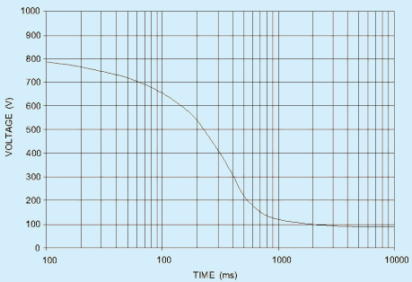
Fig. 7 Permissible Touch Voltage U T P
7.4 Protection of low-voltage installations against temporary over-voltages due to earth faults in the high-voltage system and due to faults in the low-voltage system shall be carried out as per 4.5.2 of IS 732.
ANNEX A (Clauses 3,4.11 and 4.23)
EXAMPLE OF EARTHING ARRANGEMENTS AND PROTECTIVE CONDUCTORS
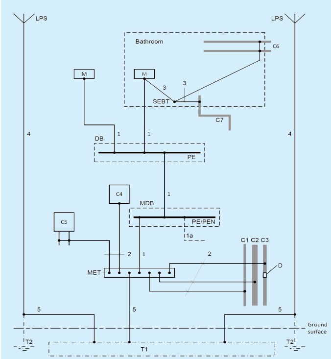
Key
| C | Extraneous-Conductive-part |
|---|---|
| C1 | Water pipe, metal from outside |
| C2 | Waste water pipe, metal from outside |
| C3 | Gas pipe with insulating insert, metal from outside |
| C4 | Air-conditioning |
| C5 | Heating system |
| C6 | Water pipe, metal for example, in a bathroom |
|---|---|
| C7 | Waste water pipe, metal for example, in a room |
| MDB | Main Distribution Board |
| DB | Distribution Board |
| MET | Main Earth Terminal |
| SEBT | Supplementary Equipotential Bonding terminal |
| T1 | Concrete-embedded foundation earth electrode or soil-embedded foundation earth electrode |
| T2 | Earth electrode for LPS if necessary |
| LPS | Lightning Protection system (if any) |
| PE | PE terminal(s) in the distribution board |
| PE/PEN | PE/PEN terminal(s) in the main distribution board |
| M | Exposed-conductive part |
| 1 | Protective Earthing conductor (PE) |
| 1a | Protective Conductor, or PEN conductor, if any, from supplying network |
| 2 | Protective bonding conductor for connection to the main earthing terminal |
| 3 | Protective bonding conductor for supplementary bonding |
| 4 | Down conductor of a lightning protection system (LPS) if any |
| 5 | Earthing conductor |
Fig. A-1 Examples of Earthing Arrangements for Foundation Earth Electrode, Protective Conductors and Protective Bonding Conductor