5.1 Earthing system above 230 V should be designed as a PME system with separate protective conductor (TN-S). Protective multiple earthing system shall be implemented to reduce the earth fault loop impedance and to ensure reliable disconnection of supply during an earth fault by the OCPD. In PME system, neutral of the supply transformer and the non-current carrying metal parts in the system are interconnected by the common earth grid, in addition to the separate protective conductor.
5.2 Hence, IS 3043, recommend TN-S system with PME, where the neutral of the source and exposed conductive parts in the installation are solidly connected to the MET and an earthing grid. In this interconnected system, earth fault current is returned to the neutral, through the interconnected system consisting of the PE conductor and earth grid.
5.3 The disposition of the earth electrodes and the extent and size of earth grid depends upon the disposition of plant electrics. The layout shall ensure that earth continuity resistance is within the acceptable range. Depending upon the disposition of the plant electrics, an optimum number of earth electrodes shall be provided as anchorages for the earth grid.
5.4 Protective Earth (PE) conductor shall run in parallel and proximity to line conductors
5.5 The continuity resistance of the earth return path through the earth grid shall be less than one ohm.
5.6 In case of EHT substations, where ground potential may attain very high values (of the order of 5 kV and above) in the event of an earth fault. The earth grid design shall be based on the acceptable limits of the potential gradient, step and touch potential in the substation area.
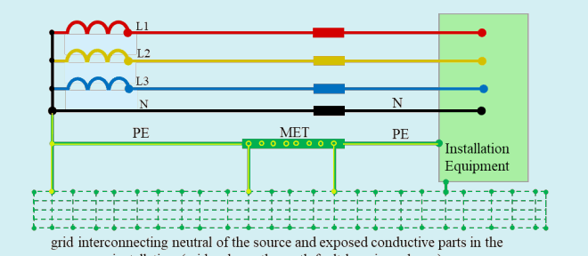
grid interconnecting neutral of the source and exposed conductive parts in the installation (grid reduces the earth fault loop impedance)
Fig. 3 System with Separate Earth Conductor (TN-S) Protective Multiple Earthing (PME)