This section of the code (Part 1/Sec 1) describes the scope of the National Electrical Code of India.
Loading…
Electricity has become an integral and inevitable part of everyone’s life. The progress and technological advancement of modern society depends on electricity. However it is important to remember that, if electrical installations are not handled according to relevant guidelines, it could be harmful. Therefore, electrical installations require adequate planning right from concept stage to layout and designing, selection of proper equipment, their installation and their maintenance. Fundamental aspects of installation practice are common for most of the types of electrical installations. Part 1 of the National Electrical Code of India covers these aspects under its various Sections.
There are several Indian Standards existing on different aspects of electrical installation practice. An attempt has been made through this Code to refer to the present good practices and guidelines. A reference has also been made to product standards in order to inform the user of the Code about the availability and desirability to use them.
Aspects concerning specific occupancies are covered in other Parts and Sections of this Code. The fundamental principles of installation practice covered under Part 1 of this Code generally apply, unless modified or supplemented by subsequent Parts. This Part 1 would also be a useful reference for occupancies not explicitly covered by the scope of subsequent Parts of the Code.
Scope of the National Electrical Code of India
Each Part/Section of the National Electrical Code of India covers the requirements related to electrical installations in specific occupancies. The fundamental and general principles governing electrical installation practice together with common aspects applicable to all types of installations has been brought out in a separate Part in order to serve as a reference document.
Effort has been made to make this part self-contained, so that users of the Code can derive utmost advantage in using it for application in the field even for occupancies not explicitly covered by the scope of subsequent Parts of the Code. Efforts have also been made to ensure that all the relevant details required for the understanding of the Code are available to the extent possible within Part 1 and effort has been made to keep the references of individual standards to the minimum.
The details enumerated in this Part are generally applicable to all types of occupancies and are to be read as modified or supplemented with the information provided in the relevant Parts of the Code.
The National Electrical Code of India takes into account the stipulations in several Indian Standards dealing with the various aspects related to electrical installation practices. Several product standards also exist, and compliance with relevant Indian Standards is desirable. It is therefore recommended that individual Parts/Sections of the Code should be read in conjunction with the relevant Indian Standards. List of such Indian Standards is given at relevant Part/Section of the Code.
At the time of publication, the editions indicated were valid. All standards are subject to revision, and parties to agreements based on this standard are encouraged to investigate the possibility of applying the most recent editions of the standards.
3.1.1 Arc — Luminous discharge of electricity across an insulating medium, usually, accompanied by the partial volatilization of the electrodes.
NOTE — A complete sinusoidal current half cycle is not considered to be an arcing half cycle.
3.1.2 Capacitor — Two terminal devices characterized, essentially, by its capacitance.
3.1.3 Conductor — Conductive part intendent to carry electric current.
3.1.4 Connection of Circuits
3.1.4.1 Series — Connections of two terminal networks so that they form a single path for current.
NOTE — An example of a series connection is series resonant circuit.
NOTE — All two terminal networks in a series connection carry the same current.
3.1.4.2 Parallel — Connections of two terminal networks so that they are connected to a common terminal pair. NOTES
1 An example of a parallel connection is parallel resonant circuit.
2 Same voltage is applied to all two terminal networks in a parallel connection.
3.1.5 Series Parallel — Series parallel connection (related to cells or batteries): Arrangement of cells or batteries wherein in series connected cells or batteries are connected in parallel.
3.1.6 Dielectric — A material medium in which an electric field can exist in a stationary state.
3.1.7 Earth Fault— Occurrence of an accidental conductive path between a live conductor and the earth or exposed conductive part of a protective conductor.
NOTES
1 The conductive path can pass through a faulty insulation, through structures (for example, poles scaffoldings, cranes, ladders) or through vegetation (for example, Tree, bushes) and can have a significant impedance.
2 Earth fault with negligible fault impedance in solidly earthed neutral system or in a low impedance earthed neutral system are also named line - to - earth short – circuits.
3.1.8 Earth Leakage Current — Current which flows to earth or to extraneous conductive parts in a circuit which is electrically sound.
3.1.9 Electric Circuit (or Circuit) — An assembly of electrical equipment supplied from the same origin and protected against over current by the same protective devices. Certain types of circuits are categorized as follows:
NOTE — Electric circuit is also defined as circuit consisting of electric circuit elements only.
a) Category 1 Circuit — Circuit (other than a fire alarm or emergency lighting circuit) operating at low voltage and supplied directly from a mains supply system.
b) Category 2 Circuit — With the exception of fire alarm and emergency lighting circuits, any circuit for telecommunication (for example, radio, telephone, sound distribution, intruder alarm, bell, call and data transmission circuits) which is supplied from a safety source.
c) Category 3 Circuit — A fire alarm circuit or an emergency lighting circuit.
3.1.10 Electric Current — Scalar quantity equal to the flux of the electric current density J through a given directed surface
where e dA is the vector surface element
NOTES
1 The electric current through a surface is equal to the limit of the quotient of the electric charge transferred through that surface during a time interval by the duration of this interval when this duration tends to zero.
2 For charge carriers confined to a surface, the electric current is defined through a curve of this surface (see the note to term “lineic electric current”).
3.1.11 Electrode — Conductive part in electric contact with a medium of lower conductivity and intended to perform one or more of the functions of emitting charge carriers to or receiving charge carriers from that medium or to establish an electric field in that medium.
3.1.12 Functional Extra-low Voltage (FELV) — extra-low voltage system in which not all of the protective measures required for SELV or PELV have been applied.
3.1.13 Flashover — Electrical breakdown between conductors in air, a gas or a liquid or in vacuum, at-least partly, along the surface of a solid insulation.
3.1.14 Insulation Fault — in the insulation of an equipment, wire or cable which can result either in an abnormal electric current through this insulation or in a disruptive discharge.
3.1.15 Overload — Operating conditions in an electrically undamaged circuit which causes an overcurrent.
3.1.16 PELV (Protective Extra-low Voltage) — extra-low voltage system which is not electrically separated from earth, but which otherwise satisfies all the requirements for SELV.
3.1.17 SELV (Separated Extra Low-Voltage) — An extra low-voltage system which is electrically separated from earth and from other system in such a way that a single fault cannot give rise to the risk of electric shock.
7
3.1.18 Short-circuit — Accidental or intentional conductive path between two or more conductive parts forcing the electric potential differences between these conductive parts to be equal to or close to zero.
3.1.19 Spark — Small luminous electric arc of short duration.
3.1.20 Voltage, Potential Difference — The line of integral from one point to another of an electric field, taken along a given path.
3.1.21 Voltage Classifications — Nomenclature of commonly used short names of voltages
3.1.23.1 ELV (extra low voltage) — A system with a nominal voltage Un ≤ 50 V a.c. or ≤ 120 V d.c.;
3.1.23.2 LV (low voltage) — A system with a nominal voltage Un ≤ 1 000 V a.c. and ≤ 1 500 V d.c.
3.1.23.3 MV (medium voltage) — A system with a nominal rms voltage is 1 kW < U n ≤ 33 kW
3.1.23.4 HV (high voltage) — A system with a nominal rms voltage is 3 3 < U n ≤ 1 5 0 k V .
3.1.23.5 EHV (extra high voltage) — A system with a nominal rms voltage is > 150 kV. NOTES
1 The above nomenclatures are adopted from IS 17036 and IS 732 for the purpose of this code.
Each Part and section of the Code gives, where necessary, definitions of terms and phrases relevant for the comprehension of the requirements stipulated therein. Users may find it convenient to refer to a detailed list of terms and their definitions contained in this section that are relevant to electrical installation practices. It may, however, be noted that for further guidance, recourse should be made to IS 1885 (series of standards) and IEC 60050 on electrotechnical vocabulary containing a compendium of terms in the field.
The definitions contained in the Code are based on the current international terminology as far as possible. Some definitions are based on the terminology drawn up by the relevant expert groups under the Electrotechnical Division Council with the objective of striking a correct balance between absolute precision and simplicity. The principal objective of this exercise is to provide definitions which are sufficiently clear so that each term is understood with the same meaning by all concerned. It may, sometimes, be felt that the definitions are not identical with those which may be found in other publications designed with different objectives and for other readers. Such differences are inevitable and should be accepted in the interest of clarity.
This section of the code (Part 1/Sec 2) covers definitions of terms.
The standards listed in Annex A contain provisions, which through reference in this text, constitute provisions of this standard. At the time of publication, the editions indicated were valid. All standards are subject to revision, and parties to agreements based on this standard are encouraged to investigate the possibility of applying the most recent editions of the standards.
For the purpose of the National Electrical Code of India, the following definitions shall apply, in addition to those contained in individual Parts/Sections and relevant Indian Standards.
a) Standard good practices for selection of various items of electrical equipment forming part of electrical installation;
b) Recommendations concerning safety and quality of the wiring in electrical installations of buildings or industrial structures, promoting compatibility between such recommendations and those concerning the equipment installed;
c) General safety procedures and practices in electrical work; and
d) Additional precautions to be taken for use of electrical equipment for special environmental conditions like explosive and active atmosphere.
3.2 The Code applies to electrical installations, such as those in:
a) Standby/emergency generating plants and building substations;
b) Domestic dwellings;
c) Office buildings, shopping and commercial centres and institutions;
d) Recreation and other public premises;
e) Medical locations;
f) Hotels;
g) Swimming pools;
h) Rooms containing sauna heaters;
j) Multi-storied buildings;
k) Supplies for electrical vehicles;
SP 30 : 2023
m) Sports buildings;
n) Industrial and non-industrial premises;
p) Temporary and permanent outdoor installations;
q) Agricultural premises;
r) Installations in hazardous areas; and
s) Solar photovoltaic installations.
NOTES
1 Any type of installation not covered by the above shall be classified in the group which most nearly resemble its existing or proposed use.
2 Where change in the occupancy places it under the scope of a different Section of the Code, the same installation shall be made to comply with the requirements of the Code for the new occupancy.
3 While numbering above items, ‘i’ and ‘o’ are avoided to avoid confusion with numerals ‘1’ and ‘0’.
3.3 The Code applies to circuits other than the internal wiring of apparatus.
3.4 The Code does not apply to traction, motor vehicles and installations in rolling-stock, on board-ships, aircraft or installations in underground mines.
3.5 The Code covers only electrical aspects of lightning protection of buildings.
3.2.1 Apparatus — Device or assembly of devices which can be used as an independent unit for specific functions.
3.2.2 Appliance — apparatus intended for household or similar use.
3.2.3 Auto-transformer — A transformer in which at least two windings have a common part.
3.2.4 Bimetallic-Connector — Connector formed by two different metals metallurgically bonded, used to connect conducting parts consisting of these same metals.
3.2.5 Circuit-Breaker (Mechanical) — A mechanical switching device capable of making, carrying and breaking currents under normal circuit conditions, and breaking currents under specified abnormal circuit conditions such as those of short circuit.
NOTE — A circuit breaker is usually intended to operate infrequently, although some types are suitable for frequent operation.
3.2.6 Circuit Breaker Linked — A circuit breaker, the contacts of which are so arranged as to make or break all poles simultaneously or in a definite sequence.
3.2.7 Class-I-Equipment — Equipment in which protection against electric shock does not rely on basic insulation only, but which includes an additional safety precaution in such a way that means are provided for the connection of exposed conductive parts to a protective conductor in the fixed wiring of installation in such a way that accessible conductive parts may not become live in the event of a failure of basic insulation.
NOTE — For information on classification of equipment with regard to means provided for protection against electric shock, see IEC 61140.
3.2.8 Class-II-Equipment — Equipment in which protection against electric shock does not rely on basic insulation only, but in which additional safety precautions, such as double or reinforced insulation are provided, there being no provision for the connection of exposed metal work of the equipment to a protective conductor, and no reliance upon precautions to be taken in the fixed wiring of the installation.
3.2.9 Class-III-Equipment — Equipment in which protection against electric shock relies on supply at SELV and in which voltages higher than those of SELV are not generated.
3.2.10 Current using Equipment — Equipment which converts electrical energy into another form of energy, such as light, heat, or motive power.
3.2.11 Disconnector — A mechanical switching device which provides, in the open position, an isolating distance in accordance with specified requirements.
NOTES
1 A disconnector is also known as isolator.
2 A disconnector is capable of opening and closing a circuit when either a negligible current is broken or made, or when no significant change in the voltage across the terminals of each pole of the disconnector occurs. It is also capable of carrying currents under normal circuit conditions and current under abnormal conditions such as those of short-circuit for a specified time.
3.3.1 Accessory — A device, other than current-using equipment, associated with such equipment or with the wiring of an installation.
3.3.2 Aerial Conductor — Any conductor which is supported by or suspended on insulators above the ground and is directly exposed to the weather.
NOTE — The following four classes of aerial conductors are recognized:
a) Bare aerial conductors;
b) Covered aerial conductors;
c) Insulated aerial conductors;
SP 30 : 2023
d) Weatherproof neutral-screened cable; and
e) Aerial bunched cable.
3.3.3 Back-up Protection — Protection which is intended to operate when a system fault is not cleared or abnormal condition not detected in the required time, because of failure or inability of other protection to operate or failure of appropriate circuit-breaker(s) to trip.
3.3.4 Barrier — A part providing a defined degree of protection against contact with live parts, from any usual direction of access.
3.3.5 Basic Insulation — Insulation of hazardous-live-parts which provides basic protection.
NOTE — This concept does not apply to insulation used exclusively for functional purposes.
3.3.6 Basic Protection — Protection against electric shock under fault-free condition.
3.3.7 Bonding Conductor — A protective conductor providing equipotential bonding.
3.3.8 Bonding Network (BN) — A set of interconnected conductive parts that provide a path for current at frequencies from direct current (d.c.) to radio frequency (RF) intended to divert, block or impede the passage of electromagnetic energy.
3.3.9 Bonding Ring Conductor (BRC) — A bus earthing conductor in the form of a closed ring.
NOTE — Normally the bonding ring conductor, as part of the bonding network, has multiple connections to the common bonding network (CBN) that improves its performance.
3.3.10 Bunched — Cables are said to be ‘bunched’ when two or more are contained within a single conduit, duct or groove or, if not enclosed, are not separated from each other.
3.3.11 Buried Direct — A cable laid in the ground in intimate contact with the soil.
3.3.12 Busbar Trunking System — A type-tested assembly, in the form of an enclosed conductor system comprising solid conductors separated by insulating materials. The assembly may consist of units such as:
a) Busbar trunking units, with or without tap-off facilities;
b) Tap-off units where applicable; and
3.4.1 Agricultural and Horticultural Premises — Rooms, location or areas where live stocks are kept and feed, fertilizers, vegetable and animal products are produced, stored, prepared or processed and plants are grown such as greenhouse.
3.4.2 Ambient Temperature — Average temperature of air or another medium in the vicinity of the equipment NOTE — During the measurement of the ambient temperature the measuring instrument/probe should be shielded from draughts and radiant heating.
3.4.3 Arm’s Reach — Either the distance measured from the floor to the fingertips of a person fully extended in the vertical direction or for any other direction at one-third of that distance.
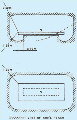
NOTE — This space is by convention, limited as shown in Fig. 1.
Fig. 1 Limit of Arm’s Reach
3.4.4 Barrier — A part providing protection against direct contact from any usual direction of access
3.4.5 Basin of Fountain — A basin not intended to be occupied by persons and which cannot be accessed (reached by persons) without the use of ladders or similar means. For basins of fountains which may be occupied by persons, the requirement of swimming pools applies.
3.4.6 Booth — Non-stationary unit intended to accommodate equipment generally for pleasure or demonstration purpose.
3.4.7 Building — Any structure for whatsoever purpose and of whatsoever materials constructed and every part thereof whether used as human habitation or not and includes foundation, plinth, walls, floors, roofs, chimneys, plumbing and building services, fixed platforms, verandah, balcony, cornice or projection, part of a building or anything affixed thereto or any wall enclosing or intended to enclose any land or space and signs and outdoor display structures. Tents, shamianahs, tarpaulin shelters, etc, erected for temporary of the Authority shall not be considered as building.
3.4.8 Building Voids, Accessible — Space within the structure or the components of a building accessible only at certain points.
NOTE — Examples are space within partitions, suspended floors, ceilings and certain types of window frames, door frames and architraves A specially formed building void in an element of building is also known as a duct.
3.4.9 Building Void, Non-accessible — A space within the structure or the components of building which has no ready means of access.
| IS No./International Standard | Title |
|---|---|
| 732 : 2019 | Code of practice for electrical wiring installations |
| 1885 (Part 1) : 1961 | Electrotechnical vocabulary — Part 1 Fundamental definitions |
| 1885 (Part 9) : 1992/IEC 60050-446 : 1983 | Electrotechnical vocabulary — Part 9 Electrical relays (second revision) |
| 1885 (Part 10) : 2008/IEC 60050 (448) : 1995 | Electrotechnical vocabulary — Part 10 Power system protection (second revision) |
| 1885 (Part 11) : 1966 | Electrotechnical vocabulary — Part 11 Electrical measurements |
| 1885 (Part 14) : 1967 | Electrotechnical vocabulary — Part 14 nuclear power plants |
| 1885 (Part 15) : 2008/IEC 60050-482 : 2004 | Electrotechnical vocabulary — Part 15 Primary and secondary cells and batteries (second revision) |
| 1885 (Part 16/Sec 1) : 1968/IEC 60050-45 : 1958 | Electrotechnical vocabulary — Part 16 Lighting — Section 1 General aspects |
| 1885 (Part 16/Sec 2) : 1968/IEC 60050-45 : 1958 | Electrotechnical vocabulary — Part 16 Lighting — Section 2 General illumination, lighting fittings and lighting for traffic and signalling |
| 1885 (Part 16/Sec 3) : 1967/IEC 60050-54 | Electrotechnical vocabulary — Part 16 Lighting — Section 3 Lamps and auxiliary apparatus |
| 1885 (Part 17) : 1979/IEC 60050-441 : 1974 | Electrotechnical vocabulary — Part 17 Switchgear and control gear (first revision) |
| 1885 (Part 27) : 2008/IEC 60050-551 : 1998 | Electrotechnical vocabulary — Part 27 Power electronics (third revision) |
| 1885 (Part 28) : 1993/IEC 60050-321 : 1986 | Electrotechnical vocabulary — Part 28 Instrument transformers (first revision) |
| 1885 (Part 29) : 1971 | Electrotechnical vocabulary — Part 29 Mining terms |
| 1885 (Part 30) : 1971 |
| IS/Other Publications | Title |
|---|---|
| 2032 (Part 19) : 1977 | Graphical symbols used in electrotechnology: Part 19 Electrical equipment used in medical practice |
| 3722 (Part 1) : 1983 | Letter symbols and signs used in electrical technology: Part 1 General guidance on symbols and subscripts (first revision) |
| 3722 (Part 2) : 1983 | Letter symbols and signs used in electrical technology: Part 2 Reference tables for symbols and subscripts (first revision) |
| 10381 : 1982 | Terms (and their hindi equivalents) commonly used for name — Plates and similar data of electrical power equipment |
| 11353 : 1985 | Guide for uniform system of marking and identification of conductors and apparatus terminals |
| 12032 (Part 1) : 1987/IEC 60617-1 (1985) | Graphical symbols for diagrams in the field of electrotechnology: Part 1 General information |
| 12032 (Part 2) : 1987/IEC 60617-2 (1983) | Graphical symbols for diagrams in the field of electrotechnology: Part 2 Symbol elements, qualifying symbols and other symbols having general application |
| 12032 (Part 3):1987/IEC 60617-3 : 1983 | Graphical symbols for diagrams in the field of electrotechnology: Part 3 conductors and connecting devices |
| 12032 (Part 4) : 1987/IEC 60617-4 (1984) | Graphical symbols for diagrams in the field of electrotechnology: Part 4 Passive components |
| 12032 (Part 6) : 1987/IEC 60617-6 (1983) | Graphical symbols for diagrams in the field of electrotechnology: Part 6 Production and conversion of electrical energy |
| 12032 (Part 7) : 1987/IEC 60617-7 (1983) | Graphical symbols for diagrams in the field of electrotechnology: Part 7 Switchgear, controlgear and protective devices |
| 12032 (Part 8) : 1987/IEC 60617-8 (1983) | Graphical symbols for diagrams in the field of electrotechnology: Part 8 Measuring instruments, lamps and signalling devices |
| 12032 (Part 11) : 1987/IEC 60617-11 (1983) |
| IS/Other Publications | Title |
|---|---|
| 1064 : 1980 | Specification for paper (second revision) |
| 2032 (Part 15) : 1976 | Graphical symbols used in electrotechnology — Part 15 Aircraft electrical symbols |
| 2032 (Part 19) : 1977 | Graphical symbols used in electrotechnology — Part 19 Electrical equipment used in medical practice |
| 2032 (Part 25) : 1980 | Graphical symbols used in electrotechnology — Part 25 Electrical installations in ships |
| 5578 : 1984 | Guide for marking of insulated conductors (first revision) |
| 8270 (Part 1) : 1976 | Guide for preparation of diagrams, charts and tables for electrotechnology — Part 1 Definitions and classification |
| 8270 (Part 2) : 1976 | Guide — For preparation of diagrams, charts and tables for electrotechnology — Part 2 Item designation |
| 8270 (Part 3) : 1977 | Guide for preparation of diagrams, charts and tables for electrotechnology — Part 3 General requirements for diagrams |
| 8270 (Part 4) : 1977 | Guide for preparation of diagrams, charts and tables for electrotechnology — Part 4 Circuit diagrams |
| 8270 (Part 5) : 1976 | Guide for preparation of diagrams, charts and tables for electrotechnology — Part 5 Interconnection diagrams and tables |
| 8270 (Part 6) : 1983 | Guide for preparation of diagrams, charts and tables for electrotechnology — Part 6 Unit wiring diagrams and tables |
| 11353 : 1985 | Guide for uniform system of marking and identification of conductors and apparatus terminals |
| IEC 60417 DB | Graphical symbols for use on equipment |
| IEC 81346-1 : 2009 | Industrial systems, installations and equipment and industrial products — Structuring principles and reference designations — Part 1 Basic rules |
| IEC 81346-2 : 2019 | Industrial systems, installations and equipment and industrial products — Structuring principles and reference designations — Part 2 Classification of objects and codes for classes |
2 Regulatory commissions of state governments use different definitions, which are not considered in this code
3.6 The Code is also not intended to apply to:
a) Systems of distribution of energy to public; and
b) Power generation and transmission for such systems.
3.7 The Code also does not cover guidelines on the payment for electrical work done in installations.
4 Central Electricity Authority Regulations under regulation 12 (2) of Central electricity authority (Measures relating to safety and electric supply) Regulations, 2010 recommends the National Electrical code of India as a code to be followed.
NOTE — In the event of any inconsistency, the provisions of the regulations shall prevail.
3.2.12 Electrical Equipment (Equipment) — Any item used for such purposes as generation, conversion, transmission, distribution or utilization of electric energy, such as electric machines, transformers, switchgear and control gear, measuring instruments, protective devices, wiring systems, current-using equipment.
3.2.13 Electric Motor — A machine which converts electrical energy into mechanical energy.
3.2.14 Electrode Boiler (or Electrode Water Heater) — Electric boiler used for heating water due to flow of alternating electric current through water between electrodes.
3.2.15 Enclosed Fuse-link — Fuse-link in which the fuse-element(s) is (are) totally enclosed, so that during operation within its rating it cannot produce any harmful external effects, for example, due to development of an arc, the release of gas or the ejection of flame or metallic particles.
SP 30 : 2023
3.2.16 Fixed Equipment — Electric equipment fastened to a support or otherwise secured in a specific location
3.2.17 Fuse — A device which, by fusing of one or more of its specially designed and proportioned components, opens the circuit in which it is inserted by breaking the current when this exceeds a given value for a sufficient time. The fuse comprises all the parts that form the complete device.
3.2.18 Fuse-base (Fuse-mount) — The fixed part of a fuse provided with contacts and terminals for connection to the system. The fuse-base comprises all the parts necessary for insulation.
3.2.19 Fuse-carrier — The movable part of a fuse designed to carry a fuse link.
3.2.20 Fuse-element — A part of the fuse-link designed to melt under the action of current exceeding some definite value for a definite period of time.
3.2.21 Fuse-link — A part of fuse, including the fuse element(s), which requires replacement by a new or renewable fuse link after the fuse has operated.
3.2.22 Fuse-switch — A switch in which a fuse-link or a fuse-carrier with fuse-link forms the moving contact.
3.2.23 Generator — A machine for converting mechanical energy into electrical energy.
3.2.24 Hand-held Equipment — Electric equipment intended to be held in the hand during normal use.
3.2.25 Induction Motor — An alternating current motor without a commutator in which one part only, the rotor or a stator, is connected to the supply network, the other working by induction.
3.2.26 Interconnecting Bus-bar — A conductor other than cable, used for external connection between terminals of equipment.
3.2.27 Lightning Arrester (Surge Diverter) — A device which has the property of diverting to earth any electrical surges of excessively high amplitude applied to its terminals and is capable of interrupting flow of current if present and restoring itself thereafter to its original operating condition.
3.2.28 Low-voltage Switchgear and Control gear Assembly — A combination of one or more low voltage switching devices together with associated control, measuring, signaling, protective, regulating equipment etc., completely assembled under the responsibility of the manufacturer with all the internal electrical and mechanical inter-connections and structural parts. The components of the assembly may be electromechanical or electronic
3.2.29 Luminaire — Apparatus which distributes, filters or transforms the light transmitted from one or more lamps and which includes, except the lamps themselves, all the parts necessary for fixing and protecting the lamps and, where necessary, circuit auxiliaries together with the means for connecting them to the electric supply.
NOTE — The term lighting fitting is deprecated.
3.2.30 Luminaire Supporting Coupler (LSC) — A means comprises of LSC outlet and an LSC connector, providing mechanical support for a luminaire and the electrical connection to and disconnection from a fixed wiring installation.
3.2.31 Miniature Circuit-breaker — A compact mechanical device for making, carrying and breaking a circuit both in normal conditions and also making, carrying for a specified duration and breaking currents under specified abnormal circuit conditions such as those of short circuit.
3.2.32 Mobile Equipment — Electrical equipment which is moved while in operation or which can be easily moved from one place to another while connected to the supply.
3.2.33 Motor Generator Set — Set which consists of one or more motors mechanically coupled to one or more generators.
3.2.34 Plug — Accessory having pins designed to engage with the contacts of a socket-outlet, also incorporating means for the electrical connection and mechanical retention of flexible cables or cords.
3.2.34.1.1 Portable Equipment — Equipment intended to be carried by a person during its operation.
NOTE — Portable equipment carried by a person during its operation is sometimes referred to as hand-held equipment.
3.2.35 Relay (Electric Relay) — Device designed to produce sudden predetermined changes in one or more electric output circuits, when certain conditions are fulfilled in the electric input circuits controlling the device.
3.2.36 Residual Current Device (RCD) — Mechanical switching device or association of devices designed to make, carry and break currents under normal service conditions and to cause the opening of the contacts when the residual current attains a given value under specified conditions.
3.2.37 Residual Current Operated Circuit-Breaker with Integral Overcurrent Protection (RCBO) — Residual current operated circuit-breaker designed to perform the functions of protection against overloads and/or short circuits.
3.2.38 Residual Current Operated Circuit-breaker without Integral Overcurrent Protection (RCCB) — Residual current operated circuit-breaker not designed to perform the functions of protection against overloads and/or short circuits.
3.2.39 Stationary Equipment — Fixed equipment or equipment not provided with a carrying handle and having such a mass that it cannot easily be moved.
NOTE — The value of this mass is 18 kg in IEC standards relating to household appliances
3.2.40 Switch — A mechanical switching device capable of making, carrying and breaking current under normal circuit conditions, which may include specified operating overload conditions, and also of carrying for a specified time currents under specified abnormal circuit conditions such as those of short circuit.
NOTE — A switch may also be capable of making, but not breaking, short-circuit currents
3.2.41 Switch, Linked — A switch, the contacts of which are so arranged as to make or break all poles simultaneously or in a definite sequence.
3.2.42 Switch-disconnector — A switch which, in the open position, satisfies the isolating requirements specified for a disconnector.
NOTE — A switch-disconnector is otherwise known as an isolating switch.
3.2.43 Switch-fuse — A switch in which one or more poles have a fuse in series in a composite unit.
3.2.44 Switchboard — An assembly of switchgear with or without instruments, but the term does not apply to a group of local switches in a final circuit.
NOTE — The term ‘switchboard’ includes a distribution board.
3.2.45 Switchgear — An assembly of main and auxiliary switching apparatus for operation, regulation, protection or other control of electrical installations.
3.2.46 Switchgear and Controlgear — A general term covering switching devices and their combination with associated control, measuring, protective and regulating equipment, also assemblies of such devices and equipment with associated interconnections, accessories, enclosures and supporting structures.
3.2.47 Surge Protective Devices (SPD) — A device that is intended to limit transient over voltages and divert surge currents. It contains at least one non-linear component.
3.2.48 Transformer — A static piece of apparatus with two or more windings which, by electromagnetic induction, transform a system of alternating voltage and current into another system of voltage and current usually of different value and at the same frequency for the purpose of transmitting electrical power.
c) Phase-transposition, expansion, building- movement, flexible, end-feeder and adaptor units.
3.3.13 Bypass Equipotential Bonding Conductor — Bonding conductor connected in parallel with the screens of cables.
3.3.14 Wire — Flexible cylindrical conductor, with or without an insulating covering, the length of which is large with respect to its cross-sectional dimensions.
NOTE — The cross-section of a wire may have any shape, but the term “wire” is not generally used for ribbons or tapes.
3.3.15 Cable — A length of single-insulated conductor (solid or stranded), or two or more such conductors, each provided with its own insulation, which are laid up together. The insulated conductor or conductors may or may not be provided with an overall mechanical protective covering.
3.3.16 Cable, Armoured — A cable provided with a wrapping of metal (usually in the form of tape or wire) serving as a mechanical protection.
3.3.17 Cable, Flexible — A cable containing one or more cores, each formed of a group of wires, the diameters of the cores and of the wires being sufficiently small to afford flexibility.
3.3.18 Cable Bracket — A cable support consisting of single devices fixed to elements of building or plant construction.
3.3.19 Cable Channel — An enclosure situated above or in the ground, open or ventilated or closed, and having dimensions which do not permit the access of persons but allow access to the conductor and/or cables throughout their length during and after installation.
NOTE — A cable channel may or may not form part of the building construction.
3.3.20 Cable Cleat — A component of a support system which consists of elements spread at intervals along the length of the cable or conduits and which mechanically retains the cable or conduit.
3.3.21 Cable Coupler — A means enabling the connection, at will, of two flexible cables. It consists of a connector and a plug.
3.3.22 Cable Ducting — A manufactured enclosure of metal or insulating material, other than conduit or cable trunking, intended for the protection of cables which are drawn-in after erection of the ducting, but which is not specifically intended to form part of a building structure.
3.3.23 Cable Ladder — Cable support consisting of a series of transverse supporting elements rigidly fixed to main longitudinal supporting members.
3.3.24 Cable Tray — Cable support consisting of a continuous base with raised edges but no covering.
NOTE — A cable tray may be perforated or mesh.
3.3.25 Cable Trunking — System of closed enclosures comprising a base with a removable cover, intended for the complete surrounding of insulated conductors, cables, cords and/or for the accommodation of other electric equipment including information technology equipment.
3.3.26 Cable Tunnel — Corridor whose dimensions allow persons to pass freely throughout the entire length, containing supporting structures for cables and joints and/or other elements of wiring systems.
3.3.27 Cartridge Fuse Link — A device comprising a fuse element or several fuse elements connected in parallel enclosed in a cartridge usually filled with an arc-extinguishing medium and connected to terminations. The fuse link is the part of a fuse which requires replacing after the fuse has operated.
3.3.28 Circuit, Final, Sub — An outgoing circuit connected to one-way distribution fuse-board and intended to supply electrical energy at one or more points to current-using appliances, without the intervention of a further distribution fuse-board other than a one-way board. It includes all branches and extensions derived from that particular way in the board.
3.3.29 Cold Tail — Part for connecting the heating resistor and the wire from power supply and conceiving no obvious heating.
3.3.30 Combustible — Capable of burning.
3.3.31 Common Equipotential Bonding System, Common Bonding Network — Equipotential bonding system providing both protective equipotential bonding and functional equipotential bonding
3.3.32 Conductor, Bare — A conductor not covered with insulating material.
3.3.33 Conductor, Earthed — A conductor with no provision for its insulation from earth.
NOTE — A protective conductor in a TN-S system.
3.3.34 Conductor, Insulated — A conductor adequately covered with insulating material of such voltage grade and thickness as to prevent danger.
3.3.35 Conductor for Portable Appliances — A combination of a plug and socket arranged for attachment to a portable electrical appliance or to a flexible cord.
3.3.36 Confined Conductive Location — A location having surfaces which are mainly composed of extraneous conductive parts and which are of such dimensions that movement is restricted to such an extent that contact with surfaces is difficult to avoid (for example in a boiler).
3.3.37 Connector — The part of a cable coupler or of an appliance coupler which is provided with female or male contact and is intended to be attached for a temporary duration to the other part of the flexible cable connected to the supply.
3.3.38 Connector Box or Joint Box — A box forming a part of wiring installation provided to contain joints in the conductors of cables of the installation.
3.3.39 Consumer Unit (may also be known as a Consumer Control Unit or Electricity Control Unit) — A particular type of distribution board comprising a type-tested coordinated assembly for the control and distribution of electrical energy, principally in domestic premises, incorporating manual means of double-pole isolation on the incoming circuit(s) and an assembly of one or more fuses, circuit-breakers, residual current
operated devices or signaling and other devices proven during the type-test of the assembly as suitable for such use.
3.3.40 Consumer’s Terminals — The ends of the electrical conductors situated upon any consumer’s premises and belonging to him at which the supply of energy is delivered from the service line.
3.3.41 Cord, Flexible — A flexible cable having conductor of small cross-sectional area. Two flexible cords twisted together are known as ‘Twin Flexible Cord’.
NOTE — For the maximum diameter and minimum number of wires for flexible cord, see IS 8130.
3.3.42 Cut-out — Any appliance for automatically interrupting the transmission of electricity through the conductor when the current rises above a pre-determined amount and shall also include fusible cut-out.
3.3.43 Dead — At or about earth potential and/or disconnected from any live system.
3.3.44 Direct Contact — Electric contact of persons or animals with live parts.
3.3.45 Discrimination — Ability of a protective device to operate in preference to another protective device in series.
3.3.46 Distribution Circuit (of Buildings) — Electric circuit supplying distribution boards.
3.3.47 Distribution Fuse-board — An assemblage of parts including one or more fuses arranged for the distribution of electrical energy to final sub-circuits.
3.3.48 Double Insulation — Insulation comprising both basic insulation and supplementary insulation.
13
3.3.49 Duct — A closed passage way formed under ground or in a structure and intended to receive one or more cables which may be drawn in.
3.3.50 Ducting (see 3.3.49)
3.3.51 Earth — The conductive mass of the earth, whose electric potential at any point is conventionally taken as zero.
3.3.52 Earth (local) — Part of the Earth which is in electric contact with an earth electrode and the electric potential of which is not necessarily equal to zero.
3.3.53 Earthing Arrangement — All the electric connections and devices involved in the earthing of a system, an installation and equipment.
3.3.54 Earth Electrode — Conductor or group of conductors in intimate contact with and providing an electrical connection to earth.
3.3.55 Earthing — Connection of the exposed conductive parts of an installation to the main earthing terminal of that installation.
3.3.56 Earthed Concentric Wiring — A wiring system in which one or more insulated conductors are completely surrounded throughout their length by a conductor, for example a sheath, which acts as a PE or PEN conductor.
3.3.57 Earthing Conductor — A protective conductor connecting the main earth terminal (or equipotential bonding conductor of an installation when there is no earth bus) to an earth electrode or to other means of earthing.
3.3.58 Earth Electrode Network — Part of an earthing arrangement comprising only the earth electrodes and their interconnections.
3.3.59 Electric Shock — Physiological effect resulting from an electric current passing through a human or animal body.
3.3.60 Electrical Installation (of a Building) — Assembly of associated electric equipment having co-ordinated characteristics to fulfil specific purposes.
3.3.61 Electrically Independent Earth Electrodes — Earth electrodes located at such a distance from one another that the maximum current likely to flow through one of them does not significantly affect the potential of the other(s).
3.3.62 Electrical Source for Safety Services — Electrical source intended to be used as part of an electrical supply system for safety services.
3.3.63 Electrical Supply System for Safety Services — A supply system intended to maintain the operation of essential parts of an electrical installation and equipment:
a) For health and safety of persons and livestock; and
b) To avoid damage to the environment and to other equipment.
NOTE — The supply system includes the source and the circuit(s) up to the terminals of the electrical equipment.
3.3.64 Emergency Switching — Opening operation of a switching device intended to remove electric power from an electrical installation to avert or alleviate a hazardous situation.
3.3.65 Equipotential Bonding — Electrical connection putting various exposed conductive parts and extraneous conductive parts at a substantially equal potential.
NOTE — In a building installation equipotential bonding conductors shall interconnect the following conductive parts:
a) Protective conductor;
b) Earth continuity conductor; and
c) Risers of air-conditioning system and heating systems (if any).
3.3.66 Exposed Conductive Part — A conductive part of electrical equipment, which can be touched and which is not normally live, but which may become live under fault conditions.
NOTE —Typical exposed conductive parts are walls of enclosures, operating handles, etc.
3.3.67 External Influence — Any influence external to an electrical installation which affects the design and safe operation of that installation
3.3.68 Flammable — A material capable of being easily ignited.
3.3.69 Extraneous Conductive Part — A conductive part not forming part of the electrical installation and liable to introduce an electric potential, generally the electric potential of a local earth.
3.3.70 Factory Built Assembly (of LV Switchgear and Controlgear) — See IS/IEC 61439-2.
3.3.71 Earth Fault — Occurrence of an accidental conductive path between a live conductor and the exposed conductive part or a protective conductor or earthing arrangement.
NOTE — The conductive path can pass through a faulty insulation, through structures (for example, poles, scaffoldings, cranes, ladders), or through vegetation (for example trees, bushes) and can have a significant impedance.
3.3.72 Flammability — Ability of a material or product to burn with a flame under specified test condition.
3.3.73 Fitting, Lighting — A device for supporting or containing a lamp or lamps (for example, fluorescent or incandescent) together with any holder, shade, or reflector, for example, a bracket, a pendant with ceiling rose, or a portable unit.
3.3.74 Functional Bonding Conductor — Conductor provided for functional equipotential bonding.
3.3.75 Functional Earthing — Earthing a point or points in a system or in an installation or in equipment for purposes other than electrical safety.
3.3.76 Gas Installation Pipe — Any pipe, not being a service pipe or pipe comprised in a gas appliance, for conveying gas for a particular consumer and including any associated valve or other gas fitting.
3.3.77 Indirect Contact — Electric contact of persons or animals with exposed-conductive-parts which have become live under fault conditions.
NOTE — Extraneous conductive parts are generally at earth potential.
3.3.78 Insulation — All the materials and parts used to insulate conductive elements of a device.
NOTE — See also the definitions for basic insulation, double insulation, reinforced insulation and supplementary insulation.
3.3.79 Insulation Co-ordination — Selection of the dielectric strength of equipment in relation to the operating voltages which can appear on the electric power system for which the equipment is intended, and taking into account the service environment and the characteristics of the available preventing and protective devices.
3.3.80 Ignitability — Measure of the ease with which a specimen can be ignited due to the influence of an external source, under specified test condition.
3.3.81 Ignition — Initiation of combustion.
3.3.82 Installations — Assembly of associated electric equipment having coordinated characteristics to fulfil specific purposes.
3.3.83 Isolation — Function intended to make dead for reasons of safety all or a discrete section of the electrical installation by separating the electrical installation or section from every source of electric energy
3.3.84 Live or Alive — Electrically charged so as to have a potential difference from that of earth.
3.3.85 Local Earthing — Part of the Earth which is in electric contact with an earth electrode and the electric potential of which is not necessarily equal to zero.
3.3.86 Line Conductor — Conductor which is energized in normal operation and capable of contributing to the transmission or distribution of electric energy but which is not a neutral or mid-point conductor.
NOTE — Also, called as Phase conductor (in a.c. systems) which is a deprecated term now a days.
3.3.87 Main Earthing Terminal — Terminal or bus bar which is part of the earthing arrangement of an installation and enabling the electric connection of a number of conductors to achieve equipotential bonding.
3.3.88 Meshed Bonding Network (MESH-BN) — Bonding network in which all associated equipment frames, racks and cabinets and usually the d.c. power return conductor are bonded together as well as at multiple points to the CBN and may have the form of a mesh.
3.3.89 Minimum Illumination — Illumination for emergency lighting at the end of rated operating time.
15
3.3.90 Minor Works — Additions and alterations to an installation that do not extend to the provision of a new circuit
3.3.91 Mechanical Maintenance — The replacement, refurbishment or cleaning of lamps and non-electrical parts of equipment, plant and machinery.
3.3.92 Multiple Earthed Neutral System — A system of earthing in which the parts of an installation, specified to be earthed are connected to the general mass of earth and, in addition, are connected within the installation to the neutral conductor of the supply system.
NOTE — This definition is applicable only for voltages up to 1000 Va.c.
3.3.93 Neutral or Neutral Conductor (Symbol N) — A conductor connected to the neutral point of a system and capable of contributing to the transmission of electrical energy.
The term also means the equivalent conductor of an IT or d.c. system unless otherwise specified in the regulations and also identifies either the mid-wire of a three-wire d.c. circuit or the earthed conductor of a two- wire earthed d.c. circuit.
3.3.94 Non-flame Propagating Component — Component which is liable to ignite, as a result of an applied flame, but in which the flame does not propagate and which extinguishes itself within a limited time after the flame is removed.
3.3.95 Origin of an Electrical Installation — The point at which electrical energy is delivered to an electrical installation.
NOTE — An electrical installation may have more than one origin.
3.3.96 Overcurrent — A current exceeding the rated value. For conductors, the rated value is the current carrying capacity.
3.3.97 Overcurrent Detection — A method of establishing that the value of current in a circuit exceeds a predetermined value for a specified time
3.3.98 PEL Conductor — A conductor combining the function of both a protective earthing and a line conductor.
3.3.99 PEM Conductor — A conductor combining the function of both a protective earthing conductor and a midpoint conductor.
3.3.100 PEN Conductor — A conductor combining the functions of both protective earthing conductor and neutral conductor.
3.3.101 Parallel Earth Continuity Conductor — Conductor usually laid along the cable route to provide a continuous low impedance metallic earth connection between the earthing systems at the ends of the cable route.
3.3.102 Phase Conductor — Phase conductor (in a.c. systems) is replaced with Line conductor.
3.3.103 Point (in Wiring) — A termination of the fixed wiring intended for the connection of current using equipment.
3.3.104 Powertrack — A system component, which is generally a linear assembly of spaced and supported busbars, providing electrical connection of accessories.
3.3.105 Powertrack System (PT System) — An assembly of system components including a powertrack by which accessories may be connected to an electrical supply at one or more points (predetermined or otherwise) along the power track.
NOTE — The maximum current rating of a power track system is 63 A.
3.3.106 Protective Conductor — A conductor used for some measures of protection against electric shock and intended for connecting together any of the following parts:
a) Exposed conductive parts;
b) Extraneous conductive parts;
c) The main earthing terminal; and
d) The earthed point of the source, or an artificial neutral.
3.3.107 Protective Earthing — Earthing a point or points in a system or in an installation or in equipment, for purposes of electrical safety.
3.3.108 Protective Euqipotential Bonding — Equipotential bonding for the purpose of safety.
3.3.109 Protective Multiple Earthing (PME) — An earthing arrangement, found in TN systems, in which the earthing conductor (either PEN or PE) is connected to local earthing for the purpose of reducing fault loop impedance and in case of PEN conductor, to limit potential of line conductor to earth during neutral disconnection.
3.3.110 Protective Separation — Separation of one electric circuit from another by means of:
a) Double insulation;
b) Basic insulation and electrically protective screening; or
c) Reinforced insulation.
3.3.111 Service — The conductors and equipment required for delivering energy from the electric supply system to the wiring system of the premises served.
3.3.112 Socket-outlet and Plug — Socket-outlet is an accessory having socket-contacts designed to engage with the pins of a plug and having terminals for the connection of cables or cords. Plug is connector attached to a cable.
3.3.113 Reinforced Insulation — Insulation of hazardous-live-parts which provides a degree of protection against electric shock equivalent to double insulation.
NOTE — Reinforced insulation may comprise several layers which cannot be tested singly as basic insulation or supplementary insulation.
3.3.114 Resistance Area (for an Earth Electrode only) — The surface area of ground (around an earth electrode) on which a significant voltage gradient may exist.
3.3.115 Response Time — the time from a sudden change of a control quantity until the corresponding change of an output quantity has reached a specified fraction of its final value.
3.3.116 Ring Final Circuit — A final circuit arranged in the form of a ring and connected to a single point of supply.
3.3.117 Safety Service — An electrical system for electrical equipment provided to protect or warn persons in the event of a hazard, or essential to their evacuation from a location.
3.3.118 Simple Separation — Separation between electric circuits or between an electric circuit and local earth by means of basic insulation.
3.3.119 Space Factor — The ratio (expressed as a percentage) of the sum of the overall cross-sectional areas of cables (including insulation and sheath) to the internal cross-sectional area of the conduit or other cable enclosure in which they are installed. The effective overall cross-sectional area of a non-circular cable is taken as that of a circle of diameter equal to the major axis of the cable.
3.3.120 Spur — A branch cable connected to a main line at a point on its route.
3.3.121 Standby Supply System — A system intended to maintain supply to the installation or part thereof, in case of interruption of the normal supply, for reasons other than safety of persons.
NOTE — Standby supplies are necessary, for example, to avoid interruption of continuous industrial processes or data processing.
3.3.122 Supplementary Insulation — Independent insulation applied in addition to basic insulation for fault protection.
3.3.123 System — An electrical system consisting of a single source or multiple sources running in parallel of electrical energy and an installation. Types of system are identified as follows, depending upon the relationship of the source, and of exposed-conductive parts of the installation, to Earth:
a) TN system — A system having one or more points of the source of energy directly earthed, the exposed conductive-parts of the installation being connected to that point by protective conductors.
17
b) TN-C system — A system in which neutral and protective conductor functions are combined in a single conductor throughout the system.
c) TN-S system — A system having separate protective conductor throughout the system.
d) TN-C-S system — A system in which neutral and protective conductor functions are combined in a single conductor in part of the system.
e) TT system — A system having one point of the source of energy directly earthed, the exposed-conductiveparts of the installation being connected to the earth electrodes electrically independent of the earth electrodes of the source.
f) IT system — A system in which all live parts are isolated from earth or one point connected to earth through an impedance. The exposed-conductive-parts of the electrical installation are earthed independently or collectively or to the earthing of the system.
NOTE — The types of systems depending upon the relationship to the source and of the exposed conductive parts of the installation to earth are defined in IS 3043.
3.4.10 Clearance — The distance between two conducting parts along a string stretched the shortest way between these conducting parts.
3.4.11 Competent Person — A person who can judge the work assigned and recognize possible hazards on the basis of professional training, knowledge, experience and knowledge of the relevant equipment.
3.4.12 Connected Load — That part of the installed load of the consumer that may be supplied by the supply undertaking.
3.4.13 Consumer or Customer — The party who receives electricity from the supply or distribution undertaking.
3.4.14 Continuous Operating Voltage (Uc) — Maximum rms voltage which may be continuously applied to an SPD’s mode of protection. This is equal to rated voltage.
3.4.15 Conventional Impulse Withstand Voltage — The peak value of an impulse test voltage at which insulation does not show any disruptive discharge, when subjected to a specified number of applications of impulses of this value, under specified condition.
NOTE — Standard impulse wave of 1.2/50 µs shall be used.
3.4.16 Conventional Touch Voltage Limit — Maximum value of the prospective touch voltage which is permitted to be maintained indefinitely in specified conditions of external influences.
3.4.17 Conventional Operating Current (of a Protective Device) — Specified value of the electric current intended to cause the protective device to operate within a specified duration.
NOTES
1 For fuses this current is called the conventional fusing current. For circuit breakers this current is called the conventional operating current.
19
2 The conventional operating current is greater than the rated current or current setting of the device and the conventional time varies according to the type and rated current of the protective device.
3.4.18 Creepage Distance — Shortest distance or the sum of the shortest distances along the surface on an insulator between two conductive parts which normally have the operating voltage between them.
NOTES
1 The surface of cement or of any other non-insulating jointing material is not considered as forming part of the creepage distance.
2 If a high resistance coating is applied to parts of the insulating part of an insulator, such parts are considered to be effective insulating surfaces and the distance over them is included in the creepage distance.
3.4.19 Impulse — Usually an aperiodic transient voltage or current which rises rapidly to a peak value and then falls, generally more slowly, to zero. Ideally, it approximates a double exponential form. Other forms are sometimes used for special purposes
3.4.20 Current Carrying Capacity of a Conductor — The maximum current which can be carried by a conductor under specified conditions without its steady state temperature exceeding a specified value.
3.4.21 Danger — Risk of electrical injury when electrical energy is present in an electrical installation
3.4.22 Demand — The magnitude of electricity supply, expressed in kW or kVA
3.4.23 Design Current (of a Circuit) — The magnitude of the current intended to be carried by the circuit in normal service.
3.4.24 Distribution Undertaking — The party supplying electricity to consumers entirely from external sources of power via a distribution network.
3.4.25 Domestic Tariff — A tariff applicable particularly or exclusively to domestic consumers.
3.4.26 Earth Fault Current — Current flowing to earth due to an insulation fault.
3.4.27 Earth Electrode Resistance — The resistance of an earth electrode to earth.
3.4.28 Earth Fault Loop Impedance — The impedance of the earth fault current loop (phase to earth loop) starting and ending at the point of earth fault. This impedance is denoted by the symbol Z. The earth fault loop comprises the following, starting at the point of fault:
a) the circuit protective conductor;
b) the consumer’s earthing terminal and earthing conductor, and for TN systems, the metallic return path;
c) for TT and IT systems, the earth return path;
d) the path through the earth neutral point of the transformer;
e) the transformer winding; and
f) the line conductor from the transformer to the point of fault.
3.4.29 Earth Leakage Current — Current flowing from the live parts of the installation to earth, in the absence of an insulation fault.
3.4.30 Earthing Resistance, Total — The resistance between the main earthing terminal and the conductive mass of earth.
3.4.31 Enclosure — Housing affording the type and degree of protection suitable for the intended application.
3.4.32 Fault Current — Current which flows across a given point of fault resulting from an insulation failure.
3.4.33 Fault Protection — Protection against electric shock under single fault conditions.
NOTE — For low voltage installation, systems and equipment, fault protection generally corresponds to protection against in direct contact, mainly with regards to failure of basic insulation. Indirect contact is “contact of persons or livestock with exposed- conductive parts which have become live under fault conditions.”
3.4.34 Final Circuit — Electric circuit intended to supply directly electric current to current using equipment or socket-outlets.
3.4.35 Hazardous-Live Part — Live part which, under certain conditions, can give a harmful electric shock
3.4.36 Heating Tariff — A tariff applicable to electricity supplies taken for space heating or for other heating applications.
3.4.37 Impulse Current — A parameter used for the classification test for SPDs; it is defined by three elements, a current peak value, a charge Q and a specific energy W/R.
3.4.38 Impulse Withstand Voltage — The highest peak value of impulse voltage of prescribed form and polarity which does not cause breakdown of insulation under specified condition.
3.4.39 Installed Load — The sum of the nameplate ratings of the electrical apparatus installed on the consumer’s premises.
3.4.40 Kilo watthour Rate (kWh Rate) — The amount to be paid per unit of energy (kWh) consumed.
3.4.41 Industrial Tariff — A tariff applicable particularly or exclusively to industrial consumers.
3.4.42 Leakage Current — electric current in an unwanted conductive path under normal operating conditions.
NOTE — This current may have a capacitive component including that resulting from the deliberate use of capacitors.
3.4.43 Lighting Protection Zone — Zone where the lightning electromagnetic environment is defined.
3.4.44 Lighting Tariff — A tariff applicable to electricity supplies taken mainly for lighting.
3.4.45 Line Conductor — Conductor which is energized in normal operation and capable of contributing to the transmission or distribution of electric energy but which is not a neutral or mid-point conductor.
3.4.46 Live Part — Conductor or conductive part intended to be energized in normal operation, including a neutral conductor, but by convention not a PEN conductor or PEM conductor or PEL conductor
NOTE — This concept does not necessarily imply a risk of electric shock.
3.4.47 Load Factor — The ratio, expressed as a numerical value or as a percentage, of the consumption within a specified period (year, month, day, etc.), to the consumption that would result from continuous use of the maximum or other specified demand occurring within the same period.
NOTES
1 This term should not be used without specifying the demand and the period to which it relates.
2 The load factor for a given demand is also equal to the ratio of the utilization time to the time in hours within the same period.
3.4.48 Meter Rent — An amount to be paid for a specified period for metering, and allied equipment installed.
3.4.49 Monitoring — Observation of the operation of a system or part of a system to verify correct functioning or detect incorrect functioning by measuring system variables and comparing the measured value with the specified value.
3.4.50 Nominal Voltage (of an Installation) — Value of the voltage by which the electrical installation or part of the electrical installation is designated and identified.
NOTE — The actual voltage may differ from the nominal voltage by a quantity within permitted tolerances.
3.4.51 Obstacle — Part preventing unintentional direct contact, but not preventing direct contact by deliberate action.
3.4.52 Occupancy or Use Group — The principal occupancy for which a building or a part of a building is used or intended to be used; for the purposes of classification of a building according to occupancy, an occupancy shall be deemed to include the subsidiary occupancies which are contingent upon it.
3.4.53 Overcurrent — A current exceeding the rated value. For conductors the rated value is the current carrying capacity.
3.4.54 Overcurrent Detection — A method of establishing that the value of current in a circuit exceeds a predetermined value for a specified length of time.
3.4.55 Overload Current (of a Circuit) — Overcurrent occurring in an electric circuit, which is not caused by a short-circuit or an earth fault.
3.4.56 Power Factor Clause — A price adjustment clause setting out the charges which apply according to the level of power factor or to the magnitude of reactive energy consumption.
NOTE — The power factor is generally measured by the ratio of kWh to kVAh consumed during the specified period.
3.4.57 Prospective Fault Current (Ipf) — The value of fault current at a given point in a circuit resulting from a fault of negligible impedance between live conductor having a difference of potential under normal operating conditions, or between a live conductor and an exposed conductive part.
3.4.58 Prospective Touch Voltage — Voltage between simultaneously accessible conductive parts when those conductive parts are not being touched by a person or an animal.
3.4.59 Protective Conductor Current — Electric current appearing in a protective conductor, such as leakage current or electric current resulting from an insulation fault.
3.4.60 Rated Current — Value of current in accordance with which the relevant performance of a transformer operated meter is fixed.
3.4.61 Rated Impulse Withstand Voltage Level (Uw) — Impulse withstand voltage: highest peak value of impulse voltage of prescribed form and polarity which does not cause breakdown of insulation under specified conditions
3.4.62 Residual Current — Algebraic sum of the values of the electric currents in all live conductors, at the same time at a given point of an electric circuit in an electrical installation.
3.4.63 Residual Operating Current — Value of residual current which causes the residual current device to operate under specified conditions
3.4.64 Room Height — The vertical distance measured from the finished floor surface to the finished ceiling surface. The underside of the joints or beams or tie beams shall determine the upper point of measurement for determining the head room.
3.4.65 Service Line, Service — A line for connecting a current consuming installation to the distribution network.
21
3.4.66 Shock Current — A current passing through the body of a person or an animal and having characteristics likely to cause dangerous patho-physiological effects.
3.4.67 Short-Circuit Current — An overcurrent resulting from a fault of negligible impedance between live conductors having a difference in potential under normal operating conditions.
3.4.68 Simultaneously Accessible Parts — Conductors or conductive parts which can be touched simultaneously by a person or by an animal.
NOTE — Simultaneously accessible parts may be:
a) live parts;
b) exposed-conductive-parts;
c) extraneous-conductive-parts;
d) protective conductors; and
e) soil or conductive floor.
3.4.69 Skilled Person — A person who can judge the work assigned and recognize possible hazards on the basis of professional training, knowledge, experience and knowledge of the relevant equipment.
3.4.70 Supply Terminals — The point at which a consumer receives energy.
3.4.71 Surge Current — A transient wave appearing as an overcurrent caused by a lightning electromagnetic impulse.
3.4.72 Tariff — A statement setting out the components to be taken into account and the methods to be employed in calculating the amounts to be paid to the supply undertaking by the consumer, according to the characteristics of the supply.
3.4.73 Temporary Overvoltage ( U T O V ) — Power frequency overvoltage of relatively long duration.
NOTES
1 A temporary overvoltage is undamped or weakly damped. In some cases its frequency may be several times smaller or greater than power frequency.
2 TOVs may be caused by faults in the LV system or in the HV system.
3 Temporary overvoltages, typically, lasting up to several seconds, usually originate from switching operations or faults (for example, sudden load rejection, single-phase faults, etc.) and/or from non-linearity (ferro resonance effects, harmonics, etc).
3.4.74 Touch Voltage — Voltage between conductive parts when touched simultaneously by a person or an animal. NOTE — The value of the effective touch voltage may be appreciably influenced by the impedance of the person or the animal in electric contact with these conductive parts.
| Electrotechnical vocabulary — Part 30 Overhead transmission and distribution of electrical energy |
| 1885 (Part 32) : 2019/IEC 60050-461 : 2008 | Electrotechnical vocabulary — Part 32 Electric cables (second revision) |
| 1885 (Part 34) : 1972 | Electrotechnical vocabulary — Part 34 Cinematography |
| 1885 (Part 35) : 2021/IEC 60050-411 : 1996 | Electrotechnical vocabulary — Part 35 Rotating machinery (second revision) |
| 1885 (Part 37) : 1993/IEC 60050-691 : 1973 | Electrotechnical vocabulary — Part 37 Tariffs for electricity (first revision) |
| 1885 (Part 38) : 1993/IEC 60050-421 : 1990 | Electrotechnical vocabulary — Part 38 Power transformers and reactors (second revision) |
| 1885 (Part 43) : 1977 | Electrotechnical vocabulary — Part 43 Electrical equipment used in medical practice |
| 1885 (Part 51) : 2012/IEC 60050-841 : 2004 | Electrotechnical vocabulary — Part 51 Industrial electroheat (second revision) |
| 1885 (Part 53) : 1980 | Electrotechnical vocabulary — Part 53 Mica |
| 1885 (Part 54) : 2021/IEC 60050-471 : 2015 | Electrotechnical vocabulary — Part 54 Insulators |
| IS No./International Standard | Title |
|---|---|
| 1885 (Part 55) : 1981 | Electrotechnical vocabulary — Part 55 Electric fans |
| 1885 (Part 57) : 2008/IEC 60050-131 : 2002 | Electrotechnical vocabulary — Part 57 Circuit theory (second revision) |
| 1885 (Part 60) : 1993/IEC 60050-426 : 1990 | Electrotechnical vocabulary — Part 60 Electrical apparatus for explosive atmospheres (first revision) |
| 1885 (Part 61) : 1985 | Electrotechnical vocabulary — Part 61 Nuclear medical instruments |
| 1885 (Part 62) : 2021/IEC 60050-212 : 2010 | Electrotechnical vocabulary — Part 62 Electrical insulating solids liquids and gases (second revision) |
| 1885 (Part 69) : 1993/IEC 60050-602 : 1993 | Electrotechnical vocabulary — Part 69 Generation, transmission and distribution of electricity — Generation |
| 1885 (Part 70) : 1993/IEC 60050-604 : 1987 | Electrotechnical vocabulary: Part 70 Generation, transmission and distribution of electricity — Operation |
| 1885 (Part 71) : 1993/IEC 60050-605 : 1983 | Electrotechnical vocabulary — Part 71 Generation, transmission and distribution of electricity — Substations |
| 1885 (Part 72) : 2008/IEC 60050-101 : 1998 | Electrotechnical vocabulary — Part 72 Mathematics (first revision) |
| 1885 (Part 73) : 2012/IEC 60050-111 : 1996 | Electrotechnical vocabulary — Part 73 Physics and chemistry (first revision) |
| 1885 (Part 74) : 2012/IEC 60050-151 : 2001 | Electrotechnical vocabulary — Part 74 Electrical and magnetic devices (first revision) |
| 1885 (Part 75) : 2012/IEC 60050-351 : 2006 | Electrotechnical vocabulary — Part 75 Control technology (first revision) |
| 1885 (Part 77) : 1993/IEC 60050-466 : 1990 | Electrotechnical vocabulary — Part 77 Overhead lines |
| 1885 (Part 78) : 1993/IEC 60050-601 : 1985 | Electrotechnical vocabulary — Part 78 Generation, transmission and distribution of electricity — General |
| 1885 (Part 79) : 1993/IEC 60050-603 : 1986 | Electrotechnical vocabulary — Part 79 Generation, transmission and distribution of electricity — Power system planning and management |
| 1885 (Part 80) : 1994/IEC 60050-301 : 1983 | Electrotechnical vocabulary — Part 80 General terms on measurements in electricity |
| 1885 (Part 81) : 1993/IEC 60050-302 : 1983 | Electrotechnical vocabulary — Part 81 Electrical measuring instruments |
| 12360 : 1988 | Voltage bands for electrical installations including preferred voltages and frequency |
| 17036 : 2018 | Distribution system supply voltage quality |
| IEC 60050 | International electrotechnical vocabulary |
SP 30 : 2023
Several graphical symbols are used for installation diagrams. Considerable amount of standardization has been achieved in the field of symbols for electrotechnology. It is now possible to devise electrical network schematics using them so that these schematic diagrams could be uniformly understood by all concerned.
Assistance has also been derived from IS 12032 (all parts).
This section of the code (Part 1/Sec 3) covers graphical symbols for diagrams, letter symbols and signs.
The standards listed in Annex A contain provisions, which through reference in this text, constitute provisions of this standard. At the time of publication, the editions indicated were valid. All standards are subject to revision, and parties to agreements based on this standard are encouraged to investigate the possibility of applying the most recent editions of the standards.
For the purposes of the Code, the graphical symbols given below shall apply.
3.1.1 Direct Current
a) Alternating current, single-phase, 50 Hz 2 50 HZ
b) Alternating current, three-phase at 415 V, 50 Hz 50Hz, 3 415V
c) Alternating current, three-phase with neutral at 50 Hz 3NI 50Hz
3.1.3 Neutral

3.1.4 Positive Polarity

3.1.5 Negative Polarity
3.1.6 Direct Current, two Conductors at 110 V 2 110V
3.1.7 Direct Current, three Conductors including Negative at 220 V 2N 220V
3.1.8 Underground Cable
3.1.9 Overhead Line


3.1.10 Winding, Delta

3.1.11 Winding, Star
3.1.12 Terminals Q
3.1.13 Resistance/Resistor
3.1.13.1 Variable resistor

--
3.1.14 Impedance 2
3.1.15 Inductance/Inductor LHUT
3.1.16 Winding

3.1.17 Capacitance, Capacitor

3.1.18 Earth
3.1.19 Fault

3.2 Equipment 3.2.1 Flexible Conductor
27
3.2.2 Generator G

3.2.2.1 AC generator


3.2.2.2 DC generator G
3.2.3 Motor
3.2.4 Synchronous Motor

3.2.5 Mechanically Coupled Machines

3.2.6 Induction Motor
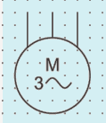
3.2.6.1 Induction Motor, Three-Phase, Squirrel Cage
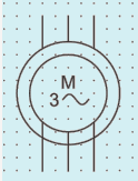
3.2.6.2 Induction Motor with Wound Rotor, three Phase
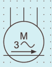
3.2.6.3 Induction Motor, Three-Phase, Star-Connected

3.2.6.4 Linear Induction Motor, Three-Phase
3.2.7 Transformers with two Separate Windings

3.2.8 Auto-Transformer

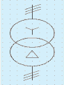
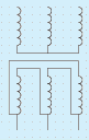
3.2.9 Three-Phase Transformer
3.2.9.1 Three-Phase Transformer, Connection Star-Delta/Form 1
29
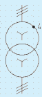
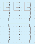
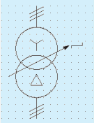
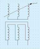
3.2.9.7 Three-Phase Transformer, Connection Star ‒ Zigzag with the Neutral brought out/Form 1
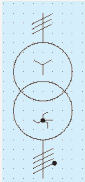
3.2.9.8 Three-Phase Transformer, Connection Star ‒ Zigzag with the Neutral brought out/Form 2
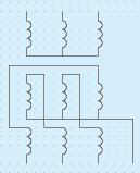
3.2.9.9 Three-Phase Transformer, Connection Star ‒ Star-Delta/Form 1

3.2.9.10 Three-Phase Transformer, Connection Star ‒ Star-Delta/Form 2
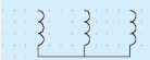

3.2.10 Starter

3.2.11 Direct-on-Line Starter for Reversing Motor

SP 30 : 2023
3.2.12 Star-delta Starter

3.2.13 Auto-transformer Starter

3.2.14 Rheostatic Starter

3.2.15 Switch

3.2.16 Contactor

3.2.17 Relay
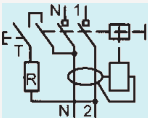
3.2.18 Circuit-breaker

3.2.19 Isolator

3.2.20 Residual Current Circuit Breaker

3.2.21 Overvoltage Protection Device

3.2.22 Fuse

3.2.23 Signal Lamp

3.2.24 Link

3.2.25 Distribution Board, Cubicle Box, Main Fuse Board with Switches

3.2.26 Socket Outlet, 6A

3.2.27 Socket Outlet, 16A

3.2.28 Plug

3.2.29 Voltmeter

3.2.30 Ammeter A
3.2.31 Wattmeter W
3.2.32 Varmeter lar
3.2.33 Power Factor Meter Cos φ
3.2.34 Ohmmeter Ω
3.2.35 Indicating Instrument (General Symbol)
3.2.36 Recording Instrument (General Symbol)
3.2.37 Integrating Meter

3.2.38 Watthour Meter Wh
3.2.39 Clock
3.2.40 Master Clock
3.2.41 Current Transformer

3.2.42 Voltage Transformer

3.2.43 Wiring on the Surface

3.2.44 Wiring in Conduit

3.2.45 Lamp

3.2.46 Lamp Mounted on a Ceiling

3.2.47 Emergency Lamp

3.2.48 Spot Light

3.2.49 Flood Light

3.2.50 Heater

3.2.51 Storage Type Water Heaters

3.2.52 Bell

SP 30 : 2023
3.2.53 Buzzer

3.2.55 Ceiling Fan

3.2.55 Exhaust Fan

3.2.56 Fan Regulator

3.2.57 Aerial

3.2.58 Radio Receiving Set

3.2.59 Television Receiving Set

3.2.60 Manually Operated Fire Alarm

3.2.61 Soft Starter

3.3 Solar PV and EV charging
3.3.1 Grid tie Inverter

3.3.2 Bidirectional Meter

3.3.3 Electric Charging Station
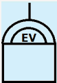
3.3.4 Electric Charging Point

3.2.5 Automatic Fire Detector Switch

4 LETTER, SYMBOLS AND SIGNS
4.0.1 Quantities and units in electrotechnology, in addition to electricity and magnetism, covers other subjects, such as radiation and light, geometry, kinematics, dynamics and thermodynamics. Several disciplines interact with each other such that terminology used in one discipline becomes closely interrelated with that of the other. In order to enable uniform understanding and representation, the letter symbols and signs used in abbreviations for denoting quantities, their functions and units shall conform to those recommended in IS 3722 (Part 1) and IS 3722 (Part 2).
4.0.2 Guidance on the choice of alphabet and their type, representation of vector quantities, symbols of units, numerical values, and guidance on the use of subscripts are covered in IS 3722 (Part 1).
4.0.3 Table 1 of IS 3722 (Part 2) gives a reference list of symbols and subscripts used in electrotechnology.
| Graphical symbols for diagrams in the field of electrotechnology: Part 11 Architectural and topographical installation plan and diagrams |
Various types of diagrams and charts are required to be prepared during the planning and execution stages of an electrical installation work. It is therefore necessary to define the different types of diagrams, charts and tables, their purposes and format and the guiding principles for preparing them for maintaning uniformity.
This section of the Code covers general guidelines on the preparation of diagrams, charts, tables and marking.
The guidelines for marking of conductors is given in 3.6. It provides a common basis for understanding and identifying conductors and apparatus terminals, but more importantly, ensure safety to operating and maintenance personnel.
This section of the code (Part 1/Sec 4) covers guidelines for preparation of diagrams, charts and tables in electrotechnology and for marking of conductors.
The standards listed in Annex A contain provisions, which through reference in this text, constitute provisions of this standard. At the time of publication, the editions indicated were valid. All standards are subject to revision, and parties to agreements based on this standard are encouraged to investigate the possibility of applying the most recent editions of the standards.
A diagram may show the manner in which the various parts of a network, installation, group of apparatus or items of an apparatus are interrelated and or interconnected.
A chart may show the interrelation between:
a) different operations,
b) operations and time,
c) operations and physical quantities, and
d) states of several items.
A table replaces or supplements a diagram or a chart.
The main classifications are:
a) Explanatory diagrams,
b) Explanatory charts or tables,
c) Wiring diagrams or wiring tables, and
d) Location diagrams or tables.
Explanatory diagrams are intended to facilitate the study and understanding of the functioning of an installation or equipment. Three types are defined as under:
SP 30 : 2023
Relatively simple diagram to facilitate the understanding of the principle of operation. It is a diagram in which an installation or equipment together with its functional interrelationships are represented by symbols, block symbols or pictures without necessarily showing all the connections.
Explanatory diagram intended to facilitate the understanding of the functioning in detail. It shows by symbols an installation or part of an installation and the electrical connections and other links concerned with its operation.
c) Equivalent Circuit Diagram
Special type of circuit diagram for the analysis and calculation of circuit characteristics.
Explanatory charts or tables are intended to facilitate the study of diagrams and to give additional information. Examples are given as under:
a) Sequence Chart or Table
Gives the successive operation in a specified order.
b) Time Sequence Chart or Table
Is one which in addition takes account of the time intervals between successive operations.
Wiring diagrams are intended to guide the making and checking of the connection of an installation or equipment. For an equipment, they show the internal or external connections or both. The diagrams may sometimes show the layout of the different parts and accessories, such as terminal blocks and the wiring between them.
Diagram represents all connections within a unit of an installation.
Diagram represens the connections between the different units of an installation.
Diagram showing the terminals and the internal and/or external conductors connected to them.
NOTE — Any of the wiring diagram may be replaced or supplemented by a table.
A location diagram or table contains detailed information about the location of parts of the equipment (for example, terminal blocks, plug-in units, sub-assemblies, modules, etc.). It shows the item designations used in related diagrams and tables.
NOTES
1 A location diagram need not necessarilym be to the scale.
2 Several types of diagrams may be combined into a single diagram, forming a mixed diagram. The same drawing may form both an explanatory and wiring diagram.
3.2.1 The method of representation is distinguished by the:
a) number of conductors, devices or elements represented by a single symbol (see 3.2.1.1);
b) arrangement of the symbols representing the elements or parts of an item of apparatus (for example, detached or assembled) (see 3.2.1.2); and
c) placing of the symbols to correspond with the topographical layout of the devices (see 3.2.1.3).
According to the number of conductors, devices or elements represented by a single symbol, the two methods of representation as given below may be distinguished.
Two or more conductors are represented by a single line.
In particular, a single line may represent:
circuits of a multi-phase system;
circuits which have a similar electrical function;
circuits or conductors which belong to the same signal path;
circuits which follow the same physical route; and
conductor symbols which would follow the same route on the diagram.
Several similar items of apparatus may accordingly, be represented by a single symbol.
Each conductor is represented by an individual line.
According to the arrangement of the symbols representing the elements or parts of an item of apparatus on the diagram, the methods of representation are given below:
The symbols for the different parts of an item of apparatus or of an installation or equipment are drawn in close proximity on the diagram.
The symbols for the different parts of an item of apparatus or of an installation are separated and arranged in such a way that the symbols for mechanical linkages between the parts which work together may be drawn easily.
The symbols for the different parts of an item of apparatus or of an installation are separated and arranged in such a way that the circuits may easily be followed.
The positions of the symbols on the diagram correspond wholly or partly to the topographical (physical) location of items represented.
The following are examples where topographical representation may be used.
a) Wiring diagrams;
b) Architectural diagrams; and
c) Network diagrams.
NOTE — Several of these methods of representation may be used on the same diagram.
3.3.1 Item is a term used for component equipment, plant, unit, etc, which is represented by a graphical symbol on a diagram. The item designation is shown at an appropriate place near the graphical symbol of the item. This designation correlates the item on different diagrams, parts list, circuit descriptions and components in the equipment.
3.3.2 An item designation may be used for general or special purposes depending on the kind of information required. Guidelines on assignment of item designation, groups together with standard letter codes for the same are covered in IS 8270 (Part 2), IEC 81346-1 and IEC 81346-2.
3.4.1 Paper sizes for drawings shall preferably be according to the international A-series (see IS 1064). The choice of drawing sizes should be decided after taking into account the necessary factors enumerated in 2.2 of IS 8270 (Part 2).
3.4.2 In IS 2032 series of standards and IS 12032 series of standards, different kinds of symbols as well as symbols of different forms are specified to the extent possible. Any symbol may be composed using the guidance from IS 2032 and Part 1/Sec 3 of the Code, IEC 60417 and ISO 7000. The basic rules for the choice of symbols shall be:
a) to use the simplest form of symbol adequate for the particular purpose;
SP 30 : 2023
b) to use a preferred form wherever possible; and
c) to use the chosen form consistently throughout the same set of documentation.
3.4.3 Specific guidelines on the application of IS 2032 series of standards, IS 12032 series of standards, IEC 60417 and ISO 7000 with the objective of selection of choice of alternative symbols, symbol sizes, line thickness, orientation of symbols and methods of indicating symbol location are covered in IS 8270 (Part 3).
3.5.1 Interconnection diagrams and tables provide information on the external electrical connections between equipment in an installation. They are used as an aid in the fabrication of wiring and for maintenance purposes. Information on the internal connections of units are normally not provided but references to the appropriate circuit diagram [see IS 8270 (Part 4)] may be provided.
3.5.2 The diagrams may employ single or multiple representation and may be combined with or replaced by tables, provided clarity is maintained. Tables are recommended when the number of interconnections is large.
3.5.3 Guidance on layout, identification and types of interconnection diagrams and tables are given in IS 8270 (Part 5).
3.6.0.1 The purpose of marking is to provide a means whereby conductors can be identified in a circuit and also, after they have been detached from the terminals to which they are connected. Main marking is a system of marking characterizing each conductor or group of conductors irrespective of their electrical function. Supplementary marking is used as supplement to a main marking based on the electrical function of each conductor or group of conductors.
3.6.0.2 The various methods of marking applicable to electrical installations and the equipment which form part of them are covered in IS 5578.
For the purposes of this Code, the provisions of Table 1 of IS 11353 shall apply for the general application of marking conductors in installation. The rules also apply for marking conductors in assembles, equipment and apparatus. Reference is also drawn to the provision contained in relevant Indian Standard.
Bus-bars and main connections which are substantially in one plane shall be arranged in the order given in 3.6.2.1 or 3.6.2.2 according to the system. The relative order remains applicable even if any poles of the system are omitted.
The order of phase connection shall be red, yellow and blue:
a) When the run of the conductors is horizontal, the red shall be on the top or farthest away as viewed from the front.
b) When the run of the conductors is vertical, the red shall be on the left or farthest away as viewed from the front.
c) When the system has a neutral connection in the same place as the phase connections, the neutral shall occupy an outer position.
d) Unless the neutral connection can be readily distinguished from the phase connections, the order shall be red, yellow, blue and black.
The order of arrangement shall be positive, mid-point (if available) and negative:
a) When the run of the conductors is horizontal, the positive shall be on the top or farthest away as viewed from the front.
b) When the run of the conductors is vertical, the positive shall be on the left or farthest away as viewed from the front.
c) When the system is three-wire system with the conductors in the same place, the neutral (mid-wire) shall occupy the middle position.
SP 30 : 2023
The International System of Units (SI) have received worldwide acceptance and is accepted in most of the countries. It had been introduced in India under the Weights and Measures Act, 1976. Use of SI Units in matters relating to electrical engineering practice has many advantages.
This Section of the Code is restricted to electrical units only.
This Section of the Code (Part 1/Sec 5) covers units and systems of measurement in electrotechnology.
The standards contain provisions, which through reference in this text, constitute provisions of this standard. At the time of publication, the edition indicated were valid. All standards are subject to revision, and parties to agreements based on this standard are encouraged to investigate the possibility of applying the most recent editions of the standards.
IS/Other Publications
Title
IS/ISO 80000-2 : 2009
Quantities and units — Mathematical signs and symbols to be used in the natural sciences and technology
SI unit of electric current, equal to the electric current corresponding to the flow of (1/1.602 176 634) × 1019 elementry electric charges per second.
The quantity of electricity conveyed in one second by a current of one ampere.
The capacitance of an electric capacitor having a difference of electric potential of one volt between the plates, when it is charged with a quantity of electricity of one coulomb.
The inductance of a closed circuit in which an emf of one volt is produced when the current in the circuits varies at the uniform rate of one ampere per second.
The electrical resistance between two points of a conductor when a constant potential difference of one volt, applied to these points, produces a current of one ampere in the conductor, provided no emf is generated in the conductor.
The difference of electric potential which exists between two points of a conductor carrying a constant current of one ampere, when the power dissipated between these points is one watt.
The magnetic flux which, linked with a circuit composed of a single turn produces in it an emf of one volt if it is uniformly reduced to zero in one second.
The power which results in the production of energy at the rate of 1 J/s.
3.1.9 Siemens (Unit of Electric Conductance)
The conductance of a conductor of resistance 1 ohm and is numerically equal to 1 ohm-1.
3.1.10 Tesla
The tesla is a magnetic flux density of 1 Wb/m2.
3.2 The electrical units defined in 3.1, together with their expression in terms of other units, recommendations on the selection of their multiples and submultiples and supplementary remarks (if any) are enumerated in Table 1.
Table 1 Electrical Units of Measurement
(Clause 3.2)
| Sl No. | Quantity | Name | Symbol | Expression in Terms of Other Units | Expression in Terms of SI Base Units | Selection of Multiples |
|---|---|---|---|---|---|---|
| (1) | (2) | (3) | (4) | (5) | (6) | (7) |
| i) | Electric current | ampere | A | - | - | kA, mA, µA, nA, pA |
| ii) | Power | watt | W | J/s | m<sup>2</sup>.kgs<sup>-3</sup> | GW, MW, kW, mW, µ W |
| iii) | Quantity of electricity, electric charge | coulomb | C | - | s.A | kC, µC, nC, pC |
| iv) | Electric potential, potential difference, electromotive force | volt | V | W/A | m<sup>2</sup>.kgs<sup>-3</sup>.A<sup>-1</sup> | MV, kV, mV, µ V |
| v) | Capacitance | farad | F | C/V | m<sup>2</sup>.kg.s<sup>-1</sup>.A<sup>-1</sup> | mF, µF, nF, pF |
| vi) | Electrical resistance | ohm | Ω | V/A | m<sup>2</sup>.kg.s<sup>-1</sup>.A<sup>-2</sup> | G Ω, M Ω. K Ω, m Ω,... µ Ω |
| vii) | Conductance | siemens | S | A/V | m<sup>-2</sup>.kg<sup>-1</sup>.s<sup>-1</sup> | kS, mS, µS |
| viii) | Magnetic flux | weber | Wb | V.s | m<sup>2</sup>.kg.s<sup>-2</sup>.A<sup>-1</sup> | mWb |
| ix) | magnetic flux density | tesla | T | Wb/m<sup>2</sup> | kg.s<sup>-1</sup>.A<sup>-1</sup> | mT, µT. nT |
| x) | Inductance | henry | H | Wb/A | m<sup>2</sup>.kg.s<sup>-2</sup>.A<sup>-2</sup> | mH, µH, nH, pH |
| xi) | Conductivity | siemens/metre | S/m | - | m<sup>1</sup>.kg<sup>-1</sup>.S<sup>1</sup>, A<sup>1</sup> | MS/m, kS/m |
| xii) | Electric field strength | volt/metre | V/m | - | m.kg.s<sup>-1</sup>.A<sup>-1</sup> | MV/m, kV/m or V/mm, V/m, mV/m, µV/m |
| xiii) | Permeability | henry/metre | H/m | - | m.kg.s<sup>-2</sup>.A<sup>-2</sup> | µH/m, nH/m |
| xiv) | Permittivity | farad per metre | F/m | - | m<sup>-1</sup>.kg<sup>-1</sup>.s<sup>4</sup>.A<sup>2</sup> | µF/m, nF/m, pF/m |
| xv) | Reluctance | 1 per henry | H<sup>-1</sup> | - | m<sup>-2</sup>.kg<sup>-1</sup>.s<sup>2</sup>.A<sup>2</sup> |
SP 30 : 2023
Standardization of basic parameters, such as voltage, currents and frequency is a pre-requisite to laying a sound foundation for further work relating to product or installation engineering. The values of basic parameters recommended in this section are based on IS 12360.
Reference to CEA (Safety) Regulations, 2010 may also be made.
This section of the Code (Part 1/Sec 6) covers standard values of a.c. and d.c. distribution voltages, preferred values of current ratings and standard system frequency.
IS No
Title
1076 (Part 1) : 1985/
ISO 3 : 1973
Preferred numbers: Part 1 Series of preferred numbers
12360 : 1988 Voltage bands for electrical installations including preferred voltages and frequency
16711 : 2017 48 V ELVDC Distribution System — Guidelines
3.0.1 Standard values of voltages as mentioned in IS 12360 relating to a.c. transmission and distribution systems are reproduced in this section. However, it may be noted that for types of installations covered in subsequent parts of the Code, lower voltage values would be more relevant.
3.0.2 For medium and low voltage of distribution system, nominal voltages were 230 V for single-phase and 230/400 V for three-phase system were the recommended standard values. Later on, to align with IEC recommendations and in view of the economic advantages, nominal values of 240 V for single-phase and 240/415 V for three-phase were adopted with a tolerance of ± 6 percent. IS 12360 may be referred for the latest values.
3.0.3 In the case of voltages above 1 kV, product standards relate the voltage rating of equipment with respect to highest system voltages (generally, 10% above the nominal voltage).
3.1.1 Single-phase, Two-wire System
The standard voltage shall be as per IS 12360.
3.1.2.1 The standard voltages for three-phase system shall be as per IS 12360.
3.1.3 As per the international standards, the direct current (d.c.) of 60V is established as the upper limit for a Safety Extra Low Voltage circuit (SELV), that is, safe to touch directly under dry conditions. Considering both safety and distribution losses, 48V is chosen as the distribution voltage for d.c.
3.1.4 For ELVDC and LVDC, IS 16711 may be referred.
3.2.1 The voltage at any point of the system under normal conditions shall not depart from the declared voltage by more than the values given below:
a) 6 percent in the case of low or medium voltage;
NOTE — IS 12360 may be referred for the latest provisions.
b) 6 percent on the higher side or 9 percent on the lower side in the case of high voltage; or
c) 12.5 percent in the case of extra high voltage.
NOTE — The permissible variations given above are in accordance with CEA (Safety) Regulations, 2010, and are applicable to the supply authorities.
3.2.2 For installation design purposes, the limits of voltage between which the system and the equipment used in the system shall be capable of operating continuously are as follows:
| System Voltage (Un) | Highest Voltage (Um) | Lowest Voltage |
| (1) | (2) | (3) |
| 240 V | 264 V | 216 V |
| 415 V | 457 V | 374 V |
| 3.3 kV | 3.6 kV | 3.0 kV |
| 6.6 kV | 7.2 kV | 6.0 kV |
| 11 kV | 12 kV | 10 kV |
| 22 kV | 24 kV | 20 kV |
| 33 kV | 36 kV | 30 kV |
| 66 kV | 72.5 kV | 60 kV |
| 132 kV | 145 kV | 120 kV |
| 220 kV | 245 kV | 200 kV |
| 400 kV | 420 kV | 380 kV |
| NOTES | ||
| 1 This variation in voltage should not be confused with the permissible variation from the declared voltage as given in 3.2.1. | ||
| 2 IS 12360 may be referred for the latest provisions | ||
5.2 The limits within which the frequency shall be maintained are governed by the CEA (Safety) Regulations, 2010.
SP 30 : 2023
The basic criteria in the design of electrical installation are enumerated in this section which shall be adhered to during the planning stages. The specific nature of each occupancy calls for additional information, which are summarized in the respective sections of the Code.
Considerable assistance has been derived from IS 732. It may be noted that subsequent requirements of the Code would, however, provide adequate guidelines in respect of achieving the desired levels of specific planning, work execution, workmanship and safety.
This Section of the Code (Part 1/Sec 7) enumerates the fundamental principles of design and execution of electrical installations.
The standards listed below contain provisions, which through reference in this text, constitute provisions of this standard. At the time of publication, the editions indicated were valid. All standards are subject to revision, and parties to agreements based on this standard are encouraged to investigate the possibility of applying the most recent editions of the standards:
IS/Other Publications Title
SP 7 : 2016 National Building Code of India
SP 72 : 2010 National Lighting Code
CEA Regulations Central Electricity Authority (measures related to Safety and Electric Supply) Regulations, 2010
Central Electricity Authority (Technical Standards for Construction of Electrical Plants and Electric Lines) Regulations, 2010
Central Electricity Authority (Safety Requirements for Construction, Operation and Maintenance of Electric Plants and Lines) Regulations, 2011
For any electrical installation to be safe, functional, easy to use, augmentable, prone to minimal breakdowns requiring zero or minimum down time and conforming to all Statutory Provisions. Electrical Installation as part of Building Service, design shall be based on fundamental principles as given under this section. Consideration shall also be given to related recommendations under National Building Code.
Under environmental and energy conservation aspects, all related provisions shall be considered under fundamental principles, comprising of natural light, ventilation, thermal insulation, solar systems etc.
It is an initial important step which helps the work to get completed smoothly and in time with minimum changes and reworking and without conflicts with the work of other utility services.
Proper coordination and collaboration between the user, architect, civil and electrical engineer, suppliers of electricity, water, telephone, cable/internet etc. shall be ensured from the planning stage of the installation. Compiling requirements of such various building services providers, and establishing a common platform amongst the team leaders of various agencies working on these services, is an important part under planning.
Depending on type of utility, various electrical aspects involved shall be considered and discussed at planning stage amongst stake holders. For example, air-conditioning system may require limited heat transmittance from walls, roof and fenestration; lifts have requirements such as size of lift shaft, pit, overhead, machine room etc. The requirements shall be complied with (for more details, refer Part 1/Sec 15).
It is necessary to consider following points during preparation of plans with consent of related agencies of building/utility service providers, for smooth and timely completion of work without conflicts between various service providers.
Following points shall be considered during preparation of site plan/layout:
a) In case of any overhead/underground line(s) on the proposed site, it is important to check/obtain mandatory clearances from any proposed structure, as per CEA Regulations and NOCs from the concerned authorities (see Annex A).
NOTE — Refer Reg(58), (60), (61), (63) and (65) of CEA (Measures Related to Safety and Electric Supply) Regulations, 2010.
b) Earthing stations/pits to have an access for testing, maintenance/watering and requirement of minimum clearance from other underground system.
c) Ducts/trenches/chambers, as per routes of UG systems with required depth/clearance from other underground utility service.
d) Type of system earthing and location of earth electrodes (for example, Foundation earth, ring earth, type A vertical/horizontal rods etc)
Requirement of spaces such as length, width and height for system plant, sub-station, generator, panels, control rooms, shafts etc. to accommodate related equipment with mandated clearances shall be considered.
Doors/openings (width and height), of rooms shall be suitable to size of equipment for in/out movement during installation/maintenance.
Electrical safety is prime importance considering hazards related to human life and fire. Part 1/Sec 22 of this code shall be referred for safety in electrical work.
Appropriate design is a foundation of safe, trouble free and convenient to use installation throughout service life. It shall be based on following principles:
a) Compliance with statutory norms;
b) Safety as topmost priority;
c) Functionality;
d) Quality and continuity of supply;
e) User friendly; and
f) Anticipation of future requirements.
Depending on type/use of building and premises assessment of load shall be done considering area in m2 as a base. This decides the requirement of electrical supply LT or HT, and sub-station if needed and its capacity.
Connected load shall be worked out and assessment of contract demand shall be done. This step is necessary for approaching electrical supply provider.
Further electrical load of important services like lifts, water pumps, emergency services like fire pumps, fire lift, critical services requiring supply integrity during fire and evacuation shall be worked out.
4.3.1 Design shall comprise the following source(s) of electrical supply as per requirement:
a) Primary power — Electrical supply Company;
b) Back-up supply — Gen-set/battery based;
c) Solar PV system — Grid connected/non grid connected; and
d) Uninterrupted power supply – electronic/mechanical UPS based.
Compliance with the requirement of Electricity Supply Code published by the State Regulatory Commission shall be checked for availing supply from distribution licensee.
Detailed electrical drawings are important to plan and schedule execution of work in coordination with other agencies like electrical inspectorate, local bodies etc. Electrical drawings shall include:
a) Location of light, fans, 6A power outlets, generally categorized under lighting load;
b) Location of power outlets for electrical systems/load generally 16A and above;
c) Location of switchboards, distribution boxes, electrical panels;
d) Routes of cabling/busways;
e) Single line diagrams showing switchgears, DBs etc. with their capacities, connected load, cable sizes, protections, etc.;
f) Layouts of panel rooms, meter rooms, sub-stations, Gen-sets with allied equipment; required clearances; and
g) Layout of embedded conduits, wires, grounding conductors etc.
NOTES
1 Where prior approval to drawings is necessary, the same shall be taken from concerned authority.
2 Where necessary supporting specifications and calculations sheets shall be attached to justify capacity of switchgear/cable etc.
3 Coordination with other the drawings of other utility services shall be checked and agreed mutually.
Lighting design shall be as per recommended lux levels, CCT, Glare Index, and shall be in accordance with National Lighting Code (SP 72).
In lighting design guidelines/recommendations shall also be taken into consideration in respect of efficacy (Lumen/ watt), lighting power density etc. mentioned under ECBC.
Wiring installation design shall be as per IS 732. Wiring sizes, class, types, method of installation shall be as per the situation, type of load etc.
Reference for protections to be provided shall be taken from following Sections of Part 1 under this code:
Section 10 Protection for safety — Protection against electric shock
Section 11 Protection for safety — Protection against thermal effect and Protection against fire due to arcing.
Section 12 Protection for safety — Protection against over current and fault current
Section 13 Protection for safety — Protection against voltage disturbances, electromagnetic disturbances and voltage surges
All materials, fittings, equipment and their accessories, appliances etc. used in an electrical installation shall conform to Indian Standards wherever they exist. In case an Indian Standard does not exist, the materials and other items shall conform to relevant International Standard.
| - |
| xvi) | Resistivity | Ohm metre | Ω.m | - | m<sup>1</sup>.kg.s<sup>-1</sup>.A<sup>-2</sup> | G Ω m, M Ω m, k Ω m, Ωcm, m Ω m, v Ω m, n Ω m |
Locations of spaces/room shall be suitable to concerned building/utility service provider from the point of view of minimizing system losses, easy access and facility to repair and maintain.
Allocating space and providing civil work (for example, ducts, shafts, openings, space above false ceiling and below the beam soffit) along the routes of building/utility services shall also be considered at planning stage with required sizes.
Specific ventilation requirement of any particular equipment shall be taken care of (for example, battery rooms and equipment like transformers requiring adequate heat dissipation).
External influences (for example, climatic factors such as rains, sunlight, air quality like humidity, corrosive environments, dusty environment etc. affecting safety, service life, continuity and functionality of electrical installation shall also be considered to adopt required preventive measures.
This requirement shall be considered from the point of view of energy conservation such as solar panels of water heating system and PV systems require shadowless and are usually placed on terrace. NOTE — Use of renewable energy is counted under credit points while evaluating Green Building.
Building/utility service provider shall envisage future requirement and make the required provisions.
SP 30 : 2023