13 COMMISSIONING, OPERATION, MAINTENANCE AND BUILDING PERFORMANCE TRACKING
... 82
ANNEX A DESIGN STRATEGIES AS PER CLIMATE ZONES FOR VARIOUS SEASONS
... 85
ANNEX B PRESCRIPTIVE METHOD FOR ENVELOPE OPTIMIZATION
... 87
ANNEX C TRADE-OFF METHOD FOR ENVELOPE OPTIMIZATION
... 88
ANNEX D WHOLE BUILDING ANALYSIS METHOD FOR ENVELOPE OPTIMIZATION
... 90
LIST OF STANDARDS
... 94
This Code (Part 11) covers the parameters required to be considered for planning, design, construction, operation and maintenance of buildings and those relating to land development, from the point of view of sustainability.
From the dawn of civilization, our ancestors were concerned with preservation and sustenance of environment. The ancient Vedas have several references in them on environmental protection, ecological balance, weather cycle, rainfall phenomenon, hydrological cycle and related subjects. Seers, even at those times, recognized that changes caused due to indiscreet human activities could result in imbalances in seasons, rainfall patterns, crops and atmosphere and degrade the quality of water, air, and earth resources. Basham, in ‘The Wonder that was India’, describes how palaces in Mauryan dynasty in second century B.C., were exquisitely built from carved wood of local deodars. In later years the monasteries, temples and dharmashalas were built with locally available stones and these have withstood the ravages of time. Edwin Arnold, in ‘The Light of Asia’, describes Vishramvan, the palace built with local marble and alabaster for prince Siddharth. The epic Mahabharata describes palace built by Vishwakarma. Kashi Vishwanath Temple in Varanasi was built more than a thousand years ago. Many other ancient monuments in various parts of India are classic examples of sustainable buildings.
The Taj Mahal, built more than four hundred years ago, can accommodate hundreds of people with no suffocation, as the stone jalis in the facia induce air movement and enable natural ventilation. The fort in Mandu has elaborate rainwater harvesting techniques. Havelis in northern India were invariably built around a central courtyard, which brought daylight to all nooks and corners, but the heat was kept out. Many forts and havelis have elaborate provision for evaporative cooling, using khas-screens and rainwater stored at higher plateaus. Sustainability and sustainable buildings have been the way of life in India.
It was not just palaces, monasteries and temples that were built on the platform of sustainable practices. The awareness was innate and intuitive, guided by a clear understanding of nature and driven by total alignment with environment, with the resolve not to harm nature but to respect and revere it, and to live in harmony with it. A reflection of this is visible in the locally evolved climate-responsive architecture that blended with social and cultural mores, leaving behind lasting concepts of building forms and human settlements. These buildings provided comfort to the occupants. They were passive in approach with no external intervention, which in modern times have become quite desirable. Diverse climatic conditions in our country resulted in evolution of different fabrics of built form, with the commonality being the focus on harmony with nature. It becomes obvious to see why all the scriptures, literature, life styles and cultural ethos made reference to the Panchabhoothas, which represent five elements of nature, thus blending the architecture and habitats with nature. Thus, sustainability, and sustainable buildings have been the way of life in India.
Less than a hundred years ago, industrial revolution came to India and changed many of these traditional sustainable practices in Indian buildings. The insatiable thirst for progress and comfort at any cost, altered the equation with nature forever. Concrete, steel, glass and later plastics became the dominant construction materials, beyond stone and wood of yesteryears. Power supply, artificial lighting, water supply and disposal, and thermal environmental control within built environment, were desired and obtained.
The new civilizations grew along the river banks, always regarding rivers as sacred. With the industrial revolution, untreated water, effluents from chemical industries and organic waste were discharged into rivers and water bodies, destroying our precious sources of water for domestic use. In addition, the unsustainable development and usage of buildings have led to huge construction and demolition waste, and municipal solid waste during their operation, which today have become a major problem.
Modern buildings in India consume about 25 to 30 percent of total energy, and up to 30 percent of fresh potable water, and generate approximately 40 percent of total waste. India is now entering the phase of rapid urbanization. Various studies indicate that by 2050, the built up area of India may become four times the current mass, which may pose a major challenge in preserving our fragile environment. Although the present energy consumption per
capita in India is a fraction of that of most developed nations, but with its projected growth, unless enough measures are taken, it may lead to acceleration of environment degradation, contributing to increased carbon footprint leading to global warming and climate change, resource scarcity and inequitable development.
Sustainable buildings have demonstrated reduction in energy and water consumption to less than half of the present consumption in conventional buildings and complete elimination of the construction and operational waste through recycling. The Indian way of life is Aparigraha (minimum possession), conservation (minimum consumption) and recycling (minimum waste). These three attributes are the guiding principles for sustainable buildings as well. With these attributes and its rich heritage, India can make a substantial contribution in this field and eventually lead the world on the path of sustainability.
Developed nations' approach to sustainability generally concentrates on energy efficiency through high technology innovations, and use of products, materials and designs with lower embodied energy. Their green ratings are based on intent, which implies expert inputs and simulation which often can be counter intuitive such as the envisaged load and effective use of energy efficient appliance. Indian construction industry will do better through use of products, materials and designs with lower embodied energy and our traditional wisdom and practices, building in harmony with nature through regional common knowledge, consuming as little as necessary, applying low cost technology innovations, using recycled materials, and recognizing performance (not intent) through easily measurable parameters, wherever feasible. If required, the above approach may be supplemented with an appropriate blend of the emerging and sustainable technology innovations. It is particularly emphasized that the hazard of construction and demolition waste should be properly attended to in view of increased construction and redevelopment activities in the country anticipated in future. This would require that such waste is preferably used at site and the balance, if any, may be sent to recycling plant which is closest to the site.
The Sectional Committee, reviewed the contents of the 2005 version of the Code and observed that due consideration had been given to these important dimensions in building planning, design and construction and during operation through provisions of effective utilization of natural light and ventilation; increased use of renewable energy, material selection including recyclability and reusability aspects; use of low gestation plantations and agriculture and industrial wastes; design approach; proper management practices; efficient electrical and other building services and plumbing services; energy conservation; rainwater harvesting, etc. All these have been duly interwoven throughout the Code addressing both the embodied energy and the operational energy involved, as also showing sensitivity towards the concerns such as ozone depletion, global warming, etc. The Committee, however, felt that in keeping with the present needs as well as likely future scenario, it might be appropriate to completely review all such aspects and give them a special and separate identity in the form of Part of the Code covering approach to sustainability relating to buildings and built environment. Aiming towards such objectives, the Sectional Committee first formulated this Part and incorporated in the 2005 version of the Code through Amendment No. 1 to the Code.
This revision has been taken up to further review this Part and update it particularly in view of the modifications being incorporated in other Parts/Sections in this revision of the Code, to bring coherence among the provisions of this Part and other revised Parts/Sections. The significant modifications incorporated in this revision are:
a) Inclusion of definitions of a number of additional terms such as surface coefficient, surface resistance, thermal transmission and total thermal resistance.
b) Greater emphasis on ensuring barrier free design for universal accessibility, as part of approach to sustainability.
c) Review of provisions on materials and technologies for sustainability and their updating, wherever required.
d) Inclusion of guidelines for selection of window types.
e) Modification of the clause on refrigerants for air conditioning to include refrigerants, considering sustainability aspects.
f) Inclusion of provision for preparation of overall water balance chart, as part of water and waste management.
This Part of the Code provides a comprehensive set of requirements, intended to reduce the negative impact of buildings on the natural environment. It can be readily used by the owners, developers/builders, architects, engineers, building services engineers and other building professionals as well as by manufacturers of building materials apart from the Authorities concerning land and building development, government and private construction agencies and academic and research institutions. The intent of this Part of the Code is to highlight sustainability measures including those referred to in different Parts/Sections of the Code as may be required as well as to define
4
comprehensive sustainability standards for the building construction and related built environment.
The approach to sustainability is founded on principles consistent with this Code, to adequately protect public health, safety and welfare and to provide requirements that do not unnecessarily increase construction cost nor restrict the use of new / innovative materials, products or methods of construction. The benefits of incorporating measures listed in this Part are not only environment friendly, but also result in much better health and productivity of occupants, at minimal additional initial cost over the cost of conventional buildings, while substantially reducing the life cycle cost. This minimal additional cost is offset during a few years usage of the buildings, and vast advantage in cost is accrued during the life cycle of the building.
The measures of sustainable buildings described in this Part, set performance thresholds and incorporate features that allow Authority to customize requirements according to local geographical conditions, environmental priorities and agenda. These are not specific to any rating system and are not intended to provide a single metric indication of overall building performance. The flexibility of these provisions allows the practitioners to easily exercise their judgment in holistically and objectively applying the underlying principles of sustainability to a development or building facility, considering its functionality and required comfort level.
The provisions of this Part of the Code are without prejudice to the concerned statutory provisions including those given in various Acts and Rules and Regulations framed thereunder.
The information contained in this Part of the Code has been brought in coherence with the provisions contained in other parts of the Code, as also with the concerned Indian Standards on various areas. In the formulation of this Part, efforts have been made to take into cognizance the various latest applicable practices followed in the country and abroad, relevant to sustainability in buildings. This has been done by taking into consideration the publications of the American Society for Heating, Refrigeration, Air conditioning Engineers; American Society for Testing and Materials; Bureau of Energy Efficiency, India; Indian Green Building Council; Indian Society for Heating, Refrigeration, Air conditioning Engineers; International Organisation for Standardisation; and The Energy and Resources Institute, India.
All standards cross-referred to in the main text of this Part, are subject to the revision. The parties to agreement based on this Part are encouraged to investigate the possibility of applying the most recent editions of the standards.
For the purpose of deciding whether a particular requirement of this Part is complied with, the final value, observed or calculated, expressing the result of a test or analysis, shall be rounded off in accordance with IS 2 : 1960 ‘Rules for rounding off numerical values (revised)’. The number of significant places retained in the rounded off value should be the same as that of the specified value in this Part of the Code.
Book Supply Bureau Under the License from BJS for LARSEN AND TOUBRO CONSTRUCTION - MANAPAKKAM, CHENNAI ON 17-03-2017 09:00:59 (123.63.84.35) valid up NATIONAL BUILDING CODE OF INDIA
1Scope
1.1 This Part 11 covers the parameters required to be considered for planning, design, construction, operation and maintenance of buildings and those relating to land development, from sustainability point of view.
1.2 This Part of the Code is a supplement to all other Parts/Sections of the Code and shall be read along with the same.
1.3 For all buildings and facilities open to and used by the public, including all forms of public housing by the government/civic bodies and private developers, barrier free access and movement within and around buildings, for persons with disabilities and of different age groups, shall be ensured in accordance with Part 3 ‘Development Control Rules and General Building Requirements’ of the Code.
2Terminology
2.0 For the purpose of this Part of the Code, the definitions given below shall apply.
2.1 Adaptive Thermal Comfort — The comfort that relates indoor design temperatures or acceptable temperature ranges to outdoor meteorological and climatological parameters.
NOTE — The adaptive thermal comfort model refers to the concept of specifying indoor comfort temperature set points based on the physiological, behavioural and psychological measures that the occupants take, voluntarily or involuntarily, to adapt themselves to the thermal environment and achieve comfort.
2.2 Authority Having Jurisdiction — The Authority which has been created by a statute and which, for the purpose of the Code/Part, may authorize a committee or an official or an agency to act on its behalf; herein after called the ‘Authority’.
2.3 Biodiversity — The variability among living organisms from all sources including terrestrial, marine and other aquatic ecosystems and the ecological complexes of which they are a part; this includes diversity within species, between species, and of ecosystems.
2.4 Building Environment — The surrounding in which a building operates, including air, water, land, natural resources, flora, fauna, human beings and their inter-relations.
2.5 Building Performance — The ability of a building to fulfil required functions under intended use conditions or behaviour when in use.
2.6 Built Environment — The collection of man-made or induced physical objects located in a particular area or region.
NOTE — When treated as a whole, the built environment typically is taken to include buildings, external works (landscape areas), infrastructure and other construction works within the area under consideration.
2.7 Disaster — It is a catastrophe, mishap, calamity or grave occurrence in any area, arising from natural or man-made causes, or by accident or negligence which results in substantial loss of life, or human suffering or damage to, and destruction of, property or damage to or degradation of environment, and is of such a nature of magnitude as to be beyond the coping capacity of the community of the affected area.
2.8 Ecological Footprint — The impact of a person or community, expressed as the amount of land required to sustain their use of natural resources.
2.9 Ecosystem — The community of biological organisms and their physical environment, functioning together as an interdependent unit within a defined area.
NOTE — For the purpose of this definition, humans, animals, plants, and microorganisms are individually all considered biological organisms.
2.10 Embodied Energy — The sum total of energy that is used to extract, process, package, transport, and install the material in the building.
NOTE — Embodied energy data is often collected using input and output analysis.
2.11 Emissivity(E) — The ratio of rate of heat emitted by a surface as compared to that of an absolutely black surface under similar conditions. It varies with the temperature of the emitting surface.
2.12 Environmental Impact — Any change to the environment, whether adverse or beneficial, wholly or partially, resulting from environmental aspects of a built environment.
2.13 Green Roof System — An assembly that supports an area of planting/landscaping, built up on a waterproofed substrate at any level that is separated from the natural ground by a human made structure.
2.14 Heat Island Effect — A phenomenon in which air and surface temperature of an area are higher than nearby areas due to the replacement of natural land cover with pavement, building, and other infrastructure.
2.15 Horizontal Sun Angle (HSA) — The horizontal angle between the normal of the window and the sun azimuth angle at a given time (see Fig. 1).
FIG. 1 HORIZONTAL AND VERTICAL SOLAR ANGLE FORMULATION
2.16 Indoor Air Quality (IAQ) — The nature of indoor air that affects the health and well-being of building occupants.
2.17 Indoor Environment Quality (IEQ) — The condition or state of the indoor environment.
2.18 Life Cycle Assessment (LCA) — A method of evaluating a product by reviewing the ecological impact over the life of the product.
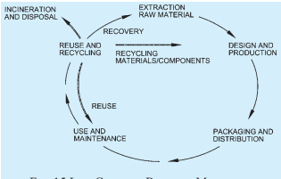
NOTE — At each stage, the product and its components are evaluated based upon the materials and energy consumed, and the pollution and waste produced. Life stages include extraction of raw materials, processing and fabrication, transportation, installation, use and maintenance, and reuse/recycling/disposal.
2.19 Light Shelf — An architectural element that allows daylight penetration in a building. It is usually a horizontal light-reflecting overhang on a window or opening and is placed above eye-level and has a high-reflectance upper surface. This surface reflects daylight onto the ceiling and deeper into a space.
2.20 Non-renewable Resource — A resource that exists in a fixed quantity that cannot be replenished on a human time scale.
NOTE — Non-renewable resources have the potential for renewal only by the geological, physical and chemical processes taking place over hundreds of millions of years. Non-renewable resources exist in various places in the earth's crust. Examples include iron ore, coal, and oil.
2.21 Renewable Resource — A resource that is available naturally, harnessed, and can be replenished.
NOTE — Sustainable use of renewable resource implies that the rate of replenishment, or cleansing takes place at a rate equal to or greater than the current rate of depletion of that resource. Examples include trees in forest, grasses in grassland, and fertile soil.
2.22 Reuse — Using a material, product or component of the waste stream in its original form more than once.
2.23 Recycling — A process to convert discarded
materials that would otherwise become waste, into valuable resources.
2.24 Skylight Roof Ratio (SRR) — The ratio of the total skylight area of the roof, measured to the outside of the frame, to the gross exterior roof.
2.25 Solar Heat Gain Coefficient (SHGC) — The fraction of incident solar radiation admitted through a fenestration, both directly transmitted, and absorbed and subsequently released inward through conduction, convection and radiation (see Fig. 2).
FIG. 2 MECHANISM OF SOLAR HEAT GAIN
2.26 Solar Reflectance Index (SRI) — A measure of material's ability to reject solar radiation, as shown by a small temperature rise.
NOTE — SRI of standard black surface (having reflectance of 0.05 and emittance of 0.9) and a standard white surface (of reflectance 0.8 and emittance 0.9) are taken as 0 and 100, respectively.
2.27 Surface Coefficient (f) — The thermal transmission by convection, conduction and radiation from unit area of the surface, for unit temperature difference between the surface and the surrounding medium. It is expressed in W/m²K.
NOTE — The value of f depends on many factors, such as, air or fluid movement in contact with the surface, roughness and emissivity of the surface and upon the temperature and nature of surroundings.
2.28 Surface Resistance (1/f) — The reciprocal of surface coefficient. It is expressed in m²K/W .
2.29 Sustainability — The state in which components of ecosystem and their functions are maintained for the present and future generations.
NOTES
1 Sustainability is the goal of sustainable development and can result from the application of the concept of sustainable development.
2 In building construction, it relates to how the attributes of the activities, materials/products or services used in construction work, or the use of construction works, contribute to the
8
maintenance of ecosystem components and functions for future generations.
3 While the challenge of sustainability is global, the strategies for sustainability in building construction are local and may differ in context and content from region to region.
4 ‘Components of ecosystem’ includes plants and animals, as well as humans and their physical environment. For humans, this includes a balancing of key elements of human needs namely the economic, environmental, social and cultural conditions for societies’ existence.
2.30 Sustainable Buildings — A building that meets the specified building performance requirements while minimizing disturbance to and improving the functioning of local, regional, and global ecosystem both during and after its construction and specified service life.
NOTE — A sustainable building optimizes efficiencies in resource management and operational performance; and, minimises risks to human health safety and the environment.
2.31 Sustainable Development — The development that meets the need of the present without compromising the ability of future generations to meet their own.
2.32 Thermal Absorptivity — A factor indicating the relative amount of radiation absorbed by a surface as compared to an absorbing black body under the same conditions. Its value is dependent upon the temperature of the source and of the receiving surface.
2.33 Thermal Capacity — The amount of heat necessary to raise the temperature of a given mass by 1° C. Numerically, the thermal capacity per unit area of surface is the sum of the products of the mass per unit area of each individual material in the roof, wall or floor surface multiplied by its individual specific heat.
2.34 Thermal Conductance (R) — The thermal transmission of a single layer structure per unit area divided by the temperature difference between the hot and cold faces. It is expressed in W/m² K.
NOTE — Thermal conductance is a measure of the thermal transmission per unit area through the total thickness of the structure under consideration. Thermal conductivity on the other hand refers to unit thickness of material. Further, this term applies only to a single layer of material and not to a composite insulation or to a structure made up of several layers of materials or medium.
2.35 Thermal Conductivity (k) — The quantity of heat in the steady state conditions flowing in unit time through a unit area of a slab of uniform material thickness of infinite extent and of unit thickness, when unit difference of temperature is established between its faces. Its unit is W/mK.
NOTE — Thermal conductivity is a characteristic property of a material and its value may vary with a number of factors, including density, porosity, moisture content, fibre diameter, pore size, type of gas in the material, mean temperature and outside temperature range. The conductivity value varies from
0.03 W/mK for insulators to 400 W/mK for metals. Materials with lower conductivity are preferred, as they are better insulators and reduce the external heat gains from the envelope or loss of internal heat to outside cold environment.
2.36 Thermal Comfort — That condition of mind which expresses satisfaction with the thermal environment and is assessed by subjective evaluation.
2.37 Thermal Reflectivity — The ratio of the reflected heat to that of the total heat incident on a surface at a certain mean temperature range.
2.38 Thermal Resistance (R) — The reciprocal of thermal conductance. For a structure having plane parallel faces, thermal resistance is equal to thickness (L) of the structure divided by thermal conductivity (k).
R=kL
NOTE — The usefulness of the quantity is that when heat passes in succession through two or more components of the building units, the resistance may be added together to get the total resistance of the structure.
2.39 Thermal Resistivity (1 / k) — The reciprocal of thermal conductivity. It is expressed in mK / W.
2.40 Thermal Transmission or Rate of Heat Flow (q) — The quantity of heat flowing in unit time under the conditions prevailing at that time. Its unit is W.
2.41 Thermal Transmittance (U) — Thermal transmission through unit area of the given building unit divided by the temperature difference between the air or other fluid on either side of the building unit in steady state conditions. It is also called as U-value. Its unit is W/m²K.
NOTE — Thermal transmittance differs from thermal conductance in so far as temperatures are measured on the two surfaces of a material or structure or building unit in the latter case and in the surrounding air or other fluid in the former case. Thermal conductance is a characteristic of the structure or building unit whereas thermal transmittance depends on conductance and surface coefficients of the structure or building unit under the conditions of use.
2.42 Total Thermal Resistance ( RT ) — It is the sum of the surface resistances and the thermal resistance of the building unit itself. It is expressed in m²K/W .
2.43 Tropical Summer Index (TSI) — The temperature of calm air at 50 percent relative humidity which imparts the same thermal sensation as the given environment. TSI (in °C) is expressed as:
T S I = 0. 7 4 5 t g + 0. 3 0 8 t w - 2. 0 6 √(v + 0 . 8 4 1)
where
t g = globe temperature, ° C;
tw = wet bulb temperature, °C; and
v = wind speed, m / s
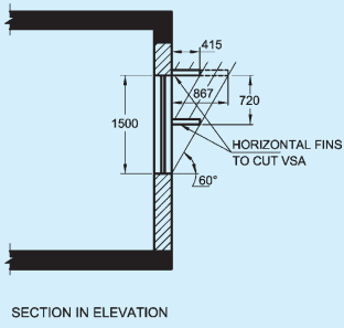
2.44 Vertical Solar Angle (VSA) — The angle that a plane containing the bottom two points of the window and the centre of the sun makes with the ground when measured normal to the shaded surface (see Fig. 1).
2.45 Visual Light Transmittance (VLT) — The ratio of total transmitted light to total incident light.
2.46 Volatile Organic Compound (VOC) — The carbon compounds (excluding carbon monoxide, carbon dioxide, carbonic acid, metallic carbides or carbonates, and ammonium carbonate) which participate in atmospheric photochemical reactions. The compounds vapourize at normal room temperatures.
2.47 Waste — Substances or objects which the holder intends or is required to dispose of.
3Approach to Sustainability
3.1 Need for Sustainable Development
Building construction, occupancy and additions/alterations including preventive and remedial maintenance are always energy and material intensive. Large amount of primary form of natural materials, water, air, energy, etc, are consumed. The energy and material resources required for a building can be categorised as embodied energy, recurring operation energy, refurbishment energy, and end of life disposal. These elements and their use are inter-dependent. There is need for integrated approach of considering them all together in general design development and construction practice. However, conventional approach towards utilizing them is independent of each other and results in very low efficiency in material and resource use.
With increasing urbanization and rapid rise in people's economic level and consumption pattern in many parts of the country, there is an increasing trend to consume more natural resources per capita. This is evident from the aspirational lifestyles and resulting changing tastes and expenditure patterns of individuals and societies. This is equally witnessed from modern construction trends and changing sky lines of cities that bear no resemblance to local climate and resource availability. This is constantly putting tremendous pressure on fragile ecosystem by over-exploitation of natural resources adversely affecting biodiversity of our planet. Realizing this fact, there are efforts for a changing approach towards nature from ‘humanization of nature’ to ‘naturization of human’ and more recently towards sustainable development. The concept is to ensure that every living being on earth have equal opportunity to utilize the natural resources for survival and mutual sustenance.
To achieve this, it is important to accept the major challenge in controlling and judiciously using natural resources to shrink ecological footprint. The way to achieve this is by holistically planning our growth needs, one of which is construction and combining them with need based economy, but at the same time without compromising on functionality and essential comforts.
The basic components of building facility, their inter-relation, tradeoffs and effect on surrounding micro-climatic conditions have to be estimated, to achieve the harmony between buildings and ecological surroundings. Ideally a building should symbiotically fit within prevalent natural cycles. It is necessary to assess the association of various factors involved, rationalizing the impact of construction on neighbourhood and/or building micro-climatic conditions to discern sustainability in the built environment.
3.2Elements of Sustainability
The generalized design process towards sustainability should creatively address the following considerations:
a) Set the design parameters to be implemented to be equal to or higher than benchmarking standards given in this Code.
b) Make the basic performance requirements and set standards, applicable/ selectively adaptable to the climatic zone and geological conditions in which the construction is proposed.
c) Have deep understanding of requirements of performance and human comfort in a building and its surroundings, considering building type and use, quality of building and plumbing services as desired, needs of persons with disabilities and of different age groups, and other parameters.
d) Question the need, identify their optimum levels in long term scenario, and take the design provisions to that level only.
e) Ensure what is sustainable today, remains that way in decades to come, and ensure the required performance levels of systems designed. If required extensive damages done could also be rectified/reversed in course of time.
f) Ensure that sustainability is not only in parts, but also a holistic effort and local action should contribute to sustainability.
g) Make efforts to maximize the use of traditional wisdom in design, wherever applicable, as it represents the knowledge about the long-term behaviour of materials and technology and their strengths as well as weaknesses.
h) While having an open approach, assess new materials and technologies for their long-term impact in the context of the country and its development priorities, before accepting them for use.
j) Take decision making processes to measurable levels wherever feasible, in order to make informed choices. Also by willing to accept limitations of decisions made.
k) Take the savings' benchmark targets closer to the minimum consumption standards; undertake value engineering exercises for deciding among the options.
This process emphasizes the requirement of bottom up approach which invariably considers microclimatic and cultural conditions around.
NOTE — The ‘bottom up approach’ concentrates more on how little is consumed; pursue deep understanding of sustainability; uses low technology innovations, materials and practices; recognizes performance to be more important than intent; and necessitates the use of common knowledge and common sense in design decisions. On the contrast, the ‘top down approach’ concentrates more on how much energy is saved; accepts the understanding of sustainability, may not be developed indigenously, more readily; uses high technology innovations, materials and practices; is driven by green brand and accompanying recognitions based on intent; and necessitates expert inputs and simulations.
The design process itself can play a significant role in creating built environment respecting all principles of sustainable development. This has to take into account various climatic zones (like hot-dry, warm-humid, composite, temperate and cold climates) as well as sun path movements, location (prone to tsunami, hurricane, etc), annual wind directions and geological conditions in the design of building, its orientations, wall and roof materials combinations, space layout, fenestrations and landscape. A solar passive architecture that places minimum energy demand in maintaining thermal comfort should be explored foremost.
The sustainable design process should be based on the principles of universal design as per Part 3 'Development Control Rules and General Building Requirements' of the Code, so as to address accessibility needs of persons with disabilities and persons of different age groups.
Functional requirements of buildings have to also measure up to the required comfort levels demanded for all types of user requirements.
3.3 Life Cycle Sustenance
The process flow from concept, design, construction, commissioning, operation and maintenance, and also decommissioning and disposal at the end of useful life of structure, should be planned and important steps
chalked out for sustainable development. This should also take care of possible reuse/recycle of materials/components/structure or parts thereof. Ideally close the loop (cradle to grave) with regards to resources originally used.
3.4Technology Options
The consequential building envelope to create harmonious development and productive living environment with neighbourhood and building environments poses one of the biggest challenges in selection of building materials, technologies and practices. It may be a combination of natural and manmade materials with least embodied energy and also leading to use of rapidly renewable resources. The trade-off between choice of the materials and technologies and their effect on environment has to be balanced with the aim of a closed-loop system. As a holistic approach, all efforts should be made towards,
a) encouraging and harnessing building materials out of agricultural, industrial and bio-wastes, which have an enormous scope for regeneration.
b) encouraging indigenous environment-friendly and acceptable cost-effective technologies and practices in identifying and pursuing sustainable developments amenable to local, cultural and resource diversity.
c) identifying and encouraging appropriate technologies for more research and development applications.
d) making building construction more indigenous, more adaptable to local climatic zone and executable to achieve the basic provisions for sustainable development to ensure sustained availability of building resources through regeneration and/or reuse/recycle.
e) encouraging use of traditional materials, technologies, vernacular design and construction practices, which have stood the test of time and which may be blended with the modern technology applications.
3.5Energy Efficient Design and Processes
All efforts need to be made towards optimum and efficient use of energy sources for life sustenance. The increasing thrust on using non-fossil fuel energy for all needs have to be given priority consideration. The tapping of renewable sources of energy for lighting, heating, cooling and ventilation needs, deserve special attention. For example, an improved day light factor will reduce the day lighting needs by means of
supplementary lighting with added health benefits such as reduced eye strain (associated with constant elimination conditions). India with over 95 percent of the clear design sky available, the design has to fully utilize the associated benefits. While deciding on the energy choices, life cycle cost analysis including tangible and intangible benefits should be made and not look at the onetime initial capital expenditure alone. The end of life options should also be perceived.
3.6 Reduced Embodied and Operational Energy
All designs, materials and technologies, construction practices should be selected and employed, aimed at reducing the overall embodied and operational energy involved in construction and operation of the built facility. The construction should promote sustainability through adoption of local resources (natural and man-made) and skills.
3.7 Integrated Water Management
Considering an ever increasing demand for water for a growing population, efforts are needed to substantially reduce per capita water consumption in buildings. Integrated and sustainable water management focusing on least anthropogenic water discharge from human activities should be pursued. The use of water conserving fixtures, landscaping, rainwater harvesting, aquifer recharging and waste water recycling need to be given due priority consideration.
3.8 Operation and Maintenance of Services
This should involve use of efficient building and plumbing services components and fixtures tailor-made to meet sustainability objectives and creating sufficient awareness among the users of building facility and its services, during the occupancy stage.
3.9 Monitoring Compliances
The measures adopted during design, construction and occupancy stages should be monitored against norms as per this Code at periodic time interval to ensure sustainability.
3.10 Corporate Governance
The concerned top management should ensure association of all stakeholders including the training and awareness in pursuing and achieving needs for sustainable development at all stages of building lifecycle (from design to end of life). The environmental impact assessment should be carried out and remedial measures based on the findings should be taken during the life cycle of the buildings.
3.11Disaster Preparedness
3.11.1 General
Disaster preparedness as part of approach to sustainability is in addition to the normal considerations of structural safety, health safety, fire safety and public safety taken into account in the building planning, design, construction, use and occupancy, and end of life. The disasters may be natural disasters such as earthquake, floods, cyclone, tsunami, landslides and avalanches; and man-made disasters such as nuclear, chemical, and biological disasters, explosions, act of sabotage and terrorism. Consequence of such disasters could be life threatening and debilitating in the long run.
Also man-made or natural disasters can trigger combined form of progressive disasters. The severity index is another important factor which will be governed by geomorphology, wind flows and cyclonic vulnerability, and climatic zone wherein the construction is proposed. See Part 6 ‘Structural Design’ of the Code for structural design of buildings for various loads, forces and effects using various building material options and structure systems.
3.11.2 Approach
The approach to disaster mitigation and management should be holistic and integrated with emphasis on prevention, mitigation and preparedness rather than being relief centric. The approach should emphasize on preparedness through planning, protection, training and partnership measures with associated stakeholders.
These efforts are aimed to protect and conserve existing development and also to minimise losses to lives, livelihood and property with clear cut focus on protection of environment. The approach shall be towards integrating disaster management as a part of design development, construction practices and management, operation and maintenance and end of life strategies. The required awareness should be achieved through multi stakeholder based planning, awareness, displays, mock drills and adequate training to both aged and young.
The disaster mitigation should also comprise identification of risks during construction, risks during occupancy stages/operations and preparing disaster preparedness plan by decommissioning. The occupancy type, density of occupancy and any specific/strategic aspects should be considered while working out disaster preparedness plan to achieve minimum damages and/or losses to lives, livelihood, properties and environment for the sustainable buildings for least damages or losses.
3.11.3 Disaster Risk Assessment and Mitigation
The formulation of disaster preparedness plan for any location should comprise the following steps:
a) Step 1 — Identify the geomorphology; river, coastal and cyclonic proximity; and climatic zone related disasters risks.
b) Step 2 — Identify population, business related disasters and vulnerabilities.
c) Step 3 — Carry out risk assessment through hazard analysis and vulnerability analysis including possible combining effects of multiple hazards. Also include the effect on micro-climate and environment biodiversity. Coastal zones which are falling in high cyclonic flood zone, tsunami, and seismic zones of high intensity and landslide sensitive areas should receive special attention.
d) Step 4 — Identify the socio-economic, socio-political hazards and vulnerabilities attributed to man-made disasters.
e) Step 5 — Prepare a disaster risk mitigation plan supported with sufficient budgetary provisions.
f) Step 6 — The disaster resistant building construction and infrastructure development features shall form part of the submittal to the Authority for statutory approvals.
g) Step 7 — Establish/nominate a responsible senior person/safety officer as controller for regulating, planning and monitoring disaster preparedness plan for whole project. Carry out all constructions, installations and operations in line with the disaster resistant features for each of the vulnerabilities.
h) Step 8 — Prepare and have mock drills at regular intervals for creating awareness and response preparation amongst stakeholder involved.
j) Step 9 — Prepare operation manual for post-construction operation and up keep of disaster resistant features and equipment.
The basic action plan should focus on capacity building amongst stakeholders involved, communication, coordination, role of information technology, role of every individual working at site and role of emergency response cell of building in conjunction with the mitigation plans of local/state level authorities. The possible after-effects on human and natural habitats and mitigation plan should form integral part of disaster preparedness plan for least damage to human life, built environment and related ecosystems.
5Implementation of This Part
Provisions for building planning, design including material selection and structural design, construction, operation and maintenance have been covered in National Building Code of India: Part 0 to Part 10. These also allow various options to be exercised, for example while various building materials have been listed therein along with their quality requirements for compliance, the choice may rest with the owner/building professionals, say for walling or masonry units, the options could be: use of common burnt clay bricks, perforated clay bricks, hollow clay bricks, fly ash lime bricks, fly ash clay bricks, calcium silicate bricks, solid/hollow concrete blocks, light weight concrete blocks, autoclaved aerated concrete blocks, preformed foam concrete blocks or any other alternative specified. This Part of the Code discusses such options from sustainability point of view for guiding in their appropriate selection. Similar explanation applies to other materials as also other aspects in planning, design, construction, operation and maintenance. However, once a choice of material, design methodology, construction technique/methodology, operation and maintenance related options, etc, is made, the provisions given in this Part of the Code for the same shall be complied with. This Part also prescribes provisions to be necessarily complied with so as to help achieve the objective of sustainability.
This Part should, therefore, be implemented in light of the above while following the approach given in 3. The Authority may require submission and verification of relevant documents while applying for building permit, to demonstrate compliance to the requirements of various provisions under this Part.
6Siting, Form and Design
6.1 General
Before initiating the formal design process, it is critical to evaluate all the passive design options to take advantage of local site and climatic conditions,
acceptable thermal comfort conditions and other occupant requirements. Passive techniques are very cost effective, climate responsive and energy efficient and help a building integrate better with its immediate environment and most importantly do not create any negative impact on the environment unlike active systems that may cause various negative impacts including ozone depletion, global warming and environmental disruptions. The objective, therefore, is to encourage passive design strategies for every building as a means to reducing overall energy demand before pursuing active and mechanical means in an effort to not only save energy but also to minimise the overall negative impact on the environment.
The requirements for the development of buildings and building sites that encourages sustainable building practices including siting, form and architectural approach towards sustainable development, are given in 6.2. The purpose includes providing guidelines that establish objectives for siting and form of residential, mercantile, industrial or other building occupancy developments early in the design stage so as to address sustainability through design. These objectives include, but are not limited to, energy conservation, water conservation and reduced greenhouse gas emissions.
6.2 Site Design and Development
6.2.1 Site Assessment Prior to Design
The responsible design professional shall prepare an assessment of the onsite natural resources and pre-site conditions. The person shall,
a) establish, if there are any protected areas such as floodplains; forest department areas; water bodies such as sea, lakes, rivers, wetlands, tributaries and/or streams; coastal regulation protected areas; defence areas; public parks and recreation areas (unless otherwise used for the purpose of the park); natural contours/terrain requiring protection and agricultural land (unless serving an agriculturally related purpose such as storage, processing, transport, etc) and demonstrate that no critical natural resource is impacted by the project and/or dredging operations;
b) establish the degree to which the existing soil at site and hydrology has been disturbed prior to development and demonstrate various site erosion protection measures taken including measures to preserve natural stormwater drainage system, top soil and existing vegetation, minimise soil disturbance as specified in Part 10 ‘Landscape Development, Signs and Outdoor Display Structures
Section 1 Landscape Planning, Design and Development' of the Code;
c) identify and ensure diversion, avoidance of existing water, power, communication, sewerage lines, saving/replanting of old trees, removal of existing invasive vegetation on site and that no invasive vegetation is planted post completion; and
d) identify and ascertain the natural resources available onsite and surrounding areas and ensure optimum utilization of the same in construction and post occupancy.
A site assessment report for the building/development project shall be prepared.
6.2.2 Building Form, Orientation and Shading
The development shall plan on locating, orienting and shading the building so that,
a) there is adequate provision for external shading of the facades during the peak summer season;
b) there is adequate provision for vertical shading to prevent direct solar radiation and glare due to low altitude sun angles, specifically on the eastern and western facades;
c) the building is oriented optimally based on sun-path and engineering analysis; and
d) there is adequate protection for the building envelope against thermal losses, drafts and degradation by natural elements such as wind, dust, sand, snow, rainwater, hail, etc.
The above strategies shall be implemented based on the climatic conditions of the location. Specifically, the designs should be based on the heating degree days and cooling degree days of the actual location of the building. In the absence of this data, a more generalist approach based on the five climatic zones of the country may be used.
The responsible design professional shall carry out building orientation and shading studies and establish the optimal building orientation for the project and ensure appropriate shading design such that the facades are shaded for more than 50 percent of the summer solstice. A solar path analysis shall be done as an aid in arriving at optimum form and orientation for the building. Appropriate shading design can be arrived at either through simulation approach or by using the prescriptive shading norms as indicated in the SP 41:1987 'Handbook on the Functional Requirements of Buildings (other than industrial buildings)'. A design report showing both the optimum orientation and shading design strategies along with justification for the selection of the same shall be prepared.
6.2.3 Thermal Massing
The responsible design professional shall carry out building thermal massing studies to evaluate the impact on thermal mass on the consequent thermal transmittance and energy performance of the building based on the sun-path analysis and local/equivalent weather data. A report showing both the optimal thermal massing and the choice and justification of the proposed wall material of the building together with the design approach for decision making shall be prepared, together with other documents while applying for the building permit.
6.2.4 Reduced Building Footprint in Multi-Storeyed Building Designs
The requirements for open spaces (within a plot) as specified in 8 of Part 3 ‘Development Control Rules and General Building Requirements’ of the Code shall be complied with. In any case, at least 30 percent of the open spaces shall be maintained as softscapes (permeable surface on ground). For areas where the calculated softscape area requirement is less than 10 percent of the total plot area, a minimum of 10 percent softscape area shall be provided.
6.2.5 Optimum Building Volume
For air conditioned buildings, efforts shall be made in design to reduce building volume by reducing floor to floor and floor to ceiling height without compromising the utility and functional efficiency of the building. For natural ventilated buildings or mixed mode ventilated building, the optimum building volume and floor to floor heights to be ascertained and a report on the design and justification of the same shall be prepared.
6.2.6 Building Form Development Plan
A report shall be prepared on the evolution of the form of the building based on science of architecture, climatology and building physics. The plan shall be in line with the decision making process of the project team and a narrative shall be prepared briefly mentioning the justification behind the selected building form and orientation of the building and shading devices to ensure that the final design meets with the intent of this Part.
6.2.7 Natural Ventilation, Cooling and Wind Effects
A report illustrating the evaluation of the various natural ventilation and cooling studies to maximize natural ventilation or mixed mode ventilation based on adaptive thermal comfort criteria for the project, shall be prepared. In addition, for high rise buildings, wind analysis shall be carried out to evaluate the impact of wind movement and natural air flow changes because of the new building proposed to be erected. Strategies
may include application of cross-ventilation and thermal comfort, factoring prevalent wind patterns, seasonality, stack effect and other principles. A narrative on how these aspects have been factored in the design shall be prepared.
6.2.8 Optimal Daylighting
A day lighting analysis study based on the proposed form of the building for the project shall be carried out and a report thereof prepared. It shall be demonstrated that at least 25 percent of the regularly occupied areas of the building achieve sufficient day lighting with a minimum day lighting factor of 2 percent or as described in SP 41:1987 ‘Handbook on the Functional Requirements of Buildings (Other than Industrial Building)’. For details of day lighting harvesting methods and calculations (see 8.1.3.2).
6.2.9 Defining Building Service Life in Terms of Minimum Component Service Life
A building service life plan shall be prepared along with the design and construction documents. The plan shall clearly indicate the design service life and the minimum design service life shall be not less than 60 years for the structure itself and not less than 10 years for various service components, equipment and systems within the building. All plan shall include dismantling, de-mounting and re-use plan.
6.2.10 Life Cycle Assessment (Optional)
The materials and assemblies may be selected based on their carbon footprint (GHG emission potentials) and/or a life cycle assessment of the embodied energy of the product. For more details on LCA analysis of building materials (see 9.1.4).
7External Development and Landscape
7.1 Landscape Planning and Design
The landscape planning and design shall be in accordance with Part 10 ‘Landscape Development, Signs and Outdoor Display Structures, Section 1 Landscape Planning, Design and Development’ of the Code. In addition, the provisions given in 7.1.1 to 7.1.3 shall be followed.
7.1.1 Landscape Design
Proper landscaping helps in maintaining natural capacity of site for stormwater management, filtration, groundwater recharge and maintenance of soil structure thereby contributing to soil organic matter, and preventing erosion. It helps in moderating microclimate through evaporation, transpiration and the uptake and storage of carbon in trees and other vegetation.
7.1.1.1 Microclimatic conditions
Microclimatic conditions play an important role in landscape design and in working out irrigation requirements, as it accounts for the environmental conditions specific to the landscape, including temperature, wind and humidity. For example, a water body can increase the humidity and a wind funnel can increase the evapotranspiration rate and hence the irrigation requirement. The microclimatic conditions may be taken into account in landscape irrigation calculations by applying a microclimate factor.
The average microclimate factor is 1.0 and this refers to conditions where the landscape evapotranspiration rate is unaffected by buildings, pavements, reflective surfaces and slopes. Higher microclimate factor conditions occur where evaporative potential is increased due to landscapes surrounded by heat absorbing and reflective surfaces or due to exposure to particularly windy conditions. Examples of high microclimate factor areas include parking lots, west sides of buildings, west and south sides of slopes, medians, and areas experiencing wind funnel effects. Areas with low microclimate factor include shaded areas and areas protected from wind. North sides of buildings, courtyards, areas under wide building overhangs and north sides of slopes.
Need for reducing the noise at site shall be assessed. If so required, appropriate measures may be taken for noise abatement, such as quieter pavement or road surfacing, dense foliage, earth berms, barriers or screens, and scheduling maintenance activities when site users are not present. Walls, fences and vegetation may also be used to break, guide, deflect or filter the wind and thereby alter its effects. Noise may be reduced with use broad-leaved trees more than with the conifers and this further improves when foliage extends close to the ground. The best location for a noise barrier is either very close to the source or very close to the receiver while the worst position for attenuation is halfway between them. Provisions of Part 8 ‘Building Services, Section 4 Acoustics, Sound Insulation and Noise Control’ of the Code shall be followed.
7.1.1.3 Building shadow considerations on landscape
Vegetation provides climate moderating benefits as well as benefits to human health. Most vegetation requires sunlight in varying degrees for their growth and maintenance. The buildings by their design, shade certain parts of the external areas for some part of the day or other. External landscapes shall be designed taking the shading pattern of the buildings into consideration. For instance the northern side external areas of the building tend to be shaded for large parts
of the day, while the southern side has access to sunlight for most times of the day, the choice of vegetation should be based on the availability of sunlight along different solar exposures and the requirement of various species of vegetation. Vegetation also has the potential to reduce the energy consumption of a building by providing shading and a cool microclimate. Vegetation and/or vegetated structures shall be kept in strategic locations around buildings to reduce energy consumption and costs associated with indoor climate control.
7.1.2 Hard Landscape Design
7.1.2.1 Pervious paving design
Pervious paving helps in holding rainwater, reducing the rate of storm water flow, infiltrating storm water into the ground for reuse and also helps in filtering the rainwater. Besides helping in storm water management, pervious paving helps in reducing the heat island effect. For sustainable site planning, perviousness in the paved areas of the site may be maximized.
However, the rainwater harvesting potential of pervious paving is subject to local geo-morphological formations and the use of the same should be assessed based on local conditions. For example, in coastal areas, where the water table may be high and the water absorptive capacity is low, pervious paving may not be as effective.
7.1.2.2 Heat island effect and parking design
The heat island effect raises the localized temperature, impacting local climate/microclimate. Plants and animals that are sensitive to large fluctuations in day time and night time temperatures may not thrive in areas affected by heat island. Heat islands also exacerbate air pollution as smog is produced faster at higher temperatures and as rising temperatures lead to increased cooling requirements, requiring energy and causing associated emissions.
Open parking areas consisting of concrete and asphalt absorb heat and contribute substantially to the heat island effect. Shading and/or use of light-coloured/high-albedo materials and/or open grid pavement for the site's non-roof impervious surfaces, including parking lots, walkways, plazas, etc, shall be made to help in reducing the heat island effect.
The solar energy should instead be utilized for generation of renewable energy, thus serving the dual purpose of dampening the heat island effect and reduction in use of fossil fuel for energy generation (see 11.16).
7.1.2.3 Post-occupancy maintenance
A site maintenance plan shall be developed that outlines the long term strategies and identifies short-term actions
to achieve sustainable maintenance goals. The plan should address issues such as plant maintenance, integrated pest management, soil management, fertilizer use, rainwater harvesting, reducing freshwater consumption, site safety, and irrigation allotment and schedule.
7.1.3 Soft Landscape Design
7.1.3.1 Preserving top soil
Healthy soils allow rainwater to penetrate, preventing excess runoff, sedimentation, erosion, and flooding. Soils also help clean and store water, and recharge groundwater. By storing water and slowing the delivery of water to plants, healthy soils play a significant role in vegetation health. In areas of previously disturbed soils, soil function shall be restored to rebuild ability of soils to support healthy plants, biological communities, and water storage and infiltration. In existing soils, depending upon the requirement, the need of soil compaction, organic matter levels, and the balance of soil organisms shall be addressed. It shall be ensured that adequate soil volume is made available for proper plant growth. In order to protect soil horizons and maintain soil structure, existing hydrology, organic matter, and nutrients stored in soils, the disturbance to healthy soil shall be limited. Typically, the first 200 mm soil depth is most conducive for plant growth, and is considered as top soil. Where healthy top soil is being disturbed due to construction activities like excavation, the top soil should be stripped and stacked on one side till further use. Use of excessive chemicals such as fertilizers may result in lasting damage to the soil ecology and shall, therefore, be avoided. See Part 10 'Landscape Development, Signs and Outdoor Display Structures, Section 1 Landscape Planning, Design and Development' of the Code, for further details regarding protection of landscape during construction.
7.1.3.2 Ecological design/conserving biodiversity
A diverse range of species, especially native plants can provide habitat for native fauna, including important pollinator species (for example, insects, birds and bats) that are necessary for plant reproduction, including cultivation of crops. Also, biodiversity in landscapes helps in retaining soil nutrients and is more resistant to attacks by pests. The following considerations shall be used:
a) Protection and use of existing vegetation — Such sites shall be selected that do not include habitat for threatened or endangered species. Site may be designed to minimise disruption to existing habitats. Trees designated as important by concerned local, state or central authorities shall be preserved. Mature trees are significant community resources because
of their cultural, aesthetic, or historic relevance and shall be preserved. Transplantation for mature trees within the site or to another site shall be explored, where vegetation clearing is necessary for construction.
b) Use of vegetation that promotes a regional identity and a sense of place — Native plants which are endemic to the location and appropriate non-native plants adapted to site conditions, climate, and design which support biodiversity, reduced pesticide use and water conservation, shall be used. Only non-invasive plants that are nursery grown, legally harvested or salvaged for reuse from on or off-site shall be used.
7.2Rainwater Harvesting — Surface Runoff
7.2.1 Rainwater Harvesting
Rainwater harvesting refers to collection and storage of rainwater and also other activities aimed at harvesting surface and groundwater, prevention of losses through evaporation and seepage and all other hydrological studies and engineering interventions, aimed at conservation and efficient utilization of the limited water endowment of physiographic unit such as watershed. In general, rainwater harvesting is the activity of direct collection of rainwater. The rainwater collected can be stored for direct use or can be recharged into the groundwater. While enough measures should be taken voluntary, the Authority should encourage and appropriately provide for ensuring rainwater harvesting in outdoor built environment.
The system of collection of rainwater and its conservation for future needs has traditionally been practiced in the country, such as through Baoris, step wells, lakes, tanks, roof top collection systems, etc, to meet the domestic and irrigation demands. This also helps to arrest groundwater decline and augment groundwater table, beneficiate water quality in aquifers, conserve surface water runoff during monsoon, reduce soil erosion and inculcate a culture of water conservation.
Two broad approaches to rainwater harvesting are:
a) Storing rainwater for direct use — Under this approach, for domestic and irrigation purposes, the rainwater is directly collected either in the natural or man-made structures such as Nadi, Tanka, Kund, sand filter bed, pond, rooftop rainwater collection structure, etc.
Roof rainwater collection system augments the water demands by collecting rainwater from the roof and diverting it to specially designed storage or recharge tanks, as per the requirement. On sloping roofs, evaporation losses are small, so collection efficiency may be of the order of 85 percent. Rainwater may be collected from any kind of roof. Tiled or metal roofs are easier to use for the purpose and a smooth surface for the roof will help in water flow and collection.
To reduce contamination of rooftop rainwater, the necessary actions and precautions as given below shall be followed:
Avoid overhanging of trees above the roof to prevent leaves and bird droppings falling on the roof.
Do not allow the first rainfall to enter the tank by diverting it away from tank; although human or animal coliforms are not involved, bird droppings or lizard faeces, and other air borne dirt are also to be washed away from the roof.
Filter the water on entering the tank by suitable filter and also cleaning the filter and tank regularly.
Seal tanks to keep out sunlight (to prevent algae growth), mosquitoes, lizards, birds, etc.
Disinfect tanks once in a year with bleaching powder.
b) Recharging groundwater aquifers — This approach involves use of various kinds of recharge structures, which not only arrest the water but also promote water percolation through soil strata to recharge the depleting aquifers. Structures like percolation tank, anicut, gabion, etc, facilitate the recharge of underground aquifers. However, meteorological and hydrological investigations along with geo-technical investigations shall be carried out before selecting the best suited method for groundwater recharge. Direct injection of rainwater through deep bore wells should be avoided for quality control reasons.
For rainwater harvesting a reference to 4.5.12 of Part 9 'Plumbing Services, Section 2 Drainage and Sanitation' of the Code may be made. For further details, reference may also made to good practice [11(1)].
7.3Water Elements and Irrigation Practices
7.3.1 Design and Post Occupancy Maintenance of Water Features
The site maintenance plan (see 7.1.2.3) shall include appropriate maintenance activities for the water features taking care of the following considerations:
a) Use of chemicals likely to harm aquatic life, such as chlorine and bromine shall be avoided.
b) Maintenance activities to ensure that the water features do not create habitat for mosquitoes, shall be included.
c) Water features shall be designed such that they match or mimic water in the natural
18
environment; and water features that are incompatible with the local ecological context (for example, a lake in a desert) shall be avoided.
d) Volumes of rainwater or water from other non-potable sources available on site for use in water features shall be estimated, and water features shall be so designed that these are integrated with the site so as to utilize this water on site, and not require additional water from potable water sources.
e) Non-potable water from sources such as gray water, reclaimed water or storm-water basins shall be collected and used for non-potable applications.
f) Design and maintain water features as natural ecosystems with water source(s), plants and aquatic organisms appropriate for local conditions.
g) Water quality may be enhanced in created water features with biologically-based water treatment including with the use of certain enzymes, mineral, and oxygen-based additives, especially during initial establishment.
h) Natural swimming pools or other water features intended for human contact may require additional treatment methods such as ozonation or thermal treatment.
7.3.2 Water Conservation and Irrigation Practices
Selecting efficient irrigation systems, planting vegetation appropriate for site conditions and climate, and using captured rainwater or gray-water can reduce water waste and conserve sources of potable water. Typically, half of irrigation water may get wasted as a result of evaporation, wind, improper system design, and over-watering requiring the following considerations which may be followed:
a) Low water demand vegetation (xeriscape) and high-efficiency equipment (for example, drip irrigation) and/or climate based controllers for irrigation systems should be used.
b) If turf grasses are to be used, they should be selected, to be regionally appropriate and to minimise post-establishment requirements for irrigation. The turf area should not exceed 30 percent of the total landscaped area.
c) Reuse gray-water, captured rainwater and/or condensate water for irrigation to decrease potable water use for irrigation as well as to create a net benefit to the local watershed by making the landscape part of the natural water-treatment process.
d) If gray-water or wastewater is to be recycled for landscape irrigation, tests should be conducted to determine suitability for reuse.
e) Irrigation systems should be so designed that trees, shrubs and ground cover are irrigated in separate hydrazones such that watering can be discontinued zone by zone as plants become established.
f) A sub-surface drainage system shall be planned in areas covered with turf to collect excess water for reuse.
7.4External Access Design
7.4.1 Reduced Environmental Impacts from Parking Facilities
Open parking areas, if largely made of concrete and asphalt, absorb heat and contribute substantially to the heat island effect. This shall be mitigated by following the considerations given below:
a) Rendering these areas white or light in colour instead of black, so that they may reflect a lot of sunlight back to space rather than absorbing it.
b) Providing shade and/or using light-coloured/high-albedo materials and/or open grid pavement for the site's non-roof impervious surfaces, including parking lots, walkways, plazas, etc.
c) Limiting the net paved area of the site under parking, roads, paths, or any other use so as not to exceed 25 percent of the site area or net imperviousness of the site not to exceed the imperviousness factor as prescribed in 4.5.11.2.1 of Part 9 ‘Plumbing Services, Section 2 Drainage and Sanitation’ of the Code, whichever is more stringent.
Additionally, the following shall be complied with:
More than 50 percent of the total paved area shall have pervious paving/open grid pavement/grass pavers, or
A minimum 50 percent of the total paved area (including parking) shall have shading by vegetated roof/pergola with planters, or
A minimum 50 percent of the total impervious paving area (including parking) shall be topped with finish having solar reflectance of 0.5 or higher.
The external access, including pedestrian walkways/pathways shall be designed and developed in accordance with Part 3 ‘Development Control Rules and General Building Requirements’ of the Code.
7.4.2 Long term Public and Private Transportation Plan
The long term public and private transportation plan shall take care of the following considerations:
a) Incorporating urban transportation as an important parameter at the urban planning stage rather than being a consequential requirement;
b) Encouraging integrated land use and transport planning in cities so that travel distances are minimised and access to livelihoods, education, and other social needs, especially for the marginal segments of the urban population is improved;
c) Improving access of business to markets and the various factors of production;
d) Bringing about a more equitable allocation of road space with people, rather than vehicles, as its main focus;
e) Encouraging greater use of public transport and non-motorized modes;
f) Enabling the establishment of quality focussed multi-modal public transport systems that are well integrated, providing seamless travel across modes;
g) Establishing enforcement mechanisms to ensure efficiency and enhanced safety for the transport system users;
h) Establishing institutional mechanisms for enhanced coordination in the planning and management of transport systems;
j) Introducing intelligent transport systems for traffic management;
k) Addressing concerns of road safety and trauma response;
m) Reducing pollution levels through appropriate travelling practices, better enforcement, stricter norms, technological improvements, use of electrically operated vehicles etc; and
n) Building capacity (institutional and manpower) to plan for sustainable urban transport and establishing knowledge management system.
7.4.3 Bicycle Lanes and Pedestrian Access — Safety and Comfort
Construction of cycle tracks and pedestrian paths in cities enhances safety and thereby enhances use of non-motorized modes. The safety concern of cyclists and pedestrians should be addressed by encouraging the construction of segregated rights of way for bicycles and pedestrians. Apart from improving safety, the segregation of vehicles moving at different speeds helps
improve traffic flow, increase the average speed of traffic and reduce emissions resulting from sub-optimal speeds. Such segregated paths are useful not only along arterials, to enable full trips using non motorist transport but also as a means of improving access to major public transport stations. Such access paths, coupled with safe bicycle parking places, may be provided for promoting an increased use of public transport. Creative facilities like shade giving landscaping, provision of drinking water and resting stations along bicycle corridors should also be encouraged to help mitigate, the effect due to adverse weather conditions. The use of the central verge along many roads, along with innovatively designed road crossings, may be considered for developing as cycle tracks. At busy intersections and high traffic corridors, pedestrian crossing shall be constructed.
Following are some of the features which should be considered while designing pedestrian and cycle/cycle-rickshaw friendly environment:
a) Design and construction ensuring safety and comfort of all the users.
b) Use of following climatic design features for streets and public spaces to make them comfortable for pedestrians, cyclists and public transport users, based on local climate:
Planting of deciduous trees all along the pedestrian/cycling path to provide adequate shade in summer and allow solar access in winter.
Considerations to overhangs, arcades and closely built buildings providing shading and comfort in summer to the public realm.
Orientation of streets to allow the desirable directional wind flow through streets and public spaces in summer and block undesirable winds in winter, to ensure comfort in the public use areas.
c) Signalization of junctions and mid-block crossings on roads to allow safe crossings at grade.
d) Multimodal interchange and provision of good para-transport options and walkability at the neighbourhood level as the most important factor in reducing use of private modes and also reducing transportation demand; and the following to be provided so that people can walk or cycle easily for short trips as well as for accessing mass transport stations:
Fast and convenient interchange between modes (distances between modal changes to be as per multimodal integration and connectivity requirements).
Closest convenient interchange access at
7.4.4 Off Street Parking
The off street parking shall be planned taking care of the following objectives as per Part 3 ‘Development Control Rules and General Building Requirements’ of the Code:
a) To relieve congestion on streets by providing convenient off-street parking and loading facilities in proportion to the demand created by the use;
b) To provide for the safe and orderly movement of traffic through proper design and location of adequate parking, loading, and manoeuvring areas;
c) To protect neighbourhoods and surrounding land uses from vehicular parking, loading and traffic congestion, noise and dust, through proper aesthetic design and location of entries, parking areas, and landscaping;
d) To promote businesses, industries and commercial activities by providing safe, convenient, attractive parking facilities and environments; and
e) To encourage the use of efficient forms of transportation.
7.4.5 Discouraging Subsidized Parking in Public Realm
Subsidized parking in public roads and spaces, especially in urban areas with high traffic density or having likely projected high traffic density should be discouraged to reduce private vehicle usage and inducing a modal shift towards public transport. Parking management may be used as a demand management tool rather than a supply based tool, with the following considerations:
a) Discouragement to the use of car as a feeder or a general mode of transport, with park and ride facilities being only at stations of mass rapid transport system (MRTS).
b) Providing parking only for servicing rather
than for access, and only emergency vehicle access to be provided which can be done through provision of mountable kerbs, etc, on pedestrian dominated streets.
c) No free or subsidized parking in public space and actual parking cost to be defined by market forces.
d) Enforcement of parking caps in areas with mass rapid transport access.
e) Park once-and-walk facilities in busy markets and residential/mixed use areas.
f) Strict enforcement of parking through self-regulating design.
7.4.6 Providing Neighbourhood Connectivity, Walkability and Safety
At the site design and block design level, several measures should be taken for reducing transportation demand and promoting walkability, and ensuring that the neighbourhood is a safe walkable place. These measures should include the following:
a) Vertical mixing of housing and community based uses to ensure vibrancy and safety.
b) Based on local climate, minimum 2 h daylight access to neighbouring buildings to be ensured through provision of required street width-to-height ratios, in accordance with Part 3 ‘Development Control Rules and General Building Requirements’ of the Code.
c) Block sizes and paseos — For blocks where any one side is greater than 200 m in length, a public access cut-through for pedestrians and non-motorized transport (NMT) shall be provided. This ensures connectivity and walkability in the neighbourhood enabling short local trips to be made on foot.
d) The setbacks and boundary wall for commercial properties should be designed so as to also promote safety and encourage pedestrian communication.
7.4.7 Ecology of Streets
As streets constitute about 20 to 25 percent of the impervious cover of the city, they have a large detrimental effect on the heat island effect and ecological character of a city. The following design components should be integrated in street design:
a) Planting of trees as an essential component for all streets to provide shade to pedestrians and reduce solar gain.
b) Use of high albedo (diffused reflectivity) materials for paving and increasing greenery around to reduce heat island effect.
c) Decreasing impervious surfaces through permeable paving, tree planting zones, etc, to increase groundwater infiltration and prevent seasonal flooding.
d) Integrate natural storm water filtration and absorption into street design through bio-filtration beds, bio-swales and detention ponds.
7.5External Lighting Design
7.5.1 Landscape Lighting Design — Allowable Lighting Power Density (LPD)
Light pollution can disrupt circadian rhythms and melatonin production, which has been linked to serious health concerns. Reasonable use of outdoor lighting restores dark night skies and preserves the ambiance of the night. Whether outdoor light is directly adjacent to a species habitat or located at some distance is an important consideration, as through sky glow, the combined effects of artificial lighting on vast numbers of nocturnal species have the potential to disrupt the functioning of entire ecosystems by disturbing balances in competition and predation. The landscape lighting should be designed such that light fixtures emit minimum light as per the specified total fixed lumens and only light the areas as required for safety and comfort. In addition, the lighting shall be efficient complying with the requirements of maximum LPD given in Table 1.
7.5.2 External Signage Design
External signage may be designed to address the following main issues related to overall sustainability:
a) The signage shall be classified as external lit and internal lit and further classified based on functional requirements such as emergency, way finding, etc. The requirements of each type of signage are different and should be evaluated based on the same. The recommended lighting power density is 130 W/m² , maximum for internally illuminated signage, and 25 W/m² , maximum for externally illuminated signage.
b) Illuminated signage forms a substantial part of upward directed lighting. Efforts should be made to shield the lighting.
c) Paints, adhesives, etc, used in the signage should be of low VOC.
d) Fabrication of the signage should be using materials locally available and having a recycled content.
7.5.3 External Lighting
The facades may be lit with fixtures that are shielded,
22
Table 1Maximum Lighting Power Densities for Building Exteriors (Clauses 7.5.1 and 7.5.3)
Sl No.
Area to be Lit
LPDsMax(3)
(1)
(2)
i)
Uncovered parking areas:a) Parking lots and drives
1.6 W/m²
ii)
Building grounds:a) Walkways less than 3 m wideb) 1) Walkways 3 m wide or greater2) Plaza areas3) Special feature areasc) Stairways
3.28 W/linear metre 2.15 W/m² 10.76 W/m²
iii)
Building entrances and exits:a) Main entriesb) Other doors
98.52 W/linear metre of door width 65.68 W/linear metre of door width
iv)
Canopies and overhangs:a) Canopies (free standing and attached and overhangs)
13.45 W/m²
v)
Outdoor sales:a) Open areas (including vehicle sales lots)b) Street frontage for vehicle sales lots in addition to open areas allowance
5.38 W/m² 65.68 W/linear metre
vi)
Building facades
2.15 W/m² for each illuminated wall or surfaceor 16.42 W/linear metre for each illuminated wall or surface length
vii)
Automated teller machines (ATMs) and night depositories
270 W per location plus 90 W per additional ATM per location
viii)
Entrances and gatehouse inspection stations at guarded facilities
13.45 W/m² of uncovered areas covered areas are included under the canopies and overhangs
ix)
Loading areas for law enforcement, fire, ambulance and other emergency service vehicles
5.38 W/m² of uncovered areas covered areas are included in the canopies and overhangs
x)
Drive-up windows at fast food restaurants
400 W per drive-through
xi)
Parking near 24 h retail entrance
800 W per main entry
xii)
Landscaped areas, including individual house courtyards, terraces
2.15 W/m²
with less than 10 percent lumens above 90° from the nadir (see Fig. 3) and the lighting power density of the facade lighting may be as given in Table 1.
7.5.4 Light Trespass Allowance
The light trespass allowance may vary for different site surroundings, and a light should also vary for different settings depending upon the requirements. The site settings may be kept as,
a) Dark — For rural setting.
b) Low lighting setting — For residential areas/sub-urban areas and townships.
c) Medium lighting setting — For medium rise buildings, high rise buildings, commercial/office areas and high density for non-commercial area.
d) High lighting setting — For malls, entertainment areas and city centre areas.
8.3Renewable Energy Integration in Envelope
8.3.1 Integration of Solar Thermal Technologies
Solar collectors that harness the solar energy directly into usable heat can be aesthetically integrated with the building envelope or they may be mounted on the roof of building.
8.3.2 Integration of Photovoltaic Technologies
Building integrated photovoltaic (BIPV) system is the integration of photovoltaic (PV) and the building envelope. The PV modules can be designed and installed to serve the double purpose of both power generation and that of the building skin replacing conventional building envelope materials. By avoiding the cost of conventional materials, the incremental cost of photovoltaic is reduced and its life cycle cost is lower.
A complete BIPV system includes the following:
a) PV modules (which may be thin-film poly or mono crystalline, amorphous with transparent, semi-transparent, or opaque backing);
b) Charge controller, to regulate the power into and out of the battery storage bank (in standalone systems);
c) Power storage system, generally comprising utility grid in utility-interactive systems or, a number of batteries in stand-alone systems;
d) Power conversion equipment including an inverter to convert the d.c. output of PV modules to a.c. compatible with the utility grid;
e) Backup power supplies such as diesel generators (optional), typically employed in stand-alone systems; and
f) Appropriate support and mounting hardware, wiring, and safety disconnects.
While photovoltaic panels as in (a) are considered as PV array, other components given in (b) to (f) are usually referred to as the balance of system (BoS). Not only solar photovoltaic technologies but other ways of producing renewable energy may also be integrated in to design, depending upon suitability to geomorphological conditions, geo-thermal pumps, wind, etc.
8Envelope Optimization
8.1 Building Envelope
The building envelope acts as the interface between indoor and external climatic conditions. It potentially
regulates the building climatic response. The building envelope should be designed to conserve energy substantially. Well designed building envelope maximizes daylight, natural ventilation (access to fresh air) and views to the exterior, and enables to modulate solar heat gain and control/reduce noise. The building envelope may also be designed to integrate systems for renewable energy and rainwater harvesting. In general, the design strategies drawn from long experience in the country in its various climatic zones may be taken into account (see Annex A for guidance).
Building envelope components and their configuration largely determine the amount of heat gain or loss and wind that enters inside the building and extent of natural ventilation in the building. The primary components of building envelope which affect the performance of a building are,
a) walls,
b) roof (including skylights and clerestories),
c) fenestration (openings with or without glazing),
d) floor, and
e) surface finishes.
FIG. 3 FACADE LIGHTING USING SHIELDED FIXTURES
8.1.1 Walls
Walls are a major part of the building envelope, which are exposed to external environment conditions such as solar radiation, outside air temperature, wind and precipitation. The construction of wall and thereby its heat storing capacity and heat conduction property has a major impact on indoor thermal comfort in naturally ventilated buildings and on cooling loads in air conditioned buildings. The wall material, thickness, finishes should be selected according to climate zone and building's comfort requirement. Wall properties that determine heat transfer are thermal conductivity, thermal resistivity, thermal absorptivity, emissivity, thermal reflectivity and thermal capacity (see 2).
8.1.1.1 Enhancement of thermal performance of walls
Thermal performance of walls can be improved by following ways:
a) Thermal insulation (applying insulation on wall surface) — Thermal insulation plays an important role in reducing the thermal conductance or U-value of walls. The effect of insulation is to reduce heat gain and heat loss. Insulation should always be placed on the hotter side of the surface. In hot climate zone, insulation should be placed on the external side of wall composition. Insulation also controls the interior mean radiant temperature (MRT) by isolating the interior surfaces from the impacts of exterior
conditions. Insulation along with infiltration control is important for reducing heating and cooling loads in simple occupancy (skin) load dominated buildings such as residences. In buildings, that are internal load dominated such as offices with high equipment load, the insulation thickness and properties should be determined based on thermal performance analysis including the role of insulation in reducing cooling energy consumption, particularly in hot and dry, composite and warm humid climates. Thermal insulation may be made from a variety of materials and in several forms. Broadly they may be divided into following five categories:
Rigid or semi rigid blocks and boards (such as, mineral wool, expanded polystyrene boards);
Boards with impact or weather resistant surfaces suitable as exterior grade material;
Loose fill (such as, cellulose, fibre glass);
Foam and dry spray (such as, polyurethane or polyisocyanurate); and
Blankets, felts or sheets (such as, fibre glass, mineral wool, closed cell flexible elastomeric foam).
When specifying insulation, its key properties such as thickness, density, thermal resistivity/thermal conductivity value at specified
NATIONAL BUILDING CODE OF INDIA 2016
temperature, long term thermal retention, fire resistance, moisture resistance (structure open/closed cell), water vapour diffusion resistance, etc, should be specified. Insulation should be applied as per manufacturers' recommendations and in a manner so that it achieves rated insulation in terms of thermal resistance or R-value. Damaging or compressing the insulation reduces the effective R-value and compromises thermal performance of the construction assembly.
b) Thermal mass (increasing wall thickness) — Thermal mass in walls enables time delay in impact of external environment on internal conditions. Thermally massive walls have high thermal capacity, and thermal storage capacity increases with increasing compactness, density and specific heat capacity of the materials. Walls (and other building elements such as roof and floor) can be used for thermal storage. The effectiveness of storing heat or coolness can be increased by creating a flow of fluid through the storage media.
Thermal mass is particularly effective in hot-dry climate with larger diurnal range. The building mass stores heat during daytime when outside temperature is high, and releases it to the inside space during night when outdoor temperature is cooler. Thermal mass is also used in storing heat during daytime in cold climates, to release it into the space during night, to warm it up when outdoor conditions are colder. Materials such as concrete, brick and water have high thermal storage capacity and can be used for such application. Storage mass exposed to direct sunlight should be dark in colour to allow larger absorption. It is generally more efficient to have thicker rather than thinner storage mass. The optimum thickness varies between 100 mm and 200 mm.
NOTE — There are ongoing developments based on research, regarding use of improvised materials with special properties such as phase changing characteristics which may be considered in future along with their implications from sustainability point of view.
c) Air cavities (Providing air cavities in walls) — Air cavities in wall reduces heat gain factor. Performance is improved if the cavity is ventilated. Heat is transmitted through air cavity by convection and radiation. Cavity represents resistance that is not proportional to the thickness of the cavity. For thicknesses greater than 20 mm, the resistance to heat flow is nearly constant. Air cavity, however, may not be treated as replacement for higher
insulation, where needed as per the design requirements.
d) Surface finishes (Applying light coloured paints on walls) — Surface colour and finish plays an important role in heat gain and loss from a structure. If external surface of a building is painted with light colour, it will reflect solar radiation. But if the emissivity of the surface colour in the long wave region is also high, the heat flux into the building is considerably reduced. For example, whitewash has a lower reflectivity than aluminium, but will stay cooler when exposed to high solar radiation, due to its high emissivity at low temperatures. The effect of colour on external surfaces is more evident in lighter structure, which offers low resistance to heat flow, and because of low thermal capacity. Ongoing research has made possible paints that are dark but reflect most off infrared (IR) radiation, thereby preventing excessive heat gain.
8.1.2 Roofs
The roofs of buildings receive most of heat throughout the day. Predominantly used construction practices in the country especially in urban areas, mainly involve reinforced cement concrete (RCC) as the roofing element, which has high thermal conductivity. If the roof is exposed to solar heat, the temperature inside will also rise as the day progresses. When buildings are air conditioned, the purpose of the system is to maintain inside the building, a lower temperature than the ambient. If the roof slab is exposed to solar heat, it will allow continuous heat inside the building which in turn will add to the air conditioning load. If the roof is protected from heat incidence by suitably insulating the roof from the heat, the conditions inside can be controlled to a large extent so that the living environment inside the building remains below the ambient temperature throughout the day. The function of roof insulation is to insulate the building against heat inflow from outside during the day. The options for roof insulation are given in 8.1.2.1 to 8.1.2.2. The overall thermal transmittance from the exposed roof should be kept as minimum as possible and under normal conditions, the desirable value should not exceed 0.58W / (m²°C). The ceiling surface of floors which are not to be air conditioned may be suitably insulated to give an overall thermal transmittance not exceeding 1.16W / (m²°C). Some traditionally adopted methods of roof construction like stone Patti and jack-arched roof may be used after evaluating their thermal performance. Mechanism to shade the roof with vegetation will help a great deal in lowering solar exposures.
8.1.2.1 Over-deck and under-deck insulation
In this system a thermal barrier or insulation is provided over RCC roof, so that the amount of heat of the sun reaching the RCC slab of the roof is substantially reduced to prevent the slab from getting excessively heated up. In contrast, if the thermal barrier is provided under RCC roof, as in under-deck insulation, some heat passes through it and heats up the ambience of the room. This decreases the comfort level of the room and if the building is air conditioned, increases the air conditioning load. Over-deck insulation is, therefore, considered advantageous over under-deck insulation in hot climates. Over-deck insulation also protects waterproofing system from damage due to thermal stress caused by continuous variation in diurnal and seasonal temperatures. It also acts as a protection against mechanical damage to water proofing systems. Over-deck insulation material should have adequate compression resistance, low water absorption, resistance to high ambient temperature and low thermal conductivity. Over-deck insulation applications may be carried out by either of the following methodologies:
a) Use of preformed insulation materials — Preformed insulation materials used are classified as given below which may be laid, over the roof surface as per the manufacturers' recommendations:
Expanded polystyrene sheet.
8.1.3 Fenestration
8.1.3.1 Of all the elements of building envelope, windows and glazed areas are most vulnerable to heat gains. Windows are required to bring inside natural daylight and wind, however, with light it also bring in heat. Proper location, sizing and detailing of windows
and shading form is therefore a very important aspect in a solar passive building design. Primary factors/components of a window which have significant impact on energy and cost of the building are window size and placement, glazing, frame, shading (external and internal), and screens or Jalis.
8.1.3.1.1 Window size and placement
The following may be taken into consideration:
a) Height of window head — The higher the window head or lintel, the deeper the penetration of daylight.
b) Sill height (height from floor to the bottom of the window) — The optimum sill for good illumination as well for good ventilation should be between the workspace and head level of a person. For carrying out any task, the suitable work plane levels shall be in accordance with 4.1.3.3 of Part 8 ‘Building Service, Section 1 Lighting and Natural Ventilation’ of the Code. Strip windows provide more uniform daylight. Punched windows should be paired with work areas to avoid creating contrasts of light and dark areas. Windows close to task areas should be with optimum visual transmission without glare with good insulation performance as they may be source of thermal discomfort. Small horizontal openings close to the floors and the ceiling are extremely effective in reducing the window area to reduce heat ingress and provide adequate daylight levels in the space. In case of larger windows, glazing selection and shading effectiveness are quite important to control glare and heat gain.
Use of separate apertures for view and daylight — For good day lighting and glare control, window should have clear glass with a partition for maximum daylight penetration and tinted glass below the clear glass for glare control. The structure in between the two provides a visual break and an opportunity to attach light shelf or shading device.
d) Window wall ratio (WWR) — Window to wall ratio is the net glazing area (window area minus mullions and frame or approximately 80 percent of opening) divided by gross exterior wall area. Gross wall area is the overall area of a wall including openings such as windows and doors, with measurement taken horizontally from outside surface to outside surface and measured vertically from top of the floor to the top of the roof (see Fig. 4).
NOTE — The above represents only one approach in the entire range of window to wall ratio. The issue is primarily of window to wall ratio, and not window to glazing ratio.
9Materials
9.1 General
Building materials choices are important in sustainable design because of the extensive network of activities such as extraction, processing and transportation steps required for making a material, and activities involved thereafter till building construction and even thereafter. These activities may pollute the air, soil and water, as well as destroy natural habitats and deplete natural resources.
One of the most effective strategies for minimizing the environmental impacts of material usage is to reuse existing buildings. Rehabilitation of existing building, their shell and non-shell components, not only reduces the volume of solid waste generated and its subsequent diversion to landfills but also the environmental impacts associated with the production, delivery and use or installation of new building materials.
The use of rapidly renewable materials, recycled materials minimises the adverse impact of natural resource consumption in the manufacture of new building materials. The use of local materials supports the local economy and reduces the negative impact of transportation.
9.1.1 Environmental Concerns and Human Health and Safety Aspects Related to Building Materials
Increased demand for building materials creates a major and diversified impact on the environment. Excessive extraction of raw material diminishes non-renewable natural resources very rapidly. Even during some extraction process, waste is generated whose disposal may pose problems. Sometimes extraction processes may also affect the wildlife. Transportation of building materials from one place to another is also a major indirect factor leading to harmful effects. During manufacturing or processing of some materials like plastic, harmful gases are generated, which are dangerous for human health and environment. There are many frequently used building materials like reconstituted wood products, paints, glues, carpet and upholstery, which may release gases, fumes, etc, from the chemical components used, even long after the installation. These volatile organic compounds (VOCs) affect the environment and human health and may cause headaches, dizziness, respiratory problems and even major diseases in human and other living beings.
9.1.2 Minimizing Green House Gas (GHG) Emission
Construction sector in the country is a major consumer of energy resulting in the largest share of CO₂ emissions in the atmosphere. Cement, steel and bricks, the largest and bulk consumption items in the construction industry, are contributors of large CO₂ emissions. It is estimated that close to a tonne of CO₂ is emitted during the production of every tonne of cement, resulting in very high GHG emission. Similarly, bricks and concrete, which are very widely used construction material have very high GHG emission. Minimizing the consumption of such conventional materials which may contribute to substantial GHG emission, by using alternative materials and alternative methods and techniques can considerably reduce energy and CO₂ emissions.
9.1.3 Building Material
An ideal sustainable building material is not only environment friendly, causes no adverse impact on health of occupants, is readily available, can be reclaimed, can be recycled and is made from renewable raw material, but also uses predominantly renewable energy in its extraction, production, transportation, fixing and ultimate disposal. Practically, this kind of ideal material may not be available, hence when selecting sustainable materials, it may be best to choose materials which fulfill most of these criteria.
9.1.4 Life Cycle Assessment (LCA) of Building Materials
LCA of building materials intends to assess the potential environmental impacts at every stage in the life cycle
of a material (see Fig. 15) right from the raw material sourcing, processing, manufacturing and finishing, up to the product installation, maintenance and ultimately reuse/recycle/demolition. It is a tool to determine the environmental suitability of any building material for a thorough understanding of the environmental impact and the improvement which can be employed at every stage of a material, so as to make a decision for its selection after evaluation of criteria such as embodied energy, performance and durability.
A description of life cycle analysis with respect to various relevant criteria is given below:
a) Embodied energy — It is an important factor to be considered in the life cycle assessment of a material. Minimizing embodied energy means minimizing the impact on the environment. In any building construction use of materials with low embodied energy should be considered.
Table 7 gives classification of building materials based on their energy intensity and gives the comparative embodied energy for a few building materials.
b) Resource reuse and upgradation — It includes saving a material from disposal and utilizing it by renovating, repairing, restoring, or generally improving the appearance, performance, quality, functionality, or value of a product. Efforts should be made to reuse existing, previously occupied buildings – including the structure, envelope and elements, after removing or replacing the elements which have risk of failure/contamination during construction or occupancy. Upgradation of systems should be done in the areas of energy and water efficiency where the previously installed systems are not environment friendly or efficient.
c) Recycled content — To reduce the demand for virgin materials, effort should be made to use the products with identifiable recycled
FIG. 15 LIFE CYCLE OF BUILDING MATERIALS
Table 7Classification of Materials Based on Energy Intensity [Clause 9.1.4 (a)]
Sl No.
Category of Material
Energy Intensity (Range) GJ/t
Examples
(1)
(2)
(3)
(4)
i)
Very high energy
>50
Aluminium, stainless steel, plastic, copper, zinc
9.2Materials and Recommended Sustainable Alternatives
For quality requirements of building materials reference shall be made to National Building Code of India: Part 5 ‘Building Materials’ of the Code. General guidelines and considerations for use of different structural and surface finishing materials and with alternatives for helping in sustainable construction, are given under 9.2.1 and 9.2.2.
9.2.1 Structural Materials
9.2.1.1 Cement concrete
Concrete is a strong, durable material and provides good thermal mass to buildings. However, manufacture of cement used in it is a high energy-intensive process and source of pollution, requiring also high energy for its transportation due to centralized production. Extraction and mining of aggregates also result in natural habitat destruction or deforestations. Following are the recommended alternatives to conventional concrete:
a) Use of pozzolanas and other mineral admixtures for cement replacement in cement concrete and other cement matrix products:
Use of fly ash and slag in cement concrete — Pozzolanas like fly ash or ground slag may be used to replace certain percentage of ordinary Portland cement in cement concrete in accordance with the good practice [11(3)] or cement manufactured by using mineral admixtures like fly ash or ground slag may
be used, in accordance with the good practice [11(3)].
Rice husk ash (RHA) — Rice husk ash, a waste from rice industry, is pozzolanic in nature and may be used for part replacement of cement in accordance with the good practice [11(3)].
Ready mixed concrete (RMC) — RMC provides opportunity for use of pozzolanas and slag in greater quantities while maintaining strict quality control. Also, there are advantages of RMC over conventional concrete such as reduction noise and dust pollution, apart from better quality control. Preference may be given to use of RMC, if the RMC manufacturing plant is nearby. The manufacture, quality control delivery, etc of RMC shall be done in accordance with the good practice [11(4)].
Geopolymer concrete — It is made with fly ash, ground granulated blast furnace slag (GGBS), fine aggregates and coarse aggregates and catalytic liquid system (CLS). This concrete uses no Portland cement and utilizes waste products. It has good resistance to chloride penetration and acid attack. However, geopolymer concrete is a future sustainable material option as it is in development stage. It could be designed and developed for a specific use in a project for which specialist literature may be referred.
Other cement concrete mix and products/cement matrix products/lime-pozzolana mixtures — Various cement concrete mix and products, other cement matrix products, lime-pozzolana mixtures, etc, used in buildings having waste based/by-product mineral admixtures such as fly ash and slag may be produced or used. The requirements of such products and for their utilization shall be in accordance with accepted standards and good practice [11(5)] which also includes list of accepted standards for mineral admixtures for use in such products as may be applicable.
b) Use of recycled aggregate — Crushed concrete aggregate is most common form of recycled aggregate which should be considered for use in concrete. The recycled concrete aggregate should be intended to offer the same level of strength and durability as conventional aggregate from natural
resources. In the concrete mix, both virgin aggregate from natural resources and recycled aggregate may be mixed with hydrated cement paste. Such mix may have reduced specific gravity and increased porosity compared to concrete using similar virgin aggregate from natural sources. It is recommended that recycled aggregate be batched in a pre-wetted and close-to-saturated surface dry condition. Recycled aggregate may be used in concrete for bulk fills, bank protection, base/fills of drainage structures, pavements, sidewalks, kerbs and gutters, etc. Up to 30 percent of natural crushed coarse aggregates can be replaced by the coarse recycled concrete aggregate, in fresh concrete. This percentage can be increased up to 50 percent for pavements and other areas which are under pure compression. Also refer good practices [11(3)]. For quality requirements for other/artificial aggregates such as cinder as fine aggregate in lime, broken burnt clay bricks as coarse and fine aggregates, artificial light weight aggregates, etc, reference may be made to the accepted standards [11(6)].
c) Precast/prefabricated/partially prefabricated concrete elements — Precast concrete can be used in construction in the form of building elements which are assembled at site and made monolithic by pouring in-situ concrete. The products are manufactured by casting concrete in a reusable mould or form which is then cured in a controlled environment, transported to the construction site, and erected at place. Precast concrete elements break the structural elements into smaller segments resulting in ease and economy in construction. Precast concrete roofing techniques like plank and joist roofing system, ferrocement roofing channels, precast arch panels, precast waffle units, L-panels are among roofing systems which may have comparatively less embodied energy than conventional RCC roof.
d) Use of light weight concrete:
Preformed foam concrete — Preformed foam concrete may be considered for use for the levelling of floors, sprayed onto horizontal surfaces or in hollow cavities as light weight filler.
Ferrocement — Ferrocement is a thin cement mortar laid over wire mesh (which acts as reinforcement). It uses minimal material (particularly steel) which is reduced compared to conventional RCC.
e) Use of light weight aggregates in concrete —
These are usually used in masonry blocks, slabs or floor beam units which are relatively strong. Light weight blocks help to reduce structural loading of building. These may be foamed blast furnace slag, bloated clay aggregate, sintered fly ash aggregate, cinder aggregate, etc. Mineral insulating aggregate in concrete like light expanded clay, pumice and expanded perlite have the lower moisture absorption coefficient, and are therefore best suited to products used for insulation. Fossil meal and exfoliated vermiculite, perlite or slag due to very high moisture absorption coefficient is preferred for high temperature equipment insulation. If artificial lightweight aggregate is used for making lightweight concrete, the same shall be in accordance with the accepted standard [11(7)] .
f) Commonly used masonry concrete blocks:
Solid and hollow concrete blocks — Hollow concrete block masonry uses lesser concrete as compared to solid concrete blocks and provides better thermal insulation due to cavity. Filling of the cores with concrete or concrete with steel reinforcement offers much greater tensile and lateral strength to structures, wherever required.
Autoclaved cellular (aerated) concrete blocks — These are made by mixing fly-ash, lime, cement and gypsum, with foaming agent like aluminium powder which gives them the lightweight and good insulation property. These are lightweight blocks which can be useful to reduce dead load on structure, particularly of high rise buildings.
Lightweight concrete blocks — These blocks are lightweight and manufactured like normal concrete blocks using light weight aggregates.
Preformed foam cellular concrete blocks — These have considerably better thermal insulation properties than normal bricks or concrete.
Concrete stone masonry blocks — Precast concrete stone block masonry which uses recycled stone is a viable option. It can be made with waste stone pieces which could be locally available, and lean cement concrete.
The design mix of concrete blocks can also be done using fly ash as replacement of certain percentage of cement by volume. The concrete blocks shall be in accordance with the
accepted standards [11(8)] and masonry construction using these blocks shall be in accordance with good practice [11(9)].
9.2.1.2 Burnt clay bricks and tiles
Bricks are made of clay which is abundant and generally sourced locally. They are durable and provide thermal mass to buildings. They are used for applications such as wall masonry, cladding, flooring and roof tiling. In many cases bricks can improve the indoor climate by regulating and stabilizing moisture levels.
Clay building waste being inert, its disposal has no detrimental effects on the environment. Exceptions are coloured and pigmented brick and ceramic tiles containing heavy metals, fire proof bricks containing soluble chrome and bricks from chimneys which have absorbed large amount of aromatic hydrocarbons during their life span. These products have to be separated and disposed of by following special precautions.
The burnt clay products have high durability, and these have high potential for their reuse as the energy needed to remove and clean up old material only represents approximately 0.5 percent of the energy required for the manufacture of new bricks and tiles. However, the recovery for reuse of bricks is facilitated, if a weak or medium-strength mortar has been used. Ceramic tiles or expanded clay pellets cannot be recycled and have to be usually more down-graded for uses such as for use as fill. Clay tiles and bricks can be broken up and used as fill, and aggregate in concrete in accordance with the good practice [11(3)] .
Brick and clay manufacturing is a medium to high energy intensive and polluting process depending on the firing temperatures and type of kilns used in firing. Preference should be given to locally manufactured bricks and tiles to reduce transportation energy. The vertical shaft brick kiln technology which substantially reduces both the embodied energy and resultant emissions from brick production may be used. The consumption of energy in the kilns can be reduced considerably by the use of bricks with different firing temperatures, in different parts of the building.
The following other types of bricks may also be used as sustainable alternatives:
Hollow/perforated bricks — These types of bricks save the amount of material used and provide better thermal insulation due to the presence of air cavities. These bricks when provided with reinforcements can be used for structural applications and also in the form of filler blocks to replace concrete in the tensile zone.
Low and medium-fired bricks — Clay bricks which are burnt between 350° C and 500° C are low-fired bricks, and bricks burnt at slightly higher temperature like 500° C to 800° C are medium-fired bricks. Low-fired bricks are highly absorbent and hence recommended for use in internal walls or inner layer of external cavity walls (where they act as a moisture regulator), etc. The medium-fired bricks although comparatively more durable, may be used in similar applications as above.
Burnt clay flyash bricks — They are lower in embodied energy, provide better thermal property as compared to conventional burnt clay bricks and also utilize flyash, an industrial waste product.
9.2.1.3 Traditional efficient building materials
Each region in the country has developed unique ways of using locally available building material such as stone, timber, bamboo and soil. These building technologies have been developed over time, based on availability of natural materials, climatic considerations and culture. These techniques are not only environment friendly and energy efficient but are also cost effective as they involve the use of materials which are locally available reducing cost and energy on transportation.
9.2.1.3.1 Earth construction
Earthen buildings are easily recyclable, fire resistant, biodegradable, non-toxic, and have good thermal and sound absorption and moisture regulating properties.
42
This type of construction can easily use onsite earth or locally available material depending on the quality of the earth available. Two main ways of making earthen buildings are ramming, where the earth is rammed between shuttering to make walls, and use of earth block (adobe), where the earth is first pressed into blocks and dried before use. Stabilizers such as cement or lime may be added to improve durability. Straw and sawdust act as reinforcement as well as increase the insulation value. Well mixed, homogeneous earth construction has structural properties. Various options/considerations in this area are:
a) Adobe bricks — These were made earlier with sand and clay mixed with a small proportion of water. Straw and/or grass are included as binder. Mixture is either poured into moulds or allowed to dry or it is pressed into blocks using hydraulic or lever press. Adobe can be made from wide range of soils but require plastering as they are not water-resistant. They have low structural strength but can be easily used for load bearing structures if, built between timber/concrete frames.
Stabilized adobe block construction is a new improved system of construction in which stabilization is done by adding fibres (plant or animal fibres), binders (cement, lime, pozzolanas, etc) and sometimes water proofing agents (bitumen, natural and synthetic resins). This kind of construction is suitable for areas with higher rainfall, condensation, flooding, etc. Proportion of soil content in stabilized adobe blocks may be: coarse sand 40-75 percent; clay 10-25 percent; silt 15-25 percent; and fine gravel 0-10 percent.
b) Adobe pouring construction — In this system earth is compacted to an extent that the air gaps are eliminated, bulk density is considerably increased and the tendency of development of cracks and to absorb water is reduced. Adhesion of soil particles with one another increases the mechanical strength and improved water resistant, requiring no surface treatment. The ratio of wall thickness to the wall height should be between 1 : 8 and 1 : 12. Symmetrical and geometrical forms are preferred in use of this material.
c) Compressed earth blocks (CEB) — In this type of construction, blocks are manufactured by compacting raw earth using stabilizer such as cement or lime. Compressed earth blocks are generally cuboidal in shape and can be made in solid, hollow or interlocked pattern. Thickness to height ratio of walls constructed
9.2.1.4 Stone
Stone is a durable and abundant resource. It has much lower embodied energy as compared to brick and concrete as it is natural material and hence requires much less energy in processing. Stone is good in compressive strength but low in tensile strength. It is used as masonry, cladding, and flooring. Stone aggregates are used in concrete mixes. However, mining
(quarrying) for stone may cause natural habitat destruction, deforestation and pollution.
Sustainable methodology should be the use of locally available (excavated) and undressed stone to the maximum possible extent subject to compliance to the environmental rules/regulations relating to its mining, etc.
For quality requirements of stones, reference shall be made to Part 5 ‘Building Materials’ of the Code.
9.2.1.5 Timber
Timber is a building material which is used for structural as well as non-structural applications. It is a material with low embodied energy, is renewable, reusable, versatile, as well as varied in colour, pattern, grain, durability and strength. It is reusable and convertible into other sizes, and has a long life in indoor applications. Due to such properties of timber, its use may be desirable. However, over-harvesting of timber leads to adverse environmental effects such as natural habitat destruction, reduction in oxygen generation, soil erosion and silting of rivers. It is recommended to use timber harvested from sustainably managed forests or social/agro-forestry plantations or reclaimed (salvaged) timber. Secondary species of timber after proper treatment may be used for relevant applications. Timber should be properly seasoned and preservative treated. Timber is prone to fire, moisture ingress and termite and other insect attack. Therefore appropriate treatment is required with least amount of toxic and chemical content, depending upon the end applications. The seasoning and treatment of timber shall be done in accordance with the good practices [11(11)] . For structural timber small dimensional timber from saw milling waste and forestry waste can be utilised for the design of built-up structural components.
Reconstituted wood products are high in embodied energy (due to manufacturing process involved) as well as have toxic formaldehyde contents. However, these products can be considered due to high waste utilization benefits. Prefer using such products that have lower formaldehyde emission.
Use of techniques, like finger jointing which enables utilization of smaller sized timber jointed together through this technique to yield desired larger pieces, may be employed.
For interior applications, use of reconstituted wood or other lignocellulosic panel products made from agricultural or industrial wastes (such as phosphogypsum, bagasse, cotton stalk, rice-husk, coir fibre, pine needles, sisal fibre and wood residues) should be preferred. For partitioning, panelling, cladding, false-ceiling applications and flooring, the appropriate reconstituted wood or other panel products such as
plywood, block boards, particle boards, fibre boards, etc, made from secondary species of wood or plantation timber or from other lignocellulosic ingredients may be used. Reference may be made to accepted standards [11(12)] for compliance and for criteria for making such products eligible to apply for Eco-Mark Certification in accordance with the provisions laid down in these standards.
9.2.1.6 Plastics
Plastics are highly refined petroleum products. Plastics are materials with very high embodied energy, are non-biodegradable and may release harmful toxic gases during manufacturing processes or if burnt. Their disposal is a major problem yet, due to its light weight and flexibility, plastic has become a widely used material. It has various applications in the exteriors and interiors of buildings. The plastics are majorly used as insulation and as water proofing material [see 9.2.4.1.1(e)]. UPVC (unplasticized polyvinyl chloride) window frames are also used for their light weight and thermal properties [see 9.2.3.2]. The following recommendations may be considered from sustainability point of view:
a) Use of plastics should be limited as far as possible or preference given to plastic products made with recycled content or renewable resources.
b) Natural and renewable insulation materials should be preferred over plastic based insulation material.
c) If required to be used for interiors, flooring, furniture and partitions products made with recyclable plastics should be preferred.
Other options where plastics may be used for appropriate applications, may be:
Rice husk plastic wood — It may be used in door and window frames, furniture and structural supports as it is moisture and termite resistant, highly workable, and meets the requirements of structural timber.
Natural fibre composite panels and door shutters — These are composites of natural fibres in laminate, faced on plastic wood.
Fibre-reinforced plastic (FRP) — These are used to strengthen building components structural members for rehabilitation purposes.
9.2.1.7 Metals
Metals are recyclable, reusable, very durable, lightweight and can easily be moulded into any shape and form. Metals have limited reserves and very high
44
embodied energy due to high consumption of energy to extract metals from its ore. All metals and metal alloys can in principle be recycled and reused. Through recycling of steel, copper, zinc and lead from waste, energy consumption can be reduced by substantially. The metal can be added to new processes in varying proportions, depending upon the end product and its quality requirements.
Steel and aluminium are the two maximum used materials in buildings, followed by brass as (building hardware), zinc and copper (cladding and electrical cables). Steel is used mainly as reinforcement material in concrete or as structural member in steel buildings. Steel building can be dismantled and reused easily unlike concrete. Steel buildings are more earthquake resistant and preferred in earthquake prone areas rather than concrete/masonry buildings. Steel sheets are used for roofing, walls and accessories. Aluminium is used in applications such as, door and window frames, cladding, and roofing sheets. The following recommendations may be considered from sustainability point of view:
a) Use salvaged metal sections as far as possible.
b) Use scrap steel and aluminium for non-structural applications.
c) Use metals with verified recycled content.
The recycled content of metals varies with the type of furnace used for processing. With electric arc furnace the recycled content can be as high as 90-100 percent, whereas with BOF (basic oxygen furnace) it is about 30 percent. Where feasible, bolted sections should be preferred instead of welded as it helps in reusing the metal sections later; and the sections used should be light-weight, efficient and well designed.
Iron, aluminium, magnesium and titanium can be considered abundant and relatively benign metals, with high recycle potential, even if the environmental consequences of their extraction and production are quite severe. Steel is easy to recover and recycle. Steel with zinc coating or zinc and aluminium alloy increase strength and life of the structure. Virgin chrome, nickel, copper and zinc, however, should be used very sparingly or not at all as natural resources are limited. Copper, nickel and tin can be reclaimed from alloys in which they are the main component. The use of mercury, cadmium and lead should be highly restricted because of their high toxicity. All metals in the long term should be kept within closed cycles, in order to minimise their loss during production or during the life cycle of the building.
9.2.1.8 Bamboo
As an enduring, versatile renewable resource having low embodied energy, bamboo can contribute to
sustainable developments and poverty alleviations. It provides healthier environment by sequestration of carbon.
As a building material, it had been abundantly used in the country for traditional huts and hermitages for long besides as scaffolds. With the understanding of its physical and mechanical properties, it has been recognized as an engineering material with scope of designing and constructing moderate houses and other buildings and structures to sustain among others the lateral forces including earthquake forces, etc. Bamboo can be used as structural material in buildings in accordance with Part 6 ‘Structural Design, Section 3 Timber and Bamboo, Subsection 3B Bamboo’ and Part 7 ‘Construction Management, Practices and Safety’ of the Code. Bamboo can replace reinforced steel in tensile zone in certain applications and within limitations. Bamboo-jute composite panels, bamboo boards, bamboo lathe based partitions, flooring boards are also products which can be used for sustainable constructions.
9.2.1.9 Mortar
Mortar is a material used to bind as well as to fill the gaps between the bricks or blocks used in masonry construction. Mortar is a mixture of sand, a binder such as cement or lime, and water and is applied as a paste which then sets and hardens. The options available may be:
a) Lime mortar — Lime mortar is mixture of sand, slaked lime and water. This kind of lime mortar, sets very slowly. The speed of setting of mortar can be increased by using impure limestones in the kiln, or a pozzolanic material such as calcined clay. Bricks bonded with hydraulic lime can usually be re-used. Lime mortar is easily workable and when hardened is less brittle and rigid than cement mortar, minimizing the problems of cracks. Hydraulic lime mortar is porous, permeable and thus moisture regulating. Lime mortar is produced at lower temperatures than cement and therefore requires less energy resulting in 20 percent less CO₂ emission.
b) Cement mortar — Portland cement mortar is a mixture of Portland cement, with sand and water. Cement mortar is stronger and more impermeable than lime mortar and is therefore more commonly used for construction of load bearing masonry walls. However, manufacturing of cement is one of the major causes of the greenhouse gas emission. Such mortars having as large replacement of Portland cement as possible by alternative but effective materials, is desirable. For this, use of Portland pozzolana cement or Portland slag
cement in place of Portland cement in the mortar shall be preferred.
c) Mud mortar — Mud mortar is prepared by simply mixing soil with water until it is in a plastic (workable) state. Once applied, a mud mortar sets quite rapidly on drying without the need for curing. The beneficial characteristics of mud mortars including good bond to compatible surfaces and ease of preparation allow them to be used in a range of applications such as cob walls, adobe blocks in wall construction, masonry, monolithic walls, and even in flat roofs. However, it has low tensile strength and is subject to shrinkage that causes large number of micro-cracks in the mortar reducing its bond strength and the strength of the whole structure. In addition, mud mortars are liable to increased erosion and loss in strength, if used in humid or wet conditions. Performance of mud mortars can be improved with various additives such as straw to reduce the shrinkage and cement to increase bond strength (but increases structural cracks which can be compensated for by inserting shrinkage joints).
d) Lime sand mortar — Lime sand mortars are a blend of sand and lime to which cement and water is added on site. Cement helps to give mortar early strength and durability, lime helps to achieve greater strength and elasticity over time, and sand acts as an inexpensive filler.
e) Lime pozzolana mortar — The pozzolana traditionally used in the country is Surkhi (made by burning clayey soils in a field kiln). Such mortar may be weaker than Portland cement mortar but has better waterproofing properties and has been widely used in dam construction. The use of reactive rice husk as super pozzolana is also a resource efficient option. Combination of burnt clay and rice husk can also be used as pozzolana. Flyash can also be used in the preparation of lime-pozzolana mortar. Mixture of lime-fly ash-sand with 5 percent addition of calcined gypsum can lead to good quality mortars.
9.2.1.10 Glass
See 9.2.3.1.
9.2.2 Surface Materials
9.2.2.1 Floor and floor coverings
Stones, ceramic tiles, vitrified tiles, bamboo, linoleum, terrazzo, metal tiles, recycled or reclaimed wood and floorings with high recycled content may be some eco-friendly materials, if used with due consideration to sustainability. Following are recommendations on use of various floor covering materials which may replace conventional materials:
a) Finish concrete flooring — Concrete floor is highly durable, low in maintenance and can cope with water and chemicals. This flooring can be a resource efficient option where the main slab is finished with topping layer of concrete admixed with colourants and sealers. The finishing layer should be stamped with patterns and grid lines to prevent cracks and for improved appearance. Water dispersed acrylic sealers having lower VOC may also be used.
b) Resilient flooring (bamboo and linoleum flooring) — Bamboo is a natural, renewable, hard wearing and economical option for flooring. Bamboo flooring can be of solid bamboo (made with only bamboo) or bamboo mat board with or without wood veneers. Linoleum flooring is made with reusable and natural occurring material like cork, linseed oil, wooden flour and pine resin. Both the flooring materials require frequent maintenance and can cause indoor pollution if they are VCT (vinyl composition tile) or polyvinyl tile sheet based (release toxic materials in their production). See accepted standard and good practices [11(15)] for linoleum flooring.
c) Terrazzo in-situ flooring and tiles — These tiles may contain up to 60 percent recycled content (crushed stones) mixed with cement. It is a low embodied energy, inert and highly durable and low maintenance flooring. Adhesive used for tiles laying should be of low VOC, non-toxic in nature. Cement mortars with acrylic additives are the better options for adhesive. See accepted standards and good practices [11(16)].
Ceramic/vitrified tiles — These are durable, have low maintenance requirement and can have high recycled content (clay mixed with up to 95 percent recycled content like recycled glass and crushed stone and feldspar), and are water resistant and may also be recyclable depending upon the pigments added. Ceramic and vitrified tiles have higher embodied energy as compared to terrazzo tiles as there
46
is firing process involved in their manufacturing. Also, these tiles may have pigments (metal oxides), many of which are environmental pollutants, hence rules for proper disposal need to be followed. Low VOC and non-toxic option for adhesive for laying these tiles should be used. Cement mortar with acrylic additives is most suitable and safer option. See accepted standard [11(17)].
e) Wooden flooring — Timber or reconstituted panel products used for manufacture of wooden flooring shall comply with 9.2.1.5. For protective coating of these products water dispersed urethanes having low VOC (than solvent based), and not having toxic urea formaldehyde should be used. Use of acid cured varnishes and low VOC adhesive is preferred. Finishing of these materials (laminate, veneer or coatings) shall also be of low VOC.
9.2.3 Building Fenestration and Detailing
9.2.3.1 Glazing
Glass is a high embodied energy mineral material. Its
usage is in skylights, windows, glazing systems, flooring, infill panels for doors. Glass helps to get in natural daylight to interior spaces and provides views. Glazing, if not chosen and positioned in a building properly, may lead to lot of heat ingress/egress.
Glass shall be selected with high recycled content and shall be so sized as to minimise wastages. Use of glazing in fenestration shall be in accordance with 8.1.3.
9.2.3.2 Door and window frames
Frames made of stone, wood, steel, aluminium, reinforced concrete and UPVC are generally used for building construction. Use of stone frame should be preferred in the area where they are locally available as they provide an economical, durable, and termite proof frame. Likewise precast RCC door/window frames are another durable, economical and termite proof alternative. Wooden frames provide better insulation than metal frames. Metal frame although recommended for its durability, high recyclability, light weight and for larger spans, has high heat conductivity. Metal frames are required to be detailed with thermal break (low conductive material) to reduce their conductivity. Frames of plastic and aluminium can be made of profiles filled with foamed insulation of polyurethane to offset high heat conductivity. Composite products are now being available which use either aluminium with UPVC or timber with aluminium, where timber is the insulating material. Inferior quality timber can be used in that case, as the outer layer of aluminium provides weather protection to the same.
Plastic windows are usually made of unplasticized polyvinyl chloride (UPVC) stabilized by cadmium, lead and tin compounds and added colour pigments. All these products have very limited reserves, and cause high level of pollution during processing.
The manufacture of an aluminium and UPVC door and window frame uses very high energy input than a timber/RCC door/window frames. Both UPVC and aluminium windows can be reused if they are initially installed for easy dismantling. Pure aluminium frames can be recycled. Special precautions should be taken to dispose of wastes which contain cadmium, lead or tin. Considerations given in 9.2.1.6 may be followed.
Defective doors of solid timber can usually be recycled or composted but laminated products should be disposed of with special precautions or recycled in incinerators that filter the fume. Considerations given in 9.2.1.5 may be followed for selection of timber for frames. For requirements of wooden frames including such frames eligible for Certification for Eco-Marking, reference may be made to accepted standard [11(22)]. Depending upon the availability or otherwise of various alternatives and their suitability for sustainable
considerations, use of precast reinforced concrete door and window frames may be considered as they are highly durable and also eligible for Eco-marking; for quality requirements of this frame, reference may be made to accepted standard [11(23)].
9.2.4 Climatic Control Materials
Climatic changes is the prime factor affecting longevity of the building, maintenance of a safe and eco-friendly environment and durability of building materials. There are several historic buildings which have existed for centuries due to the reason that they were built with durable materials to withstand different climatic conditions of the places in which these were built. These materials can be used for climate responsive designs as well as for reducing the harmful impact on environment.
9.2.4.1 Thermal insulation materials
The thermal insulation of walls and roof shall be done in accordance with 8.1.1 and 8.1.2. Thermal insulation materials are used for making a building resistant to heat ingress and egress. A thermal insulator is a poor conductor of heat and has low thermal conductivity. Thermal resistance, thermal conductivity, thermal transmittance, stability, density of materials, long life, fire resistance, lack of odour, low chemical activity, ability to cope with moisture and good thermal resistance are some factors which have to be considered in selecting materials for thermal insulation.
9.2.4.1.1 Types of thermal insulation materials
Insulation materials may be divided into organic and non-organic groups (mineral fibres, glass wool, perlites) according to their raw materials. Organic materials can be subdivided into more environmental friendly for example natural materials (cork, cotton and wool) and less environment friendly for example synthetic materials (polyurethane rigid foam and polystyrene). Some thermal insulation material may be reflective and some high in embodied energy, which may get offset by saving in the operational energy of the building over their life span.
a) Mineral wool — Mineral wool products are light and have extremely good thermal insulation values. When used as insulation both glass and rock wool need a barrier of suitable material sheeting, partly to avoid dust and partly because the material cannot regulate moisture as required. Exposure to mineral wool fibres may cause skin problems, itching, eye damage and respiratory irritation. Raw materials are abundant for the main
constituents of glass wool and rock wool. The production of glass wool occurs in relatively closed processes where emissions are little and limited to formaldehyde and dust. Large amounts of phenol, ammonia, formaldehyde and dust are released during the production of rock wool, and large amounts of wastes are produced. For requirements of bonded mineral wool, reference may be made to accepted standard [11(24)].
Glass wool — Made from silica sand, limestone, boron, recycled glass (approximately 70 percent), phenol formaldehyde resin or acrylic resin, it is a lightweight and fire resistant insulation material commonly used for duct and wall insulation. Glass wool is a high embodied energy product as glass is melted at higher temperature to make the fibre. Glass wool is easily recyclable and possesses good acoustic insulation properties.
9.3Construction Phase Material Storage and Handling
It is essential for construction industry to have proper material handling and storage to provide a continuous flow of materials and components and ensure that materials are available when needed and to avoid wastage. For storage and withdrawal of construction materials from storage places, first in first out policy should be followed. Care has to be taken in storing moisture sensitive construction phase materials like cement, Plaster of Paris (POP), gypsum board, wood and other lignocellulosic materials based products, as well as steel components/materials which may get corroded in the presence of moisture. Inflammable, volatile materials may need proper segregated storage. There may be some materials or components which require to be so stored/stacked as to avoid undue stress over them and ensure safety of the personnel. For guidance on proper stacking and storage of building materials, a reference may be made to good practices [11(27)] .
9.3.1 Handling of Materials and Equipment
Handling materials involves diverse operations of crane, truck and manual handling. The efficient handling and storing of materials is vital considering continuous flow through the workplace, and availability. Improper handling may cause severe damages. The workers should be aware of the potentiality of the injuries and hazards due to unsafe or improper handling. During mechanical shifting of materials, one should avoid overloading the equipment.
To reduce potential accidents associated with workplace equipment, employees need to be trained about the proper use and limitations of the equipment. The operating manuals of major handling equipment, for example, conveyors, cranes, slings and industrial trucks should be referred before using these equipment. Periodic inspection and checking of handling equipment should be carried out by the authorized persons only.
10Water and Waste Management
10.1 General
10.1.1 The country has been well endowed with large freshwater reserves. However, with the increasing population, industrial activity and pollution, surface and groundwater resources have been overexploited and severely polluted during the past few decades. As a result, the country is faced with immense water scarcity.
Growth of the country's economy is driving increased water usage across sectors. Waste water generation is increasing significantly and in the absence of proper measures for treatment and management, the existing freshwater reserves get polluted. Further, increased urbanization is driving an increase in per capita water consumption in towns and cities. Urbanization is also resulting in change in consumption patterns and increased demand for water-intensive agricultural crops and industrial products.
10.1.2 Significant liquid and solid waste generation is witnessed and recorded in the urban areas of the country. The municipal solid waste generation ranges from 0.25 to 0.66 kg/person/day with an average of 0.45 kg/person/day. In addition, large quantities of solid and liquid wastes are generated by industries. Unless properly managed, most of the wastes generated may find their way into land and water bodies, emitting gases resulting in bad odour and air pollution as well as increase in the emission of greenhouse gases. This problem can be significantly mitigated through adoption of treatment, recycling and processing before disposal, and adopting waste to energy technologies. It not only reduces the quantity of wastes, but also improves its quality to meet the required pollution control standards and regulations, besides generating substantial quantity of resources and energy [see also 11.16 (c)].
10.1.3 Sustainable approach to water and waste management requires planning and design of building functions to integrate issues of water and waste management system at the early stages of project evolution, their management during construction activity and subsequently during occupancy and use of building. At the scale of building complex or at township level, the opportunities for water efficiency and waste management are large particularly in respect of external development and landscaping (see 7.1.3). The sustainable approach should finally adopt an integrated approach to water supply, water waste and solid waste management aimed to create built facilities with zero anthropogenic waste design solution. Following are the broad aspects for achieving sustainable water and waste management:
a) Conceptualization, planning and design stage — Water is essential to create liveable neighbourhoods and public spaces. The function of a water supply system is to provide water from a source identified through considered selection, treat the same to render it suitable for its intended use, and deliver it to the user at the time and in the quantity prescribed. Major considerations during planning and design include yield and quality
of raw water sources; topography, geology, population density of service areas; intended uses of water; and treatment of waste water. Since these considerations may vary from project to project, all water and waste management system solutions are unique.
Planning and design of water and waste management system needs a holistic approach. The system should integrate functions, water supply systems, waste water system (including grey water use), storm water management (including rainwater harvesting) and solid waste management and waste to energy systems. The complexity of holistic design process requires coordinated decision-making process.
b) Construction stage — Objective of construction stage is to create the built facility. The concerns of efficient water use and waste have a potential to be ignored. It is essential to establish systems for water and waste management so that the project teams monitor water consumption, control wastes and disposal in an environmentally appropriate manner. The existing surface and groundwater resources should first be protected and suitability integrated in the building and layout plan. There is a scope for selection of materials and technologies, which are water efficient. Value engineering of material and technology selection should be undertaken so that the solutions are appropriate to the project peculiarities as well as environmental constraints. Construction, including in environmentally sensitive sites, necessitates compliance to legal and statutory requirements for water and waste management.
c) Performance during use and corrective action — Building projects are planned, designed and executed in accordance with the anticipated functional use. However, it is reasonable to expect some variance during use. Building use is a dynamic process and functional use is constantly evolving during life of a building. Also, engineering system designs are optimum solutions based on assumptions, which can only be validated during actual use. Design of systems should be done within a considered tolerance of functional use. The performance of water consumption should be monitored during use and compared with the benchmarks (industry specific, building specific or established standards) given in the Code and corrective actions undertaken. In this respect, it is
54
important to design systems that facilitate monitoring. Appropriate metering and corrective improvements should be integrated in the system design detailing. It may be desirable to design water system taking functional homogeneity into account and facilitate function specific corrections in response to environmental considerations and opportunities for conservation.
10.2Planning and Design of Water Management System
10.2.1 Planning and Design of Water Supply System
Planning and design process begins with use analysis for demand assessment, identification of project constraints and water sourcing. Inputs on these parameters are critical design brief contents. Hot water systems are energy intensive building component. Opportunities for waste recovery, temperature setting and selection of technologies that use clean fuels such as solar water heaters need to be included in the planning and design approach for hot water systems. While the systems may be designed efficiently, the strategies for water efficiency and conservation need to be built into the system design. Finally, system components need to be integrated as part of sustainable planning and design approach. Figure 16 gives a typical scheme showing general components of water management system. This shall also incorporate water requirements for fighting fire.
It is recommended that an overall water balance chart
NOTE — In absence and non-viability of having recycled waste water for these purposes/use, river/canal/alternative sources may be considered.
FIG. 16 TYPICAL SCHEME SHOWING GENERAL COMPONENTS OF WATER MANAGEMENT SYSTEM
be prepared indicating all supply side resources, infusion of recycled water, and the actual consumption for potable and non-potable and other purposes. This chart should also indicate the extent of recycled water use for different consumption depending on the level of water treatment and reduction in freshwater intake through rainwater harvesting potential of the site.
A reasonably accurate estimate considering a calendar year long demand-supply assessment including demand fluctuations of the amount of water that should be supplied, is needed early in the planning stage of project development. The average daily demand is especially important since it may be used to assess the ability of available sources to meet continuing demands and to size raw water storage facilities that may be required to meet sustained demands during dry periods. Later, during the actual design process, the peak demand is required to properly size pumps and pipelines, estimate pressure losses, and determine water storage requirements so that it may be planned to store sufficient water and cater for daily water demand. Uses of water include agricultural, industrial, household, recreational and environmental activities. Its estimate for fire-safety purposes is also to be addressed in the design stage itself. Almost all of these human uses require freshwater.
10.2.1.1 Availability of water
The water availability and the associated features and constraints are as follows:
a) Surface water — Surface water is water in river, lake or freshwater wetland. Surface water is naturally replenished by precipitation and naturally lost through discharge to the oceans, evaporation, evapotranspiration and sub-surface seepage. Although the only natural input to any surface water system is precipitation within its watershed, the total quantity of water in that system at any given time is also dependent on many other factors. These factors include storage capacity in lakes, wetlands and artificial reservoirs, the permeability of the soil beneath these storage bodies, the runoff characteristics of the land in the watershed, the timing of the precipitation and local evaporation rates. All these factors also affect the proportions of water lost.
Human activities can have a large impact on these factors. These often include increase in storage capacity by constructing reservoirs, decrease by reclaiming wetlands and increase in runoff quantities and velocities by paving areas and channelizing stream flow. Also, surface water may be lost (for example, become unusable) through pollution.
The total quantity of water available at any given time is an important consideration. Some users have an intermittent need for water. For example, many farms require large quantities of water in the spring, and very less or no water in the winter. To supply water to such a farm, a surface water system may require a large storage capacity to collect water throughout the year and release it in a short period of time. Other users have a continuous need for water, such as a power plant that requires water for cooling. To supply water to such a power plant, a surface water system needs enough storage capacity to fill in for use later when average stream flow is below the power plant's need. However, over a long term the average rate of precipitation within a watershed is the upper bound for average consumption of natural surface water from that watershed.
Natural surface water can be augmented by importing surface water from another watershed through a canal or pipeline. It can also be artificially augmented from any of the other sources; however in practice the quantities of such water are negligible.
Under river flow — Throughout the course of the river, the total volume of water transported downstream will often be a combination of the visible free water flow together with a substantial contribution flowing through subsurface rocks and gravels that underlie the river and its floodplain called the hyporheic zone. For many rivers in large valleys, this unseen component of flow may greatly exceed the visible flow. The hyporheic zone often forms a dynamic interface between surface water and groundwater, receiving water from the groundwater when aquifers are fully charged and contributing water to groundwater when groundwaters are depleted.
c) Groundwater — Sub-surface water, or groundwater, is freshwater located in the pore space of soil and rocks. It is also water that is flowing within aquifers below the water table. Sometimes it is useful to make a distinction between sub-surface water that is closely associated with surface water and deep sub-surface water in an aquifer.
10.2.1.2 Project constraints and source constraints
Quality aspects of demand depend upon functional requirements, occupancy type, pattern of use, variety of uses involved, occupant use behaviour, cold and hot water quality requirements (temperature, pressure, etc), etc.
Water quality requirements are directly related to intended use. The freshwater is intended mostly for human consumption, whereas treated waste water is intended to be used for non-potable uses. All the water supplied shall meet or exceed appropriate water quality requirements as applicable for its use. Requirements include microbiological, chemical, radiochemical, and aesthetic requirements that are applicable to quality of water for its respective uses.
The quality of available water sources is often a very important factor in water system planning and design. The quality of water for respective uses such as for domestic, flushing, irrigation, processes and construction requirements shall be in accordance with accepted standards and good practice [11(28)] .
56
For estimation of water demand for respective types of occupancy, reference shall be made to Part 9 ‘Plumbing Services, Section 1 Water Supply’ of the Code. Cold and hot water proportion are drawn based on the local climatic condition of the region, type of occupancy and the general use pattern in the local region.
10.2.2 Water Sourcing
Based on the functional assessment of need, availability, environmental concerns and their optimization, the water sourcing is decided. Following are alternative sources of water that are generally suitable for domestic/building water systems:
a) Direct connection to an existing water system,
b) Indirect connection to an existing water system (water hauling),
c) Development of groundwater resources,
d) Development of surface water resources,
e) Revamping of traditional water sources, and
f) Rainwater harvesting.
In majority of cases, in view of operation and maintenance considerations, it may be desirable to connect to an existing water supply system.
During the planning stage of project development, each potential source should be carefully evaluated in light of the water quantity and quality requirements. The final choice of source depends on many factors, such as the following:
Proximity and capacity of existing systems,
Necessary institutional arrangements for obtaining water from existing systems,
Yield and quality of available ground and surface water sources, and
Level of operation and management activity that is reasonable for the water system being designed.
The source of water is an important factor in deciding which environmental regulations apply, which shall be complied with. For the purpose, the sources may be classified as groundwater, groundwater under the influence of surface water, and surface water. Generally, surface water and groundwater under the influence of surface water, are regulated together.
Source selection should depend upon environmental considerations, reliability, cost (including capital cost and operations and maintenance cost) and water treatment facilities.
10.2.3 Hot Water Systems Planning and Design Approach
Water heating is a thermodynamic process using an energy source to heat water above its ambient/initial
temperature. Typical domestic uses of hot water are cooking, cleaning and bathing. In industry, both hot water and water heated to steam have many uses. Appliances for providing a more-or-less constant supply of hot water are variously known as water heaters, boilers, heat exchangers, calorifiers or geysers. In domestic installations, potable water heated for uses other than space heating is known as domestic hot water. The most common energy sources for heating water are fossil fuels namely coal, natural gas, liquefied petroleum gas, oil or sometimes solid fuels. These fuels may be consumed directly or by the use of electricity (which may be derived from any of the above fuels or from renewable sources). Alternative energy such as solar energy, heat pumps and hot water heat recycling may also be used as available, usually in combination with backup systems supplied by gas, oil or electricity. The equipment used should be in accordance with the concerned Indian Standards available.
Alternative hot water systems such as electric, gas fired, oil fired and solar hot water systems; and hot water system using heat recovery are evaluated based on the availability, maintainability and limitation of the fuel feed. Large centralized hot water generation on electrical power should be discouraged and alternative clean and energy efficient fuels with efficient hot water generator should be evaluated in the project having high hot water requirement. All hot water system (equipment and plumbing pipes) shall be insulated with insulation to minimise heat loss.
10.2.4 Strategies for Water Efficiency
Efficient use of water is one of the underlying principles for sustainability in water management. Selection of water efficient products should be considered for both cold and hot water systems. Use of low flow fixtures for faucets, water closets, bath showers, hand-held bidet sprays, dish washers, aerators and clothes washers should be considered. One of the important considerations to ensure performance of low flow products is to design systems with correct pressures.
Low flow fittings should be considered mainly for areas with direct water consumption/human usage such as for wash basin taps, sink taps, and shower head, bath faucet and other faucet taps. Situations where water is filled for other requirements such as bath tub fillers, washing machine and for situations where water is filled, stored, used or situation where quantity of water supply may form the intent for which water is being drawn such as fire-fighting system and swimming pools, need not be provided with water saving features/use. The strategy of water efficiency shall also include low flush and dual flush cistern/flushing mechanism.
Technologies for high efficiency toilets and waterless
urinals are emerging solutions but they need to be validated in the realistic use environment. It is important to ensure that the user's functional needs and satisfaction is not compromised. Social attitudes and user habits may need analysis while selecting such products. Dual piping is another strategy for efficient use of water. Planning and design approach to recycled water use should be integrated with dual piping systems and waste water reuse systems. In such cases, control of contamination in potable supply pipe shall be ensured.
10.2.5 Strategies for Water Conservation
Water conservation strategies aim to conserve the scarce water resource. Storm water is a major opportunity for conservation. Rainwater harvesting and rainwater recharge, and rainwater storage/use have a significant scope for conservation, especially at the neighbourhood level of developments. Rainwater can be harvested by adopting the following means:
a) Storing rainwater for ready use, in containers above or below ground.
b) Charging rainwater into the soil (groundwater recharging) to improve the underground water table. This needs to be critically planned as recharge is governed by stratification, groundwater table level and groundwater quality.
While water conservation strategies are most desirable in water-deficient areas, the maintenance of rainwater harvesting system assumes importance, else, they may not perform during raining days. For details reference may be made to 7.2.
10.2.6 Sustainable Design Detailing of Water Supply System Components
For a system to be sustainable, the aspects of integrated performance, reliability, maintainability, life cycle performance including under adverse conditions and capability to undergo corrections during the use phase of the buildings, shall be considered. Pre-validation of integrated system performance is desirable. It is also desirable to consider implications of procurement, contractually assigned responsibilities and technical support during installation procedures. Quality assurance and quality control systems shall be employed to guide system design and execution.
10.3Planning and Design of Waste Water System
This involves, quantity and quality assessment study, study of domestic water use-profile and scope of recycled water use, system conceptualization and integration with other water systems; planning for collection, treatment systems (combined and independent sewage and sullage treatment plant),
treatment of on-site grey water and reuse. Sludge drying, composting and use for manure should be encouraged with proper hygiene considerations.
10.3.1 Treated Waste Water Use for Landscape and Irrigation
To reduce freshwater consumption for landscape/irrigation, it is suggested to use alternative sources of water, such as grey water, reclaimed water and collected rainwater. Grey water is untreated household waste water from bathroom sinks, showers, bathtubs, and clothes washing machines. Grey water systems pipe carry this used water to a storage tank for later outdoor watering use. Reclaimed water is waste water that has been treated to levels suitable for non-potable uses. Collected rainwater is rainwater collected in cisterns, barrels or storage tanks.
Appropriate systems to monitor the quality of treated waste water in accordance with the standard practices should be provided while designing and analyzing the building use. Required safeguards should be provided and records of treated waste water parameters should be monitored on regular basis. Quality of treated waste water should be in compliance as required for non-potable and secondary use.
Proper techniques for landscaping and irrigation in respect of selection of appropriate plant species, use of efficient irrigation systems, etc, can result in substantial water saving (see also 7.1 and 7.3).
10.4Water and Waste Management During Construction
10.4.1 Water Use During Construction
Water from only authorized sources should be used for construction. Use of potable water for construction should be avoided unless required for specific purposes. It is suggested to consider use of treated waste water from appropriate sources with quality of treated waste water parameters confirming the quality required for use in construction activity. Water quality for concreting work shall be in accordance to Part 6 'Structural Design, Section 5 Concrete' of the Code. For sourcing of water, reference should be made to the statutory environmental provisions, if applicable. Inadvertent use of non-potable construction water for drinking purpose shall be prevented by proper distinct systems with appropriate markings. Wastage of construction water in piping network as well as storage tanks shall be prevented. Monitoring of water consumption shall be done by maintaining logs to control wastage and ensure its efficient use. Water efficient construction technologies should be considered along with other implications while deciding on the technology for respective construction activity.
58
10.4.2 Control and Use of De-Watering Output
De-watering is essential for carrying out construction works below water table. The extent of de-watering is decided on structural considerations. Assigning responsibility within the organization shall ensure control of excessive de-watering. De-watering operations generate enormous amount of water. Organizations should explore to store and use water obtained as a result of de-water either at the site of construction or at another location productively.
10.4.3 Management of Waste Water
Construction sites may have a constraint of not having a waste-water disposal, hence, the arrangements have to be made within the construction site. It is imperative that the opportunities are identified to reduce the water consumption and re-use treated waste-water. In the absence of appropriate waste-water disposal facilities, unhygienic and unsightly conditions may prevail which may cause water borne diseases and act as breeding ground for mosquitoes and develops unhealthy environment with bad odour and flies. Wastewater at construction sites may contain residues of construction materials (such as cement, sand, bentonite slurry, etc), oils and domestic waste. It should be possible to treat water, specially containing residues of construction materials and re-use the same in construction. However, disposal of other forms of wastewater should be planned in suitable manner at site after appropriate treatment.
10.5Process Water Requirement and Effluent Treatment
Certain processes, such as pharmaceuticals, hospitals, industrial processes, etc, need water quality specific to their needs. Water for such processes is to be provided in accordance with industry standards applicable to the respective industries as well as the applicable statutory environmental provisions. Therefore, planning and design of water supply schemes for such processes shall adhere to the concerned regulations and standards.
Effluent treatment of some special processes is a cause of concern. The impact of treatment of water for supply as well as process effluent shall be assessed through environmental impact assessment (EIA). Environmental management plans (EMP) should be developed to mitigate the adverse environmental impacts. In such situations, it is desirable to establish proper environmental management system (EMS) to ensure compliance to the norms through defined managerial responsibility. For such special process
facilities, proper water and effluent quality testing laboratory shall be established and records maintained to control compliance parameters.
10.6Planning and Design of Solid Waste Management System
Solid waste generated in buildings, if not managed properly may result in unhygienic conditions, spread of foul smell, unsightly conditions and hazards such as fire within the buildings, and hindrance in productive use of building. The solid waste has also bearing on the functional planning of buildings. Collection and movement of solid waste often overlaps with building circulation and, hence can cause interference with the use that may be prohibited in occupancies such as hospitals and hotels. Thus, the interventions during planning and design are critical for solid waste management.
The cumulative effect of improper solid waste management in buildings and its indiscriminate dumping in landfill sites, is an environmental problem of immense proportions. While reduction of solid waste is aimed during building use, as a part of solid waste management it, should be considered to utilize the considerable scope of using solid waste as a resource for waste recycled products and energy. For this, solid wastes recycle facilities should be considered for building complexes. The aim should be to reduce the burden on municipal waste disposal facilities and thereby, reduce the need for transportation of wastes. Solid waste processing may include sorting out various materials and compacting for effective onward transport to re-cycling plants.
10.6.1 Documentation of Nature of Waste and Quantification
For proper planning and design of solid waste management, study of various functional areas shall be carried out. The study should include identification of solid waste that may be generated during use, their characteristics and the anticipated quantities. It may be desirable to study similar projects and take cognizance of their experiences while undertaking such identification.
It may also be desirable to study the socio-cultural context affecting behavioural aspects of users to anticipate extent of their participation in solid waste management process and appreciation of systems implemented. In planning solid waste management system from sustainability point of view, the role, responsibilities and response of users should be considered. The context of users, characteristics of waste and expected quantities shall be documented for making strategic decisions.
10.6.2 Identification of Strategies for Solid Waste Management
11Building Services Optimization
11.1 General
Optimization of electro-mechanical services is one of the important aspects towards achieving a sustainable building. Reduction in heating, cooling and lighting loads through climate-responsive designs and conservation practices can enhance the energy efficiency of a building. In addition, an integrated project delivery (IPD) approach results in a well-designed, cost effective solution wherein all building systems and components can in coherence facilitate overall functionality as well as required environmental performance. The passive design features and proper initial planning helps in reduced energy demand and, therefore, the same should be carefully analysed prior to actual sizing of equipment where provided.
11.2Concept Development
In addition to achieving the optimum energy performance, the building should also provide the desirable thermal and visual comfort to its occupants.
Incorporating solar passive techniques in a building optimizes building performance by minimizing the use of artificial energy and thereby minimizing load on conventional systems for heating, cooling, ventilation, lighting, etc.
Solar passive techniques that can be adopted in different climate zones of India are,
a) landscaping (to reduce heat island effect);
b) optimum building orientation;
c) arrangement and shape of buildings;
d) effective surface to volume ratio;
e) location and size of openings on building facade and other elevation;
f) glazing type and performance; and
g) shading devices on windows and judicious selection of building materials.
Prior to developing the design drawings, the design team shall carry out a thorough review of the fundamental assumptions, owner's brief and available resources on site, in an integrated manner, addressing the key target issues such as the following:
Building orientation — Building orientation affects many aspects ranging from energy performance to visual simulation of the building. Building location and its exposure to solar direct radiation affect the HVAC design, day-lighting strategies and the overall energy demand.
Building envelope — Building envelope provides a starting point for determining heat transfer coefficients for external walls/ceiling/roof and glazing (see 8 for details).
Harvest site energy — Project shall explore the use of natural resources such as daylight, variations in ambient temperature (economizer cycles) to reduce cooling/heating demand and utilize solar/wind energy. For large projects, the master planning team should explore district level solutions and identify potential site integrated opportunities.
Design assumptions and internal load assessment — Energy demand reduction may be accomplished by carefully analyzing the initial design assumptions and by reducing internal heating and/or cooling loads and interior lighting improvement. It can be achieved through multiple design strategies such as reducing the overall building footprint, reviewing the indoor temperature design criteria to allow for a wider acceptable band, on-demand operation of utilities (using sensors to link the operation to an established criterion), climate responsive envelope, etc. In case of air-
11.3Natural and Mechanical Ventilation Strategies
The term natural ventilation is used to describe air movement caused by naturally produced pressure differences due to wind and the stack effect. Natural ventilation is achieved by infiltration and/or by allowing air to flow in and out of a building through doors, windows, openings, louvers and Jalis. Typically, preferred mode of ventilation in non-air conditioned spaces is by natural draft or convection. A thorough assessment of natural versus mechanical ventilation strategy should be performed to minimise the need for artificial cooling by lowering the space temperatures (of attics) as well as eliminate/minimise the need for mechanical blowers. For this, validation through computer simulation may be helpful. Following are some of the important aspects which may be considered for the purpose:
a) Stack effect — Convective air currents may be induced in a building by exploiting temperature difference between a space and the environment adjacent to it as the lighter warm air rises to be replaced by cooler air. This phenomenon may be especially useful for ventilation in tall buildings, vertical passages such as stairwells, elevators, and shafts. This helps in reducing the fan power energy demand.
b) Wind-induced pressure differences — Wind pressure on a building depends on wind direction, speed, shape of the building and location of its openings. The spatial cooling techniques may be explored through windows/openings to induce airflow from the windward side and outflow on the leeward side. This is especially suited for tall buildings.
c) Night purging — Night purging takes advantage of the diurnal variation in temperatures to lower the cooling demand of the space. In regions, where a significant difference exists between day and night temperatures, this technique is useful for dissipating heat by flushing the indoor space through ambient cool air.
d) Wind towers — Use of wind towers may be explored in hot and dry climates for cooling. The function of this tower is to catch cooler breeze that prevail at a higher level above the ground and direct it into the interior of the buildings. Wind towers operate in many ways depending on the time of day and wind availability.
11.8HVAC System
The following may be considered with regard to planning, design and installation of HVAC system:
a) Equipment sizing — As the air conditioning system account for nearly 50-60 percent of annual electricity bill for a conditioned building, prior to equipment selection, it is important to optimally size the cooling and heating equipment of the building. As the internal loads may not peak simultaneously at any given time, a suitable diversity factor may be considered for sizing the equipment. Multiple smaller machines, chiller with multiple compressor or variable frequency drive (VFD) on chiller may be explored for ensuring operation at highest efficiency point in spite of variation in demand.
b) Unitary/split equipment — The unitary products like window air conditioners and split units are ideally suited for standalone smaller applications like houses and shops. However, the IAQ and energy efficiency need a special attention. These shall conform to relevant Indian Standards.
c) Variable refrigerant flow systems — These are the systems for middle size commercial establishments like shops, small hotels, nursing homes, restaurants, large residences, bank, education institutes, small office, etc and can provide a superior performance over conventional unitary equipment/package units. However, the IAQ, redundancy and long refrigerant pipe lengths required, need a special attention.
d) Central plants — These are ideally suited for all medium and large scale projects that require air-conditioning wherein the chilled water is transported to remote air terminal units for heat transfer. The water chilling machines (chillers) are categorized with respect to type of compressor and heat transfer mechanism. Their selection calls for a careful review in terms of anticipated variation in load, part load efficiency, redundancy, etc. The benefits of central plants include highest efficiency, reduced maintenance costs and overall lower total installed capacity (due to overall diversity) in comparison to other options.
e) Water chilling machines (chillers) — Chillers may be used either singularly or in groups and in either air-cooled or water-cooled options. As a guideline, air-cooled chillers are recommended when water is either in scarce supply and/or expensive or in case the ambient conditions are favourable. Water-cooled chillers are more energy efficient than the air-cooled chillers but do require a cooling tower which demands a supply of suitably treated water. Cooling tower may be provided with side stream filtration system to conserve water that is wasted away during blow down. They have a longer operational life and are often selected for larger capacity applications. It is worthwhile to look at other saving strategies like heat recovery (heat machine/heat pumps/de-superheater/double bundle condensers/condenser heat recovery/heat recover in AHUs), possibility of hybrid cooling options or closed cell cooling towers to reduce energy consumption. The use of recycled water from a sewage/effluent treatment plant for cooling tower make-up is desirable.
11.11Lifts, Escalators and Moving Walks
To minimise the environmental impact, the materials used for manufacture of lifts, escalators and moving walks should be recyclable, shall not have a potential for depleting ozone layer, shall not be hazardous, and shall be easily disposable at the end of life cycle. As power consumption during utilization phase has the maximum environmental impact, lifts and escalators to be installed shall be energy efficient.
In case of high rise buildings with multiple lifts having peak traffic demand, to increase the efficiency, the destination control system wherein passengers key-in their destination before entering the elevator, which optimizes the number of trips made by the lifts, may be installed. The controller groups the people such that the stops are minimised and travel time reduced.
Electrical traction lifts should be preferred over hydraulic lifts. Use of high efficiency motors such as permanent magnet synchronous motors, or induction motors having minimum efficiency class equivalent to IE2 as per accepted standard [11(34)] is recommended. The brake liner material should be environment friendly.
It is also recommended to provide lifts with regenerative drives. The efficiency of the drive in both motoring and generating mode should not be less than 0.8. LED lights should be preferred for illumination.
The planning, design and installation of lifts and escalators shall be done in accordance to the Part 8 ‘Building Services, Section 5 Installation of Lifts, Escalators and Moving Walks’ of the Code.
11.12 Good Installation Practices
For installation of equipment and other installations, good installation practices with stringent quality control measures should be followed which also results in easy maintenance and energy saving, subsequently.
11.13 Commissioning and Handing Over
Commissioning is a systematic process to ensure that the installed systems perform according to the design intent and the owner's operational needs. A commissioning plan should be created early in the design phase. The readings should be logged and tabulated properly. The operation and maintenance staff shall be adequately trained by qualified personnel so that the staff has all the information and skill needed to optimally operate and maintain the systems. Operation and maintenance manuals with as-built drawings should be obtained from the contracting agency/agencies.
11.16Renewable Energy
All efforts should be made to utilize in the building, the renewable energy available in various forms. Following aspects may be considered for the purpose:
a) Solar energy utilization — Solar energy may be utilized in building through the following applications:
Solar water heating systems — Hot water requirement in buildings may be met through use of various types of solar water heating systems. Major types of water heating systems are:
i) Flat plate collector: Single glazed, double glazed;
ii) Evacuated tube collectors; and
iii) Water heating with solar concentrators.
Considering the possibility of overcast conditions, or maintenance of collector, etc, the solar water heating system should be fitted with auxiliary heating system using conventional sources of energy such as electricity or gas. Application of auxiliary heating should be determined in such a way to avoid heating of excess amount of water. For example, if the heating is provided in a tank, it keeps the entire amount of water at the set point temperature, irrespective of the requirement/usage, resulting in wastage of energy.
In case of buildings where roof area is not sufficient to cover entire requirement of solar water heating, especially in case of high rise buildings, solar concentrators may be used for focusing solar energy over smaller area.
Decision about single glazed, double glazed, evacuated tube, concentrating type, etc, shall be done as per the local site conditions, solar radiation, ambient temperature, wind velocity, shading of neighbouring buildings and other similar features.
Capacity of such systems should be determined as per the average requirement instead of peak requirement, as the later increases the investment involved and reduces the financial payback period.
Solar steam systems for cooking, laundry, etc — Steam can be generated on the roof top of buildings through use of solar concentrators. Steam generated through
such concentrators can be used to meet requirement of steam in buildings such as for cooking and laundry, and to meet the energy demand for other applications such as for heating/preheating of air and disinfection/sterilization of instruments. Specifications of such systems shall be determined according to availability of solar radiation, size and concentration ratio of the concentrator, ambient temperature, and steam storage for operation during off-sunshine hours. Wherever such systems are used/installed, attempts should also be made to recover condensate or warm water after its application.
12Constructional Practices
The framework for sustainable construction practices includes the following issues:
a) Pre-construction pre-requisites;
b) Planning for sustainable construction;
c) Preparation of sustainable construction management plan;
d) Planning, monitoring and control of environmental descriptors;
e) Sustainable work execution procedures;
f) Effective use of water;
g) Construction waste management ;
h) Post-construction closeout;
j) Construction methodology for heritage buildings; and
k) Alternative use, de-construction, dismantling, demolition.
12.1 Pre-Construction and Pre-Requisites
Sustainable construction bears upon developing the design proposal, which is efficient in terms of functional performance as well as detailed out to ensure that the material resources and construction technologies are used efficiently during construction stage. Frequent changes to the design during construction stage often lead to wastage and other resources, rework and redundant handling and construction processes. Construction practices to execute design proposals, which inherently cause higher wastages and do not facilitate efficient planning, should be avoided. The pre-construction stage proposal development should incorporate certain pre-requisites that lead to sustainable construction practices (see also 12.4).
12.1.1 Architectural and Structural Design
Architectural design should be detailed out so that use of materials and technologies may be planned in advance. Design detailing should facilitate planning of procurement of materials in sizes, volumes and lots, such that the wastage during construction is least. It is desirable that the design is consistent with the available material sizes, shapes and volumes. Design should, therefore coordinate to incorporate quality and quantity aspects from the point of view of construction.
Design detailing should facilitate procurement process. Storage of materials at site for unduly long period may adversely affect its quality and short supply may lead to interruptions in interfacing activities. Thus, the efficient procurement process ensures optimum procurement.
Structural design is critical in ensuring optimum use of materials. Inadequate rigour in design analysis can lead to over-sizing of structural members, while uncertain quality assurance and control may render structural members unsuitable due to permanent construction defects.
12.2Planning for Construction
Pre-construction pre-requisites are important inputs to the planning for construction in a sustainable manner. Planning processes describe the approach towards the construction. A proper planning, considering peculiarities of project, helps ensure successful execution. The planned processes towards sustainable construction may be far more effective than spontaneous actions taken without comprehensive planning at early stages. Also, cost for mitigations and possible alternative strategies for mitigation may be better analysed for arriving at managerial decisions.
12.2.1 Identification of Sustainability Issues During Construction
The procedure to identify sustainability issues during construction should include the areas of analysis given in 12.2.1.1 to 12.2.1.5 and other applicable concerns in respect of project scope and context of site and environment.
12.2.1.1 Construction methods review and impact on sustainability
Design details determine the construction procedures.
It is desirable to prepare a construction methodology and review the same from the point of view of its impact on the suitability to achieve quality, control of wastages, safety, resource optimization, energy conservation, water use, site contamination and pollution.
12.2.1.2 Consideration to environmental impact assessment
Environmental Impact Assessment (EIA) report systematically identifies the risks and impacts and recommends mitigation measures. Framework of EIA is defined in accordance with the statutory requirements and, hence, it is essential to consider the impacts so identified. Construction methodology and processes shall take cognizance of EIA report and environmental management plan (EMP).
12.2.1.3 Considerations to social impact assessment
Construction activities have significant impact on the socio-cultural interests of the populations surrounding the project sites. Continuance of human activities, especially related to their economic sustenance, livelihood and socio-cultural aspects, need special sensitivity. Dealing with social impacts during construction stage need managerial decisions to provide privileges to the affected populations and undertake actions to contribute towards deployment of social infrastructure. Such initiatives should be planned for.
12.3Preparation of Construction Management Plan
Having identified sustainable issues specific to the project, a comprehensive planning needs to be documented in a management plan. The management plan documents the approach to site management, project management processes, systems for management, site organization, data inputs to determine effectiveness of management systems and site planning.
12.3.1 Establishment of Construction Project Management Processes
Objectives of sustainable construction can only be realized through effective project management processes. Time, cost, quality, scope, risk, procurement, human resource, health and safety are some of the basic project management processes that shall be elaborated. Reference should be made to good practices [11(29)] for detailing out construction project management processes.
12.3.2 Establishment of Management Systems
Management systems define organizational commitment, organizational structure, resource allocation, relevant critical planned processes, procedures for monitoring and control to ensure continual improvement. The approach of management systems is preventive with an objective to achieve excellence in terms of absence of non-conforming works. Management systems approach sustain on documented voluntary initiatives, due monitoring thereof, and the same way be considered. Reference should be made to appropriate Indian Standards for developing and complying the above systems.
12.3.3 Establishing Site Organization Structure
Establishing site organization structure, considering management systems and involvement of other agencies in construction, is very critical. Interfaces across various agencies involved in construction need clarity for effective coordinated decisions which can lead to prevention of wastage of resources, reworks, rejections, delays and such other non-conformities detrimental to quality of work and delay in execution.
12.3.4 Establishing Energy Consumption Data Collection, Analysis, Documentation System and Creating Benchmarks
Monitoring of performance of management systems and processes of execution need establishment of indicators so that specific improvements may be achieved. In this respect, energy consumption monitoring is fundamental. At construction sites, electricity and diesel are primary sources of energy and their consumption shall be monitored so as to improve methods and the operation of equipment is energy efficient. Data collected should be analysed with respect to processes of significance in terms of consumption and pollution. Database so generated can also be used for establishing project specific, organization specific or process specific benchmarks for future reference. Appropriate documentation of fuel consumption logs, energy metering and execution processes shall be planned and assigned organizational responsibility. Site management decisions shall take cognizance of energy consumption data.
12.4Planning, Monitoring and Control of Environmental Descriptors
Environmental impact assessment (EIA) undertakes characterization of the existing status of the land, water, air, biological and socio-economic environment in the project area and its surroundings. It seeks to identify potential environmental impacts of the project, and formulation of an effective environmental management plan (EMP) to prevent, control and mitigate the adverse environmental impacts, and ensuring the compliance with the environmental legislations. Thus, the scope for planning, monitoring and control of environmental descriptors during construction phase is identified and described in the EIA and EMP. Construction agencies shall develop further and detail out their respective compliance requirements accordingly.
Depending on the nature of project, construction agencies shall be required to establish infrastructure and procedures for soil monitoring, water quality
78
monitoring, ambient air quality monitoring, noise monitoring, tree counting and traffic survey, with a view to having required controls thereon.
12.4.1 Soil Monitoring
Soil samples from representative locations in the site and study area shall be collected and analysed for important relevant physical and chemical parameters. Soil monitoring should be carried out in at least three locations including one at the project site.
12.4.2 Water Quality Monitoring
Water quality monitoring shall be conducted at representative locations in the study area for surface and groundwater. Samples shall be collected and analysed for important relevant physical, chemical and bacteriological parameters. Water quality monitoring locations should include at least three surface water (if exists in the study area) and three groundwater locations.
12.4.3 Ambient Air Quality Monitoring
Depending upon the project size, location and the type of activities involved, ambient air quality in respect of suspended particulate matter (SPM), respirable particulate matter (RPM), SO₂ , NOx , and CO, shall be monitored at representative locations in the site and study area at a frequency of twice a week at each location adopting a 24 hourly schedule (8 hourly for CO). The monitoring locations shall be located on the basis of predominant wind directions, land use pattern and height of the proposed stacks. At least one station shall be located at the maximum pollution deposition area due to the proposed stacks of generators. The number of air quality monitoring locations should be at least five including one at the project site.
12.5Work Execution Procedures
Work execution procedures should be described in a manner so that there is least wastage, rework and repair and acceptable performance is achieved. In this respect, the reference to relevant Indian Standards for materials; quality assurance verification; material handling, storage, and protection; work procedures including working on materials/fabrication, placing/installation; inspection and testing procedures of completed works; and protection after completion of work, need to be specifically addressed. In addition to these considerations, the relevant works should be given specific attention as given below:
a) Excavation and sub-structure works — Issues related to noise and vibrations during excavation, piling, rock cutting, etc; control of damages to surroundings; prevention of collapse; and, control of excessive dewatering and sustainable use of de-watered water need to be analysed, risks identified and methodologies detailed out prior to undertaking such works.
b) Concrete work procedures — Soundness and stability of formwork and other enabling structures; suitability of concrete mix to the prevailing environmental conditions; avoidance to undesirable cutting, etc for laying services and embedded items; providing requisite cover to the reinforcements; proper curing; and, allowance of setting time are essential for meeting the expected performance of concrete works. In general, for concrete works, good practices [11(30)] shall be followed.
) Steel, aluminium and other metal works — Noise control during cutting, welding, hammering and fabrication operations; prevention of waste; reuse of cut sections (for example cut reinforcement bars reused in other locations depending on requirement); collection and disposal of scrap; fire and injury prevention during working; prevention of collapse due to unstable installation operations; and safety of workmen are critical aspects that need special mention in procedures.
l) Masonry works — Wastage during on-site handling of materials; execution in proper plumb, plane and alignment to avoid wastage of finishing material for making up for making up for the defects; and, filling up of joints to attain requisite U and R-value characteristics need particular attention.
e) Surface finishing and furnishing — Preparation of finishing base; environmental
conditions during and after finishing/furnishing works; and, application procedure for surface undulations are essential considerations to realize desirable surface characteristics as well as service life of finishes and furnishings.
12.9Heritage Buildings and New Construction
Heritage buildings should be given special attention during construction of a new building, especially if it is situated in close vicinity, complying with the requirements of proper architectural controls in accordance with 18 of Part 2 ‘Administration’ of the Code. The following may also be considered while planning and executing such works:
a) Heritage contents, their characteristics and other building elements that need to be undertaken as scope of work.
b) Construction techniques including diversion of utility services.
c) Competence and experience of execution agency to handle such works involving the use of traditional materials and technologies.
d) Approval of structural and chemical investigation and local understanding, of the heritage structure if it has merit of cultural significance.
e) Project management processes especially pertaining to time, cost, procurement and risk assessment, risk management and risk preparedness strategy, using the sequences appropriate to traditional works.
f) Scheduling of activities including review processes and inspections by designated competent persons.
g) Planning for enabling works and safety such as scaffolds, protection measures for other adjoining works.
h) Site management including circulation diversions.
j) Contingencies for unexpected damages to works and unforeseen structural behaviour.
k) Prevention of fire, flooding and other such emergencies and disasters during works.
12.8Post-Construction Closeout
Project closeout is a very significant stage from the sustainability considerations. While project management closeout should ensure that the contractual obligations are complied with, the consequences of construction activities should also be appropriately determined. At this stage, the obligations of the project, in terms of physical delivery of works as enshrined in the briefing documents as well as environmental commitments towards sustainability, shall be ensured.
12.8.1 Disposal of Structures and Infrastructure for Construction
Building and other structures and other infrastructures may need to be demolished/reconstructed partly or completely. These, including their mechanical, electrical, plumbing installations, etc, should be disposed of in a manner so as to facilitate re-use of materials, components, installations, etc, by the same organization at another construction site or their recycle. In case the materials do not have reclaim value, possibility should be explored for their use as backfill materials; otherwise offsite disposal may be resorted to in an appropriate and authorized manner.
12.8.2 Closure of Tube Wells
Abandoned tube wells are a risk to life. These shall be closed properly. In may also be explored to reuse the same as a part of water harvesting system.
12.8.3 Restoration of Dereliction Caused to Site
While controlled site dereliction is a good construction practice, the site should be restored deploying appropriate methods. Project budget should include apportionment of resources towards restoration. Such restoration activities may continue for a long time even after physical completion of project, and hence, the commitment towards such efforts is essential. It shall be ensured that the areas, which are under restoration, are well protected during this period.
12.8.4 Re-Use of Top Soil
Re-use of top soil as a resource is an important sustainability consideration. In case the construction site does not leave adequate space for storage of top soil, it is important to identify another location in vicinity for proper storage until it can be reused at the same site or in case it is found not possible to use in the same site, it is taken to other nearby site for use as top soil. Value of top soil should not be compared in financial terms but rather as a scarce natural resource.
13Commissioning, Operation, Maintenance and Building Performance Tracking
13.1 General
While the guidelines covered for commissioning and
handing over, operation and maintenance and building performance tracking are applicable to majority of building occupancy types, many of these are particularly suited to buildings with high energy consumption such as large office buildings, hospitals, hotels, retail malls, etc.
13.2 Commissioning and Handover
Commissioning of building services typically includes natural ventilation, renewable energy systems, metering installation, plumbing, lifts and HVAC systems commissioning, etc. Commissioning stage should record the consumption of energy (such as power consumed by fan motors) and water used by plumbing and other systems that will help in reviewing and improving the systems for efficient operation. The commissioning stage helps in identifying any remaining site activities and the training activities that need to be coordinated. It helps in bringing to attention various common problems encountered such as key pieces of hardware are missing, not installed, or defective; installation of sensors, scanners, and other monitoring devices in the wrong locations; and improper coding of the sequence of controls for equipment. These and other problems should be identified and corrected during the commissioning process. Required resources should be allocated to commission the systems after they are installed to ensure that they work as intended. A complete and thorough commissioning of the building shall be done to ensure that the systems will work as intended.
13.2.1 Commissioning Process
Typically, the first step in the commissioning process should involve formation of a commissioning team that comprises the owner, users, occupants, operation and maintenance (O&M) staff, and design professionals. The next step is the preparation of the project requirements, which should address building systems such as lighting, air-conditioning, water systems, etc, as well as the design intent and the functional specifications for the key building systems. The project design document should include a commissioning plan. Prior to the handover stage, the commissioning team should verify the installation of the systems, conduct functional performance testing, training of the O&M personnel, etc. A post occupancy commissioning report shall be provided to the owner and/or relevant authorities once the necessary tests have been conducted and the areas that need correction have been rectified.
12.7Construction Waste Management
12.7.1 Construction and demolition activities generate large quantities of solid waste. Diversion to landfill sites is one of the major issues in handling of construction waste. Increase in waste generation and improper land filling with construction wastes have major impacts like waste of land resources, affecting water bodies, groundwater pollution, etc. Construction organizations shall systematically pre-empt and identify wastes that may be generated and plan to re-use, re-cycle and handle wastes in an appropriate manner. Monitoring of waste and its disposal through an established procedure also create opportunities to prevent wastages in construction processes and lead to conservation of resources.
By proper disposal, waste materials which are likely to be dumped in landfills can be converted into value added products. Some construction waste materials can be diverted for re-use, whereas others can be recycled into another usable material. Many construction waste materials can either be used onsite or sent to other nearest sites/industries for reuse/recycle/reconversion into useful products.
One of the important approaches to reduce waste and effect waste utilization is to evolve design details such as optimizing use of materials and employing technologies aiding in the same. Durable materials and high performance technologies need lesser maintenance
and deliver better service life. Proper construction waste planning is, therefore, recommended before starting the construction or demolition which involves identification, segregation, proper storage, reuse/recycling and finally the proper disposal of remnant waste materials.
12.7.2 Identification, Segregation and Storage of Wastes
It is very difficult and costly to reuse or recycle the waste materials which is in mixed form and not segregated at right time during the construction. Storing of segregated waste in labelled containers/bins, and monitoring of stored waste bins periodically by the trained/skilled personnel may prevent wastage. Waste should be stored within the site and such area should be chosen, where further shifting is not required.
12.7.3 Reuse and Recycling
Reuse and recycling not only reduces the land filling load but is also economical and an eco-friendly step in construction. Reuse increases the life of building materials. It is desirable to locate nearby recycling units for construction waste recycling to reduce the cost as well as adverse environmental impact.
Annex C[Clause 8.2(b)]
Trade-off Method for Envelope Optimization
C-1 The building envelope complies with the Code, if the building envelope performance factor (EPF) of the proposed design is less than the standard design, where
the standard design exactly complies with the criteria in Annex B. The envelope performance factor shall be calculated using the following equations:
where
Annex D[Clause 8.2(c)]
Whole Building Analysis Method for Envelope Optimization
D-1 A building complies with the whole building performance requirement when the estimated annual energy use of the proposed design is less than the standard design, even though it may not comply with the specific requirements of the prescriptive requirements given in Annex B. Annual energy use for the purposes of the whole building performance method shall be calculated, in kilowatt-hour (kWh), of electricity use per year.
Annex A(Clause 8.1)
Design Strategies AS Per Climate Zones for Various Seasons
A-1 Summer Period
Design Strategy(1)
Hot Dry Climate(2)
Warm Humid Climate(3)
Moderate Climate(4)
Composite Climate(5)
Cold Climate(6)
Reduction in the ingress of heat during the day (by insulation, thermal mass, buffer spaces, orientation, shading, etc)
√
√
√
√
√
Introduction of naturally (through use of courtyard, wind towers, properly positioned windows, etc) or mechanically pre-cooled air, into the building with adequate air-flow during the day
√
√ (substantive increase recommended)
—
√
√
Adequacy of airflow of naturally (through the use of courtyard, wind towers, properly positioned windows, etc) or mechanically pre-cooled air during the night
√
√ (substantive increase recommended)
√(naturally only)
√
√
Reduction of the temperature variation within the building during the day/night, in comparison to temperature variation in the ambient temperature
√
—
—
√
√
Adequacy air changes, as required by the activities within building, and the density of the occupancy
√
√ (substantive increase recommended)
√
√
√
A-2 Winter Period
Design Strategy(1)
Hot Dry Climate(2)
Warm Humid Climate(3)
Moderate Climate(4)
Composite Climate(5)
Cold Climate(6)
Reduction in the ingress of cold into the building during the day, as well as during the night (by insulation, buffer spaces, orientation, weather stripping, etc)
√
√
—
√
√ (substantive reduction recommended)
D-2 Simulation General Requirements
A simulation program may be used for the analysis of energy consumption in buildings to model the following:
a) Energy flows on an hourly basis for all 8 760 h in the year;
b) Hourly variations in occupancy, lighting power, miscellaneous equipment power, thermostat set points and HVAC system operation, defined separately for each day of the week and holidays;
c) Thermal mass effects;
d) Ten or more thermal zones;
e) Part-load and temperature dependent performance of heating and cooling equipment;
f) Airside and waterside economizers with integrated control; and
g) All the standard design characteristics specified in this chapter.
The simulation program shall use hourly values of climatic data, such as temperature and humidity from representative climatic data, for the city in which the proposed building is to be located. For cities or urban regions with several climatic data entries, and for locations where weather data are not available, the designer shall select available weather data that best represent the climate at the construction site.
The proposed design and standard design shall be calculated using the following:
Same simulation program;
Same weather data; and
Same building operation assumptions (thermostat set points, schedules, internal gains, occupant loads, etc).
12.10Alternate Use, Deconstruction, Dismantling and Demolition
Built facilities are created to facilitate certain functions. Due to changes in functional use over a period, deterioration in physical condition of building elements, etc, the productivity may decline below threshold. As a result such buildings may be rendered unsuitable in spite of previous renovations. In such situations, effort should be made to re-use of facilities with renovations or remodel for alternate use retaining most of the building and its facilities. Effort may be made to evolve a flexible design so as to make it suitable to varied functional uses.
If design configuration and residual service life is not consistent with functional requirements and particularly
considering the safety of the building, the built facility should be de-constructed so as to retrieve as many buildings assemblies/materials/installations for reuse and recycle, as possible. While working on design details, it shall be ensured that the design should facilitate deconstruction. During the process of de-construction, least damage should be caused to the assemblies, materials and installations. In case of complex structure, such operations shall be undertaken under expert supervision and with proper enabling works.
If built facilities were not designed to facilitate deconstruction, the dismantling should be resorted to in such a manner as to maximize retrieval of materials. Demolition operations shall be planned considering safety of workers; and avoiding damage to adjoining properties; noise, vibrations and air pollution; disruption to continuance of activities in the vicinity; etc. The demolition shall be carried out in accordance with good practices [11(31)].
12.11Disaster Risk Mitigation during Construction
Sustainable construction practices shall address risks during construction stage from natural and man-made disasters. Natural disasters such as earthquakes, landslides, cyclones, flooding, etc, shall be considered during construction planning and adequately taken into consideration in risk mitigation through the construction methods statement, generally developed by the construction project management team and/or construction agency. Reference shall also be made to Part 6 ‘Structural Design’ of the Code for technical measures for natural disaster mitigation.
In addition to the natural disasters, the risk mitigation against man-made disasters shall also be carried out. Deep excavations causing cave-in due to the lack of proper protection, earth saturation caused due to leaking city sewers/water mains are common man-made disasters. Similarly, fire collapse of structural slabs leading to progressive collapse of slabs below, hoisting of space frames, trusses and concrete segments and operations involving coordinated lifting/hoisting using multiple cranes are some typical situations that may turn disasters. Such operations and processes should have ‘fail-safe’ detailing as also back-up plan to deal with disasters. Necessary resource deployment shall be part of such disaster planning.
Reference shall also be made to Part 7 ‘Construction Management, Practices and Safety’ of the Code for safety during various construction operations.
c) Conservation of native endangered species — Native vegetation that is endangered in the locality may be planted to conserve/enhance the gene pool of native vegetation and promote biodiversity.
7.1.3.3 Landscape design for controlling solar gain
Vegetation placed in strategic locations around buildings provides an opportunity to reduce energy consumption and costs associated with indoor climate control for cooling. Trees, shaded trellises, green roofs, green facades and green walls may be used individually or in conjunction with other measures to increase shading both on the ground and on the building surface. Deciduous trees allow access to the sun in winter and provide shade in summer. Vegetation provides significant opportunities in conserving building energy consumption, especially if the west, south-west, south-east and east facades of the building are shaded. For buildings with natural ventilation, the vegetation species shall be carefully chosen such that they provide shade, but do not significantly block cool breezes or any convective air currents.
7.1.3.4 Vertical landscaping and roof gardens
Roof garden and/or green walls or vertical landscaping may be provided as it helps in conserving energy by providing shading, reduces heat island effect, helps (specially in dense areas) in maintaining a certain biomass critical for human health and also helps in reducing storm water flow rates through bio-retention. Required caution shall be observed in respect of water proofing requirement for the above.
Growth of cities puts a significant pressure on natural resources resulting in drastic reduction of green open spaces, depletion of trees, heat island effects, and floods and other natural disasters, further aggravated by the effects of climate change. Proper attention may be given
to the potentials of urban forestry and agriculture for contributing towards urban greening, heat reduction, storage of excess storm water and maintaining flood plains free from construction. Large scale developments that exceed 10 hectare should be encouraged to fulfil minimum 5 percent bio-capacity required to sustain themselves.
stations for pedestrians, non-motorized modes and public/paratransport modes, preferably within 50 m of station exits.
e) Proper street grid density as a critical requirement in urban design to ensure small blocks and an interconnected street network to provide a walkable, public transport friendly neighbourhood as per the following:
Street grid density of 7-10 km centre-to-centre/km² for residential-mixed use neighbourhoods and 13-20 km centre-to-centre/km² for commercial-mixed use neighbourhoods to provide adequate connectivity and frequent directional changes for pedestrians.
Direct and shortest route/access to station through provision of cut-throughs for pedestrians and non-motorized transport through blocks above 200 m in length with a view to making smaller block sizes.
Signalization of junctions and mid-block crossings on roads to allow safe crossings at grade at a maximum frequency of 200 m.
f) Provisions of dedicated lanes and signal prioritization for pedestrians, non-motorized transport and public transport on major corridors so as to provide priority and congestion-free movement for these modes.
g) Adequate street lighting for pedestrians and bicycles to ensure their safety; minimum illuminance being 30 lux for non-shopping areas and 20 lux for shopping areas, bus stops and signalized crossings.
h) Commercial/hawking zones at regular intervals in accordance with the local byelaws/ masterplan (within 5 min walk from every home in the city) to encourage walkability and increased street activity and to provide safety.
j) Amenities for public transport users:
Amenities at-grade crosswalks (and overpasses on highways) at intervals of 80-200 m, aligning with location of transit stops, type of street/land use activities and neighbouring building entries and destinations.
Dustbins, letter-boxes, signages and other public amenities at street corners for high usability.
Accessible public toilets at every 500 m to 800 m distance, preferably located close to bus stops for easy access by pedestrians and public transport users.
k) Barrier free environment to make public streets and crosswalks fully navigable by all persons including the persons with disability and the elderly.
m) Vertical mixing of uses such that all non-work trips are reduced to be under 500 m walking distance such that vehicular trips may be eliminated for daily errands; for example through mixed convenient/community shopping uses with residential uses to reduce dependency on private vehicle and shifting all short trips from private vehicle to walking, cycle-rickshaw or public transport.
Extruded polystyrene sheet.
Polyurethane/polyisocyanurate sheet.
Perlite board.
b) In-situ application using spray applied polyurethane — This is applied directly over the roof by spraying. This insulation has advantage of non-interference with internal constructional/operational activities of a building, jointless adhesion to the roof surface due to seamless and monolithic nature of spray, and speedy application. In-situ spray application involves a mixture of atmospheric air leading to open cell formation and may affect insulation performance over time. Therefore, it is preferable in complex locations where use of rigid boards is difficult or not possible. This insulation needs to be treated with proper water proofing treatment ensuring no water ingress into the insulation, as in case of the waterproofing treatment getting damaged, the water ingress into the insulation may lead to deterioration and adversely affecting the insulation properties.
c) Conventional roof insulation practices — There are a number of traditional roof insulation practices followed in the country
which have been effectively employed. These may include mud phuska and brick bat coba.
Other traditional practices of roof insulation — Inverted earthen pots may also be used for roof insulation. In this system burnt clay pots are placed in inverted positions and covered with filler material. The air trapped inside the pots act as insulator and renders insulating property to roof. Suitable water proofing treatment needs to be additionally applied [see also 9.2.4.1.1 (m)].
Cellular concrete may also be used depending on the thermal insulation requirement.
The thermo-physical properties of different roof constructions are given in Table 2 and Table 3 for flat roof and sloped roof, respectively.
NOTE — Thermal conductivity values are indicative and many other/traditional practices may be employed for achieving desired thermal properties.
Thermal properties of some commonly used insulating materials and building materials are given in Table 4.
For thermal performance of flat and sloped roofs with use of various other considerations of materials and for thermal properties of building and insulating materials, refer to good practice [11(2)] and SP41 ‘Handbook on Functional Requirements of Buildings’.
e) Other over-deck systems that minimise heat gains — There are other systems employing use of highly reflective and emissivity coatings that stay cooler in the summer thereby reducing energy costs, improving occupant comfort, cutting maintenance costs, increasing the life of the roof, and contributing to the reduction of heat island effect. Roofs with slopes less than 20Ú slope have a minimum initial solar reflectance of 0.70 and minimum emittance of 0.75. Cool roofs should be designed to have a minimum solar reflectance of 0.70 and a minimum thermal emittance of 0.75 or alternatively should achieve a minimum solar reflective index (SRI) of 82. Various types of cool roof systems are:
Roof coatings — These may be field applied or factory applied. Field applied roof coatings are applied directly onto the roof surface and may require an appropriate primer. Factory applied coatings are applied in factory and include coatings applied to metal sheets. Specialized white elastomeric coatings may be used for sloped roofs and cool colour polymer coatings may be used for
Table 2Typical Thermal Performance of Flat Roof Constructions (Clause 8.1.2.1)
Sl No.(1)
Specification of Roof(2)
U-Values W/(m2.K)(3)
i)
100 mm RCC
3.59
ii)
100 mm RCC + 100 mm lime concrete
2.78
iii)
100 mm RCC + 50 mm foam concrete + waterproofing
1.08
iv)
50 mm RCC + 25 mm expanded polystyrene
1.08
v)
50 mm expanded polystyrene + 50 mm RCC + waterproofing
0.62
vi)
25 mm expanded polystyrene + 50 mm RCC
1.09
vii)
100 mm RCC + 50 mm cinder concrete + 50 mm brick tile
2.07
viii)
100 mm RCC + 75 mm cinder concrete + 50 mm brick tile
1.76
ix)
115 mm RCC + 50 mm mud phuska + 50 mm brick tile
2.31
x)
115 mm RCC + 75 mm mud phuska+ 50 mm brick tile
2.01
xi)
150 mm clay unit
3.15
xii)
137.5 mm clay unit
2.99
xiii)
150 mm clay unit + 100 mm lime concrete
2.21
xiv)
137.5 mm clay unit + 100 mm lime concrete
2.14
xv)
100 mm cellular unit + 85 mm lime concrete
2.27
xvi)
125 mm cord unit + 85 mm lime concrete
2.13
xvii)
154 mm lime concrete using stone aggregate + 76 mm stone slab
3.07
xviii)
88.9 mm concrete using brick aggregate + 25.4 mm kota stone slab on each side
3.65
xix)
50.8 mm lime concrete using ballast aggregate + 114 mm reinforced brick and bitumen wash on top
2.45
xx)
50.8 mm lime concrete using brick ballast aggregate + 50.8 mm RCC slab + bitumen wash on top surface
15 mm cement plaster + 150 mm RCC + 100 mm brick bat coba + 43 mm polyurethane of 36 kg/m3+ brick tiling
0.409
xlvi)
15 mm cement plaster + 150 mm RCC + 100 mm brick bat coba + 71 mm expanded polyurethane of 24 kg/m3+brick tiling
0.409
xlvii)
15 mm cement plaster + 150 mm RCC + 100 mm brick bat coba + 58 mm extruded polyurethane of 29 kg/m3+brick tiling
0.409
xlviii)
15 mm cement plaster + 150 mm RCC + 100 mm brick bat coba + 140 mm exfoliated vermiculite of 264 kg/m3+brick tiling
0.409
xlix)
15 mm cement plaster + 150 mm RCC + 100 mm brick bat coba + 43 mm polyisocynuarate of 32 kg/m3+brick tiling
0.409
l)
15 mm cement plaster + 150 mm RCC + 100 mm brick bat coba + 73 mm polyurethane of 36 kg/m3+brick tiling
0.261
li)
15 mm cement plaster + 150 mm RCC + 100 mm brick bat coba + 122 mm expanded polystyrene of 24 kg/m3+brick tiling
0.261
lii)
15 mm cement plaster + 150 mm RCC + 100 mm brick bat coba + 98 mm extruded polystyrene of 29 kg/m3+brick tiling
0.261
liii)
15 mm cement plaster + 150 mm RCC + 100 mm brick bat coba + 240 mm exfoliated vermiculite of 264 kg/m3+brick tiling
0.261
liv)
15 mm cement plaster + 150 mm RCC + 100 mm brick bat coba + 73 mm polyisocynurate of 32 kg/m3+brick tiling
0.261
Table 4 Thermal Properties of Building and Insulating Materials at Mean Temperature of 50°C (Clause 8.1.2.1)
Table 3Typical Thermal Performance of Sloped Roof Constructions (Clause 8.1.2.1)
Sl No.(1)
Specification of Sloped Roof(2)
U-Values W/(m2.K)(3)
i)
0.625 cm AC sheet
5.47
ii)
0.625 cm AC sheet + 2.5 cm air space + insulating board
2.44
iii)
0.625 cm AC sheet + air space + 5 cm fibre glass + 0.625 hard board
1.40
iv)
0.625 cm AC sheet + air space + 5 cm sandwich of fibreboard/ expanded polystyrene
0.65
v)
0.625 cm AC sheet + air space + 2.5 cm sandwich of fibreboard/ expanded polystyrene
1.22
vi)
0.3 cm GI sheet
6.16
vii)
2.5 cm tile + 2.5 cm bamboo reinforcement
3.56
viii)
5 cm tile + 2.5 cm bamboo reinforcement
3.20
ix)
2.5 cm thatch roof + 2.5 cm bamboo reinforcement
2.38
x)
5 cm thatch roof + 2.5 cm bamboo reinforcement
1.69
xi)
Mangalore tiles on wooden rafters
4.07
roof tiles, and these can be sprayed on existing roofs.
Broken china mosaic terracing — Properly sized broken pieces of glossy glazed tiles may be used as a cost effective cool roofing option.
Cool colours — Cool colour roofing materials are created by integrating pigments that reflect infrared energy, even though their colour may still absorb some of the visible spectrum. In this way, roofing products can be dark coloured and still be cool.
Traditional methods — Lime wash also renders similar property but has limited life and has to be reapplied.
Issues of excessive glare do arise with white roof coatings.
Sl No.
Type of Material
Density
Thermal Conductivity
Specific Heat Capacity
Sl No.
Type of Material
kg/m³
W/mK
kJ/kgK
(1)
(2)
(3)
(4)
(5)
i) Building materials:
i) Building materials:
i) Building materials:
i) Building materials:
i) Building materials:
1)
Burnt brick
1 820
0.811
0.88
2)
Mud brick
1 731
0.750
0.88
3)
Dense concrete
2 410
1.74
0.88
4)
RCC
2 288
1.58
0.88
5)
Limestone
2 420
1.80
0.84
6)
Stale
2 750
1.72
0.84
7)
Reinforced brick
1 920
1.10
0.84
8)
Brick tile
1 892
0.798
0.88
9)
Lime concrete
1 646
0.730
0.88
10)
Mud phuska
1 622
0.519
0.88
11)
Cement mortar
1 648
0.719
0.92
12)
Cement plaster
1 762
0.721
0.84
13)
Cinder concrete
1 406
0.686
0.84
14)
Foam slag concrete
1 320
0.285
0.88
15)
Gypsum plaster
1 120
0.512
0.96
16)
Cellular concrete
704
0.188
1.05
17)
AC sheet
1 520
0.245
0.84
18)
GI sheet
7 520
61.06
0.50
19)
Timber
480
0.072
1.68
20)
Timber
720
0.144
1.68
21)
Plywood
640
0.174
1.76
22)
Glass
2 350
0.814
0.88
23)
Alluvial clay (40 percent sands)
1 958
1.211
0.84
24)
Sand
2 240
1.74
0.84
25)
Black cotton clay (Madras)
1 899
0.735
0.88
26)
Black cotton clay (Indore)
1 683
0.606
0.88
27)
Tar felt ( 2.3 kg/m² )
0.479
0.88
28)
AAC block of 200 mm
749.6
0.089
1.0
29)
Fly ash clay brick
1 240
0.44
30)
Sand lime brick
1 820
0.90
31)
Vermiculite tiles
1 254
0.432
32)
Perlite concrete
1 000
0.261
33)
Expanded polystyrene concrete
932
0.231
Table 4 — (Concluded)
Table 4 — (Concluded)
Table 4 — (Concluded)
Table 4 — (Concluded)
Table 4 — (Concluded)
(1)
(2)
(3)
(4)
(5)
ii) Insulating materials:
ii) Insulating materials:
ii) Insulating materials:
ii) Insulating materials:
ii) Insulating materials:
1)
Expanded polystyrene
16.0
0.038
1.34
2)
Expanded polystyrene
24.0
0.035
1.34
3)
Expanded polystyrene
34.0
0.035
1.34
4)
Foam glass
127.0
0.056
0.75
5)
Foam glass
160.0
0.055
0.75
6)
Foam concrete
320.0
0.070
0.92
7)
Foam concrete
400.0
0.084
0.92
8)
Foam concrete
704.0
0.149
0.92
9)
Cork slab
164.0
0.043
0.96
10)
Cork slab
192.0
0.044
0.96
11)
Cork slab
304.0
0.055
0.96
12)
Rock wool (unbonded)
92.0
0.047
0.84
13)
Rock wool (unbonded)
150.0
0.043
0.84
14)
Mineral wool (unbonded)
73.5
0.030
0.92
15)
Glass wool (unbonded)
69.0
0.043
0.92
16)
Glass wool (unbonded)
189.0
0.040
0.92
17)
Resin bonded mineral wool
48.0
0.042
1.00
18)
Resin bonded mineral wool
64.0
0.038
1.00
19)
Resin bonded mineral wool
99.0
0.036
1.00
20)
Resin bonded mineral wool
16.0
0.040
1.00
21)
Resin bonded mineral wool
24.0
0.036
1.00
22)
Exfoliated vermiculite (loose)
264.0
0.069
0.88
23)
Asbestos mill board
1 397.0
0.249
0.84
24)
Hard board
979.0
0.279
1.42
25)
Straw board
310.0
0.057
1.30
26)
Soft board
320.0
0.066
1.30
27)
Soft board
249.0
0.047
1.30
28)
Wall board
262.0
0.047
1.26
29)
Chip board
432.0
0.067
1.26
30)
Chip board (perforated)
352.0
0.066
1.26
31)
Particle board
750.0
0.098
1.30
32)
Coconut pith insulation board
520.0
0.060
1.09
33)
Jute fibre
329.0
0.067
1.09
34)
Wood wool board (bonded with cement)
398.0
0.081
1.13
35)
Wood wool board (bonded with cement)
674.0
0.108
1.13
36)
Coir board
97.0
0.038
1.00
37)
Saw dust
188.0
0.051
1.00
38)
Rice husk
120.0
0.051
1.00
39)
Jute felt
291.0
0.042
0.88
40)
Asbestos fibre (loose)
640.0
0.060
0.84
41)
Closed cell flexible elastomeric foam - NBR
40-55
0.043
1.20
8.1.2.2 Green roof system
Green roofs have the potential to improve the thermal performance of a roofing system through shading, insulation, evapotranspiration and thermal mass, thus reducing energy demand of building for space conditioning. The green roof moderates the heat flow through the roofing system and helps in reducing the temperature fluctuations due to changing outside environment. If widely used, green roofs can reduce the problem of heat island effect which in turn reduces the energy consumption in urban areas. Green roof systems comprise a lightweight growing medium, plants and a root repellent layer in addition to the regular components of a roof. The additional components and thickness of the growing medium provides thermal insulation, while the green cover lowers ambient temperatures through evapotranspiration. Issues related to dead weight and water proofing should be considered while designing roof. There are three types of green roofs, as follows:
a) Intensive green roof— It is like a conventional garden or park with almost no limit on the type of available plants including trees and shrubs.
b) Extensive green roof — It is designed for little maintenance or human intervention once it is established.
c) Modular block green roof— It is designed in modular units which interlock and each module contains drainage systems and plants.
Use of photovoltaic panels for renewable energy (see 8.3.2) can also be advantageously used for their effect on shading of roof top.
Screens make effective windows which reduce heat ingress and yet allow the air movement.
8.1.3.1.2 Glazing
The most commonly used glazing material in openings is glass, though recently polycarbonate sheets are being used for skylights. The primary properties of glazing that impact energy use in buildings are,
a) visible transmittance (affecting daylight),
b) visible reflectance (affecting heat and light reflection),
c) thermal transmittance or U-value (affecting conduction heat gains),
d) solar heat gain (affecting direct solar gain),
e) spectrum selectivity (affecting daylight and heat gain),
f) glazing material, and
g) glazing colour (affecting the thermal and visual properties of glazing systems).
Use of insulated glazing units (IGU) may be considered in appropriate cases. IGU are hermetically sealed, multiple pane assemblies consisting of two or more glazing layers held and bonded at their perimeter by a space bar typically containing a desiccant material. The glazing used in IGUs may be clear, tinted or coated or reflective. The spacer serves to separate the panes of glass and to provide a surface for primary and secondary sealant adhesion. As heat transfer at the edge of the IGU is greater than its centre, the choice of material for spacer is critical to the performance of IGU. The hermetically sealed space between glass panes may be filled with dry air or other alternatives such as argon and krypton.
While selecting a glazing, attention should be given to the following:
Selecting between dual pane and single pane glazing.
Selecting a spectrally selective glazing (to keep off infra red and permit visible light).
Balancing the conflict between glare and light.
Trading off window size and glazing selection.
Dark or tinted glass may not necessarily provide good solar control.
Not depending on glazing alone to reduce heat gain and discomfort.
Selection of frame for glazing (see 8.1.3.1.3).
Varying the selection and configuration of a glazed facade.
8.1.3.1.3 Frame
The type and quality of window frame affects air infiltration and heat gain/heat loss characteristics of windows. Window frames are usually made of aluminium, steel, wood, PVC, RCC, fibreglass or composites of these materials. Wood, fibreglass, RCC and vinyl frames are better insulators than metal. Some frames are designed with internal thermal breaks that reduce heat flow through the frame. These thermally broken frames can resist heat flow considerably better as compared to those without thermal breaks. The sealing between the openings and the window frames, and between the opening sashes of windows and fixed portions, are important as major heat loss happens from this area due to poor design of sealant material, and should be ensured. Adequate provision shall also be made to ensure that the frames are not susceptible to water ingress in case of driving rain.
For further details, reference may be made to 9.2.3.2.
8.1.3.1.4 Shading devices
Direct sunlight can cause glare. Controls are therefore necessary to allow diffused natural light. Windows shading devices may be employed which help in keeping out the heat, block uncomfortable direct sun, and soften harsh daylight contrasts. Shading devices are also critical for visual and thermal comfort and for minimizing mechanical cooling loads. The three main ways of controlling direct sunlight are:
a) External shading and screens/Jalis,
b) Internal shading,
c) Use of solar control glass (spectrally selective), and
d) Horizontal/vertical or angled louvers.
8.1.3.2 Design for windows in air conditioned and non air conditioned spaces/mixed mode ventilated spaces
8.1.3.2.1 Windows in air conditioned buildings
Window (including both glazing and frame) affects the
energy performance of an air conditioned space by impacting the HVAC energy consumption of the building and also the energy consumption for indoor lighting. Following are major types of energy flow which occur through a window impacting the HVAC energy consumption (see also Fig. 5):
a) Non-solar heat losses and gains in the form of conduction, convection, and radiation — The non-solar heat flow through a window occurs due to the temperature difference between the indoor and outdoor. Window loses heat to the outside during the winter season and gains heat from the outside during the summer season, adding to the heating/cooling load in a building.
b) Solar heat gains in the form of radiation — The direct solar radiation entering into a conditioned space adds to the cooling load in summers and reduces heating load in winters in a building.
c) Infiltration — Infiltration is the unregulated exchange of air between indoors and outdoors through joints and cracks around window frame, sash and glazing. The air tightness of a window depends on both the characteristics of the window such as sash type and overall quality of window construction and the quality of the installation. These air exchanges can significantly influence indoor thermal comfort and consequent heating and cooling loads.
FIG. 5 TYPICAL FLOW OF SOLAR HEAT AND AIR INFILTRATION THROUGH A GLAZED WINDOW SECTION
Following are various parameters, related to the thermal performance of a window which should be considered to achieve energy efficiency in air conditioned building:
U-value of fenestration — The U-value of a single pane window is mainly due to the thin films of still air on the interior and moving air on the external glazing surfaces. The glazing itself doesn't offer much resistance to heat flow. Double glazing units, help reduce the U-value by creating still air (insulated) spaces. In addition to the normal double glazed windows, other options aimed at decreasing U-values, such as low-emittance (low-E) coatings and gas fills, may also be available. A low-E coating is a microscopically thin, virtually invisible, metal or metallic oxide coating deposited on a glazing surface. The coating may be applied to one or more of the glazing surfaces facing an air space in a multiple-pane window. The coating limits radiative heat flow between panes by reflecting heat. In case of air filled panes, the air-gap between window panes can be filled with gases which have better thermal resistance property than air such as argon and krypton.
For details regarding window frames and their thermal performance, reference may be made to 8.1.3.1.3.
Solar heat gain coefficient (SHGC) of fenestration — Additional glazing layers provides more barriers to solar radiation, thus reducing the SHGC of a window. Tinted glazing, such as bronze and green, provide lower solar heat gain coefficients compared to the clear glass. Spectrally selective glazing, including some low-E coated glazing with low solar heat gain, block out part of the heat from the sun such as from infra-red radiations, while maintaining higher visible transmittances.
Shading and adjusted SHGC — Exterior or interior shading devices such as awnings, louvered screens, sunscreens, venetian blinds, roller shades, and drapes can complement and enhance the performance of windows with low SHGC. Many shading devices have an advantage that they can be adjusted to vary solar heat transmission with the time of day and season. Adjustable shades can also be integrated to permit some extra heat gain in the winter, if required.
Exterior shading devices are more effective than interior devices in reducing solar heat gain because they block radiation before it passes through a window. Light-coloured shades are preferable to dark ones because they reflect more and absorb less, radiation.
Projection factor (PF) — The projection factor for horizontal overhang and vertical fins may be taken as follows:
a) For horizontal overhang — Projection factor for overhang is calculated by measuring the depth of the overhang (A) and dividing that by the distance from the bottom of the window to the lowest point of the overhang (B) (see Fig. 6).
b) SHGC for a window having an external shading device can be calculated by multiplying the SHGC value of the window with the M factor given in Table 5 for different projection factors for different orientations. The factor M is the relative reduction in the annual solar cooling load attributed to the overhangs and/or vertical fins for the given projection factor.
Table 5M Factor for Different Projection Factors for Different Orientations [Clauses 8.1.3.2.1(4)(b) and B-3]
Location
Orien-tation
Overhang M Factor for the Projection Factor
Vertical Fin M Factor for Projection Factor
Overhang + Vertical Fin M Factor for Projection Factors
0.25 to 0.49
0.50 to 0.74
0.75 to 0.99
More than 1.00
0.25 to 0.49
0.50 to 0.74
0.75 to 0.99
More than 1.00
0.25 to 0.49
0.50 to 0.74
0.75 to 0.99
More than 1.00
(1)
(2)
(3)
(4)
(5)
(6)
(7)
(8)
(9)
(10)
(11)
(12)
(13)
(14)
15° North Latitude or greater
N
0.88
0.80
0.76
0.73
0.74
0.67
0.58
0.52
0.64
0.51
0.39
0.31
E/W
0.79
0.65
0.56
0.50
0.80
0.72
0.65
0.60
0.60
0.39
0.24
0.16
S
0.79
0.64
0.52
0.43
0.79
0.69
0.60
0.56
0.60
0.33
0.10
0.02
Less than 15° North Latitude
N
0.83
0.74
0.69
0.66
0.73
0.65
0.57
0.50
0.59
0.44
0.32
0.23
E/W
0.80
0.67
0.59
0.53
0.80
0.72
0.63
0.58
0.61
0.41
0.26
0.16
S
0.78
0.62
0.55
0.50
0.74
0.65
0.57
0.50
0.53
0.30
0.12
0.04
32
c) For vertical fins — Projection factor for vertical fin is calculated by measuring depth of the vertical fin and dividing it by the distance from the window jamb to the farthest point of the external shading projection (see Fig. 7).
Impact on lighting energy consumption — During day time when natural light outside, is available in abundance, window can be utilized as a tool to harness natural light from Sun and sky to light the space. Buildings, in which artificial lighting is integrated with the day lighting, can reduce their energy consumption significantly. Good day lighting in a building depends upon the following factors:
a) Window wall ratio (WWR) — See 8.1.3.1.1(d).
b) Visible light transmittance (VLT) of glazing.
c) Day-lighting and window design — Day lighting is utilization of light from the sun and sky to augment or replace electric light. Appropriate fenestration and lighting controls can be used to modulate daylight admittance and to reduce electric lighting, while meeting the occupants' visual comfort.
d) Day-lit perimeter zone for vertical fenestration — The day-lit zone associated to a window can be defined as an area having a depth which is twice the window height (measured from ground) and having the width which is equal to the window width plus 1.0 m on each of
FIG. 6 PROJECTION FACTOR FOR HORIZONTAL OVERHANG FOR A TYPICAL WINDOW SECTION
FIG. 7 PROJECTION FACTOR FOR VERTICAL FINS
the vertical sides of window as indicated in the Fig. 8.
The fenestration area, located above 1.0 m but below 2.2 m is considered as vision window area. The vision window area is usually provided with the glass with lower VLT in order to reduce glare.
The fenestration area located above 2.2 m is considered as daylight window area. Larger the daylight window
All dimensions in metre.
Dimension of day-lit perimeter: Depth (m) = 2 x Y; Width (m) = X + 1 + 1.
FIG. 8 DAY-LIT PERIMETER ZONE ASSOCIATED TO A WINDOW
c)
Book Supply Bureau Under the License from BIS for LARSEN AND TOUBRO CONSTRUCTION - MANAPAKKAM, CHENNAI ON 17-03-2017 09:00:59 (123.63.24.35) valid up
area more will be the daylight penetration into a space. The daylight window area is usually provided with glass with higher VLT so as to receive daylight to the greater depths of the space. The daylight window area can be designed in form of light shelves, as shown in Fig. 9, which enhance the penetration of daylight. The extent of natural light penetration into the room depends on the colour (reflectance) of the interior wall surfaces, the furnishing colour and partly the colour of the flooring.
The following should be determined and shall conform to the requirements of this Code:
i) U-value for a fenestration product (including the sash and frame).
ii) The SHGC for a fenestration product (including the sash and frame).
iii) Air leakage through fenestration, shall not exceed 2.0 litre /s.m².
iv) Window wall ratio on a facade, correlated to the visible light transmittance of the glazing which shall not exceed 60 percent.
NOTE — It may be noted that screens make effective windows which reduce heat ingress and yet permit natural ventilation.
8.1.3.2.2 Window design guideline for non-conditioned/mixed mode buildings
The following may be considered in selection of type of windows:
a) Horizontal pivot windows — These produce very effective ventilation because large open areas are created at a separation equivalent to the window height. Air will tend to enter at the lower level and exit via the top of the window. These are easily adjustable to provide control of the ventilation rate. These are often used in taller buildings, as both sides of glass can be cleaned from the inside of the building with ease. The main disadvantage of this type of window is that, when opened, the top of
SECTION OF A ROOM THROUGH A WINDOW GLAZING
FIG. 9 ARRANGEMENT SHOWING VISION WINDOW AREA AND DAY LIGHT WINDOW AREA
the sash interferes with the curtains.
Vertical pivot windows — These are less efficient than horizontal pivot windows because the open area is uniformly distributed throughout the height of the window rather than concentrated at the extremes; but these can work well in combinations. There is an advantage that these can be both opened and closed by pushing and are easy to clean from the inside. When fully open these offer a safe vertical barrier. The inward opening section may interfere with curtains when fully open.
Casement windows — These offer the same advantages as vertical pivot windows but are susceptible to gusts. The most commonly used are double sided hinged outward opening windows which have great versatility with respect to air flow control. Most casement windows are designed to open outwards, which poses a problem for installation of window air conditioners.
d) Top/bottom hung windows — These are less effective as ventilators than pivot windows as all the opening area is concentrated at one end, the top or bottom of the window.
e) Sliding windows — These have similar characteristics as horizontal or vertical pivot windows. Sliding windows are easy to open; these slide to the side instead of having to be pushed inside/outside. A good seal is important in reducing draughts and energy loss when closed. Cleaning the inside of slider windows is easy, but cleaning the outside may be difficult.
f) Tilting top vents — These provide smaller opening areas than the other systems as these occupy only a relatively small proportion of the window height. However, these can provide good draught-free ventilation, especially in cross-ventilation mode. The inward opening function of tilt and turn windows limit the available space.
The window may also be provided with fixed/sash/sliding/roller insect screens to allow fresh air without the inlet of mosquitoes and other insects through openable windows.
As compared to air-conditioned spaces, the window design in non-conditioned/mixed mode buildings takes a different approach. The glazing system for windows in non-conditioned/mixed mode spaces is usually single pane/panel glazed units as the windows will be opened to allow ventilation. Thus there is less relevance to install double glazing units with low SHGC and U-values.
However, in the non-conditioned/mixed mode buildings the shading device plays a crucial role in the thermal performance of a window. Windows on facades, for different orientations, should be provided by the shading devices which can cut the direct incident solar radiation for the critical solar angles.
In the non-conditioned buildings/mixed mode buildings, penetration of direct solar radiation needs to be regulated. The critical Horizontal Solar Angle (HSA) and Vertical Solar Angle (VSA) (see Fig.1) for fenestrations located on the cardinal directions should be regulated by designing appropriate shading devices. The horizontal solar angle at critical hours can be regulated by the vertical fins provided as external shading devices. The vertical solar angle at critical hours can be regulated by the horizontal fins provided as external shading devices.
The maximum permissible WWR on a facade should not exceed 60 percent. Window opening requirements for naturally ventilated low rise residential and office buildings include the following:
a) In order to allow outside air to enter the space, window openings should be oriented appropriately to optimize heat and solar heat gain.
b) In order to facilitate cross ventilation, location of window openings should be located opposite to each other on walls parallel to each other.
c) In order to achieve the required air change per hour in a given space, cross ventilation and stack ventilation mode of natural ventilation should be adopted.
The external shading devices can be designed in various ways to stop the solar radiation entering through the window. Figure 10 shows the commonly used shading devices.
Example to design shading device for a window
Design of shading device for a window of height 1.5 m and width 3.0 m to cut the HSA of 45° and VSA of 60° should be as follows:
a) Design of shading device to cut the VSA — The vertical solar angle of 60° can be cut by providing a single horizontal overhang of length 867 mm or it can be cut by providing two horizontal projections 60 mm thick each of length 415 mm placed at a distance of 720 mm as shown in Fig.11.
The length and spacing can be calculated either by the drafting softwares by graphical method or by manually calculating using the following formula:
Depth of shading device
=Spacing between the shadingdevice×tan(90∘−VSA)
For a given VSA, either of the values for depth or spacing between shading overhangs can be selected to get the value of the other.
b) Design of shading device to cut the HAS — The horizontal solar angle of 45° can be cut by providing a single vertical fin of length 3 000 mm or it can be cut by providing four vertical fins 60 mm thick each of length 705 mm placed at a distance of 705 mm as shown in Figure 12.
The length and spacing can be calculated either by the drafting softwares by graphical method or by manually calculating using the formula:
Depth of vertical fins = Spacing between the vertical fins × tan (90° – HSA)
For a given HSA either of the values for depth or spacing between vertical fins can be selected to get the value of the other.
It is desirable to break single overhang with larger depth into multiple overhangs of smaller length. It enhances the amount of (diffused) daylight penetration in the space. Figure 13 shows the comparison between amount of daylight penetration for two shading devices, one with single deep overhang and the other with multiple smaller overhangs. Another alternative is use of screens which make effective window/opening protection by reducing heat ingress and yet permitting air movement.
FIG. 10 COMMONLY USED SHADING DEVICES
All dimensions in millimetres. FIG. 12 DESIGN OF SHADING DEVICE TO CUT HSA
All dimensions in millimetres.
FIG. 11 DESIGN OF SHADING DEVICE TO CUT VSA
Window design for natural ventilation — Windows are required to provide natural cooling through ventilation. Optimized window design helps to achieve thermal comfort with no additional energy and/or financial investment. Optimized window design helps to reduce dependence on air conditioning where natural ventilation is possible and helps in reducing discomfort in naturally ventilated spaces. Following are the general guidelines for achieving effective natural ventilation:
Natural ventilated buildings should take advantage of the predominant wind originating from east and west directions to maximize cross ventilation. Stack ventilation can be enhanced by providing openings on the opposite side of the wall, where the inlet opening should be located at the bottom most part of the wall and outlet openings should be on the topmost part of the opposite wall in order to increase the height difference between the two (see Fig. 14).
Naturally ventilated buildings should have a narrow room width; and it is difficult to naturally ventilate buildings with room depth more than 15m.
For total area of openings (inlet and outlet) of 20 to 30 percent of floor area, the average indoor wind velocity that may be achieved is around 30 percent of outdoor wind velocity. Even on increasing the size of window further, the maximum indoor wind velocity does not exceed 40 percent of outside wind velocity.
To enhance physiological comfort through natural ventilation, the bottom side of the
opening may be kept at 85 percent of the height of the room taken from ceiling or as per Table 6 for the corresponding occupant activity.
Section in Elevation
FIG. 13 COMPARISON OF DAYLIGHT PENETRATION WITH USE OF TWO SHADING DEVICES NAMELY DEEP OVERHANGS AND LOUVERS
FIG. 14 ARRANGEMENT OF OPENINGS IN WALLS FOR ENHANCED VENTILATION
Table 6 Critical Height Requirement for Physiological Cooling[Clause 8.1.3.2.2(d)]
Sl No.
Pattern of Activities
Recommended Height of the Bottom Side of Opening
m
(1)
(2)
(3)
i)
Sitting on chair
0.75
ii)
Sitting on bed
0.60
iii)
Sitting on floor
0.40
Clerestory or vented skylight provides an opening for vitiated air to escape through natural buoyant ventilation. The light well of the skylight may also act as a solar chimney to augment natural buoyant flows.
Openings in lower part of the structure, such as basement windows, should be provided to complete the ventilation system.
ii)
High energy
5-50
Cement, steel, glass, bitumen, solvents, cardboard, paper and lead
Sand, aggregate, fly ash and fly ash based products, cement stabilized soil block, straw bale, bamboo, stone
NOTES
1 While comparing embodied energy of building materials, the total quantity by mass of the material times the embodied energy value per unit mass (energy intensity) of the material to be installed for same surface area of the building may be compared.
2 The values given in the table are comparative values, and in case of substantial difference in the transportation component of the materials in question, the same should also be taken into account while calculating the embodied energy.
content, including from those coming from industrial and post-consumer utilization, with a preference for the later.
d) Reusable or recyclable — Effort should be made to select materials that can be easily dismantled and reused or recycled at the end of their useful life. Consider installation techniques which allow easy dismantling and reuse of materials.
e) Natural, plentiful — Effort should be made to use materials which are bio-based and naturally harvested from sustainably managed sources.
f) Bio-degradable — Consider using materials which are bio-degradable so that they can be harmlessly disposed at the end of their life cycle.
g) Indigenous or locally available — Effort should be made to use building materials, components, and systems which are found locally or regionally, saving energy and resources for transportation of materials to the project site.
h) Rapidly renewable material — Effort should be made to use materials which replenish substantially faster than traditional extraction demand (for example, timber which can be planted and harvested in less than a 10 year cycle) to reduce the demand for limited/finite resources.
j) Materials compliant with clean air and clean water — Effort should be made to select those materials that emit few or no carcinogens, reproductive toxicants, VOCs, etc. Such materials that enhance the indoor environment quality and consume less water, do not cause water contamination, pollution as well as help in reducing water consumption should be considered for use.
k) Materials having low ozone depletion potential — Efforts should be made to select materials which do not use in their manufacture, chemicals that have an ozone depleting potential (ODP).
Flyash lime bricks — These are flyash based and use bricks lime as the binder, along with accelerator in required proportion. These have good thermal properties. These are mostly used as masonry units and as fillers in pre-fabricated floor slabs.
Red mud burnt bricks — Red mud is a waste product from aluminium extraction industry. It contains mainly oxides of aluminium, iron and titanium. Red mud and flyash partly replace clay in these bricks. The alumina content gives a nice red tone to the brick. They have high compressive strength and are suitable for all types of construction. The presence of 4 to 5 percent of alkali in red mud also results in better plasticity and better bonding in these bricks.
Lato bricks — These are strong bricks (south western region of India) made of laterite soil mixed with cement or lime, and are moulded under pressure instead of being fired.
For quality requirements of bricks, reference shall be made to Part 5 ‘Building Materials’ of the Code.
with CEB should not be greater than 1:16 and wall thickness not less than 200 mm. This kind of construction can bear load up to three stories. The appropriate particle size distribution of the soil is a critical factor in using these blocks and soil analysis is specially recommended before considering CEB construction. Natural earth plasters with natural additives can also be used on unstabilized walls. These blocks have high compressive strength and provide good thermal mass. CO₂ emission is nil in the production of these blocks, if produced by manual operated compression machines and very low in case of other machines.
d) Soil based building blocks — These blocks with appropriate combination of soil, cement, lime and possibly flyash (say 5 percent cement: 15 percent fly ash: 80 percent locally available soil) are cost effective and environmentally sustainable material. While in general building construction, soil based blocks may be used as a substitute for bricks, their use should be avoided in the case of isolated load bearing columns, piers and such other heavily loaded structures. These may be made in accordance with the accepted standard [11(10)].
9.2.1.3.2 Cob walls
Cob walls are a traditional system of wall construction done with soil along with sufficient clay, rough sand, small stones, straw and water. Cob when formed as one mass is called monolithic adobe. Cob is suitable for construction wherever there is sufficient clay in soil/sand (preferably 30 percent). Dug out earth during construction can also be used for construction of cob walls. Unlike adobe brick buildings, cob walls do not require mortar joints, and therefore provide additional strength to the building. Plastering can be done in a 1 : 3 (lime : sand), for exterior and interior finishes.
Cob wall has good thermal mass properties, is fire resistant; can be integrated with other materials such as straw, light clay, timber frame, adobe, conventional wooden-framed structure; and can be easily moulded into any form.
NOTE — There are other technologies and materials available locally which use no cement and use flyash and binding agents. These options may be used if performance parameters are met.
For preparation and use of masonry mortars other than mud mortar, reference may be made to good practices [11(13)] and for mud mortar to good practice [11(14)].
f) Stone — Limestone, marbles, granites are some common stones that last longer than the manufactured tiles. See 9.2.1.4 for stone properties and sustainable alternative.
9.2.2.2 External and internal wall finishes
Selection of materials for external wall finishing is important as it affects the thermal and acoustic insulation of the building and materials for internal wall have effect on indoor air quality (IAQ). Following are recommendations from sustainability point of view:
a) Plaster — Plaster not only acts as a protective covering over walls and provide finishing, but also plays important role in indoor environmental quality of building. There are several alternatives in plaster available, depending on the surface to be plastered, climate of the place, elasticity, etc. The usual binders are lime, cement and gypsum or the mixtures of these substances. Fibre, mineral fibre, perlite, hacked straw, or even hair from cow, pig and horse are sometimes added for better binding, elasticity and/or insulation. Pigments, if added are generally metallic oxides, which should be fine grained and calciferous. For external plastering or plastering in rooms such as bathrooms, water proofing agents are sometimes added to plaster. The grain size of sand in plaster shall depend on the surface quality required and layers of plasters to be used. The raw material availability of the different component of plaster is generally good. Lime and gypsum based products have good moisture regulating
properties. Waste of lime and cement based plaster, being inert can be used as fill. Pure lime plaster can be ground up and used to improve the soil. Dumping sulphur and gypsum waste can lead to sulphur pollution which can be reduced by adding lime. Features of various plasters having effect on sustainability are as follows:
Lime plaster — It is a very old and sustainable method of plastering which require higher degree of skill for good quality work. It is composed of lime, sand and water and is also suitable for use with clayey soils (lime: soil should be between 1:10 and 1:5). In the making of lime-pozzolana plaster, Surkhi (made by grounding waste bricks to fine powder), fly ash or reactive rice husk ash can be used in lime mortar. Lime can also be obtained from fertilizer industry (as an industrial waste). Lime plasters have low VOC and have approximately 25 to 28 percent lower carbon dioxide emissions, have lower embodied energy and can contain 50 to 65 percent post-industrial use recycled content. It has wide applicability in restoration of heritage buildings. It is most suitable for internal use but can also be used externally. However, for external use it should be protected against driving rain and continuous dampness, otherwise it may get damaged due to its high porosity. For external use, lime to sand ratio of 1:3 should be used. Lime plaster helps the walls to retain their moisture regulatory properties.
Cement plaster — This is mostly used as an external plaster and can be used on brick masonry, solid concrete walls, concrete block masonry, stone masonry, etc. For internal plaster, the proportions can be 1:6 (cement: sand), whereas for external use they may vary between 1:3 and 1:4 (depending upon the surface to be plastered and the climatic conditions). For application of cement plaster, reference may be made to good practice [11(18)].
Cement-lime plaster — This plaster is used externally. It is somewhat stronger than lime plaster and more elastic than pure cement plaster. In cement-lime plaster, 30 to 50 percent of the binder is cement. For applications of cement-lime
plaster, reference may be made to good practice [11(18)].
Gypsum plasters — It is a dry mixture of gypsum and mineral fillers. Gypsum plastering is mainly for internal use especially as a moisture regulating layer, usually having a mix of one part of gypsum and two parts of sand. This mixture sets in 10 min to 30 min. Lime can be added to make the gypsum plaster usable for longer time. Gypsum is a natural mineral, has quality to absorb pollutant and can also be easily percent recycled completely. This plaster has good compressive strength, and thermal, acoustic and fire resistant properties. Gypsum can be obtained from either natural resources or it can be obtained as industrial by-product or as a product with recycled content. For materials for plaster, requirements and application, reference may be made to accepted standards and good practices [11(19)].
Clay plaster — Clay plaster is a natural, breathable material which is created by composing rocks and minerals, mixed with sand and water to create a workable mix for plastering. It is bio-degradable, absorbs odours, has good sound and thermal insulation properties, is fire resistant and has good temperature regulation properties. Plastering with clay is a quicker method than with traditional gypsum plastering. Long drying time means that it is workable for longer period. However, it is not as strong as other plasters in shear and compressive strength.
Sulphur plaster — This can be produced by melting sulphur at temperature from 120° C to 150° C. Sand, wood flour or the equivalent can be added. It has waterproofing properties but cannot be used over materials with high lime content.
b) Mineral and fibre based sheeting/boards — There are three main types of mineral based sheeting: cement based, calcium silicate based and gypsum based. Raw materials for all the three are abundant. Apart from the binder, they contain fibrous reinforcement. When they are mounted, the joints should be filled with filling material based on plastic binders, mainly PVAC glue or acrylate glue. Production of these sheets is relatively low in pollution.
Calcium silicate and gypsum products are also good moisture regulators. Features of such boards having effect of sustainability are as follows:
Fibre cement sheets/boards — These are suitable for all modern and conventional constructions for both internal and external uses as they have high resistance against moisture, fire and termite. It may contain up to 35 percent fly ash and 5 percent recycled pulp and other recycled content, has a long life span, requires little maintenance and is economical. High embodied energy in its creation is compensated by the use of fly ash and recyclable waste. For requirements for some of these sheets reference may be made to accepted standards [11(20)].
Calcium silicate sheet — These can be used as both internal and external cladding. The sheeting is produced with up to 92 percent by mass of quartz mixed with lime and cellulose fibre. Vermiculite can be used as aggregate. Calcium silicate products can be crushed and recycled as aggregate in concrete. If it is finely ground it can be used in mortars and plaster. The waste is inert and can be used as fill.
Gypsum plaster board — These boards are manufactured from 95 percent gypsum with possible addition of fibreglass reinforcement (about 0.1 percent by mass). The substances such as calcium lignosulphate, ammonium sulphate and an organic retardant may also be added to a total of about 1 percent by mass. Pure gypsum sheeting is not too strong; hence, some lime and a large percentage of wood shavings are added to increase strength. The sheeting products are used mainly for internal cladding, and may be covered by wall papers or thin fibreglass woven sheeting for painting. Pure gypsum plaster board is too weak to be dismantled and re-used but it can be broken and recycled and used as 5-15 percent of raw material. However, since gypsum industry is very centralized, it makes it uneconomical to recycle. See 9.2.2.2 (a) (4) for properties of gypsum plaster. For requirement and use of different gypsum plaster boards and material for their manufacture, reference may be made to accepted standards [11(21)].
c) Grit wash — This finish uses waste stone pieces and aggregates like marbles, granites, stones mixed with cement, etc. This is a permanent finish requiring less maintenance.
d) Paints and coating — Generally paints and coatings contain large quantity of VOC and create pollution indoors as well as outdoors (due to release of volatiles by oxidation of both solvent and water based paints). Water based acrylic paints are better option over solvent based oil paints because of durability and lower toxic release. Paints made from natural raw ingredients such as milk protein, minerals, bee wax, natural wax, lime, chalk, talcum, earth and clay pigments and plant oils and resins, should be preferred as they have little to no smell and low VOCs.
e) Timber — See 9.2.1.5.
f) Stone cladding — Stones can also be used as external wall finishes. However, stone fixing has to be carefully considered for high seismic zone and high rises.
g) Metal composite panels (MCP) — These are formed by bonding two metal skins to a highly engineered plastic core placed between them, creating a sandwich panel. The bonding process occurs under very precise conditions of temperature, pressure and tension resulting in a metal/plastic composite sheet. MCP is used for cladding of building exteriors, entryways, canopies, soffits and facias. Metal skins may be of aluminum, zinc, copper, stainless steel, and titanium. MCPs can be finished in different colours. MCPs are flexible, durable, light weight and easy to install and maintain, weather proof and flexible with low emissivity and high reflectance. MCP shall be fire resistant, which can be achieved by using a fire resistant core in the sandwich construction.
MCPs having high percentage of recycled content and made out of reused plastic core should be preferred.
h) Wallpapers — Wallpapers are for internal use. Wallpapers like grass cloth wall paper, bamboo wallpaper and jute wallpaper are some eco-friendly biodegradable wallpapers. The grass cloth wallpaper is hand-made from woven natural grasses and therefore is sustainable and manufactured from renewable resources.
Sealing of frames should be done in accordance with 8.1.3.2.2.
Rock wool — It is a light weight high embodied energy and fire resistant product, made from natural rock basalt primarily under high heat. It is denser than glass wool and R-value is higher than glass wool. Rock wool may contain 10 percent recycled content in the form of building waste and 15 percent recycled content from waste from industry (slag from the steel production process). For requirements, reference may be made to accepted standard [11(25)].
Cotton — This is a rapidly renewable product made from both natural fibres as well as industrial waste from recycled cotton textiles. Cotton is also a good sound insulator, requires little energy to manufacture as well as is non-toxic. Waste cotton, a high water absorbing material should be protected by moisture/vapour barrier.
Natural wool — It is made with recyclable and renewable source and is non-toxic and bio-degradable. It does not contain any synthetic fibres but has a disadvantage that it absorbs VOC.
b) Cellulose fibres — These can have very high recycled content and can be made from waste papers (about 90 percent recycled papers) or pulverized pulp and are cost-effective. They can also be made from different types of cellulosic materials like card boards, waste papers, old newspapers, cotton, straw, saw dust and hemp. These fibres have very low
embodied energy, but they need to be treated for fire retardance (such as by boric acid). This product may be reused and recycled but should not be incinerated.
c) Plastic — Many plastics have good waterproofing and high thermal insulation properties (when produced as foam). As a sealant, plastic can take many forms such as paint, sheeting, paper, sealing strips and mastics. The materials are foamed up using chlorofluorocarbons and carbon dioxide, and fire retardants and stabilizers are added. It is recommended to use products which do not use CFCs or HCFCs as blowing agents during manufacturing. Depending upon how the materials are built in, polystyrene can emit extra monomers of styrene while polyurethane can release small amounts or unreacted isocyanates and amines. Ashes from the furnaces and plastic waste which is not recycled needs to be disposed of safely to prevent seepage into the groundwater or soil. Properties of polystyrene are as follows:
Extruded polystyrene — This material has very high R-value per unit thickness, good moisture resistance, and high compressive strength and is light in weight. It is commonly used in wall and roof insulation.
Expanded polystyrene — It is a light weight and has high R-value, but it has low compressive strength and is not moisture resistant.
Closed cell flexible elastomeric foams — These naturally resist ingress of water vapour, help in long term efficiency of the insulation and minimise chances of condensation and increased heat gain over a period of time.
d) Autoclaved aerated (cellular) concrete blocks — See 9.2.1.1(f)(2).
e) Preformed foam cellular concrete blocks — See 9.2.1.1(f)(4).These have better water resistance.
f) Hollow concrete block — See 9.2.1.1(f)(1).
g) Reflective Insulation materials — These comprise highly reflective materials like aluminium foil. It may retard the heat transfer up to 97 percent. It is very effective in warmer climates, requires less area, acts as a vapour barrier also, and is non-toxic. However, it has less compressive strength and requires some backing support.
h) Perlite and pumice products — Perlite is a natural glass of volcanic origin. It is pulverized
and expanded in rotating kilns at about 900° C to 1 200° C, which increases its volume from five to twenty times. It is used either as loose fill insulation or as aggregates in mortar and light weight concrete blocks. Perlite absorbs water, hence moisture preventive materials like bitumen or silicon are sometimes added. It can be used for thermal insulation of buildings, refrigerating rooms and high temperature insulations.
Vermiculite products — Vermiculite is formed through the disintegration of mica, which liberates lime and takes up water. When vermiculite is heated to 800° C to 1 100° C, it swells to become a light porous mass which can be used as an independent loose insulation or as an aggregate in a lightweight concrete in the proportion of 6 : 1 (vermiculite to cement). Prefabricated slabs can be made in varying thickness from 15 mm to 100 mm using this material. Vermiculite is useful for high temperature areas and equipment. It easily absorbs large amount of moisture, even more than untreated perlite. As normal wall insulation, it has a tendency to settle, hence needs to be compressed substantially after filling into the wall cavity.
k) Saw dust and wood shavings — They are wastes from timber industry or carpentry, and can be used for thermal insulation in walls or ceilings. Saw dust has hygroscopic property due to which it easily absorbs moisture, and then releases it in air and therefore is moisture regulating. Saw dust and wood shavings are chemically inert, non-toxic. However, they are not fire resistant, and the same can be improved by adding pulverized clay.
m) Traditional techniques — Following vernacular techniques have generally been used effectively for thermal insulation of building in the country:
Straw-bale insulation — Straw bale walls (bales of straw commonly of wheat, rice, rye and oats which are agricultural wastes after harvesting) have good thermal insulation properties. These should be packed tightly for improving fire resistance. Straw bale is biodegradable, low embodied energy, non-toxic, easily available, cost effective and rapidly renewable product. These walls are porous in nature hence exposed walls require protection from rain in the form of plaster (generally lime plaster) and deep eaves/verandas.
Inverted earthen pot insulation — Shading the roof top with inverted earthen pot is an easy and cost effective method to reduce solar gain. In this method roof is covered by inverted earthen pots, the top of earthen pot can be covered with a layer of earth or lime mortar finish or can be left uncovered. By virtue of air trapped within them they provide good insulation. Earthen pots painted with white paints further reduce the heat load. Pots made with earth are recyclable and locally/regionally available.
Brick bat coba — This system involves laying mortar with broken brick (which may be waste brick pieces) as aggregates and ground brick with lime or cement as binding matrix. A thick mass of brick bats provide the thermal insulation for roof of the building.
Mud phuska — For this, good quality earth suitable for brick making not containing excessive clay or sand, free from stones, Kankar, vegetable matter and other foreign matter should be used. In this system a layer of puddled mud is mixed with grass straw applied on a sand-bitumen waterproofing layer which is then consolidated and plastered with cow-dung mortar. Tile bricks are laid flat on plastered surface and the joints are grouted with cement mortar. All materials are readily available, economical and non-toxic. Laying of mud phuska shall be done in accordance with the good practice [11(26)].
n) Broken ceramic mosaic tiles — Broken ceramic tiles can be used as a cost effective external roof finish to reflect the incident solar radiation. Broken ceramic light-coloured tiles reflect heat off the surface because of high solar reflectivity and effectively utilize the waste ceramic tiles.
p) Cavity wall insulation — Cavity wall consists of two layers of masonry separated by a hollow space that work as a thermal insulation as well as provide better sound insulation. Cavity wall made with fly ash blended cement concrete blocks or blocks with high recycled content or internal wall with under burnt clay bricks makes it more environmental friendly. Hollow space between the two walls can be filled with the insulation materials. Rat trap bond is a cavity wall construction technique with added advantage of economy in brick use (of about
25 percent). However, these walls occupy more floor area.
q) Poured in-situ cellular light weight concrete — This work to be done in accordance with accepted standard [11(32)].
r) High SRI Paints — The recent development has been the use highly thermal reflective paints for the exposed terrace areas which reflects incident heat and adds to the insulation values.
9.2.4.1.2 Covering or finishing materials for thermal insulation
These are used to protect and help to elongate the life and usefulness of the insulation from weather, water vapour condensation, and chemical attack and sometimes even from fire. Additionally, appearance coverings are utilized to provide the desired aesthetics. These may include:
a) Weather barriers — These should be installed on the outer surface of thermal insulation to protect the insulation from the weather such as rain, snow, sleet, dew, wind, solar radiation, atmospheric contamination and mechanical damage. Metals, plastics, paints and coatings and roofing felt are few weather barriers.
b) Vapour retarders — These are materials which retard the passage of moisture or vapour into the insulation. Laminated foil-scrim membranes and metal and plastic sheets are vapour retarders.
9.2.4.2 Moisture and air regulating materials
Moisture and air regulation in sustainable building is essential to get better indoor environmental quality as well as to protect building and building components from damage. Insulation and other components aimed at controlling seepage of moisture and air to and from building shall be included in the building envelope design. Common air sealing materials include caulks, expanding foams, weather-stripping of doors and windows, gaskets, door sweeps. Another environment friendly technique is to use high recyclable moisture regulating materials like adobe brick and mud construction.
9.2.4.3 Water proofing materials
Water proofing materials resist liquid water passing through, but may allow water vapour to pass through. They can be categorized on the basis of application (cold applied or injection type) or on the basis of their types or state (layer type or fluid type).
a) Cement based waterproofing products — These are suitable for both negative and
52
positive water pressures. They contain no solvent. They are however low on elasticity and prone to cracking.
b) Plastic-polymer products — Plastic-polymers have good water proofing properties and have been successfully used due to their light weight, elasticity and non-porous nature. However, there are major limitations from sustainability point of view in using plastic products (see 9.2.1.6). Some examples are coal-tar, bitumen, ethylene propylene diene monomer (EPDM), polyurethane and PVC, which are briefly described below:
Polymer modified bitumen — These are available as hot/cold applied fluid products and as sheet membranes.
Polyurethanes/urethane membranes — These are typically fluid-applied and remain elastomeric (flexible) throughout their useful life. This group of waterproofing membrane materials is commonly referred to as fluid-applied elastomers.
Thermoplastics (PVC) waterproofing membranes — These are available in sheet forms and are typically applied with heat-welded seams.
Asphaltic membranes — These typically consist of emulsified (liquid) asphalt and reinforcing fabric, fibreglass or organic, and are applied in layers.
c) Brick bat coba — It provides waterproofing up to some extent. Brick bats coba may be made cost effective by using waste generated during construction or demolition. It works more efficiently if used in combination with other water proofing material. The disadvantages of using brick bat coba are increase in dead load on slab as well as thickness as compared to other water proofing materials [see also 9.2.4.1.1(m)(3)].
d) Bentonite clay — Bentonite is sedimentary clay composed of weathered and aged volcanic ash. It has the capacity of quickly absorbing large amounts of water and swelling to many times in volume. When the surroundings dry out again, the clay releases its moisture. It is useful as an absorbent waterproof membrane on foundations and foundation walls made of brick and concrete. It is available in rigid, flexible and granular form.
e) Other waterproofing membrane materials — These may be materials such as butyl rubber, crystalline and cementations products.
Besides, there are some eco-friendly organosilicone products based on nanotechnologies which also work as waterproofing materials.
Sub-surface water can be understood in the same terms as surface water: that is, in terms of inputs, outputs and storage. The critical difference is that due to its slow rate of turnover, sub-surface water storage is generally much larger compared to inputs than it is for surface
water. This difference causes a tendency to use sub-surface water unsustainably for a long time. However, over long term the average rate of seepage above a sub-surface water source is the upper bound for average consumption of water from that source.
The natural input to sub-surface water is seepage from surface water. The natural outputs from sub-surface water are springs and seepage to the oceans. If the surface water source is also subject to substantial evaporation, a sub-surface water source may become saline. In coastal areas, use of a sub-surface water source may cause the direction of seepage to ocean to reverse which can also cause soil salinization. People can also cause sub-surface water to become unusable through pollution. The input to a sub-surface water source can be increased by building reservoirs or detention ponds (without lining).
d) Desalination — Desalination is an artificial process by which saline water (generally sea water) is converted to freshwater. The most common desalination processes are distillation and reverse osmosis. Desalination is currently expensive compared to most alternative sources of water. It may be economically viable only for high-valued uses, such as household and industrial uses, in arid areas.
e) Rainwater harvesting — Rainwater harvesting may be employed to augment water availability. See 7.2.1 for details.
10.4.4 Waste Management During Construction — See 12.7.
Considering the solid waste characteristics, expected quantity, socio-cultural context of users and possible technological solutions, strategic planning of solid waste management shall be developed. Technological and managerial alternatives shall be explored and compared. Reference shall be made to the statutory provisions governing building use and the environment. While developing strategies, the following aspects shall be considered:
a) Solid waste minimization;
b) Space requirement for collection sorting, movement for sorting and for disposal, including on-site pre-processing and off-site transport in accordance with legal provisions;
c) Effectiveness of possible alternatives;
d) Environmental sensitivity for solid waste processing and constraints of off-site disposal;
e) Organizational constraints of building occupants to participate and involve in management of solid waste; and
f) Economic considerations of technology and their reliability.
The strategic approach to solid waste management shall be documented as a report that shall form a basis of planning and engineering services design.
10.6.3 Solid Waste System Planning
Documented strategic approach should lead to planning of the system as the preliminary design begins to evolve. Design configuration shall consider solid waste management also as one of the functions of the building. Planning and design shall include appropriate physical space requirements for,
a) provision for collection at suitable locations for solid waste to facilitate the occupancy functions;
b) need for ventilation, washing, isolation and provision for persons performing duties of waste collection;
c) provision of appropriate containers for wastes;
d) circulation planning for solid waste from individual collection locations to central facility (for example, waste chutes, physical movement through service corridors, etc);
e) segregation space with necessary illumination, ventilation, washing and other provisions for performing segregation duties at appropriate location(s);
f) treatment facility within the building or building complex for compacting for recycling
and disposal (for transport to city level facility), composting for biodegradable waste, re-cycled materials, and heat recovery during disposal through thermal chambers; and
g) composting and manure generation systems in buildings, clusters, neighbourhoods, districts and city levels.
Composting and manure generation at all levels opens up channels to capture substantial part of biodegradable waste and increases green activity like gardening and vegetable growing. The system can reduce, recycle, reuse and regenerate as per sustainability concept. Adequate protection shall be provided to segregate waste area to permit restricted access to only authorised personal. Access to birds and animal should be strictly avoided. The solid waste disposal system should try to use the combustible but non-recyclable items like dry plant parts, wooden wastes, fabric waste, etc, for waste-to-energy systems at district level on wards. Using combustible garbage items for energy generation will reduce volume of garbage to be disposed, transportation along with requirement of land fill sites. Energy generation will reduce the carbon foot print of the area/zone and hence the sustainability of the building.
A schematic plan for solid waste management shall be developed and coordinated with the building plan. Schematic plan shall also indicate technologies employed in the process of solid waste management after due consideration to alternatives, cost implications to the project; statutory approvals that may be needed; specifications of civil and engineering works needed to be executed, contractual conditions for executing agencies; etc. Documented plan shall be the basis for preparing detailed designs.
10.6.4 Design Detailing of Solid Waste System Elements
Design of solid waste system shall coincide with detailed architectural and engineering design. While physical space requirements are necessary for the architectural design, design calculations for engineering services requires inputs from various elements of waste management. Design detailing should be adequate to ensure information needed for vendor selection and tender action.
System design detailing shall ensure that the components are compatible with each other. For instance, the design of segregation facility shall consider aggregate space requirement arising out of various collection locations. Similarly, the quality of finishes should be compatible with the nature of waste and the processes needed.
From sustainability considerations, it is desirable that the representative group and other stakeholders review
the proposed solid waste management system, including technical and managerial component, so that the performance is assessed from multiple standpoints. See also Part 9 ‘Plumbing Services, Section 3 Solid Waste Management’ of the Code.
10.6.5 Provisions for Waste(s) Requiring Special Management
Wastes generated in special occupancies and processes need safe handling and disposal in accordance with industry practices, and statutory and environmental laws. Buildings are required to make special provisions, physical spaces and measures to collect, segregate, transfer and dispose of the waste. Management system should be established for disposal of such special wastes. Management systems should define delegation of responsibilities, prerequisite competencies, procedures, protection for personnel performing waste management duties and procedures for emergencies and disaster management. Issues related to wastes requiring special management shall be taken care of as follows:
a) Biomedical hospital waste management — Hospital wastes include human parts, infectious materials, shrapnel (needles, surgical blades, etc) and radioactive materials. Each of the waste types shall be collected and segregated at designated locations as per the norms applicable, with adequate precautions for safety, disinfection and containment. The circulation route for waste shall be segregated from other hospital circulations. Location for further processing of waste for final disposal shall be defined at the master planning stage. Special care shall be taken for ventilation exhaust so that the same does not mix with air intakes in hospital ventilation system. The hospital waste shall be treated using appropriate technologies like incineration, autoclaving, microwave or hydroclave and also as per the statutory laws and procedures.
b) Management of radioactive waste — Disposal of radioactive waste shall be carried out strictly in accordance with the Board of Radiation and Isotope Technology (BRIT)/Atomic Energy Regulatory Board (AERB) regulations/guidelines. In such cases, proper records shall be maintained as required by the regulatory authority concerned.
c) Management of toxic and chemical waste — Toxic chemical wastes shall be disposed of according to the relevant regulations, standards and best industry practices. Under no circumstances, these should be disposed into sewerage. Specific arrangements shall be provided for management of emergencies such
as control of spread of toxic fumes and emergency health care to the exposed populations.
d) Management of inflammable and combustible wastes — Combustible and inflammable waste is a potential source for fire hazards in buildings. Collection, segregation and handling of such wastes shall not be carried out in vicinity of any source of ignition. Adequate provisions for spread of smoke and fire-resisting enclosures shall be provided at locations for collection and segregation. Necessary fire protection measures, such as portable extinguishers, fire hydrants and sprinklers should be provided considering fire risk, damage potential and statutory provisions. Provisions under explosives act shall be followed for storage and disposal, as applicable.
e) Management of electronic waste — These shall be taken care of in accordance with the applicable act, rules and regulations relating to the management and handling of e-waste.
10.7 Integrated Approach to Water Supply, Water Waste and Solid Waste Management
An integrated approach towards water supply, waste water and solid waste management should be adopted with a view to meeting the objectives as given in 10.1 to 10.6 in respect of these.
10.8 The construction and demolition waste management shall be done in accordance with 12.7.
conditioned building, the project team may also consider a review of indoor design temperature (which is consistent with adaptive thermal comfort model) as every degree shift closer to outdoor design temperature can help in optimizing the equipment sizing. In addition, the thermostat set point temperature can be kept closer to seasonal average outdoor temperature during regular operation to minimise building energy consumption.
Maximize efficiency — Energy consumptions should be optimized to avoid over-sizing of equipment rating. It may be achieved by analyzing the estimated monthly and annual energy consumption profiles of the building and compare the same with building peak loads. Computer based design tools may be used to identify feasible energy conservation measures for a building.
There are two recognized methodologies to determine chiller efficiency namely coefficient of performance (COP) and integrated part load value (IPLV). This offers a mathematical way to rate and compare single chillers but is not suitable for multi-chiller configurations. With energy modelling, multi-chiller configurations may be simulated with greater accuracy. Early use of recognized modelling software in the design process may help in addressing common design shortcomings such as, the tendency to over-size chiller installations.
Parameters that need to be optimized while designing a chiller-water plant include flow rates and temperatures, pumping options, plant configuration and control methods. For each specific consideration, the design professional
should understand the owner's need, objectives and implement the chiller plant options to best satisfy them.
It is also worthwhile to look at other energy saving strategies like heat recovery (heat machine/de-superheater), low flow applications (higher Δ T ) on chiller and condenser, low approach cooling towers, series counter flow configuration, use of variable frequency drives, advanced controls, water economizers, lower fouling factors, higher chilled water temperature, etc, for reducing the energy demand. In addition, use of VFD in compressor may also be explored in case it offers improved part load efficiency.
Refrigerants — Refrigerants are classified into two classes based on their toxicity, namely Class A having lower chronic toxicity and Class B having higher chronic toxicity. They are classified into four classes based on their flammability, namely, Class 1 (no flame propagation), Class 2L (lower flammability), Class 2 (flammable) and Class 3 (higher flammability).
Refrigerants shall be designated and classified for safety in accordance with the accepted standard [11(33)].
Matrix Diagram of Safety Group Classification System
The toxicity and flammability classifications for refrigerants as above yield eight safety groups, namely, A1, A2L, A2, A3, B1, B2L, B2 and B3. These safety groups are represented by the matrix shown below:
Safety Groups as Determined by Flammability and Toxicity
Safety Group
Toxicity
Lower Toxicity
Higher Toxicity
Flammability
Higher flammability
A3
B3
Flammable
A2
B2
Lower flammability
A2L
B2L
No flame propagation
A1
B1
While selecting refrigerants, manufacturers and designers shall adopt balanced approach considering environmental impact and human health. The key
criteria that shall be considered are as follows:
i) Ozone depletion potential (ODP)—ODP of the refrigerant should preferably be zero and shall be as permitted under The Ozone Depleting Substances (Regulation and Control) Amendment Rules, 2014 as amended from time to time (see Note);
ii) Global warming potential (GWP)—GWP of the refrigerant should preferably be low to reduce greenhouse gas (GHG) emissions, which is in line with the ongoing discussion for phase-down of production and consumption of hydrofluorocarbons (HFCs);
iii) Refrigerant with zero ODP and low GWP should be adopted for balance approach considering overall environmental impact;
iv) Flammability — The refrigerant should preferably be non-flammable/having flammability as low as possible, and suitable risk mitigation process/infrastructure (sensors, ventilation, etc) should be opted to mitigate the risk of flammability, if any in line with the accepted standards;
v) Toxicity — The refrigerant should have toxicity as low as possible, and suitable risk mitigation strategies/infrastructure (sensors, ventilation, etc) should be opted to handle toxicity, if any in line with the accepted standards; and
vi) The refrigerant should also support other key performance parameters, including high energy efficiency, low emissions, chemical and thermal stability and material compatibility.
NOTE — The production and consumption of ozone depleting substances (ODS) including HCFCs, for example, HCFC-22 and HCFC-123 is being phased out by 2030. The import of refrigeration and air conditioning equipment containing HCFCs has already banned from 10 July 2015, and the manufacturing of all such equipment with HCFC will be banned in the country from 01 January 2025 in accordance with The Ozone Depleting Substances (Regulation and Control) Amendment Rules, 2014.
For ODP, GWP and safety group (flammability and toxicity) of different refrigerants, reference shall be made to Table 8. As there are ongoing developments with respect to refrigerants with HCFC Phase-out Management Plan (HPMP) and HFC phase down proposals, latest regulations applicable at the time of selection of equipment/systems with various possible refrigerants shall be followed. As research is going on for alternative refrigerants to various HCFC/HFC/HFO refrigerants, it is recommended that project teams should make a conscious effort to select equipment/systems with refrigerant with high energy efficiency, least negative impacts on health, safety and environment as per the latest developments.
g) Chilled water pumping systems — In a central plant, the pumping systems contribute to second largest energy consumption source and it should be carefully analysed for selection for highest efficiency point and required head only. It is recommended to install variable frequency drives for all applications. There
are following two types of chilled water pumping system options:
Primary-secondary (decoupled) system — In this system, flow rate through each chiller remains constant and yet accommodates a reduction in pumping energy, since the system water flow rate varies with the load.
Primary only variable flow (PVF) system — In this system, flow varies through evaporator. It helps in saving on initial as well as operating costs/energy. The control strategy/priorities of a PVF system are significantly different from that of a primary-secondary system.
h) Thermal energy storage (TES) — TES is a technique ideally suited for utilizing advantage of differential power tariff and power rationing during peak load hours. This becomes a tool for use by the designer as conventionally peak load may be considered as refrigeration load for selecting equipment capacity; thus, in such case most part of day refrigeration machine operates at part loads or kept idle. To
Table 8ODP and GWP Values (100 Year Values) and Safety Group of Different Refrigerant Types [Clause 11.8 (f)]
overcome this shortcoming, concept of thermal energy storage may be evaluated to store the energy during the time when load is less than installed capacity and releases the energy when the load is more.
Thermal storage systems may be suitable for situations wherein, due to water shortage the usage of water cooled chillers are limited. The air-cooled chillers may run during nights when the ambient temperatures are lower. Also, the technique may help reduce the size of the refrigeration equipment, installed electrical sub-station equipment and power back up requirement. Recommended to evaluate the option of placing ice/chilled water storage tanks in parallel/series arrangement.
Vapour absorption system — Alternate sources of energy particularly waste steam/heat may be used for refrigeration. One such system uses water as the refrigerant and lithium bromide as the absorber. It has less moving parts and hence results in lower power consumption. Vapour absorption system may also utilize waste heat from the diesel/gas generating sets/bio-waste using heat recovery boilers or heated water from the solar panels to produce cooling in buildings.
Vapour absorption machines may also be considered in co-generation systems.
) Air handling units (AHU) — Choice of air handling units with supply and return/exhaust air fans may help in energy saving. During free cooling conditions when the ambient temperature is comfortable, the supply fan draws all outside air, whereas the return/exhaust fan exhausts the air from the conditioned area. The air handling unit with VFD may be considered so as to meet the varied air quantities for various seasons. This can work in tandem with a variable frequency drive.
The air handling units work in sequence with heat recovery wheel with which the fresh air drawn may be cooled by return air resulting in energy saving while maintaining the IAQ levels which requires higher outside air. Toilet exhaust fans may be connected with an infrared sensor/timer or such other means which facilitates operation only during occupancy.
m) Server rooms/data centre — Facilities such as server rooms and data centre that require round the clock operation and high energy demand are beyond the purview of this Part. However, as smaller server and hub rooms are
part of every building that has multiple computers, for such installations use of dual fluid precision units may be considered. When the chiller is in operation the unit is running in chilled water mode and shifts to direct expansion (DX) mode when the chiller is not functional. When the chilled water temperature is maintained higher, it can run on both chilled water and refrigerant mode so as to meet the duty conditions. The blowers may be of variable volume type or with electronically commutated (EC) motors to meet varying duty conditions. Where DX system is used, its unit should have variable speed compressor to best efficiency.
n) Fans and blowers — Proper selection of a fan for a given application requires consideration of the following factors:
Required air flow (volume);
System pressure drop at required flow;
Operating point;
Type of installation namely, ducted or free flow;
Air flow configuration, for example direction of inlet and outlet flow;
Nature of air to be handled namely, clean, contaminated or hot; and
Space constraints.
It is recommended to select high efficiency fans and couple them with equally efficient motors (preferably high efficiency IE2/IE3 type as per accepted standard [11(34)]. Use of EC motors can also be a viable option for lower rating fans. Other factors such as type of belts (V or flat), airflow (axial/centrifugal/mixed mode), fan types (backward/forward/plug) and use of guide vanes, may be considered appropriately.
Air distribution — The design of an air distribution system should take into consideration the factors of occupant variables and space conditions so that occupants' heat loss is maintained at a comfortable rate. Occupant variables include activity level, metabolic rate and clothing levels. Space conditions are influenced by dry bulb and radiant temperatures, relative humidity and air velocity. Various types of air distribution methodologies that may be adopted on a project are:
Mixing air systems — To improve the efficiency of such mixing air systems, a careful analysis of the energy savings accrued due to improved COP such as the
increase in fan power should be carried out for effective implementation. Most mixing air systems tend to be designed using a constant volume flow in the occupied zone. A good strategy for optimizing energy usage should be to examine the feasibility of incorporating a pressure independent, variable air volume system. Such systems can constantly monitor the air flow needs in any occupied zone and continuously modulate the air flow to the occupied zone.
Variable air volume systems — Cabins and conference areas which have partial usage may be provided with variable air volume units so that they may be operated based on the usage which further results in energy saving. Variable air volume units coupled with motion sensors enables closure of the units to the minimum levels to enhance energy efficiency.
Open areas may also be provided with variable air volume units for various zones so that the zones may be operated based on the usage. They may be actuated by a motion sensor so that the VAV will close to the minimum position in the unoccupied areas. Variable air volume unit further facilitates change of temperature set points during various seasons. Zones located in the building periphery which have the direct solar exposure should be equipped with variable air volume units.
Displacement Systems — In the case of displacement systems, while evaluating the primary air flow, complete mixing is not assumed. Only direct heat infiltration into the occupied space from the entire fabric load is considered for the room sensible heat evaluation. All fabric loads from walls and glazing above the occupied zone, the loads from the ceiling, lighting, etc, should be accounted for, for determining the return air heat gain. This results in significantly lower primary air requirement, leading to smaller fan and fan motor sizes. In addition, due to the higher primary air temperature, the COP of the refrigeration system may be significantly improved.
The ventilation efficiency of the displacement system is generally about twenty percent higher as compared to a mixing air system. This permits the use
of lesser volumes of outside air for ventilation. As the primary air is admitted directly into the occupied zone, it shall be done at very low air speeds to avoid uncomfortable drafts. This results in low outlet velocity, low noise levels and pressure drops leading to quieter operation, improved thermal comfort, increased energy savings and improved IAQ.
Under floor air distribution systems — A well designed system requires less energy and is more flexible in providing and maintaining building services than traditional overhead systems. Low operational static pressures in the under floor air supply plenum may help to reduce central fan energy use. In such system, the thermal exchange with surroundings is reduced leading to better efficiency. For improved thermal comfort and maximized energy savings, it is also possible to provide under floor VAV terminal units. A ducted system facilitates the use of under floor VAV Units, particularly in perimeter zones or in special zones that are subject to load variations. It is desirable to insulate the under-floor to prevent thermal gain, especially if the floor below is at elevated temperatures, and also to prevent condensation on the ceiling slab below.
Chilled beam and slabs systems — Chilled beams and slabs are increasingly finding acceptance for energy efficient, comfortable, quiet operation in a robust system with very few moving parts and low maintenance needs. The system benefits from the increased density and energy carrying capacity of water, hence are more energy efficient than forced air systems.
q) Ducting — The ductwork should be appropriately sized and balancing dampers need to be installed to reduce velocity losses. Ducts with larger cross sectional areas have much lower resistance and can reduce fan energy significantly. Duct having cross-sectional shapes such as round or oval can further reduce losses. Lower air speeds in duct reduce energy needs and noise. Ducts should be insulated and sealed but indoor air quality issues should also be considered. Factory made ducts with good workmanship may result in the lower leakage losses.
r) Variable speed drives — Variable frequency drives (VFDs) are used for energy saving. These drives may be used on condenser water circulation pump (to modify the flow rate), cooling tower fans (to modulate the speed of fan during low ambient). Chillers, primary and secondary water circulation pumps set by sensing the temperature and pressure differential in the chilled water lines. Two way motorized valves in the air handling units may be actuated by a thermostat which varies the flow according to the loads resulting in pressure changes which may be sensed and used for changing the speed of the pump sets. These drives should be used on,
condenser water circulation pump to change the flow during low load or low condenser water to optimize the plant room efficiency;
cooling tower fan to change the speed of fan during low ambient to optimize the plant room efficiency;
water cooled chillers with VFD unload more energy efficiently on part load, and; and
primary and secondary chilled water circulation pumps.
Variable speed drives are used for the air-handling units. Variable air volume units regulate the airflow for various zones based on the occupancy and temperature by a variable air volume unit, which gives a pressure signal for the VFD to change the speed of the air handling unit.
A demand controlled ventilation system uses a variable speed drive operating based on the opening and closure of the fresh air dampers controlled by the carbon dioxide sensors. A typical basement exhaust system may use a variable speed drive controlled by carbon monoxide sensors centrifugal/screw chillers with variable speed drives.
Projects in composite climate with 24 h working schedules may incorporate free cooling systems.
Controls — Usage of accurate/sensitive controls may save power by 10 to 20 percent. Building control system plays an important part in the operation of a building and determines whether many of the sustainable design aspects included in the original plan actually function as intended. The main objective is to improve the quality and supply of information on the air conditioning system and to thereby reduce the operating costs. The
system can establish basis which may be used as bench mark for energy efficient operation subsequently. Use of intelligent control at HVAC plant room level may be considered for efficient communication and operation of all HVAC plant room components.
11.14 Operation and Maintenance
The operation and preventive maintenance schedule should be diligently complied with. Operation should be specially focussed, from sustainability point of view, in areas which can result energy saving. Such savings shall be aimed at without compromising the design intent.
11.15 Ongoing Performance
Regular maintenance and cleaning, periodic calibration, monitoring emissions and leaks, purge operation, record keeping, proper refrigerant levels, etc, help in continued peak performance of operation.
Solar assisted refrigeration/air conditioning systems — It should be also attempted to utilize solar energy to operate vapour absorption or vapour adsorption based refrigeration/air conditioning systems. Similar to solar water heating systems, such systems may also be designed with auxiliary heat supply provisions so that they may also operate during overcast days.
Solar photovoltaic systems — Solar photovoltaic (PV) systems are direct energy conversion systems that convert solar radiation into electric energy. Roof of buildings as well as other exposed areas such as of parking shade, can be installed with solar PV system. Major considerations while designing a building integrated PV system are:
a) Sufficient spacing between consecutive rows of modules as per the sun-path diagram;
b) Inclination of modules to match requirements as per latitude;
c) Periodic cleaning of dust from the cover of modules;
d) Matching of specifications of PV modules, array, power conditioning unit (PCU)/inverter, battery storage and wiring; and
e) Checking of operating point of PCU/inverter, depth of discharge of batteries.
Components of solar PV systems and factors of performance are as follows:
i) PV modules — These contain solar cells. Efficiency of cells and module should be as high as possible. Currently, cells having 16 percent efficiency are commonly used and suggested.
ii) Charge controller/inverter/PCU — It is part of PV system that matches the output of PV modules with acceptable form of electricity by battery bank or load or grid. Since considerable power loss may take place in this unit, efficiency of inverter/PCU should be more than 90 percent at full load and not less than 85 percent at 25 percent load.
iii) Battery bank — It is where energy can be stored in batteries for use during off-sunshine hours. When operating in standalone mode, usually additional one day energy storage capacity is provided in the battery bank. Location and type of batteries should be such that they do not affect indoor air quality. If kept indoor, the space should be sufficiently ventilated with fresh air with no recirculation of air.
b) Wind energy utilization — If sufficient wind velocity exists at the site, it should be attempted to make use of available wind velocity through installing wind turbine for power generation. Usually wind velocity increases with height, hence wind turbines may be installed on the roof of high rise buildings or between two buildings causing Venturi effect due to their shapes, with due care towards structural safety considerations. Hourly wind data of whole year at the site should be the basis of machine selection, and not just wind velocity during few days of the year.
Annual power output from the turbine should be more than power output equivalent to full load output for 20 percent of the whole year. However, exact number in this regard shall be governed by the cost of wind turbine, cost of electricity and other case specific variables. The visual disturbance caused by the rotating wind turbine, acoustic disturbance to neighbouring area and to occupants of buildings should be considered while selecting machine and its location.
At some locations where wind and solar radiation both are available, and especially when wind is available during the time when there is no or less solar radiation, hybrid wind-solar PV systems can also be considered. Wind energy systems may also be operated in hybrid mode with other sources of electricity such as diesel generating (DG) sets to ensure availability of power throughout the year.
Waste utilization — It should be attempted to make full utilization of all wastes, especially
waste heat and bio-degradable solid waste.
Waste heat utilization — Waste heat available from different sources such as exhaust gases and cooling water of electricity generators, or any other process going on in the building that discharges solid, liquid or gaseous hot waste, may be utilized directly through heat recovery methods for heating applications such as space heating, service hot water, etc. Alternatively, the waste heat available can also be utilized for operating vapour absorption or vapour adsorption refrigeration/air conditioning systems.
Solid waste utilization — Bio-degradable solid waste generated within the building, such as kitchen waste, human excreta, branches and leaves of trees, grass cuttings should be utilized through anaerobic digestion process to produce combustible gas. This gas may be utilized to replace some fuel requirement in the building. Manure is a by-product of such bio-gas digester that may be used to improve the economics of utilizing solid waste. Other alternatives of anaerobic digestion, such as briquetting for direct combustion, gasification may also be used as per properties and availability of solid waste.
d) Bio-fuels — The term bio-diesel or bio-fuels is usually referred to liquid fuels that are not obtained from fossil based sources of energy such as crude oil, but are obtained from plant species.
In case of buildings where open space is available, attempts should be made to grow such plants and use their oil to substitute some of the conventional fuel. For example, DG sets may use a blend of bio-diesel and diesel or may even operate on 100 percent bio-diesel.
Similarly, other possibilities of obtaining combustible fuel, such as from vegetable waste oil of restaurants and hotels should also be explored and utilized, wherever possible.
e) Hydropower — The flow of tides of an ocean or a stream is harvested to produce hydropower. As the water is released from the upper reservoir to the lower reservoir it generates power using the hydro-kinetic energy of the water flower through a generator. The ability to use hydropower is limited on an individual building scale. On rare occasions, buildings can take advantage of
74
streams to generate hydropower on site.
f) Other renewable energy sources — Depending upon climatic location and site specific features, possibility of exploiting other renewable energy sources, such as, geothermal heating and cooling systems should also be considered.
It may be desirable to develop building designs through digital models so that the dimensional coordination and interfacing between architectural, structural and engineering services is ensured with an aim to avoid improper execution during construction stage. Application of ‘modular coordination’ is desirable in mass repetitive construction works especially using mechanized or industrialized construction techniques.
Drawings generated as ‘good for construction drawings’ shall be reviewed for coordination across various disciplines before their release for construction. Coordination between architectural drawings, structural drawings and engineering services (mechanical, electrical, plumbing) drawings, etc, shall be assessed in plans and sectional details. It may be desirable to undertake three-dimensional clash analysis using appropriate information technology tools and software. Therefore, all efforts should be made at design stage to ensure that the time and resources are not wasted during construction stage work.
12.1.2 Inclusion of Sustainable Construction Needs in Feasibility Report
Feasibility report directs planning, design and execution of a project. It acts as a reference boundary for the project within which the project is viable. It details out the manner in which objectives of the project are achieved. Project requirements shall be accomplished within the planned resources. In light of the significance of feasibility report, is it essential that the sustainability objectives, both in terms of operational phase of the project as well as the construction phase, should be highlighted. As a result of that, the resources, technical procedures and benchmarks may be established for execution to be viable within the overall sustainability parameters of the project.
Specifically, benchmarks for the energy consumption, water utilization, waste generation, reuse of waste generated during construction and operation phase should be established in the feasibility report for sustainable construction.
12.1.3 Construction Methodology
For sustainable construction practice, it is essential that the physical execution of works should only be undertaken when the construction methodology is established, and reviewed for its reliability under the risk environment that may prevail under specific conditions of the project. Construction methodology details out process of execution, its work flow, deployment of various resources, planning for eventualities and contingency measures. In absence of an established sustainable construction methodology, the efficacy of work procedures may not be ensured.
It is desirable to evolve construction methodology on digital models so the physical developments at site may be simulated under working conditions. Information tools that identify inter-disciplinary clashes are identified. In many a cases, it may be necessary to plan in a predetermined manner for the structural considerations, failing which the stability may be jeopardized. It is essential for construction works that involve a fair amount of pre-fabrication, especially off-site, so that the fabrication is compatible and the installation procedures are fail-safe during the installation as well until the stage when structure is capable to endure itself independently.
12.1.4 Mitigation of Impacts Due to Materials and Technologies Deployed
Construction materials and technologies used at site may impact the environment, especially during processing of materials, such as cutting, mixing, fabrication, etc causing noise, dust and sometimes release of fumes. Such materials and technologies need to be identified and procedures planned to mitigate impacts.
12.1.5 Deployment of Plants, Equipment and Machineries
Selection of efficient plants, equipment and machineries and their proper scheduling of operation are key considerations for sustainable deployment. While selection, it is essential to ensure that plants, equipment and machineries have their performance ensured not in isolation but also when considered in relation to the supporting plants, equipment and machineries. For example, the selection of excavator of a certain capacity is linked to the availability to earth transportation out of site and the clear working space available for the excavator and the transportation vehicles. Having selected an optimum set of plants, equipment and machineries, it is essential that their operation is scheduled such that their combined performance is maximized. Failure to deploy plants, equipment and machineries in an efficient and effective manner may result in undesirable loss of fuel, and noise and air pollution.
12.1.6 Procurement Policy
In order to ensure sustainable construction, the organizations involved should have a resolve and commitment to procure processes, services, works and supplies that help in achieving the objective of sustainability. Since sustainability is project and context specific, the policy should entail requirements in respect of sustainability pertinent to the project.
12.1.7 Contractual Obligations towards Sustainable Construction
Contracts determine obligations of individuals and organizations. In this respect, the contracts shall make it obligatory on the part of the supplier (materials, equipment or services) to follow sustainable practices and processes. The scope of such obligations shall include the relevant issues described under 12. Contractually binding obligations ensure system-wide responsibilities so that necessary mitigation resources may be budgeted within the project scope.
12.1.8 Assignment of Responsibility for Sustainability Practices During Construction
The responsibility for sustainability practices during construction shall be clearly assigned, also explicitly assigning liabilities that may accrue on account of lapses. This strengthens the responsibility delegation and also act as deterrent for slackness while discharging duties. Liabilities may include contingencies for risks known as well as management reserves towards unknown risks.
12.2.1.4 Prevention and management of construction accidents
Accidents shall be prevented during construction stage. Construction teams shall analyse potential hazards and plan for their prevention and management. Accidents may endanger life of workers and population in and around the sites, cause disruptions to work and lead to loss of material and other resources. Efforts in prevention of accidents is often insignificant as compared to the problems in facing consequences. Deep excavation, scaffolds, shuttering and hoisting operations are known to be prone to accidents at sites. In addition to the accidents that may be caused due to the activities on site, there may be environmental conditions that may cause accidents during construction works since works may not have attained the stage of adequate stability and endurance to counter the impinging environmental conditions. Accidents due to floods, landslides, cyclones, high winds and earthquakes may need special attention requiring proper disaster preparedness (see also 12.11).
12.2.1.5 Identification of training needs and workforce training
Sustainable construction practices require specific processes to be followed in respect of planning, monitoring and control. Involvement of workforce at
all levels need training to deal with sustainability issues during construction. Project management functional responsibilities shall include identification of processes, competencies of persons involved in discharge of such duties, assessment of performance and conduct training programme. The effectiveness of training programme shall be assessed through performance appraisal system and corrections made as needed. Training need assessment frequency should be determined based on the type of work and the human resource competencies.
12.3.5 Overall Construction Site Planning
Improper site planning is often reason for redundant material handling, processes involving unnecessarily long lead, wastage during multiple handling, inefficient deployment of equipment, etc. Circulation and movement of workers and visitors can be reason for unsafe working conditions. Following issues, therefore, need specific attention while undertaking site planning:
a) Layout of roads and services;
b) Deployment of plants, equipment and machineries;
c) Location of temporary structures, fabrication area and storage areas;
d) Work area demarcation and safe surrounding;
e) Emergency plan and medical facility;
f) Control of site dereliction;
g) Prevention and management of top soil; and
h) Storage of chemicals, fuels and explosives.
12.3.6 Location of Infrastructure for Labourers
Labour is at the bottom of the organizational structure of construction practices. Project organizations may tend to ignore the interests of labour and tend to be indifferent to their needs. Indifferent and ignored labour, on the other hand, can cause inherent inefficiencies in the system and lead to unreliable performance. Infrastructure for labour needs to be planned and budgeted suitably considering the following:
a) Compliance to labour laws including Building and Other Construction Workers (Regulation of Employment and Conditions of Service) Act, 1996;
b) Policy and location of labour camps;
c) Policy for deployment of labour from local
communities;
d) Labour movement;
e) Social infrastructure for labour;
f) Health, hygiene, amenities and waste disposal; and
g) Training need assessment, training infrastructure and effectiveness monitoring.
12.3.7 Setting Up of Health and Hygiene Infrastructure
Health and hygiene infrastructure is needed for the construction site as well and the labour infrastructure, especially if labour camps are off site. In addition to the construction project specific injury and emergency treatment facilities, facilities shall be provided for conducting periodic health check-ups for the workers so that the effects of construction activities on the health are monitored. Medical facilities shall be established with suitable expert physicians and paramedics, availability of appropriate medicine supplies, diagnostic facilities and organized record keeping.
As a part of hygiene infrastructure, potable water supply, waste water disposal and solid waste disposal (non-construction) are planned in a proper manner. In order to determine the standards, the needs of vulnerable groups, such as children, shall be considered.
12.3.8 Location of Facilities for Hazardous Materials
In special cases, the facilities for storage of hazardous materials may be provided very carefully. There may be a case for locating such facilities off-site. Specific statutory guidelines in respect of such requirements shall be referred to. The facilities and the handling procedures shall be well established.
12.4.4 Noise Monitoring
Ambient noise level monitoring shall be carried out at representative locations in the site and study area over a period of 24 h to obtain hourly equivalent continuous noise ( Leq ) levels as well as day and night time Leq to compare with the standards. Noise monitoring should be carried out for at least six locations including one at the project site, one at the boundary of the project site and one at the nearest residential/sensitive area.
12.4.5 Tree Counting
Survey shall be conducted to assess existing trees in the project site in respect of numbers, species girth size, plan for re-plantation or making good for trees being lost to be finalized.
12.4.6 Traffic Survey
Traffic survey for continuous 24 h has to be carried out to measure number and type of vehicles passing on the existing main roads giving access to the project.
f) Handling and use of chemicals — Working conforming to the prescribed procedures; protection against spillage and human body contact; supply and use log describing quantities and authorized person(s); and, prevention of reaction which are explosive, exothermic causing fire or release of toxic fumes or creating corrosive reactions to the surrounding works, should be specifically identified and planned.
g) Handling and use of oils and gases — Avoidance of fire by preventing conditions leading to ignition; spillage polluting the works and sites; use of appropriate containers for storage and handling; and contingency procedures for limiting damage due to spillage and neutralizing the effects should be specifically highlighted in procedures.
12.6 Effective Use of Water
See 10.4.
13.2.2 Handover
During the handover stage, records of meter readings for the different building systems, and other data should be provided to the asset management team. A simple guide for occupants will help the team understand the working of the systems in the building.
13.3 Operation and Maintenance
O&M programmes that focus on improving energy efficiency of building systems can help save energy without a significant capital investment. From small to large sites, these savings can represent significant savings each year, and can be achieved with minimal cash outlays.
Building maintenance is a wide subject covering not only maintenance of building services but also the maintenance of all other aspects including the structure itself. Effective operation and maintenance is one of the most cost effective methods for ensuring reliability, safety and efficiency of a building. Inadequate maintenance of energy-using systems is one of the major causes of energy waste. Energy losses from steam, air and water leaks, uninsulated lines, maladjusted or inoperable controls and from poor maintenance are often considerable. Also, inadequate maintenance of systems that consume water, including plumbing, HVAC and landscaping systems (as applicable), can result in excessive usage of water. Good maintenance practices result in substantial savings in consumption of energy and water, and should be considered as a resource.
Traditionally, O&M is carried out on a reactive basis, where maintenance is only provided when equipment or systems fail. On the contrary, a preventative maintenance programme, that prescribes regular checks of equipment at scheduled intervals, helps to improve system performance and extend its useful life. Predictive maintenance programmes go a step further where rather than following a set schedule of maintenance, checks are used to predict when equipment may be in need of maintenance prior to it experiencing any damage. Such predictions are based on analysis of known factors, for example ‘stressors’ that can impact the performance of the system. The O&M plan should be complemented by a review of the building operation with one year after the majority of the building area has been occupied. The design and construction/installation teams should also review the O&M manual with the asset management team.
13.3.1 Requisites of an O&M Programme
A competent O&M programme requires the participation of staff from operations, maintenance, engineering, training and administration. The successful implementation of an O&M programme requires cooperation, dedication, and participation at all levels including among managers, practitioners, and other technical staff. The O&M plan should be a living document, that is, it is amended as the other requirements change. The intention should be to update O&M document periodically as new procedures and
technologies are developed and employed. A web-based version can also be implemented for incorporating updates as frequently as possible.
Revisions to the O&M programme should be considered throughout the assessment process while considering all potential energy savings, and also when capital-intensive projects are being evaluated. Changes to O&M procedures and practices should be considered beyond the scope of repair and regular maintenance. Auditors who conduct performance review of the facility should take a holistic approach, and should consider,
a) how the activities that are undertaken within the building can be used to optimize energy efficiency in existing operations, and
b) how the newly implemented measures can improve the performance of the building.
Activities related to O&M should be included in the implementation plan; responsibilities should be designated to individuals; and time lines should be outlined for completing these activities. Training of the staff and awareness programmes should be developed to ensure that there is full compliance among staff for the new procedures to ensure effective implementation of the energy efficiency programme. The O&M plan should refer to the manufacturer's recommendations on equipment operation and maintenance. O&M actions and activities should only be carried out by trained personnel.
13.4 Building Performance Tracking (Measurement and Verification)
Subsequent to the commissioning and handover stage, regular monitoring of the performance shall be carried out which will provide information on whether the set environmental performance and targets have been met or not. As part of the measurement and verification (M&V) process, an ongoing monitoring of the energy and water systems should be carried out. This will ensure ongoing accountability of energy and water consumption during the life of building. Some of the main attributes of a building performance tracking (measurement and verification) system include the following:
a) Monitoring of technical and energy performance during first three to five years of occupancy, to ensure that the performance targets during the operation of the building are in line with the expected performance parameters. Energy metering may be provided for the following applications:
Lighting (interior and exterior);
Air conditioning (heating/cooling);
Hot water systems;
Renewable energy systems;
Energy meters for pumping of municipal
water, grey water and irrigation water; and
Miscellaneous equipment such as elevators, computers escalators, etc.
b) Conducting an occupant survey annually for the first three years of the building. This will help in obtaining feedback from the users regarding the effectiveness of the designed systems, as well as identifying possible areas of improvement. These surveys will also provide information about any enhancements or modifications.
Monitoring the performance of plumbing, sanitation and irrigation systems in terms of the water consumed when the building is in operation is an important aspect of the performance tracking system. Metering the water consumed by these systems will help in determining whether the water consumption by the building is in an efficient manner or not. Similarly, measuring and tracking the discharge of water by the building, whether it is storm water, sewage, or otherwise, will provide information on whether the re-use of water is taking place efficiently or not (see 10 for design of water efficient systems).
An energy management and control system (EMCS) is one method of tracking the performance of the energy consumed by the different building systems. EMCS systems typically consist of electronic devices with microprocessors and communication capabilities and utilize widespread use of powerful, low-cost microprocessors and standard cabling communication protocols. EMCS provides a building operator, manager or engineer with basic background information and recommended functions, capabilities, and best practices that will enable the control systems to be fully optimized, resulting in improved quality of life of building occupants and users and more reliable and energy efficient facilities.
13.4.1 Functions and Capabilities of an EMCS
An EMCS may be known as building automation system (BAS), building management system (BMS), energy management system (EMS), and facility management system (FMS). In this Part of the Code, the EMCS referred comprises the sensors, transmitters, data acquisition and data processing performed at the user (building) level as well as data and control systems that are more global to full campus control schemes. EMCS may also have a global supervisory controller to perform high-level tasks (for example, resetting temperature set-points based on building conditions and scheduling on/off times). The hardware generally consists of a distributed computer environment with smart controllers strategically located throughout the system (buildings and base-wide network). Several network terminals or computers can be attached to these networks to provide a man-machine interface (MMI).
Depending on its capabilities, EMCS can perform a wide variety of functions. At a minimum, the EMCS has a sensor(s) to measure control variable(s) (for example, temperature and flow rates), a controller with the capability to perform logical operations and produce control outputs, and a controlled device(s) that accepts the control signals and perform actions (for example, move dampers and valves).
13.5 Operator Skills and Training
Performance problems result from errors in installation and operation of complex building heating/cooling and other systems. Without the right skill sets and proper training, building operators and managers may not be able to manage the facility optimally even with the most advanced building management systems. One of the key ways to enhance building operations and maintenance performance and thereby achieving the efficiency goals of buildings/facilities is handling by well trained building operators and managers. To operate buildings efficiently, in addition to a good controls infrastructure, the following may be desirable:
a) Increasing the skill level of operators and maintenance personnel; this can be accomplished by providing the building operators with frequent proper training and incentives for performing well.
b) Providing adequate engineering supervision of work by technicians to ensure that knowledge of fundamental processes is properly applied for operation and maintenance actions.
c) Providing operators with system performance feedback; this can be achieved by providing easy-to-use system diagnostic information to correct problems and to understand the cost impacts of improper operations.
d) Providing incentives for achieving efficiency goals.
e) Educating everyone who influences the decisions relating to planning, budget, design, and procurement of energy, water and related systems.
13.6 Control-System Maintenance
Maintenance of the control system is critical in ensuring its performance after installation and commissioning. Many factors can cause degradation of the control systems performance post-commissioning such as:
a) Overrides of automatic control by operations staff, a frequent problem, generally driven by customer complaints;
b) Drift or failure of sensors;
84
c) Failure of actuators;
d) Corroded or failed wires and their connections;
e) Improper changes to control schedules (sometimes temporary changes become permanent changes by oversight); and
f) Degradation or failure of controlled devices.
These problems can be prevented by good operation and maintenance practices, such as a reporting system for all overrides, periodic re-commissioning of the control system, and maintenance of the control system and the physical components it actuates. Automated fault detection and diagnostic tools, alarms, plots of trend data, and maintenance tracking systems may be used to help in identifying performance degradation, faults and the need for maintenance and for compliance
of recommendations of these tools and taking action, by the maintenance personnel.
It is recommended that the control system specifications include requirements for maintenance documents and a maintenance plan. The facility should also consider contracting for maintenance support, if it is not provided in-house. In procuring maintenance support, the organization should ensure that the maintenance contract requires maintenance of all systems in a manner that ensures continuous, or nearly continuous proper operation of all controls and controlled devices. This requires frequent, periodic inspection, testing, and evaluation of systems and equipment followed by the correction of any defects found. System inspection, testing and evaluation can be automated via continuous monitoring tools.
Brick bats and concrete, especially from piling works, have a potential to be used as sub-grade works for paving, etc. Excavated earth and boulders may often be reused at site or used elsewhere through the network of specialist agencies. However, topsoil should be isolated, preserved and reused at the same site or at another location where there is a demand for fertile topsoil for landscaping. Wastes, such as metal and plastics, should be disposed of for re-cycling. Other wastes, such as cellulosic materials, timber, etc, which are biodegradable, should be disposed of at authorized designated locations.
12.7.4 Handling and Disposal of Waste
All construction wastes shall be stored or handled in such a way so as to avoid unnecessary decay or deterioration. Bio-degradable waste during construction shall be collected separately and treated with bio-methanation, organic waste compactors, etc, or subjected to composting.
Construction waste is generally inert in nature (does not contain chemical or biochemical pollution), but proper training is required to handle the construction waste because improper handling may cause accidental damage to the handling person. The person segregating the construction waste should be properly equipped for safety aspects. Spillage of construction waste during transportation should be prevented. There are different sustainable techniques of waste disposal available and should be practiced.
12.7.5 Every waste resulting from construction,
remodelling, repair and demolition of any civil structure of individual or organisation shall be managed in accordance with Construction and Demolition Waste Management Rules, 2016.
EPFTotal=EPFRoof+EPFWall+EPFFenestreEPFroof=croof∑s=1nUsAEPFWall=cWall, Mass∑s=1nUsAEPFFenest=c1Fenest, North∑w=1nSHGCc2Fenest, Non North∑w=1nUwAw+
and
EPFWall, EPFFenest = envelope performance factor for walls, fenestration and roofs, respectively; and EPFRoof
= area of a specific envelope component referenced by the subscript 's' or for windows referenced by the subscript 'w';
SHGCw, SHGCS = solar heat gain coefficient for windows and skylights;
= multiplier for the SHGCw that depends on the projection factor of an overhang or side fin as given in Table 5;
= U -value for the envelope component referenced by the subscript 's';
cRoof; cWall, Mass; cWall, Other;
CFenest,North; CFenest,Non North;
cFenest, Skylight
= coefficients for the roof, wall, window and skylight class of construction.
Values of c are taken from Table 14 to Table 18 for each class of construction.
Reduction in the air changes, without compromising with the minimum requirements for the activities, as well as for the density of the occupancy
√
—
√
—
√ (substantive reduction recommended)
Reduction in the egress of heat from within the building spaces during the day as well as during the night
√
—
—
√
√ (substantive reduction recommended)
Adequacy of natural ventilation/air changes in all spaces, as per requirement of maintaining indoor air quality
—
√
—
√
—
Marginal reduction in the ingress of cold into the building during the day as well as during the night
—
—
√
—
—
A-3 Monsoon Period
Design Strategy(1)
Hot Dry Climate(2)
Warm Humid Climate(3)
Moderate Climate(4)
Composite Climate(5)
Cold Climate(6)
Reduction in the ingress of heat from outside into the building (by insulation, thermal mass, buffer spaces, orientation, shading, etc)
✓
✓
✓
✓
✓
Substantive increase in the airflow/velocity/air changes during the day as well as the night
✓
✓
✓
✓
✓
Reduction of humidity within the building throughout the day and night (using dehumidifiers, desiccant cooling, etc)
✓
✓
✓
✓
✓
Substantive increase in the natural ventilations in all spaces
—
✓
—
—
—
ANNEX B
bok Supply Bureau Under the License from BIS for LARSEN AND TOUBRO CONSTRUCTION - MANAPAKKAM, CHENNAI ON 17-03-2017 09:00:59 (123.63.24.35) valid up
[Clauses 8.2(a), C-1 and D-1]
Prescriptive Method for Envelope Optimization
B-1 Roofs
Roofs shall comply with either the maximum assembly U-value or the minimum insulation R-value in Table 9. R-value is for the insulation alone and does not include building materials or air films. The roof insulation shall not be located on a suspended ceiling with removable ceiling panels.
Cool roofs with slopes less than 20° shall have an initial solar reflectance of not less than 0.70 and an initial emittance not less than 0.75.
Table 9Roof Assembly U-Value and Insulation R-Value Requirements (Clause B-1)
Sl No.
Climate Zone
24 h Use Buildings Hospitals, Hotels, Call Centres, etc
Daytime Use Buildings Other Building Types
Maximum U-Value of the Overall Assembly W/m ² °C(3)
Minimum R-Value of Insulation Alone m ² °C/W(4)
Maximum U-Value of the Overall Assembly W/m ² °C(5)
24 h Use Buildings Hospitals, Hotels, Call Centres, etc
Daytime Use Buildings Other Building Types
Maximum U-Value of the Overall Assembly W/m ² °C
Minimum R-Value of Insulation Alone m ² °C/W
Maximum U-Value of the Overall Assembly W/m ² °C
Minimum R-Value of Insulation Alone m ² °C/W
(1)
(2)
(3)
(4)
(5)
(6)
i)
Composite
U-0.440
R-2.10
U-0.440
R-2.10
ii)
Hot and dry
U-0.440
R-2.10
U-0.440
R-2.10
iii)
Warm and humid
U-0.440
R-2.10
U-0.440
R-2.10
iv)
Moderate
U-0.431
R-1.80
U-0.397
R-2.00
v)
Cold
U-0.369
R-2.20
U-0.352
R-2.35
B-2 Opaque Walls
Opaque walls shall comply with either the maximum assembly U-value or the minimum insulation R-value in Table 10. R-value is for the insulation alone and does not include building materials or air films.
B-3 Vertical Fenestration
Vertical fenestration shall comply with the maximum area weighted U-value and maximum area weighted SHGC requirements of Table 11. Vertical fenestration area is limited to a maximum of 60 percent of the gross wall area for the prescriptive requirement.
Table 11Vertical Fenestration U-Value and SHGC Requirements (Clause B-3)
Sl No.
Climate
Maximum U-Value W/m ² °C
Maximum SHGC
WWR ≤ 40 Percent (4)
40 Percent < WWR ≤ 60 Percent (5)
(1)
(2)
(3)
i)
Composite
3.30
0.25
0.20
ii)
Hot and dry
3.30
0.25
0.20
iii)
Warm and humid
3.30
0.25
0.20
iv)
Moderate
6.90
0.40
0.30
v)
Cold
3.30
0.51
0.51
Alternative overhangs and/or side fins may be applied in determining the SHGC for the proposed design. An adjusted SHGC, accounting for overhangs and/or side fins is calculated by multiplying the SHGC of the unshaded fenestration product times a multiplication (M) factor. If this exception is applied, a separate M factor shall be determined from Table 5 for each orientation and unique shading condition.
Vertical fenestration areas located more than 2.2 m above the level of the floor are exempt from the SHGC requirement in Table 11, if the following conditions are complied with:
a) The total effective aperture for the elevation is less than 0.25, including all fenestration areas greater than 1.0 m above the floor level; and
b) An interior light shelf is provided at the bottom of this fenestration area, with an interior projection factor (PF) not less than:
1.0 for EW, SE, SW, NE, and NW orientations;
0.5 for S orientation; and
0.35 for N orientation when latitude is less than 23°.
B-3.1 Minimum Visible Transmission (VLT) of Glazing for Vertical Fenestration
To permit the use of available day lighting in place of electric lighting, glazing products used in offices, banks, libraries, classrooms with predominant daytime usage, shall have the minimum VLT, defined as function of WWR, where effective aperture is greater than 0.1, equal to or greater than the minimum VLT requirements of Table 12. Table 12 also indicates recommended VLT
Skylights shall comply with the maximum U-value and a maximum SHGC requirement of Table 13. Skylight area is limited to a minimum of 5 percent of the gross roof area for the prescriptive requirement.
Table 13Skylight U-Value and SHGC Requirements (Clause B-4)