This Code (Part 10/Section 1) covers requirements of landscape planning, design and development with the view to promoting quality of outdoor built and natural environments and the protection of land and its resources.
Loading…
BUREAU OF INDIAN STANDARDS
look Supply Bureau Under the License from BIS for LARSEN AND TOUBRO CONSTRUCTION - MANAPAKKAM, CHENNAI ON 17-03-2017 09:00:59 (123.63.24.35) valid up
This Code (Part 10/Section 1) covers provisions relating to landscape planning, design and development with the aim of improving quality of outdoor built environment and protection of the land and its resources.
This Part of the Code was first published in 1970 and subsequently revised in 1983 and 2005. This Part earlier covered provisions relating to only signs and outdoor display structures. With growing urban development and environmental degradation, it had become imperative to determine landscape design parameters, and also provide rules, regulations, controls and procedures for the protection, preservation and modification of surrounding environment. In the last revision of 2005, this Part was, therefore, sub-divided into two sections as follows, by including a new section relating to landscaping:
Section 1 Landscape planning and design
Signs and outdoor display structures
The components of landscape design and external development were earlier covered in the Code in its various Parts/Sections but a comprehensive treatment was given in this new Section in the last revision only. A brief clause on street furniture was also introduced in this Section in the last revision.
In this revision, the Section is now called, Section 1 Landscape planning, design and development, and accordingly various provisions have been detailed to cover relevant aspects relating to overall landscape planning, design and development. In this revision, the following modifications have been incorporated:
a) Certain terminologies have been included/modified in view of the inclusion of above mentioned provisions and technological advancements in this field.
b) A new clause relating to landscape site planning requirements has been included.
c) A new clause covering in detailed guidelines relating to general development of landscapes has been included.
d) A new clause relating to roof landscape has been added.
e) Provisions relating to earth slopes and their grading have been shifted and now covered under the clause on statutory approvals.
f) New provisions related to materials and finishes plan have been included as part of the landscape development documents required for statutory approvals.
g) Provisions relating to paved surfaces in external areas have been shifted and now included under general development of landscapes for logical sequencing.
h) Lists of various plant species for different applications have been updated under various clauses.
The work of landscape planning, design and development is to be carried out by professionals in accordance with their qualification and competence given in Part 2 ‘Administration’ of the Code keeping in view the provisions of this Section.
5.1.1 The general landscape development guidelines should be applied at two levels:
a) Masterplan level — This consists of those projects where the level of intervention is restricted to large scale landscape site planning; and
b) Detailed landscape design level — This consists of those projects where detailed landscape design is involved.
Open spaces are often further defined based upon access and ownership as public, semi-public and private. Planning and design of open spaces should consider the following aspects:
Sustainability — Environmental sustainability and green principles may be incorporated to ensure that landscape development does not hamper the existing ecology of the site and its surroundings (see also Part 11 ‘Approach to Sustainability’ of the Code). Land, vegetation and water sensitive design options may be explored during the design stage by incorporating a clear grading, drainage and planting strategy while developing the landscape concept. Cut and fill of the land may be minimized while locating the built blocks and circulation spaces. Gentler slopes with adequate green cover aids in erosion control thereby retaining the humus rich top soil. Stormwater runoff within the site may be filtered and either stored or allowed to recharge the groundwater table depending on the site conditions. As far as possible, it is desirable to use native and naturalized non-invasive species.
Accessibility — The planning and design of open spaces may be accessible for a wide range of users, including pedestrians, cyclist, transit riders and those using private modes of transport (see also 13 of Part 3 'Development Control Rules and General Building Requirements' of the Code). An ideal public space may be well connected to a surrounding bus/metro/mass rapid transit system facility or a neighbourhood street or a regional route.
Resilience — Resilience is the ability of a landscape to adapt to change and regain its original state when subject to shock, such as flooding, drought and pest attack. Natural
landscapes have an inherent ability to exhibit resilience, while human altered landscapes should be designed to incorporate resilience as a core principle of design.
5.1.2 The various guidelines for landscape spaces may be grouped as follows, which are given in 5.2 and 5.3, respectively:
a) Guidelines for general open spaces — These pertain to open spaces framed for specific uses and user groups, and include understanding of social, economic and safety related aspects.
b) Guidelines for special conditions — These pertain to open spaces which are either ecologically or culturally significant, and may require special considerations, such as reclamation, rehabilitation, restoration and/or redevelopment.
The qualification and competence for carrying out the landscape planning, design and development work shall be as given in Part 2 ‘Administration’ of the Code.
For any development project for which a permit or licence or statutory approval is required, an application shall be made to the Authority on the prescribed form containing such particulars as the Authority may require. The form shall be signed by the owner and shall include the information given in 3.3. For various aspects of obtaining the permit, etc, reference shall be made to Part 2 ‘Administration’ of the Code.
The site plan to be submitted with the application for permit shall be drawn to a scale of not less than 1 in 200
for a site up to one hectare and not less than 1 in 500 for site up to 10 hectare and not less than 1 in 1 000 for site more than 10 hectare. The following information shall be provided in addition to requirements for site plan as stated in Part 2 ‘Administration’ of the Code:
a) Existing and proposed topographic contours at intervals not exceeding 500 mm and/or spot elevations as pertinent and bench mark of site with reference to the city datum relative to the mean sea level.
b) Limits of the 100 year flood plain and water surface elevation, where applicable.
c) Location of existing major physical features, such as railway track, drainage ways.
d) Location of service utilities adjacent to the project with relevant top and invert levels clearly indicated.
e) Point of egress and ingress including locations and width of road.
f) Fully dimensioned loading spaces and manoeuvring areas.
g) Parking including, location, parking spaces, size and number, and typical parking space details for both persons with disabilities and for standard spaces.
h) Circulation for vehicles, bicycle and pedestrian, including for persons with disabilities clearly identified.
j) Detail for parking areas including type of lighting, material for paving, and security rooms, rest rooms; and type of directional signage, etc.
k) Drainage system, proposed finished ground elevations and finished grades.
m) Location of proposed fire hydrant points.
n) Location of fire lanes.
p) Proposed lighting layout.
q) Landscape irrigation points and source of irrigation water.
r) Vegetation for screening by type, material, height, location, and spacing or fences, walls.
s) Location of proposed street furniture, landscape structure.
t) Refuse container location, size, and access.
u) Landscape paving materials with location.
w) Location, type, size, and height of existing and proposed signage.
y) List of existing trees with botanical and common names and height, girth, canopy of the tree and existing grade levels (see 11.1.2 for plant material schedule).
z) Prior approvals, where applicable.
The grading plan shall be drawn to a scale of not less than 1 in 200 for a site up to one hectare and not less than 1 in 500 for a site up to 10 hectare and not less than 1 in 1 000 for site more than 10 hectare. The grading plan should include measures for soil and sedimentation control and also measures during construction to prevent soil erosion, and also water harvesting practices (see also 11 and 12).
Design for changes in elevation in the outdoor environment is a primary component of landscape development. Grading of proposed external development areas should relate to the existing topography of the site and it should direct surface water runoff to the designated drainage and water harvesting area. Grading design parameters are as follows:
a) Proposed grading design should respond to the function and purpose of the activities to be accommodated within the site.
b) New development and structures to be integrated with existing landform within the site and in its immediate surroundings.
c) Stormwater to be directed away from buildings.
d) Steep slopes to be modified to minimize or eliminate erosion.
e) Legally, grades cannot be changed beyond the property line of the site.
f) Rate of stormwater runoff leaving the site after construction not to exceed the pre-construction rate.
g) Grading design should optimize cut and fill.
3.3.2.2.1 The submitted grading plan should include the following:
a) All existing and proposed features of the site, including all building with plinth level;
b) Structures such as walls, walks, steps, roads;
c) Utilities such as water lines, sewer and stormwater drainage, electrical lines; and
d) Utility structures like manholes, junction boxes, sewage treatment plant, septic tank, soak pit, water tanks, water treatment plant, transformers and all underground structures indicated appropriately.
Proposed features shall be indicated in firm lines and existing features in dash.
a) General landform concept graphically represented with appropriate symbols and abbreviations (see 3.3.2.4).
b) Proposed contour lines should be integrated with existing and proposed elevations within the project site.
c) Location of swales and surface water flow, surface and subsurface soil drainage system or water harvesting systems.
d) Location of drainage catchments, areas of retention/detention or disposal/outfall point as the case may be.
e) Spot grades on road, walks, and swales including top level and relevant invert levels of all utilities and utilities structures as mentioned above; critical spot elevation to be established (see 3.3.2.3).
The planting plan shall be drawn to a scale of not less than 1 in 200 for a site up to one hectare and not less than 1 in 500 for a site up to 10 hectare and not less than 1 in 1 000 for site more than 10 hectare with part plans at 1 in 200 of two of the design areas. Planting plan should include plant material schedule as shown in Table 1. The planting plan and landscape plan shall show identical information to avoid conflict between both plans. The planting plan shall include the layouts as per the following requirements, drawn to the scale:
a) Location of proposed trees, shrubs, ground covers including grass area indicated clearly with appropriate symbols and legend shall be indicated.
b) The shape, size, diameter of canopy of plants with their possible growth in coming 3 years shall be indicated.
c) Functional attributes and growth pattern tabulation shall be attached as given in Table 2, as an annex.
d) All existing vegetation shall be marked on the landscape plan and areas designated for preservation of existing vegetation on site shall be demarcated clearly (see also 11.1.2).
e) A concept plan of scale not less than 1 in 1 000 indicating the intent of the design with respect to the functions for various parts of the scheme shall be included with a short narrative, where applicable.
| Sl No. | Tree No. | Code | Botanical Name | Common Name | Quantity |
|---|---|---|---|---|---|
| (1) | (2) | (3) | (4) | (5) | (6) |
| Sl No. | Relevant Features | DescriptionPlant-1 |
|---|---|---|
| (1) | (2) | (3) |
| i) | Botanical name | |
| ii) | Common name | |
| iii) | Plant code | |
| iv) | Type (Evergreen/Deciduous) | |
| v) | Height | |
| vi) | Spread/Canopy | |
| vii) | Form of tree | |
| viii) | Flower colour | |
| ix) | Seasonal duration |
The materials and finishing plan shall be drawn to a scale of not less than 1 in 500 for a site up to 10 hectare and not less than 1 in 1 000 for site more than 10 hectare. The plan shall include materials specifications such as type, colour, size, thickness, and surface treatment.
Construction details, specifications and methods used for the following landscape elements are to be included, where applicable:
a) All paved areas for pedestrian and vehicular use, including edges, kerbs, bumper stops, steps, ramps, planters, railings or other protective devices; tree protection with tree grating, tree guard, etc; provision for wheel chair access and movement, and other accessibility details in accordance with 13 of Part 3 ‘Development Control Rules and General Building Requirements’ of the Code.
b) Boundary wall, fence, retaining wall, etc.
c) Structures in landscape such as gatehouses, kiosks, toilets, pergolas, space frame, pools, ponds, water bodies, any other special features.
d) Site utilities such as stormwater drains, manholes, catch basins, outdoor lighting fixtures, electric feeder pillars, junction box, fire hydrant, garbage collection points, litter bins.
e) Outdoor signage and street furniture.
f) Play equipment and tot lots, where appropriate.
g) Any other relevant detail or information.
The irrigation plan shall be drawn to a scale of not less than 1 in 500 for a site up to one hectare and not less than 1 in 1 000 for site more than one hectare. The plan shall include the following information:
a) Source of irrigation water.
b) Type of water conserving irrigation systems proposed, if any.
c) Extent of supplementary irrigation provided by water harvesting measures, if any.
d) Layout of the irrigation system proposed (including arrangement of hydrants or sprinklers indicating location and type with typical details and specifications, etc as applicable to the irrigation system).
For the purpose of this Section, the following definitions shall apply.
2.1 Avenue — A wide road or pathway lined with trees on either side.
2.2 Buffer — The use of landscape elements to reduce or curtail view, sound or dust with plants or earth berms, wall etc.
2.3 Canopy/Tree canopy — The average horizontal spread of the tree, taken from dripline to dripline.
2.4 Climber — A woody or herbaceous plant which either clings to a wall, trellis or other structures or can be supported or trained as it grows.
NOTE — It is sometimes also called creeper or vine.
2.5 Columnar — A slender, upright plant form.
2.6 Contour — The form of the land, existing or proposed; a part of the topography, indicated by map lines at intervals, to understand the landform clearly. The contour line is imaginary and indicates continuous elevation above mean sea level or an assumed datum line.
2.7 Contour Interval — The difference in elevation or the vertical distance measured between consecutive contour lines.
2.8 Drainage — Drainage is the natural or artificial removal of surface and subsurface water from an area through use of vegetated/open channel, pipes, drain boards, chambers, etc.
2.9 Egress — A way out, or exit.
2.10 Elevation — A contour line or notation of relative altitude with respect to a benchmark, useful in plotting existing or proposed feature.
2.11 Erosion — Wearing away of soils, rocks, sediments, etc, by gradual action of natural processes (such as water, wind and glacier).
2.12 Exotic — A plant that is not native to the area in which it is planted.
2.13 Fence — A barrier of plant or construction material used to define the boundary of an area and to restrict visual and/or physical access.
2.14 Foliage — The collective leaves of a plant or plants.
2.15 Geogrid — A deformed or non-deformed netlike polymeric material used with foundation, soil, rock, earth, or any other geotechnical engineering-related material as an integral part of the human made project structure or system.
2.16 Geo-Textile — Any permeable textile or fabric (natural or synthetic) used to retain or protect soil and filter and drain water as an integral part of project, structure or system such as terrace garden, etc.
2.17 Girth of Tree — Girth is a measurement of the circumference of the trunk of a tree, measured perpendicular to the axis of the trunk. It is measured at breast height (1.4 m above ground level).
2.18 Grade — The slope or lay of the land as indicated by a related series of elevations.
2.18.1 Natural Grade — Grade consisting of contours of unmodified natural landform.
2.18.2 Finished Grade — Grade accomplished after landscape features are installed and completed as shown on plan as proposed contours or spot levels.
2.19 Gradient — The degree of slope of a pipe invert or road or land surface. The gradient is a measure of the slope height as related to the length. The slope is expressed in terms of percentage or ratio.
2.20 Grading — The cutting and/or filling of earth to establish finished contours.
NOTE — Grading facilitates good drainage and shapes land to suit the intent.
2.21 Grasses — Plants that characteristically have joint stems, sheaths and narrow blades (leaves).
2.22 Grass Paver — Grass paver is a permeable structural grid cellular system (concrete, HDPE or any other polymer) for containing and stabilizing gravel or turf.
2.23 Green Roof — A roof surface of a building that is partially or completely covered with a growing medium and vegetation. Green roofs can be deep (intensive) or shallow (extensive).
NOTE — Intensive green roofs are elevated greens which can sustain shrubs, trees, walkways and benches with their complex structural support, irrigation, drainage and root protection layers. Extensive green roofs are shallow, relatively light and are solely used for their environmental benefits. They support native ground cover that requires little maintenance.
2.24 Green Walls — A supporting structure completely or partially covered with vegetation which is grown with soil or growing medium. It can be either free standing or part of a structure. They include climbing plants such as vines that grow directly on the wall, or walls that comprise of modular panels, containers and an integrated irrigation system.
2.25 Ground Cover — The planting material that forms a carpet of low height.
2.26 Hard Landscape — Civil work component of landscape development such as pavements, walkways, roads, retaining walls, sculptures, street amenities, fountains and other elements of the built environment.
2.27 Hardy Plant — Plants that can withstand harsh temperature variations, harsh wind, pollution, dust, extreme soil conditions, and can tolerate either drought or flooding.
2.28 Heat Island Effect — A phenomenon in which air and surface temperature of an area are higher than nearby areas due to the replacement of natural land cover with pavement, building, and other infrastructure.
2.29 Hedge — Shrubs or trees (usually of the same species) planted closely together in a linear configuration. A hedge may be pruned to shape or allowed to grow to assume its natural shape.
2.30 Herb — A plant with a non-woody or fleshy structure. Certain herbs are highly useful for cooking or of high medicinal value.
2.31 Ingress — A way in, or entrance.
2.32 Invert — The lowest inside point of a pipe, culvert, or channel.
2.33 Irrigation — The artificial application of water, to assist in growing and maintenance of plants.
2.34 Kerb — A concrete or stone or similar hard edging along a pathway, or along a road, often constructed with a channel to guide the flow of stormwater.
2.35 Microclimate — A local atmospheric zone where the climate (temperature, humidity, wind, etc) differs from the surrounding areas. The term may refer to areas as small as a few square metres or as large as many square kilometres.
2.36 Mound — A small hill or bank of earth, developed as a characteristic feature in landscape.
2.37 Mulching — A practice of using a protective covering, usually of organic matter such as leaves, straw, placed around plants to retain moisture, improve soil conditions and prevent the growth of weeds.
2.38 Permeable Paving — Paving surfaces that reduce runoff by allowing rainwater to soak through the surface into the underlying sub-base where the water is stored temporarily before allowing it to seep into the ground or flow to the drains.
2.39 Plants — The living beings consisting of trees, shrubs, herbs, grasses, ferns, mosses, etc, typically growing in a permanent site, absorbing water and inorganic substances through their roots, and synthesizing nutrients in their leaves through the process of photosynthesis.
2.39.1 Endemic Plant — The plant which is found only in one geographic location on earth.
2.39.2 Invasive Plant — The species of plant which is not native to a specific location (an introduced species) and has a tendency to spread to a degree believed to cause damage to the environment.
2.39.3 Native Plant — A plant indigenous to a particular locale.
2.39.4 Naturalised Plant — A plant that is established as a part of the flora of a locale other than its place of origin.
2.40 Screen — A vegetative or constructed hedge or fence used to block wind, undesirable views, noise, glare and the like, as part of in landscape design; also known as ‘screen planting’ and ‘buffer plantation’ (see also 2.2).
2.41 Sediment — The product of erosion processes; the solid material, both mineral and organic, that is in suspension, is being transported or has been moved from its site of origin by air, water, gravity or ice.
2.42 Shelterbelt — Shelterbelt is usually made up of one or more rows of trees or shrubs planted in such a manner so as to provide shelter from wind, and protect soil.
2.43 Shrub — A woody plant of low to medium height, deciduous or evergreen, generally having many stems.
2.44 Soft Landscape — The natural elements in landscape design, such as plant materials and the soil itself.
2.45 Spot Elevation — In surveying and contour layout, an existing or proposed elevation of a specific point noted as a dot on the plan.
2.46 Street/Outdoor Furniture — Items of furnishing in outdoor landscape such as benches, trash receptacle signage, play equipment.
NATIONAL BUILDING CODE OF INDIA 2016
2.47 Swale — A linear wide and shallow depression used to temporarily store, route or filter runoff. A swale may be grassed or lined.
2.48 Topsoil — The uppermost layer of the soil.
2.49 Transplanting — Technique of moving a plant from the place where it is growing and replanting at another location.
2.50 Tree — A woody plant, generally taller than 2.00 m, with a well-distinguished trunk or trunks below the leaf crown.
2.50.1 Deciduous Tree — Tree that sheds all its leaves during a part of the year.
2.50.2 Evergreen Tree — Tree that remains green for most part of the year and sheds leave slowly throughout the year.
2.51 Tree Drip Line — The branch spread of a tree defined by the outermost circumference of a tree canopy where water drips onto the ground.
2.52 Tree Grate — A grille, installed at the base of a tree otherwise surrounded by pavement that allows the free passage of air, water, and nutrients to the tree root, but does not interfere with the foot traffic.
2.53 Tree/Plant Guard — The protection around a tree or plant to help prevent damage.
2.54 Xeriscape — A landscape that requires little or no irrigation or other maintenance.
Every site has a history of use and change. Prior to formulation of a landscape master plan and its detailed design, an assessment of the landscape requirements for the site shall be established.
Landscape development brief shall include appropriate approaches for regional and bio-climatic variations.
Specific site factors such as topography, site aspect, hydrology, soils, existing vegetation, visual value, drainage, utilities, subsurface conditions, vegetation, microclimate, existing site infrastructure, built mass, traffic and connectivity shall be considered while developing the brief for landscape development.
Landscape development brief shall be in consonance with the statutory/development requirements.
Landscape development brief should be framed for specific uses or user groups including understanding of social, economic and safety related aspects.
The landscape development brief shall recognize special conditions, such as reclamation and/or rehabilitation of land, mitigation of other special existing conditions and conservation of existing value, prior to formulating a landscape master plan.
5.3.1 This category includes open spaces which may require interventions, such as reclamation, rehabilitation, restoration and/or redevelopment. These
kinds of open spaces may be broadly classified into the following types:
a) Ecologically sensitive zones
National sanctuary/nature park/reserve
City forests
Hills/ridge/rocky patches
Open spaces governed by coastal regulation zone requirements including but not limited to beaches, estuaries, backwaters, lagoons, creeks, sandbars, saltpans, etc
Wetlands, islands, river floodplains
Urban landfill reclamations
Greenways/Nature corridors
Desert Edges and wastelands
Tea gardens, plantations and other special landscapes
Existing rural landscapes
Historic city centres and heritage structures
Religious and culturally significant landscapes
Sacred groves
Zones inhabited by tribal settlements/indigenous communities
Open spaces associated to historic precincts including but not limited to monuments, palace complexes, mausoleums, cemeteries, etc
Whether designing to avoid impacts to a significant landscape area or to restore an ecological community, a detailed analysis may be conducted to understand the dominant site processes. The following processes may be considered:
a) Topography;
b) Hydrology;
c) Biotic aspects (plants and animals);
d) Biogeochemical processes; and
e) Climatic considerations.
Stormwater adjacent to restoration areas may be managed to prevent any additional stormwater runoff to these areas. For water conservation practices, see Part 11 ‘Approach to Sustainability’ of the Code, in addition to the following:
14
Wherever possible, stormwater may be used as a resource and the offsite impervious area water runoff may be captured so that this stormwater can be used where it is needed. Watershed impacts in landscape patches may be taken into cognizance during the design stages. Areas where upstream development may cause increased runoff may be designed with higher peak flows.
Planting areas may be incorporated so that they may capture and help in filtration and percolation of stormwater for ground water recharge.
a) Preservation of existing elements of value, such as mature trees, rocky outcrops, etc, may be considered.
b) The historic precedents in the vicinity may be taken into consideration. Opportunities for passive recreation as well as active recreation may be considered so that it minimizes the impact on the natural condition of the open spaces especially in regional parks and city level parks encompassing large areas.
c) The processes of site inventory, and site assessment and analysis may be done to confirm the value of the site which needs to be retained or preserved.
d) The proposed usage of the site may be verified against the historical, cultural and ecological values of the site to ascertain the validity of the proposal.
a) Haphazard placement of landscape light fixtures shall be avoided. The landscape light fixtures may be chosen from a pre-determined palette or designed so as to enhance and complement the character of the site.
b) Light fixtures and fittings may be located in a sensitive manner so as to minimize the glare as well as prevent night sky pollution. See 7.5 of Part 11 ‘Approach to Sustainability’ of the Code.
c) The height of light fixtures should be decided based on their spacing to prevent wastage of energy or creation of dark patches.
d) Sturdy and durable light fixtures may be chosen to prevent vandalism.
a) Barriers should be placed to prevent dumping
and to restrict vehicle access, wherever necessary.
b) Hard surfaces, including bike trails and boardwalks may be developed and strategically placed so as to avoid dissecting, diminishing, or disturbing preservation areas.
c) Opportunities for ecological and conservation research may be identified.
a) The type of vegetation community present, whether forest, shrub land, meadow, stream, tidal marsh or wetland, can guide the design for adjacent sites and the design and construction practices required to protect the community. Designers may familiarize themselves with the extent and history of the site. Imported soils, the elimination of a surface water source, or nutrient inputs may drastically change the structure and function of the site flora or fauna, and these changes may or may not be reversible.
b) Surrounding areas for vegetation/wildlife movement opportunities or concerns to be explored. Linked parks may provide connectivity for plant species to spread seed and for smaller animals and birds to move. However, this may be both problematic and beneficial, as both desirable and undesirable species may spread.
c) Native species may be encouraged to migrate to new areas by mimicking the conditions of successfully established habitat nearby. Barriers for the spread of invasive species may be created. Site disturbance adjacent to areas which harbour endemic species, may be minimized.
a) Habitat areas may be established in those areas where human usage is compatible or acceptably low.
b) Contiguous and dedicated open spaces may be established. The adjacent patches of species' habitat may be connected whenever possible, prioritizing areas adjacent to existing habitat for expansion.
c) For river corridors, conditions that encourage fish migration may be enhanced. If there are upstream migration blockages, they may have to be removed.
d) Planting areas that can capture stormwater may be included in the landscape. Native vegetation that is consistent with the site that
provides wildlife food may be planted. Vegetation along water edges for fish protection from predators may be provided.
5.3.8 Compliance with State Level, National Level and International River Revitalization Treaties, Coastal Management Program Policies, River Cleaning Missions, etc
a) Underutilized areas may be restored.
b) Water dependent and recreational uses may be minimized.
c) Damage from flooding and erosion may be minimized using non-structural technologies.
d) The consumption of natural resources may be minimized through efficient planning and design.
e) Water quality standards should be adhered to and discharge of hazardous substances into coastal waters avoided.
f) Compatible land uses with surrounding properties may be promoted.
g) Impacts to navigable waters may be avoided.
5.3.9 Preservation of the Character of Existing Landscapes of Ecological and Culturally Significant Landscape Areas
a) The history of a site, including original designs, past reconstructions, master plans and other development plans are important and shall be referred to understand and preserve important cultural landscapes.
b) A cultural landscape report may be prepared if the landscape is historically important.
c) Archeological investigation may be conducted, if found necessary.
d) Sites with potential buried resources should be granted protection.
e) For cultural landscapes, existing viewsheds may be preserved and enhanced through tree preservation, removal and replanting.
a) Detailed as-built drawings that show locations of all hidden utilities of the external areas may be provided. The documents containing waterproofing and protection layer details should be provided to the maintenance team.
b) Hose tapping points no more than 20m from all planting areas may be provided to minimize hose-runs.
c) The amount of funds for maintenance and manpower requirement for the external development zone may be assessed before initiating the design, and the design should be
commensurate with the maintenance budget.
d) Manuals for equipment operation and maintenance, for tools, and for replacement parts may be provided, to be kept in a locked cabinet on site.
e) Adequate training should be provided to all the operations personnel and gardeners.
f) Preparation of a post-occupancy maintenance plan may be done in accordance with 7.1.2.3 of Part 11 ‘Approach to Sustainability’ of the Code.
5.2.1 The design for the general type of open spaces should consider the following parameters:
a) Hierarchy of open spaces — Open spaces may be studied with respect to its relative size to better understand the complexities of the issues related to them, with respect to functional, visual and ecological concerns.
b) Usage of open spaces — Design of open spaces should have a certain character based on its usage. It is desirable that the design of these open spaces take into consideration the existing and proposed use of the open space, as well as the specific needs of the users. The design of these spaces may also be reviewed in terms of whether they are public, semi-public or exclusively private spaces. Open spaces may be planned for a variety of functional uses by different users or diverse user groups, so that they are able to provide for a variety of recreational opportunities and spatial experiences.
c) Location of spaces — The design guidelines may be interpreted so as to suit the biogeoclimatic setting of these landscapes. The approach to planning and design of these open spaces would vary greatly depending on the climatic conditions and layout of the site. The specificities of the requirements for landscape
should be studied in detail before commencing the planning and design process.
The following types of generic open spaces may be identified:
Regional parks/city parks,
Roads,
Public plazas and urban squares,
Multipurpose open spaces/mela grounds,
Urban riverfronts and waterfronts,
District parks/neighbourhood parks,
Theme parks/waterparks,
Sports facilities/playgrounds/stadium complexes/sports centre,
Golf courses/equestrian grounds,
Plant nurseries,
Pocket parks, and
Open spaces associated with largescale developments.
a) The site and context study are important tools for assessing the suitability of land use and nature of design intervention. The design for any particular site may be developed as an outcome of the site analysis.
b) The design may be conceptualized so as to maximize the site potentials while the site constraints should also be taken into consideration.
a) Landscape elements, such as outdoor furniture, lighting and other required facilities, may be placed sensitively along the proposed circulation path with consideration of usage patterns.
b) Adequate shading may be provided for areas where the community congregates in warmer climatic locations, while areas designed for public gathering in cold regions may be shielded from wind.
c) The extent of the paved areas may be restricted to a minimum, keeping in mind the pedestrian routes, density of usage, spaces for congregation, etc. Paved areas may be planned so that they do not restrict any natural surface flow of water and nor do they get waterlogged during the rainy months.
d) Landscape design may be used to improve the environmental quality of the open spaces. Sufficient landscape may be provided at both
horizontal and vertical planes to reduce the ambience temperature and glare. This may be in the form of conventional planting or devices like vertical greenwalls, green roofs, etc. Large unshaded paved plazas may contribute to urban heat island effect. See 7.1.2.2 and 7.4.7 of Part 11 ‘Approach to Sustainability’ of the Code.
a) A variety of recreational options for different ages and interests may be provided.
b) Different cultural recreation preferences may be considered while designing open spaces by using community feedback to determine their needs and requirements.
c) A variety of amenities that encourage extended use, such as water fountains, and picnic tables, may be provided.
d) Plants for hiding and materials for making shelters may be considered. Opportunities to create appreciation for nature and the pleasure of discovering scientific phenomenon may be provided.
e) Spaces should be designed for use by people of all abilities, including those using mobility aids (for example, wheelchairs). See 13 of Part 3 ‘Development Control Rules and General Building Requirements’ of the Code.
a) Opportunities for children to explore imaginative play through interaction with natural elements of their environment may be provided.
b) Raised beds or planting areas, play shelters, niches, sand areas, etc, may be provided.
c) Ways of functioning of natural systems within the site may be explored. For example, hydrology and water flows that attract butterflies, birds, and frogs may be considered.
d) Science play opportunities that stimulate curiosity about science may be provided. Suggested elements may include centrifugal force, sound waves, sunlight refractors, weather stations and windmills.
e) Signage that gives cues to parents about things to show or teach their children, using equipment or other elements of the playground, may be provided.
f) All possible efforts should be made to extend opportunities to children of all abilities and age, by providing access to a variety of play
features and using features that appeal to all of the senses. See 13 of Part 3 ‘Development Control Rules and General Building Requirements’ of the Code.
a) Hard landscape materials and their details may be worked out so that sharp corners, injurious edges and easily breakable materials are avoided in the public landscape.
b) Plant materials may be selected taking into consideration the possible issues of allergic reactions or toxicity.
c) Level differences in the open spaces may be treated with adequate care so as to avoid potential fall/injury. Level differences of a single step may be avoided in landscaped areas since they may aggravate the chances of tripping and injury.
d) Durable, easy to repair equipment and safety surfacing may be considered for play areas. International Safety Standards, such as fall zones, safety surface, fall height, and entrapment concerns may be considered for play equipment and surfaces. The flooring material of these spaces may be impact absorbing and injury proof.
e) In areas for smaller children, the number of exits and their placement may be limited so that they are easily monitored by parents and guardians.
f) Creation of hidden areas in the landscape should be avoided. The density of vegetation and height of the understory planting may be decided so as to keep the view-lines clear.
g) Lighting may be done so as to ensure that all usable areas of the landscape are well lit and there are no dark spots in the landscape.
Existing master plans, regulations, byelaws, etc, that may have defined uses, connections, materials or conventions, shall be reviewed for ensuring compliance. Design of public open spaces may address the concerns of the neighbourhood and express the identities of the neighbourhoods they pass through.
a) Linear parks may be used to provide continuous paths for bicycles and pedestrians.
b) Greenway plans may be researched and opportunities to connect greenway paths be explored so as to establish connections
12
between adjacent neighborhoods. Pedestrian movement corridors may be given precedence over vehicular corridors.
c) Commuting or high speed bike lanes may be separated from the pedestrian paths.
d) Signage style and vocabulary along multiple open spaces and parks to guide users may be kept consistent for ease of understanding. See Part 10 ‘Landscape Development, Signs and Outdoor Display Structures, Section 2 Signs and Outdoors Display Structures’ of the Code.
a) Pedestrian circulation path consists of sidewalks, wheelchair ramp, and landings. Footpaths of minimum width 1.80 m may be provided along the length of road for any public or private building where pedestrian traffic is expected. See 4.3.2.1 of Part 3 'Development Control Rules and General Building Requirements' of the Code for computation of capacity of footpaths with respect to their widths.
b) Natural materials such as stone, or manmade materials such as tiles or cast in-situ concrete, of appropriate thickness may be used as paving finish in external areas. Adequate slope and drainage facility may be considered for all external paved surface integrating it with the pavement design.
c) Surface treatment of the finishes may be such that it remains anti-skid throughout the seasons. Smooth finish is not recommended for external areas except to convey any design concept.
d) Change in levels and steps may be depicted in different texture or colour as a visual clue.
e) The cross slope of sidewalk may be designed so as not to exceed two percent (1 in 50). The longitudinal slope of path may not exceed 1 in 20, unless the longitudinal slope of the road exceeds this maximum, in which case the norms applicable to a ramp should be applied. Kerb ramps may be provided at pedestrian crossings. See also 13 of Part 3 ‘Development Control Rules and General Building Requirements’ of the Code.
f) All ramps should have minimum width of 1.20 m, excluding edge protection. The cross slope of ramp should not exceed 1 in 50 and the longitudinal slope of ramp may not exceed 1 in 12. All ramps may have an unobstructed level landing both at top and bottom of the ramp. The landing may have the minimum width as that of the ramp. The landing may be
minimum 1.50 m in length. Any ramp beside the road may be located in such a way so that vehicles cannot park blocking the access. The ramps shall also comply with the requirements of 13 of Part 3 ‘Development Control Rules and General Building Requirements’ of the Code.
Handrails may be provided for any ramp with a vertical height greater than 150 mm, to prevent pedestrians and wheelchair users slipping from the ramp. The height of the top handrail may be 900 mm from the top surface of the ramp. The ramp surface may be rough finished. All ramp and landing may be designed so that water does not collect on the surface of the ramp or landing.
h) Requirements of 7.4.3 of Part 11 ‘Approach to Sustainability’ of the Code should also be taken in to consideration.
a) Parking spaces may be provided off-street or as dedicated parking pockets with ample turning radii for manoeuverability of vehicles.
b) The parking lots need to be shaded during the day while being well lit during the night and should be easily accessible.
c) Pedestrian connections to and fro the parking lots may be denoted with easily recognizable signage elements.
d) The parking spaces shall be provided in accordance with 10 of Part 3 ‘Development Control Rules and General Building Requirements’ of the Code.
e) Parking bays for persons with disabilities shall be provided as per 13 of Part 3 'Development Control Rules and General Building Requirements' of the Code.
a) Grading may be used to minimize creation of steep slopes and retaining walls in the landscaped areas by assessing the existing contours and locating the functional landscape spaces, taking into consideration the existing layout of the land.
b) Site grading may generally be limited to areas adjacent to the building, under access roads and driveways, or in areas where cut and fill are inevitable such as those sites which are prone to landslides.
c) Buildings and roads may be planned so as to generally follow the existing contours. On sloping sites, buildings may have multiple levels to maximize the potential of contoured sites.
d) Wherever possible, measures like naturally stabilizing slopes and bio-engineering measures may be explored in order to avoid construction of retaining walls.
e) Where grading occurs, new slopes may be configured to retain the natural character of the site. New contour lines may be carved to mimic the natural contours.
a) Kerbs may be provided on the edges of the driveways to adequately control drainage within the road, prevent moisture from entering the sub-grade, separate the road from the pedestrian area, and provide adequate lateral support for the pavement structure.
b) The roads should provide clear access to fire fighting vehicles, ambulance, sanitation vehicles, etc, and also allow for safe movement for vehicles, pedestrians and wheelchair users. The road widths, alignments and service lanes, etc, may be such that they are adequate as per the relevant Indian Road Congress Standards.
c) Lane markings, kerb edges, central median, etc, may be provided for smooth movement of the traffic and also to guide the vehicles to stay within the designated driveways.
d) Driveways may preferably be shaded by trees. The choice and appropriateness of selection of plants along the road should be in accordance with 7.
e) Pedestrian crossings (on grade/subways/foot overbridges) may be provided along the pedestrian sidewalks at vehicular intersections to allow for continuous uninterrupted pedestrian movement.
f) Pathways along vehicular roads may be physically separated by means of kerbs, graded separation, barrier, railing, or other means to prevent ingress of vehicles.
g) Roads may be designed with provision for appropriate street furniture (see 13 and other urban adjuncts for the convenience of the users). Benches, shelters, poles, signs, bus stops, etc, may be located on edge of the sidewalk with clear minimum width of 1.20 m to enable unhindered pedestrian circulation.
Substations require an approval by the Electrical Inspectorate. Such approval is mandatory before energizing the substation. It is desirable to get the approval for the general layout, schematic layout, protection plan, etc, before the start of the work from the Inspectorate. All substation equipment and accessories and materials, etc, shall conform to relevant Indian Standards, wherever they exist, otherwise the consumer (or his consultant) shall specify the standards to which the equipment to be supplied confirms and that shall be approved by the authority. Manufacturers of equipment have to furnish certificate of conformity as well as type test certificates for record, in addition to specified test certificates for acceptance tests and installation related tests for earthing, earth continuity, load tests and tests for performance of protective gear.
In case of single point high voltage metering, energy meters shall be installed in building premise as per 4.2.2.1, at such a place which is readily accessible to the owner/operator of the building and the Authority. The supplier or owner of the installation shall provide at the point of commencement of supply a suitable isolating device fixed in a conspicuous position at not more than 1.7 m above the ground so as to completely isolate the supply to the building in case of emergency. In this connection, Central Electricity Authority (Installation and Operation of Meters) Regulations, 2006, as amended from time-to-time shall be complied with.
5.3.2.1 The selection of the type of high voltage switchgear for any installation inter alia depends upon the following:
a) Voltage of the supply system;
b) Prospective short-circuit current at the point of supply;
c) Size and layout of electrical installation;
d) Accommodation available; and
e) Nature of industry.
Making and breaking capacity of switchgear shall be commensurate with short-circuit potentialities of the supply system and the supply authority shall be consulted on this subject. HV switchgear and controlgear shall conform to the accepted standards [8-2(14)] and other relevant Indian Standards.
5.3.2.2 Guidelines on various types of switchgear equipment and their choice for a particular application shall be in accordance with good practice [8-2(12)].
5.3.2.3 In extensive installations of switchgear (having more than four incoming supply cables or having more than 12 circuit breakers), banks of switchgears shall be segregated from each other in order to prevent spreading of the risk of damage by fire or explosion arising from switch failure. Where a busbar section switch is installed, it shall also be segregated from adjoining banks in the same way {see good practice [8-2(13)]}.
5.3.2.4 It should be possible to isolate any section from the rest of the switchboards such that work might be undertaken on this section without the necessity of making the switchboard dead. Isolating switches used for the interconnection of sections or for the purpose of isolating circuit-breakers of other apparatus, shall also be segregated within its compartment so that no live part is accessible when work in a neighbouring section is in progress.
5.3.2.5 In the case of double or ring main supply, switchgears with interlocking arrangement shall be provided to prevent simultaneous switching of two different supply sources. Electrical and/or mechanical interlocks may preferably be provided.
5.3.3.1 The sizing of the cable shall depend upon the method of laying cable, current to be carried, permissible maximum temperature it shall withstand, voltage drop over the length of the cable, the prospective short-circuit current to which the cable may be subjected, the characteristics of the overload protection gear installed, load cycle, thermal resistivity of the soil and the operating voltage {see also good practice [8-2(15)]}.
5.3.3.2 All HV cables shall be installed in accordance with good practice [8-2(15)] . The HV cables shall either be laid on the cable rack/built-up concrete trenches/tunnel/basement or directly buried in the ground depending upon the specific requirement. When HV cable is hanging/running below the basement ceiling slab, the cable shall be laid in a fire rated enclosure/cable tray. The advice of the cable manufacturer with regard to installation, jointing and sealing should also be followed.
HV bus bar system is used for transporting power between HV generators, transformers and the infeed main switchgear of the main HV switchgear.
Generally three types of bus ducts, namely non-segregated, segregated and isolated phase bus duct are used. The non-segregated bus ducts consist of three phase bus bars running in a common enclosure made of steel or aluminium. The enclosure shall provide safety for the operational personnel and shall reduce chances of faults. HV interconnecting bus bar trunking for a.c. voltage above 1 kV up to and including 36 kV shall conform to accepted standard [8-2(16)]. The enclosures shall be effectively grounded.
Segregated phase bus ducts are similar to non-segregated phase ducts except that metal or isolation barriers are provided between phase conductors to reduce chances of phase to phase faults. However, it is preferable to use metal barriers.
In the case of isolated bus ducts, each phase conductor shall be housed in a separate non-magnetic enclosure. The bus duct shall be made of sections which are assembled together at site to make complete assembly. The enclosure shall be of either round or square shape and welded construction. The enclosures of all phases in general should be supported on a common steel structure.
Seismic supports shall be provided for busbar trunking having continuous straight lengths of more than 24 m at a single stretch.
The bus duct system shall be coordinated with connecting switchgear so as to provide adequate protection.
When busbar trunking is crossing different fire compartments, they shall have fire barriers of same rating as that of the compartment (see also Part 4 ‘Fire and Life Safety’ of the Code).
5.3.5.1 General design objective while selecting the transformer(s) for a substation should be to provide at least two or more transformers, so that a certain amount
of redundancy is built in, even if a standby system is provided. The total installed transformer capacity shall be at least 15 to 20 percent higher than the anticipated maximum demand. With growing emphasis on energy conservation, the system design is made for both extremes of loading. During the periods of lowest load in the system, it would be desirable to operate only one transformer and to subsequently switch on the additional transformers as the load increases during the day. Total transformer capacity is generally selected on the basis of present load, possible future load, operation and maintenance cost and other system conditions. The selection of the maximum size (capacity) of the transformer is guided by the short-circuit making and breaking capacity of the switchgear used in the medium voltage distribution system. Maximum size limitation is important from the aspect of feed to a downstream fault. The transformers shall conform to accepted standards [8-2(17)] and other relevant Indian Standards.
5.3.5.2 For reasons of reliability and redundancy it is normal practice to provide at least two transformers for any important installation. Interlinking by tie lines is an alternative to enhance reliability/redundancy in areas where there are a number of substations in close vicinity, such as a campus with three or four multi-storeyed blocks, each with a substation. Ring main type of distribution is preferred for complexes having a number of substations.
5.3.6.1 The selection of the type of medium or low voltage switchgear for any installation inter alia depends upon the following:
a) Voltage of the distribution system;
b) Prospective circuit current at the point at which the switchgear is proposed;
c) Prospective short-circuit current at which the switchgear is proposed;
d) Accommodation available; and
e) Nature of industry.
The switchgear and controlgear and their assemblies so selected shall comply with the relevant accepted standards [8-2(18)], other relevant Indian Standards, IEC 61439 (Part 1): 2011 ‘Low-voltage switchgear and controlgear assemblies — Part 1: General rules’ (under publication as adopted Indian Standard) and IEC 61439 (Part 2): 2011 ‘Low-voltage switchgear and controlgear assemblies — Part 2: Power switchgear and controlgear assemblies’ (under publication as adopted Indian Standard).
32
have breaking capacity not less than the anticipated fault level in the system at that point. System fault level at a point in distribution systems is predominantly dependent on the transformer size and its reactance. Parallel operation of transformers increases the fault level.
5.3.6.3 Where two or more transformers are to be installed in a substation to supply a medium voltage distribution system, the distribution system shall be divided into separate sections, each of which shall be normally fed from one transformer only unless the medium voltage switchgear has the requisite short-circuit capacity. Provision may, however, be made to interconnect separate sections, through a bus coupler in the event of failure or disconnection of one transformer. See 4.2 for details of location and requirements of substation.
5.3.6.4 Isolation and controlling circuit breaker shall be interlocked so that the isolator cannot be operated unless the corresponding breaker is in open condition. The choice between alternative types of equipment may be influenced by the following considerations:
a) In certain installations supplied with electric power from remote transformer substations, it may be necessary to protect main circuits with circuit-breakers operated by earth fault, in order to ensure effective earth fault protection.
b) Where large electric motors, furnaces or other heavy electrical equipment is installed, the main circuits shall be protected from short-circuits by switch disconnector fuse or circuit breakers. For motor protection, the combination of contactor overload device and fuse or circuit breakers shall have total coordination at least for motor ratings up to 10 kW, and for ratings above 10 kW, it shall be Type 2 coordination in accordance with relevant part of accepted standards [8-2(18)]. Wherever necessary, back up protection and earth fault protection shall be provided to the main circuit.
5.3.7.1 The sizing of the cable shall depend upon the current to be carried, method of laying cable, permissible maximum temperature it shall withstand, voltage drop over the length of the cable, the prospective short-circuit current to which the cable may be subjected, the characteristics of the overload protection gear installed, load cycle, thermal resistivity of the soil and the operating voltage {see also good
practice [8-2(11)]}.
It is desirable to use flame retardant cables and wires in electrical distribution systems. Availability of flame retardant low smoke and halogen cable may also be noted and considered accordingly.
It is recommended to use four core cable in place of three and half core to minimize heating of neutral core due to harmonic content in the supply system and also avoidance of overload failures. All cables shall be installed in accordance with good practice [8-2(11)]. The advice of the cable manufacturer with regard to installation, jointing and sealing should also be followed.
In final circuits where cable size of 16 mm² and below are used, these shall be 4 core cables only to avoid the possibility of neutral overload, (except for equipment such as motors, heaters which offer balanced 3 phase load and do not require a neutral connection. As a result it is not desirable to use half-size neutral conductor as possibility of neutral conductor overload due to harmonics is likely. Larger feeders (size greater than 16 mm² ) may revert to use 3(1)/(2) core cables.
The colour of cores of non-flexible cables shall be in accordance with the following:
| SlNo. | Function | Colour Identification of Core of Rubber of PVC Insulated Non-flexible Cable, or of Sleeve or Disc to be Applied to Conductor or Cable Code |
|---|---|---|
| (1) | (2) | (3) |
| i) | Protective or earthing | Green and yellow (see Note 1) |
| ii) | Phase of a.c. single-phase circuit | Red [or yellow or blue (see Note 2)] |
| iii) | Neutral of a.c. single or three-phase circuit | Black |
| iv) | Phase R of 3-phase a.c. circuit | Red |
| v) | Phase Y of 3-phase a.c. circuit | Yellow |
| vi) | Phase B of 3-phase a.c. circuit | Blue |
| vii) | Positive of d.c. 2-wire circuit | Red |
5.3.8.1 Where heavy loads and/or multiple distribution feeders are required to be supplied, busbar/rising main systems are preferred. The busbars are available for continuous run from point to point or with tap offs at standard intervals and have to be chosen as per specific requirement. Seismic supports shall be provided for bus trunking having continuous straight lengths of more than 24 m at a single stretch. There are following two types of MV/LV bus duct systems for power distribution:
a) Conventional type; and
b) Compact and sandwich type.
These are used for large power handling between transformer and switchgear or between switchgear and large power loads such as compressor drive motor, etc. This type is generally used in plant rooms, riser shafts, substations, etc. These are generally air insulated with intermediate ceramic support insulators enclosed in a metallic enclosure, which should be earthed. They have the least amount of combustible material. However, when these are crossing different fire compartments, they shall have fire barriers of same rating as that of the compartment (see also Part 4 'Fire and Life Safety' of the Code).
Conventional type bus ducts with non-metallic enclosures are also available. However, such bus ducts shall be used only, if essential and with appropriate additional care.
Compact type bus ducts are used within areas of the building which have space restrictions, etc, for aesthetic and functional reasons. These are either air insulated or sandwich type. They may be used in false ceiling spaces or even in corridors and shafts for distribution without any false ceiling as they provide an aesthetically acceptable finish to merge with other building elements such as beams, ducts or pipes in functional buildings.
The insulation material in such ducts are generally glass fibre tape or epoxy encapsulation in combination with ceramic supports/spacers. These bus ducts should be duly enclosed by a metallic enclosure, which should be earthed.
In case of compact air insulated type bus ducts crossing different fire compartments, they shall have fire barriers of same rating as that of the compartment (see also Part 4 ‘Fire and Life Safety’ of the Code).
5.3.8.2 The bus duct system shall be coordinated with connecting switchgear so as to provide adequate protection.
5.3.8.3 Seismic supports shall be provided for busbar trunking having continuous straight lengths of more than 24 m at a single stretch.
5.3.8.4 Where the number of individual units/flats/shops/offices on a floor in a building are more than 24, multiple rising mains are recommended for power distribution.
5.3.8.5 The low voltage bus bar trunking shall conform to accepted standard [8-2(20)].
7.1 Plant material is a very important component of landscape development, and planting design is integral to any landscape plan. Designing with plants requires awareness and knowledge of a broad range of aspects including ecology, botany, horticulture, aesthetic value, growth and survival, and use of plants to address environmental and ecological concerns.
The major sets of factors that influence the choice of plant material are related to the characteristics, both botanical and physical of plant material and the context in which the plant material is to be used. The interrelationship of these sets of factors is the basis for developing a sound approach to the process of designing with plants.
The information on plant material should be available in a systematic format to include definition, significance and design implications of the following aspects:
a) Nomenclature (botanical and trade name);
b) Origin, family and natural habitat;
c) Growth characteristic and form as a function of habit;
d) Physical characteristics, for example, bark texture, foliage, etc;
e) Propagation and maintenance; and
f) Use in landscape design.
Some examples of the functional implications of using evergreen and deciduous plant material for specific situations are:
16
a) Evergreen trees
For places requiring shade throughout the year,
For strong visual screening,
As part of windbreak or shelter planting, and
For areas where leaf litter is to be discouraged.
b) Deciduous trees
For greater visual variety,
As partial visual barrier,
For areas where under-planting is to be encouraged (for example, grass),
For emphasis on branching and flowering pattern, and
For areas where shade is not required throughout the year.
Growth rate is directly related to the life-span of a tree and slower growing trees have a life-span extending to hundreds of years. The fast growing trees to the exclusion of slower growing varieties is not recommended. Landscapes are developed to sustain future generations; slow growing long lived native trees shall be emphatically included in all major planting schemes, specially those related to institutional campuses and large urban development. However, fast growing species have a limited role, and are appropriate in situations, where,
a) quick effects are required, for example, in shelterbelts;
b) immediate results with regards to stabilization of soil, etc are necessary, for example, in soil conservation schemes; and
c) used as ‘nurse plants’ to protect slower growing sensitive species, when necessary.
The slower growing species would generally be appropriate in situations where sustained environmental benefits are required such as roadside planting, campuses, townships, industrial areas, and other public landscapes.
The overall physical form of a plant is usually the result of the foliage density and branching pattern. It may also be expressed as the proportionate relations between height and canopy spread. The latter is direct expression of growth habit.
A number of classifications of tree by their overall form exist, but it is almost impossible to have a variety
according to regional conditions. The following classification into basic types may be useful:
a) Trees of fastigated or columnar habit — Examples of trees of this type are:
Casuarina equisitifolia (Beet-wood)
Grevillea robusta (Silver oak)
Polyathia longifolia (Ashok)
Populus species (Poplar)
Though the branching pattern of each is different, the overall shape is similar.
b) Tall trees with broad canopy — Examples of trees of this type are:
Dalbergia sissoo (Sheesham)
Tamarindus indica (Imli)
Terminalia arjuna (Arjun)
The canopy shape does not fit into any specific geometrical category.
c) Trees of spreading habit — Examples of trees of this type are:
Delonix regia (Gulmohar)
Lagerstromia flosreginae (Pride of India)
Pithecolobium saman (Rain tree)
Though these trees vary greatly in size, their basic form is similar.
d) Trees of weeping habit — Examples of trees of this type are:
Callistemon lanceolatus (Bottle brush)
Salix babylonica (Weeping willow)
The above classification is helpful in choosing various combinations of the above types to achieve desired function and visual objectives.
Visual effects imparted by vegetation, for example the perceived visual textures of plant forms depend on:
a) Leaf size and shape — Examples of plants with large leaves and bold foliage texture are:
Neolamarckia cadamba (Kadam)
Ficus lyrata (Fig)
Plumeria acutifolia (Temple tree)
Pterospermum acerifolium (Kanak champa)
Leaf shape can also determine the appearance of the foliage of the plant, as for example:
Callistemon lanceolatus (Bottle brush)—Narrow leaves giving a feathery appearance
Polyalthia longifolia (Ashok) — Long narrow leaves
Salix babylonica (Weeping willow) —
Narrow leaves giving a feathery appearance
b) Leaf texture — The textural appearance of a plant is the result of the play of light and shade on the foliage. Plants with larger leaves generally appear bolder in texture than smaller leaves plants as the areas of light and shade are larger and therefore more clearly differentiated.
c) Leaf and foliage colour — Most trees in India have foliage in varying shades of green with variations in colour at the time of leaf fall and at the period when the tree is newly in leaf, when the leaves are fresh and much lighter in colour. Examples are:
Lagerstroemia speciosa (Jarul) — Leaves acquire reddish tinge before falling
Polyalthia longifolia (Ashok), Delonix regia (Gulmohar), Erythrina indica (India coral tree), etc — Leaves turn yellow before falling
Ficus infectoria (Pilkhan), Mangifera indica (Mango) etc. — Young leaves have reddish tinge
d) Foliage density and distribution — An important consideration is the way in which particular kinds of vegetation are perceived. Tree masses are usually seen from greater distance than shrub areas; foliage texture of different distinctive kinds of trees growing together has to be markedly distinctive for individual species to be recognizably apparent. In shrub areas subtle differences in foliage texture may suffice for creating the required visual effect.
7.2.6.1 Important considerations while identifying plant material according to flowering characteristics are as follows:
a) Season,
b) Density and distribution of flowers on the plant,
c) Botanical characteristics of flowers (for example, single/cluster, etc),
d) Colour, and
e) Presence or absence of foliage during flowering period.
7.2.6.2 For the purpose of understanding the visual effect of flowers, tree species may be divided into two types:
a) Trees on which flowers appear in profusion and therefore have a very strong visual impact,
for example, Delonix regia, Cassia fistula, Lagerstroemia flosreginae.
b) Those on which flowers are less profuse, or perhaps last for a shorter period and visual impact is more subtle, for example, Thespesia spp., etc.
c) Aromatic/Non aromatic — for example, Plumeria spp.
An additional consideration when choosing shrubs for their flowering quality is the visual appearance of the flowers themselves, as shrubs are usually seen from quite close. Distinctive flowers are those of,
Beleperone guttata (Shrimp plant)
Hibiscus rosa-sinensis (Clinex hibiscus)
Jasminum sambac (Chameli)
Tabernaemontana coronaria (Cape jasmine)
Thevetia peruviana (Yellow oleander)
7.2.6.3 The olfactory characteristics, that is, odour, of flowers may be an added benefit of flowering plants. Flowers with distinctive scent include those of Nyctanthes arbor-tristis (Har-singar), Jasminum pubescens (Chameli), Cestrum nocturnum (Raat ki rani), etc.
7.2.6.4 Flowering characteristics of plant material may be classified as per the following format:
Botanical Characteristics Seasonal Visual Name of Flower Duration Impact
Information about growth requirements of plant material applicable in landscape design pertains to the ability of particular plants to survive in specific environmental situations. These environmental conditions may arise from a number of aspects as given in 7.2.7.1 to 7.2.7.4. Capacity of plants to grow in cultivated situations is related to the environmental conditions obtaining in their natural habitat.
Physical as well as chemical properties of the available soil are important. These may or may not be amenable to change, they would therefore affect the choice of plant material considerably. Physical properties include consideration of light (for example, sandy) and heavy (for example, clayey) soils, and their structure. Chemical properties pertain to the presence or absence of nutrients and salts; soil, alkalinity or acidity. A preliminary soil analysis is essential for implementing effective planting schemes.
The water requirement may be derived by data of humidity and rainfall of plants' natural habitat. The water table of the area where the plantation is to be done has a crucial bearing on the design with plants as well as a financial implication for reduced maintenance if planted appropriately.
The growth rate of plants is directly related to sunlight requirement and availability; such as plants that require: (a) full sunlight; (b) partial sunlight; (c) predominantly shade; and (d) complete shade.
Growth may be affected by chemical pollutants, such as sulphur dioxide or physical pollution such as dust. Certain plants have the ability to withstand pollution, such plants are imperative for industrial areas, roads, highways, etc.
The success of a designed landscape depends upon the growth of vegetation over an extended period of time; therefore maintenance of landscape is also a design component. Maintenance needs and practices in any given situation arise out of the inter-relationship between the growth requirements of plant material chosen and the environmental conditions existing on site.
The likely degree of maintenance should be assessed based on the following:
a) Scale of the design project,
b) Financial and manpower resource,
c) Availability of manures,
d) Future intensity of site, and
e) Environmental conditions.
In small scale projects, such as gardens and small parks, the natural environmental conditions can be changed and maintained by management practices such as irrigation and application of fertilizers. The choice of plant species is therefore not very strictly limited by the existing environmental conditions. On larger scale schemes, such as very large parks, campuses and townships, this kind of intensive maintenance may not be possible. The process of choosing plants shall therefore respond to the existing environmental conditions, and also in such cases the choice of plant material is restricted by these conditions and suitable species become limited. The type of treatment adopted, as given below, may also serve as a guide to the degree of maintenance required:
a) Low maintenance The lowest degree of maintenance is usually possible in areas treated with native species of trees only. A slightly higher degree is necessary where native shrubs are also used, as these may require pruning.
b) Medium Areas treated with a mixture of native and exotic trees. Exotic shrubs and trees.
c) High Exotic shrubs and ground covers. Lawns and maintained grass areas. Annual flowers and special schemes.
f) Spot elevation of building floor finish level, steps, walls, terraces and other such structures.
g) Changes in direction or rate of slope.
Spot elevations shall be used to supplement contours in the following situations:
a) To indicate variations from the normal slope or gradient between contour lines.
b) To indicate elevations of intersecting planes and lines, like corners of buildings, walls, steps and kerbs.
c) To indicate elevations at top and bottom of vertical elements like walls, steps and kerbs.
d) To indicate floor and entrance elevations.
e) To indicate elevations of high and low points.
f) To indicate top elevations of utilities and utilities structure.
Slopes are expressed as follows:
a) Percentage (of slope) = (Vertical rise × 100)/(Horizontal distance) ,
for example, (1×100)/(50)=2 percent
b) Proportion (of slope) = Vertical rise (1.0 m) Horizontal distance, for example 1 m in 50 m or 1 : 50
c) Degree of slope, expressed as angle, for example, 10°, 15°, etc.
3.3.2.4 Typical grading symbols and abbreviations
| Symbol | Description |
|---|---|
| - -(100)- - | Existing contour |
| - 100 - | Proposed contour |
| (100.5) | Existing spot elevation |
| 100.5 (Bold) | Proposed spot elevation |
| CB | Catch basin |
| FFL | Finished floor level |
| FGL | Finished ground level |
| TW/BW | Top of wall/Bottom of wall |
| TK/BK | Top of kerb/Bottom of kerb |
| HP/LP | High point/Low point |
| IL | Invert level |
| x) | Zone (Functional attributes) |
| xi) | Characteristics |
| xii) | Function |
| xiii) | Remarks (including with regard to poisonous character and health ground) |
c) Where means of isolating main circuits is separately required, switch disconnector fuse or switch disconnector may form part of main switchboards.
5.3.6.5 It shall be mandatory to provide power factor improvement capacitor at the substation bus. Suitable capacitor may be selected in consultation with the capacitor as well as switchgear manufacture depending upon the nature of electrical load
anticipated on the system. Necessary switchgear/ feeder circuit breaker shall be provided for controlling of capacitor bank.
Power factor of individual motor may be improved by connecting individual capacitor banks in parallel. For higher range of motors, which are running continuously without much variation in load, individual power factor correction at load end is advisable.
NOTE — Care should be taken in deciding the kVAr rating of the capacitor in relation to the magnetizing kVA of the motor. Over rating of the capacitor may cause injury to the motor and capacitor bank. The motor still rotating after disconnection from the supply, may act as generator by self-excitation and produce a voltage higher than supply voltage. If the motor is again switched on before the speed has fallen to about 80 percent of the normal running speed, the high voltage will be superimposed on the supply circuits and will damage both the motor and the capacitor.
As a general rule, the kVAr rating of the capacitor should not exceed the no-load magnetizing kVA of the motor.
Generally it will be necessary to provide an automatic control for switching on the capacitors matching the load power factor and the bus voltage. Such a scheme will be necessary as capacitors permanently switched in the circuit may cause over voltage at times of light load. Capacitor panel shall be provided with adequate ventilation facility.
5.3.6.6 Harmonics on the supply systems are becoming a greater problem due to the increasing use of electronic equipment, computer, fluorescent lamps, LEDs and CFLs (both types have control/driver circuits operating in switch mode), mercury vapour and sodium vapour lighting, TV, microwave ovens, latest air conditioners, refrigerators, controlled rectifier and inverters for variable speed drives, power electronics and other non-linear loads. Harmonics may lead to almost as much current in the neutral as in the phases. This current is almost third, fifth, seventh and ninth harmonic. In such cases, phase rectification devices may be considered at the planning stage itself for the limits of harmonic voltage distortion.
With the wide spread use of thyristor and rectifier based loads, there is a necessity of providing a full size neutral; but this requirement is generally limited to the 3-phase 4-wire distribution generally in the 415/240 V.
Bus bar chambers, which feed two or more circuits, shall be controlled by a main disconnector (TP&N)
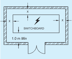
or TPN MCB to enable them to be disconnected from the supply.
5.3.6.8 Sufficient clearances as below shall be provided for isolating the switchboard to allow access for servicing, testing and maintenance (see Fig. 2):
a) A clear space of not less than 1 m in width shall be provided in front of the switchboard.
NOTE — In case the board has a shutter in the front for aesthetic reasons, provided the opening of the shutter shall satisfy the requirement of working/safety space of 1 m in front of the switchgear.
b) If there are any attachments or bare connections at the back of the switchboard, the space, if any, behind the switchboard shall be either less than 200 mm or more than 750 mm in width, measured from the farthest protruding part of any attachment or conductor.
c) If the space behind the switchboard exceeds 750 mm in width, there shall be a passageway from either end of the switchboard, clear to a height of 1.8 m.
d) If two switchboards are facing each other, a minimum distance of 2.0 m shall be maintained between them.
The connections between the switchgear mounting and the outgoing cable up to the wall shall be enclosed in a protection pipe.
There shall be a clear distance of not less than 250 mm between the board and the insulation cover, the distance being increased for larger boards in order that on closing of the cover, the insulation of the cables is not subjected to damage and no excessive twisting or bending in any case. The cable alley in the metal board should enable within prescribed limit twisting or bending of cable such that insulation of the cables is not subjected to damage.
In this connection, for installation of voltages exceeding 250 V, Regulation 37 of Central Electricity Authority (Measures Relating to Safety and Electricity Supply) Regulations, 2010, as amended from time-to-time shall also be complied with (see Annex B).
5.3.6.9 Sufficient additional space shall be allowed in substations and switchrooms to allow operation and maintenance. Sufficient additional space shall be allowed for temporary location and installation of standard servicing and testing equipment. Space should also be provided to allow for anticipated future extensions.
5.3.6.10 Panels in a room or cubicle or in an area surrounded by wall/fence, access to which is controlled by lock and key shall be accessible to authorized persons only.
Such installations shall be efficiently protected by fencing not less than 1 800 mm in height or other means so as to prevent access to the electric supply lines and apparatus therein by an undesignated person and the
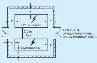
2B TWO SWITCH BOARDS/PANELS FACING EACH OTHER
X = Less than 200 mm (if switchboard/panel is not accessible from behind)
= More than 750 mm (if switchboard/panel is accessible from behind)
NOTE — X to be measured from the fathest protruding part of any attachment or conductor.
FIG. 2 CLEARANCES AROUND SWITCHBOARDS IN ENCLOSED ROOM
fencing of such area shall be earthed efficiently. Sufficient clearances as per 5.3.6.8 shall be provided between the switchboard and the wall/fence.
5.3.6.11 Except main LV panel, it will be preferable to locate the sub-panels/distribution boards/sub-meter boards near the load centre. Further, it should be ensured that these panels are easily approachable. The panels should have clear access from common areas excluding staircase.
Where the switchboard is erected in a room of a building isolated from the source of supply or at a distance from it, adequate means of control and isolation shall be provided both near the boards and at the origin of supply. Sufficient clearances as per 5.3.6.8 shall be provided.
5.3.6.12 All switchboards shall be of metal clad totally enclosed type or any insulated enclosed pattern.
| viii) | Negative of d.c. 2-wire circuit | Black |
| ix) | Outer (positive or negative) of d.c. 2-wire circuit derived from 3-wire system | Red |
| x) | Positive of 3-wire system (positive of 3-wire d.c. circuit) | Red |
| xi) | Middle wire of 3-wire d.c. circuit | Black |
| xii) | Negative of 3-wire d.c. circuit | Blue |
| xiii) | Functional earth-telecommunication | Cream |
1 Bare conductors are also used for earthing and earth continuity conductors. But it is preferable to use insulated conductors with green coloured insulation with yellow stripes.
2 As alternative to the use of red, yellow or blue colour may be used, if desired in large installations, up to the final distribution board. 3 For armoured PVC-insulated cables and paper-insulated cables, see relevant Indian Standard.
5.3.7.3 Colour, identification of cores of flexible cables and flexible cords {see also good practice [8-2(19)]} The colour of cores of flexible cables and flexible cords shall be in accordance with the following:
| Sl No.(1) | Number of Cores(2) | Function of Core(3) | Colour(s) of Core(4) |
|---|---|---|---|
| i) | 1 | PhaseNeutralProtective or earthing | Brown¹⁾(Light) BlueGreen and yellow |
| ii) | 2 | PhaseNeutral | Brown(Light) Blue¹⁾ |
| iii) | 3 | PhaseNeutralProtective or earthing | Brown(Light) Blue¹⁾Green and yellow |
| iv) | 4 or 5 | PhaseNeutralProtective or earthing | Brown or black¹⁾(Light) Blue¹⁾Green and yellow |