Part 8 Section 3Air Conditioning, Heating and Mechanical Ventilation
finally, the hand-over procedure were included.
Since the last revision of the Code in 2005, there has seen tremendous emphasis on energy conservation to meet the challenges posed by the climatic change. Hence the building design practices, the system components and principal equipment have gone through major development. The current revision fully recognizes the latest developments in the field of air conditioning, heating and mechanical ventilation.
The significant modifications made in this revision of this Section include amongst others, the following key changes:
a) Definitions of several new terms have been added relating to the new concepts introduced in this revision.
b) Clause on refrigerants has been modified to include new refrigerants with zero ozone depletion potential and ultra-low global warming potential. These are now manufactured in India and are commercially available, or are in advanced stage of development in the research and development laboratories. Water, Ammonia, CO₂ , and other natural refrigerants are making a comeback and are described with relevant details.
c) Planning considerations have been expanded to include the available options of variable refrigerant flow system; inverter technology, district cooling system, and hybrid central plant using chilled beams and radiant floor components. Planning clause also identifies the thrust on envelope optimization using energy modelling, day lighting simulation, solar shade analysis and wind modelling software to optimize the air conditioning load. Such buildings are thus designed to utilize the most energy efficient air conditioning system to bring the annual energy consumption to a minimum, which could be generated through renewable energy resources.
d) Outdoor design conditions for air conditioning load calculation and heating requirement have been based on the latest weather data tabulated for around 60 cities, covering all the five climatic zones of India. These are derived from the latest weather data taken from India Metrological Department, Government of India.
e) Indoor design conditions for comfort air conditioning, heating, and mechanical ventilation have been based on adaptive comfort conditions for the specific climatic zone, as per the procedure described in this completely revised clause.
The Committee explored the possibility of including heating degree day and cooling degree day in this Section. It was noted that at present, there was no scientific research in the country in public domain for arriving at heating degree day (HDD) and cooling degree day (CDD) of India and the same is being researched. It was also noted that suitable software tools were since available which provided better assessment of the cooling and heating requirements for the space. Therefore, heating degree day (HDD) and cooling degree day (CDD) was not included.
f) The central plant equipment clause has been revised to include active and passive chilled beams, radiant floor for cooling/heating of space, underfloor air distribution to minimise stratification, geo-thermal cooling and heating, and recently developed high-efficiency cooling towers with very low approach to ambient wet-bulb temperature.
g) Clauses on unitary/distributed equipment have been expanded and also direct/indirect evaporative cooling units have been included.
h) Provisions for specialized applications have been further detailed where provisions have also been now included for data centres and underground metro stations.
j) Refrigeration is common for summer air conditioning and for cold stores. Cold storage is key to India's food security by minimising food wastage. Therefore, a new clause has been introduced in this revision, on refrigeration for cold stores, describing the latest state-of-the-art technologies locally adopted.
k) Heating is required for indoor comfort conditions during winter months in northern part of India. This clause now describes the most efficient strategies for winter heating, using reverse cycle operation, solar heating systems, electric heat pump, and ground source heat pump.
m) Ventilation has now taken the centre-stage for sustainability in design, construction and operation of buildings. Natural ventilation and passive architecture are dealt in Part 8 ‘Building Services, Section 1 Lighting and Natural Ventilation’ of the Code, with further strategies for sustainable buildings covered in Part 11 ‘Approach to Sustainability’ of the Code. However, modern system of mechanical ventilation for industries, commercial kitchen, underground car parking, and for open tunnels connecting underground metro stations, has been now covered in this Section. It also covers demand control ventilation, where
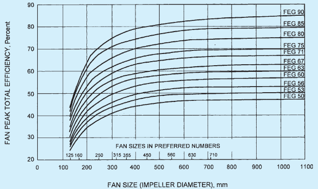
fresh air input for the control of indoor air quality, varies in direct proportion to the occupancy. Newly developed axial flow fans with aerofoil profile blades and acoustic silencers, has also been covered including criteria for solution of most efficient fan for the specific application.
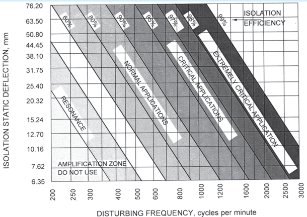
n) Installation practices for the air conditioning, heating and mechanical ventilation system have been modified to suit the vast options of components now available. The clause identifies the procedure and precautions to be taken for each major component of the central system; unitary/distributed systems; fan; ducting and piping support; and for insulation. Emphasis is laid on ease of maintenance/repair/replacement; for noise and vibration isolation, and for centralized monitoring and control through computerized building automation system.
p) Symbols, colour coding and identification of services clause has been modified to match with the international practices.
q) Measurement and verification of building performance is now widely practiced and has put strong emphasis on integrated building management system for modern building complexes. Therefore, the clause on building automation system has been upgraded to include the latest practices for web-based monitoring and control of performance parameters.
r) Testing, balancing, commissioning and handing over of the air-conditioning, heating and mechanical ventilation system clause has been extensively revised to include state-of-the-art procedures adopted.
This revision aims to make a difference in the quality of environment and in building usage, in response to growing concerns and expectations in with regard to indoor air quality, energy conservation, water conservation, environmental impact and building safety.
The provisions on natural ventilation are given in Part 8 ‘Building Services, Section 1 Lighting and Natural Ventilation’ of the Code.
The provisions of this Section are without prejudice to the various Acts, Rules and Regulations including The Factories Act, 1948 and the rules and regulations framed thereunder.
The information contained in this Section is based largely on the following Indian Standards:
IS 659 : 1964 Safety codes for air conditioning (revised)
(Part 1): 1992 Unitary air conditioners (second revision)
(Part 2): 1992 Split air conditioners (second revision)
IS 2379 : 1990 Colour code for identification of pipelines (first revision)
IS 3315 : 1994 Specification for evaporative air coolers (desert coolers) (second revision)
IS 8148 : 2003 Specification for packaged air conditioners (first revision)
Assistance has also been derived from the following publications in the preparation of this Section:
Guidelines, Standards and Handbooks of American Society of Heating, Refrigerating and Air Conditioning Engineers (ASHRAE)
Handbooks of Indian Society of Heating, Refrigerating and Air Conditioning Engineers (ISHRAE)
India Model for Adaptive Comfort, CEPT University, Ahmedabad
ISO 7730 : 2005 Ergonomics of the thermal environment Analytical determination and interpretation of thermal comfort using calculation of the PMV and PPD indices and local thermal comfort criteria
ISO 16484-1 : 2010 Building automation and control systems (BACS) Part 1: Project specification and implementation
All standards, whether given herein above or cross-referred to in the main text of this Section, are subject to revision. The parties using this Section are encouraged to investigate the possibility of applying the most recent edition of the standards.
1Scope
1.1 This Code (Part 8/Section 3) covers the planning, design considerations, installation, testing, commissioning and handing over and also operation and maintenance of air conditioning, heating and mechanical ventilation systems for buildings. It also covers refrigeration for cold storages.
1.2 The provisions of this Section aim to ensure an air conditioning, heating and mechanical ventilation system which can provide comfort by managing air temperature, humidity, indoor air quality and distribution of conditioned air for the specific use and occupancy of built space while giving due consideration to minimising energy consumption and other resources.
1.3 The provisions on natural ventilation are covered in Part 8 ‘Building Services, Section 1 Lighting and Natural Ventilation’ of the Code.
1.4 The provisions in respect of air conditioning, heating and mechanical ventilation system in sustainable buildings are covered in Part 11 ‘Approach to Sustainability’ of the Code, which shall be used in conjunction with this Section.
3Refrigerants
3.1 Refrigerants are classified into two classes based on their toxicity, namely Class A having lower chronic toxicity and Class B having higher chronic toxicity. They are classified into four classes based on their flammability, namely, Class 1 (no flame propagation), Class 2L (lower flammability), Class 2 (flammable) and Class 3 (higher flammability).
Refrigerants shall be designated and classified for safety in accordance with the accepted standard [8-3(2)].
3.1.1 Matrix Diagram of Safety Group Classification System
The toxicity and flammability classifications for refrigerants as per 3.1 yield eight safety groups, namely, A1, A2L, A2, A3, B1, B2L, B2 and B3. These safety groups are represented by the matrix shown below:
Toxicity →
Safety Group
Lower Toxicity
Higher Toxicity
Flammability ↓
Higher flammability
A3
B3
Flammable
A2
B2
Lower flammability
A2L
B2L
No flame propagation
A1
B1
3.2 While selecting refrigerants, manufacturers and designers shall adopt balanced approach considering environmental impact and human health. The key criteria that shall be considered are as follows:
a) Ozone depletion potential (ODP) — ODP of the refrigerant should preferably be zero and shall be as permitted under The Ozone Depleting Substances (Regulation and Control) Amendment Rules, 2014 as amended from time to time (see Note);
b) Global warming potential (GWP) — GWP of the refrigerant should preferably be low to reduce greenhouse gas (GHG) emissions, which is in line with the on-going discussion for phase-down of production and consumption of Hydrofluorocarbons (HFCs);
c) Refrigerant with zero ODP and low GWP should be adopted for balance approach considering overall environmental impact;
d) Flammability — The refrigerant should preferably be non-flammable/having flammability as low as possible, and suitable risk mitigation process/infrastructure (sensors, ventilation, etc) should be opted to mitigate the risk of flammability, if any, in line with the accepted standards;
2Terminology
For the purpose of this Section the definitions given below and those given in the accepted standard [8-3(1)] shall apply.
2.1 Air Conditioning — The process of treating air so as to control simultaneously its temperature, humidity, purity, distribution and movement and pressure to meet the requirements of the conditioned space.
2.2 Air System Balancing — Adjusting air flow rates through air distribution system devices, such as fans and diffusers, by manually adjusting the position of dampers, splitter vanes, extractors, etc, or by using automatic control devices, such as constant-air-volume or variable-air-volume (VAV) boxes.
NOTE — Air system should be balanced in order to minimise throttling losses. For fans, its speed should be adjusted to meet design flow conditions. By creating correct air flow at fans and outlet, system performance can be increased.
2.3 Atmospheric Pressure — The force per unit area exerted against a surface by the weight of the air above that surface. It is the pressure indicated by a barometer. Standard atmospheric pressure or standard atmosphere or barometric pressure is the pressure of 76 cm of
mercury column having a density of 13.595 1 g/cm³ under standard gravity of 980.665 cm/s² (10 332 mm of water column/101.325 kPa).
NOTE — Generally atmospheric pressure is used as a datum for indicating the system pressures in air conditioning and accordingly, pressures are mentioned above the atmospheric pressure or below the atmospheric pressure considering the atmospheric pressure to be zero. A ‘U’ tube manometer will indicate zero pressure when pressure measured is equal to atmospheric pressure.
2.4 Building Energy Simulation — Use of computer models for design and optimization of building's energy performance, to compare the cost-effectiveness of energy conservation measures in the design stage as well as assessing various performance optimization measures during the operational stage.
2.5 Building Integrated Renewable Energy — Integration of renewable energy application in parts of the building envelope such as the roof, skylights, or facades.
2.6 Building Management System (BMS) — An energy management system relating to the overall operation of the building in which it is installed. It often has additional capabilities, such as equipment monitoring, protection of equipment against power failure, and building security. It may also be a direct digital control (DDC) system where the mode of control uses digital outputs to control processes or elements directly.
4.3Equipment Room for Central Air Conditioning Plant
4.3.1 This room shall be located preferably within the building being air conditioned and closer to external wall for facilitating ventilation and equipment movement. The equipment may also be installed in a separate service block which should also be located as close as possible to the load/building being conditioned. The clear headroom below soffit of beam should be minimum 4.5 m for larger capacity chillers (500 TR and above) and minimum 3.6 m for smaller plants.
4.3.2 The floors of the equipment rooms should be finished smooth. For floor loading, the air conditioning engineer should be consulted (see also Part 6 'Structural Design, Section 1 Loads, Forces and Effects' of the Code).
4.3.3 Supporting of pipe within plant room spaces should be normally from the floor. However, outside plant room areas, structural provisions shall be made for supporting the water pipes from the floor/ceiling slabs. All floor and ceiling supports shall be isolated from the structure to prevent transmission of vibrations.
4.3.4 Equipment rooms, wherever necessary, shall have provision for mechanical ventilation. In hot and dry climate, evaporative air cooling may also be considered.
4.3.5 Plant machinery in the plant room shall be placed on levelled plain/reinforced cement concrete foundation block and provided with anti-vibratory supports or alternatively on inertia bases. Supports for appliances shall be designed and constructed to sustain vertical and horizontal loads within the stress limitations specified in the Part 6 ‘Structural Design’ of the Code. All foundations should be protected from damage by providing epoxy coated angle nosing. Seismic restraints requirement should also be considered (see also 12.6.4).
4.3.6 Appropriate sound insulation and noise control measures shall be taken in plant room space as per
Part 8 ‘Building Services, Section 4 Acoustics, Sound Insulation and Noise Control’ of the Code. Acoustic treatment as may be required shall be provided in plant room space in accordance with 12.1.9 to prevent noise transmission to adjacent occupied areas.
4.3.7 In case air conditioning plant room is located in basement, equipment movement route shall be planned to facilitate future replacement and maintenance. Service ramps or hatch in ground floor slab should be provided in such cases. Fire egress and emergency battery backup lighting shall be provided for the plant room operator.
4.4Equipment Room for Air Handling Units and Package Units
4.4.1 This shall be located as centrally as possible to the conditioned area and contiguous to the corridors or other service areas for carrying air ducts in ceiling spaces.
4.4.2 In case of special and high-rise buildings, air handling units shall be provided in accordance with Part 4 ‘Fire and Life Safety’ of the Code. Air handling unit rooms should preferably be located vertically one above the other.
4.4.3 Provision shall be made for the entry of outdoor ventilation air into air handling unit room. For energy
conservation, it is desirable to install mechanism for modulating the outdoor air quantity based on demand.
4.4.4 Exterior openings for outdoor air intake and also exhaust outlets shall have louvers having rain protection profile, with volume control damper, pre-filter and bird screen.
4.4.5 In all cases, outdoor air intakes shall be so located as to avoid contamination from exhaust outlets and from the sources in concentration greater than normal in the locality in which the building is located. It is recommended to maintain minimum 8 m separation between outdoor air intake points and exhaust outlets.
4.4.6 Exhaust air from any dwelling unit shall not be circulated/ingress directly or indirectly to any other dwelling unit, to public corridor or into public stairway.
4.4.7 All air handling rooms should have floor drains and if possible, water supply connection. The trap in floor drain shall provide a water seal between the air conditioned space and the drain line.
4.4.8 Supply/return air duct serving other areas shall not be taken through fire exits.
4.4.9 Waterproofing of air handling unit rooms shall be carried out to prevent damage to floor below.
4.4.10 The floors should be finished smooth. For floor loading, the air conditioning engineer should be consulted (see also Part 6 ‘Structural Design, Section 1 Loads, Forces and Effects’ of the Code).
4.4.11 Structural design should avoid beam obstruction to the passage of supply and return air ducts. Adequate ceiling space should be made available outside the air handling unit room to permit installation of supply and return air ducts and fire/smoke dampers at compartment wall crossings.
4.4.12 Appropriate sound insulation and noise control measures shall be taken in air handling unit rooms, if located in close proximity to occupied areas, as per Part 8 ‘Building Services, Section 4 Acoustics, Sound Insulation and Noise Control’ of the Code. The air handling unit rooms shall be acoustically treated in accordance with 12.1.9, if located in close proximity to occupied areas.
4.6Supply Air Ducts and Return Air Ducts
4.6.1 The duct supports shall be designed to handle the load and also to take into account seismic considerations. The support material should be galvanized steel/aluminium and facilitate ease of installation at site using alternatives such as fully threaded rod/angle section/wire support systems using stud anchors provided in the ceiling slab from drilled holes without damaging the slab or structural member.
4.6.2 If false ceiling is provided, the supports for the duct and the false ceiling, shall be independent. Collars for grilles and diffusers shall be taken out only after false ceiling/boxing framework is done and frames for fixing grilles and diffusers have been installed. Flexible ducts may be used for making the final connections.
4.6.3 Where a duct penetrates the masonry wall, it shall either be suitably covered on the outside to isolate it from masonry, or an air gap shall be left around it to prevent vibration transmission. Further, where a duct passes through a fire resisting compartment/barrier, the annular space shall be sealed with fire sealant to prevent smoke transmission (see Part 4 'Fire and Life Safety' of the Code).
4.7Cooling Tower
4.7.1 Cooling towers are used to dissipate heat from water cooled refrigeration, air conditioning and industrial process systems to the atmosphere. Cooling is achieved by evaporating a small proportion of recirculating water into outdoor air stream. Cooling towers shall be installed at a place where free flow of atmospheric air is available.
4.7.2 Range of a cooling tower is defined as temperature difference between the entering and leaving water. Approach of the cooling tower is the difference between leaving water temperature and the ambient air wet-bulb temperature.
4.7.3 Selection of Cooling Tower
Following factors shall be considered for selection of cooling tower:
a) Design wet-bulb temperature and approach of cooling tower. The designer shall endeavour for reducing the approach for maximizing the energy conservation potential;
b) Height limitation and aesthetic requirement;
c) Location of cooling tower considering possibility of easy drain back from the system;
d) Placement with regard to adjacent walls, windows and other buildings, and effects on these from any water carried over by the air stream;
e) Vibration and noise levels, particularly during silent hours;
f) Material of construction for the tower;
g) Direction and flow of prevailing wind;
h) Quality of water used for make-up;
j) Maintenance and service space availability; and
k) Ambient air quality.
4.7.4 The recommended floor area requirement for various types of cooling tower is as given below:
a) Natural draft : 0.15 to 0.20 m²/TR cooling tower
b) Mechanical draft : 0.07 to 0.10 m²/TR cooling tower
4.7.5 Structural provision for the cooling tower shall be taken into account while designing the building. Vibration isolation shall be an important consideration in structural design.
4.7.6 Special care should be taken in design where noise transmitted to the adjoining building can be of serious concern. Special vibration control and sound attenuation devices may be required in that case. Appropriate sound insulation and noise control
measures shall be taken in such cases in accordance with Part 8 ‘Building Services, Section 4 Acoustics, Sound Insulation and Noise Control’ of the Code.
4.7.7 Certain amount of water is lost from circulating water in the cooling tower, as given below:
6.2Design of Indoor Conditions as per Adaptive Thermal Comfort Model
Air conditioning systems for interior spaces intended for human occupancy shall be sized for not more than 26° C for cooling and for not less than 18° C for heating at occupied level.
Design based on an adaptive thermal comfort model can play a major role in reducing energy use whilst maintaining the comfort, productivity and well-being of occupants. This approach recognizes that people's thermal comfort needs depend on their past and present context and that these needs vary with the outdoor environmental conditions of their location. People living year-round in air conditioned spaces are likely to develop high expectations for homogeneity and cool temperatures, and may become quite critical if thermal conditions deviate from the centre of the comfort zone they have come to expect. In contrast, people who live or work in naturally ventilated buildings, are able to control their immediate interior spaces, get accustomed to variable indoor thermal conditions that reflect local patterns of daily and seasonal climate changes. Their thermal perceptions, preferences as well as tolerances are likely to extend over a wider range of temperatures. It allows buildings to operate within broader temperature bands. The specification of a broader comfort band suited to the Indian context has the potential to reduce the use of energy intensive space cooling for buildings in India.
This Section deals with adaptive thermal comfort model
which differentiates the thermal response of occupants in air conditioned and naturally ventilated buildings. It is imperative to specify indoor comfort conditions separately for buildings depending upon their operation, namely, air conditioned buildings as well as naturally ventilated buildings.
Operative temperature is more suitable index to measure thermal comfort in the building having low indoor air velocities, since the index also accounts for impact of building surface temperatures (radiant temperatures) on human comfort. Indoor operative temperature, for sedentary activities, can be approximated as an arithmetic mean of indoor air and radiant temperatures. For operating air conditioning system based on operative temperature, the prevalent conditions along with the historical outdoor trend can be used to derive suitable operative temperature limits. Typical climatic conditions of various Indian cities is in public domain.
7Design of Air Conditioning
7.1 General
Systems for air conditioning need to control temperature, humidity and air quality within predetermined limits throughout the year. Systems for air conditioning may be grouped as all-air type, air and water type, all-water type and unitary type. Suitability of system type cannot be generalized; it needs to be building specific decision considering, initial cost, efficiency, maintenance, effect on building aesthetics, noise, service life and other factors. Lower operating cost, central maintenance and control are primary considerations. Designers may select centralized systems that comprise DX units or chillers and cooling towers (as applicable), all housed away from occupied spaces. This mitigates noise impacts. The heating application may require heat pumps or boilers.
These systems often require a greater initial cost than distributed systems but often result in annual energy savings because additional benefits also include the ability to reduce installed capacity by using load diversity. Centralized cooling systems usually prove to be more cost-effective when the total building load exceeds 100 TR, depending on climate and patterns of occupancy use. Central heating systems are desirable in heating applications in many building sizes since they can provide closer space control and can be used with many types of terminal units.
When low initial cost and simplicity are primary concerns, designers may select zone-by-zone distributed systems, incorporating either cooling or both heating and cooling facility. This approach tends to be used for smaller buildings as well as for larger buildings with multiple tenancy and sufficient roof area. Distributed equipment consists of fan, cooling coil, compressor and outdoor condenser. Examples of distributed systems include unitary air conditioners, packaged rooftop air conditioners, variable refrigerant flows (VRFs), heat pumps, as well as refrigerant-based split-system fan-coil units (single or multi-unit). Water-source heat pumps (WSHPs) are also distributed systems in which the compressor is located close to the occupied space, but they are collectively served by a centralized water system with auxiliary heat rejection devices.
6.3Indoor Air Quality (IAQ)
Indoor air quality is the quality of air which affects our comfort and health. This is most directly related to health and may result in sick building syndrome (SBS). Poor indoor air quality results in severe and recurring discomforts such as nausea, headaches, cold, dry mucous, inflamed membrane eye, nose and throat irritation, drowsiness, fatigue, dry skin and respiration problems.
6.3.1 Measure of Indoor Air Quality (IAQ)
Carbon dioxide is used as a surrogate ventilation index for diagnosing the ventilation efficiency in an air conditioned area. The measurement of carbon dioxide inside a conditioned area is an indicator of IAQ. Odour criteria are likely to satisfy, if ventilation rates are set so that 1 000 ppm CO₂ is not exceeded. However, in situations where outdoor conditions are not favourable, a difference of 700 ppm, where indoor ppm are less than outdoors, should be targeted. Building should meet accepted standards to avoid contamination through volatile organic compounds, microbial contamination (fungal and bacteria).
6.3.2 Components of Acceptable Indoor Air Quality (IAQ)
Acceptable IAQ is typically not achieved by addressing any one specific building product, system or procedure;
Table 3 Minimum Ventilation Rates in Breathing Zone (See Notes 1 to 5)
[Clause 6.2(c)(3)]
(This table is not valid in isolation; it shall be used in conjunction with the accompanying notes.)
Sl No.
Occupancy Category
People Outdoor Air Rate, Rp
Area Outdoor Air Rate, Ra
Notes
Default Values
Air¹⁾ Class
cfm/person
l/s.person
cfm/ ft²
l/s. m²
Occupant Density (see Note 4)
Combined Outdoor Air Rate (see Note 4)
Persons per 1 000 ft² or per 100 m²
cfm/person
l/s.person
(1)
(2)
(3)
(4)
(5)
(6)
7.3Factors to be Considered for Different Applications
The general guidance, for various selected applications, for the factors that usually influence the selection of the type, design and layout of the air conditioning or ventilating system, to be used are given in 7.3.1 to 7.3.6. The primary objective of these is to define the special provisions required for the air conditioning system, to ensure comfort conditions for occupants in the respective applications.
7.3.1 Office Building
Office building may include both the outer and inner zones. The outer zone may be considered as extending from approximately 4 m to 6 m inwards from the outer wall of the building, and is generally subjected to wide load variation owing to daily and annual changes in outside temperature and solar radiation. Ideally, the system(s) selected to serve an outer zone should be able to provide summer cooling and winter heating. During intermediate seasons the outer zone of one side of the building may require cooling and at same time the outer zone on another side of the building may require heating. The main factors affecting load are usually window area and choice of shading devices.
The other important factors are the internal gain owing to people, light and office equipment. Choice of system may be affected by requirements to counteract downdraughts and chilling effect due to radiation associated with single glazing during winter. Cooling load for inner zone is generally entirely from the heat gain from people, lights and office equipment, which is generally fairly uniform throughout the year.
Other important considerations in office building application may include requirements for individual room control, partitioning flexibility serving multiple tenants, and requirement of operating selected areas outside of normal office hours. Areas such as conference room, board room, canteens, etc, will often require independent system. For outer building zone with large glass area, for example, greater than 60 percent of the external facade, the air-water type of system, such as induction or fan coil is generally economical than all-air system and has lower space requirement. For outer zones with small glass area, an all-air system, such as variable volume, may be the best selection. For building with average glass area, other factors may determine the choice of system. For inner zone, a separate all-air system with volume control may be the best choice. System employing reheat or air mixing, while technically satisfactory, is generally poor as regards energy conservation.
8.1.2Data Centre
8.1.2.1 Data centre is a technological facility which houses electronic equipment used for data processing, storing and networking (datacom equipment). The design requirement for cooling of such technological facility differs significantly from comfort air conditioners.
Such facility has a little or no requirement of occupancy as the facility becomes complete automatic barring interventions for maintenance. The major contributing heat is from electronic equipment which is sensible in nature and hence cooling equipment needs to be designed with a high sensible factor. Main focus is equipment cooling rather than comfort conditions for space.
The facility generally works for all day and all night (continuously 24 × 7 ). High reliability and redundancy is an important criteria as any loss of data may contribute to huge financial loss. The components to be selected for cooling datacom equipment need to be highly reliable besides being energy efficient.
8.1.2.2 Inside conditions/thermal guidelines
Inside temperature within the facility may vary depending on whether dehumidified conditioned air is supplied on inlet side or exhaust side of the equipment. Presently the best practice of facility design for datacom equipment placement in the rack is based on hot and
cold aisle air arrangement. In such configuration, front of the datacom equipment cabinet/rack should face cold aisle, where the dehumidified conditioned air from cooling equipment is supplied either through floor grilles or through overhead ducts.
The allowable envelope is where information technology (IT) manufactures test their equipment in order to verify that the equipment will function within these envelope boundaries.
Prolonged exposure of IT equipment to conditions outside its recommended range, especially approaching the extremes of the allowable environment, can result in decreased equipment reliability and shorter life span. However, occasional short time excursions outside the allowable envelope, may be acceptable.
Facilities should be designed and operated to target the recommended range. The present recommended range is:
a) Low end temperature : 18°C (64.4°F)
b) High end temperature : 27°C (80.6°F)
c) Low end moisture : 5.5°C DPD
d) High end moisture : 60 percent RH and 15°CDP (59°FDP)
8.1.1Health Care Facility
Patient therapy shall be the prime consideration while air conditioning or ventilating a health care facility. While planning the air conditioning and ventilation of the health care facility, the plan shall include the clinical services to be provided in each space, equipment to be used with in the space and requirement of temperature, humidity, air flow pattern and pressure gradient with respect to adjacent spaces.
Following are the parameters which shall be taken into consideration while designing HVAC system for health care facilities:
a) Temperature and humidity requirements of various spaces;
b) Ventilation and filtration requirements for contamination control;
c) Restriction on air movement between adjoining spaces;
d) Permitted tolerance on environmental conditions;
e) System reliability and maintainability; and
f) Adaptability of the system for fire emergency and for smoke management.
Guidelines for the above parameters for various functional spaces in a health care facility are given in Table 6 and Table 7.
8.1.1.1 Air distribution system
Air distribution systems in a health care facility shall provide ventilation to dilute and remove contaminants and assist in controlling transmission of air borne infections besides maintaining the desired temperature and humidity. Design of the air distribution system shall be such that air movement is from clean to less clean areas. Recirculation of air should be avoided in critical care areas.
For critical care areas, constant volume systems shall be used to maintain proper pressure relations and ventilation. Critical areas in general are operating theatres, ICUs, isolation rooms, sterile areas, postoperative patient care; any place which houses medical surgical procedures and some of the laboratories.
For patient rooms and non-critical areas, variable air volume system shall be considered for energy conservation. However when variable air volume systems are used, care should be taken to ensure that minimum ventilation requirements are not compromised and pressure balance is maintained even at minimum flow.
Active smoke control systems shall be used along with fire and smoke partitions to limit the spread of smoke in the event of fire. Smoke and fire management shall be done in accordance with Part 4 ‘Fire and Life Safety’ of the Code. For health care facilities which provide ambulatory care to patients, safety from fire and smoke is a paramount design consideration and shall be provided in accordance with Part 4 ‘Fire and Life Safety’ of the Code.
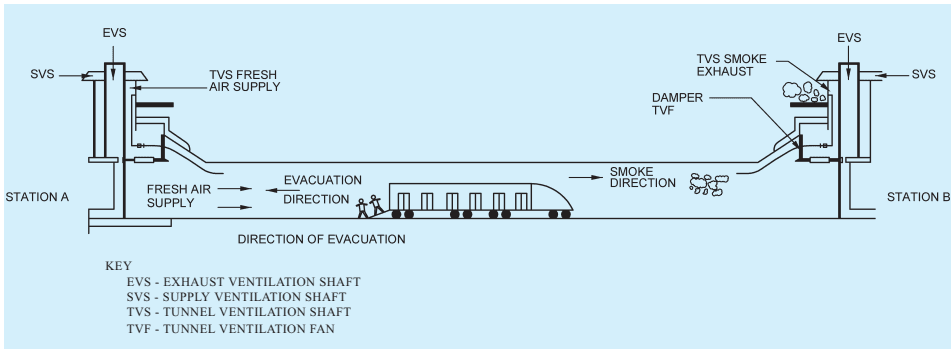
8.1.3Underground Metro Station
The underground metro station is provided with environment control system (ECS). The ECS system shall serve following function:
a) Station public area and ancillary room air conditioning,
b) Mechanical ventilation of plant rooms, and
c) Smoke management system.
8.1.3.1 Station public area and ancillary room air conditioning
8.1.3.1.1 Station air conditioning design philosophy
The underground stations of the metro corridor are built in a confined space. A large number of passengers occupy concourse halls and the platforms, especially at the peak hours. It is therefore, essential to provide forced ventilation in the stations for the purpose of,
a) supplying fresh air for the physiological needs of passengers and the authority's staff;
b) removing body heat, obnoxious odours and harmful gases like carbon dioxide exhaled during breathing;
c) preventing concentration of moisture generated by body sweat and seepage of water in the sub-way; and
d) removing large quantity of heat dissipated by the train equipment like traction motors,
44
braking units, compressors mounted below the under-frame, lights and fans inside the coaches and the air conditioning units.
8.1.3.1.2 Station heat load
The station heat loads are a combination of the unsteady train heat loads, passenger heat load, lighting, equipment, miscellaneous equipment and fresh air loads, as given below:
a) Unsteady heat load due to train movement — The major source of heat for the station is from the train air conditioning systems and the train traction and braking systems.
The heat developed inside the tunnel during normal operation mixes with station air due to piston effect caused by train movement. This increases heat load of the station. This heat load is unsteady and needs special software for its estimation. These software model the complete metro network of tunnels and underground station and take train operation, rolling stock physical parameter, tunnel structure parameters, tunnel gradient and alignment, station architecture, etc, as input data. Such software takes into account the heat load of tunnel airflow generated by the train movement and the heat of trains dwelling at station as per the planned headway of train operation. These values do not include the fresh air heat loads or the steady heat loads from station, such as passengers, lighting, escalator and other equipment.
10Heating
10.1 The installations for air conditioning system may be used advantageously for the central heating system with additions such as a hot water and hot water coil or a strip heater bank. Electrical heating may be actively discouraged and instead heating through superheat of cooling unit, heat pump, reverse cycle operation of unitary system and solar hot water systems are highly desirable; these result in a greener environment and lower carbon foot print.
While the efficiency of a heating equipment can never be more than 100 percent, a refrigeration system for heating usage can have the coefficient of performance (COP) of more than 4.5. Therefore, compared to electrical heating or thermal heating through boiler, preference should be for the systems working on refrigeration principle. Some examples are heat pump, VEF system, air cooled package unit, split air conditioner (in reverse cycle mode), and even window air-conditioner (in reverse cycle mode). Any of these refrigeration system can result in considerable energy saving and lesser carbon print. Hence while purchasing an air conditioner, a better choice can be for models with both cooling-heating modes.
10.2 Various heating equipment/systems are described under 10.2.1 to 10.2.6.
10.2.1 Hot Water Heated Coils
Central heating systems using hot water usually require not more than one or two rows of tubes in the direction of air flow, in order to produce the desired heating capacity. To achieve high efficiency without excessive water pressure drop through the coil, various circuit arrangements are adopted.
Generally, the resistance to the hot water flow through the heating coil should not exceed 4kPa in low pressure
hot water heating installations. In high pressure hot water installations, the resistance to the water flow will probably be determined by other factors, for example, the need to balance circuits.
The hot water heating coil should be served from hot water supply and return mains with sufficient connections to each row, or bank of tubes, or sections, to give uniform distribution of the heating medium.
The hot water supply connection to the heating coil should generally be arranged at the lowest point, and the return connections at the highest, to aid venting. The expansion of the tubes when the heating coil is in operation should be considered, and necessary arrangement made to accommodate expansion and contraction.
Thermometer wells should be fitted in the pipes near the inlet and outlet of the coil so that the temperature drop through the heating coil can be readily observed.
9Refrigeration for Cold Stores
Cold store plays a major and critical role in cold chain. Apart from required temperature and relative humidity management, better air movement around the produce, proper arrangement of stacking, inspecting for any defectives are also important to maintain the produce quality in cold storage. The two basic product groups on cold storage of perishable food stuffs are chilled food and frozen food. The material of the equipment/
machineries used in cold stores should be corrosion resistant property and easily accessible for maintenance.
9.1 Key Elements and Components of Cold Room
9.1.1 Product Quality
Refrigeration cannot improve the quality of products. It does slow down the processes of microbial, chemical or enzymatic deterioration that occur in them. The more advanced these processes are, the more difficult it is to slow them down. Good results can, therefore be, expected only with clean, wholesome products which are free of any bruises, contamination or physiological disorders, and which have a normal microbial population for the products.
Storing products which do not have these qualities can harm those that do, when they are stored in the same room. They can also contaminate the rooms in which they are put together, through odours, dispersal of mold spores, etc. It shall be kept in mind that harmful micro-organism development can begin after a certain length of time and then speed up considerably. It is often very useful to know exactly where the product has come from and its history, in order to better evaluate its long term keeping quality, from both a qualitative and a commercial point of view.
Cold treatment should come quickly; that is, it should be done as soon as possible after the raw products have been harvested. Any delay in storing a product reduces the amount of time it can be stored, either because it has already deteriorated, or because it has already been transformed, and putting it into cold storage may not keep it from deteriorating further. Refrigeration should be continuous.
9.1.2 Temperature of Cold Room
During the entire storage period, the temperature should remain as constant as possible. Some products are particularly sensitive to temperature variations, which can reduce the shelf life of some fruits.
One shall avoid putting into a room a large amount of goods at a temperature too different from that of goods already in the room. The cold-production equipment should be checked to make sure it can handle this extra load. Within one room the temperature should be as uniform as possible, as this affects not just products that are sensitive to temperature variations, but also those with recommended temperatures near 0° C. These optimum conditions shall be approachable without risk of freezing.
11Mechanical Ventilation
11.1 Objective and Options
Ventilation is the process of changing air in an enclosed space. A portion of the air in the space should be continuously withdrawn and replaced by fresh air drawn from outside to maintain the required level of air purity, health, comfort and safety of building occupants. Ventilation is required to control the following:
a) Oxygen content — Prevent depletion of the oxygen content of the air;
b) Carbon dioxide and moisture — To prevent undue accumulation;
c) Other hazardous gases, such as, CO, NOx, SO₂, etc — To eliminate;
d) Odours and contaminants — To prevent undue rise in concentration of body and other odours and contaminants (chemical, VOCs, tobacco smoke, etc);
e) Bacteria — To oxidize colonies of bacteria and fungi to prevent their proliferation; and
f) Heat — To remove body heat and heat dissipated by electrical or mechanical equipment, and solar heat gains.
Ventilation may include either mechanical exhaust system or exhaust can occur through natural means. Mechanical ventilation is one of the forms of ventilation option available. It usually consists of fans, filters, ducts, air diffusers and outlets for air distribution within the building. Natural ventilation and natural exhaust, which are another option for ventilation, are covered in Part 8 ‘Building Services, Section 1 Lighting and Natural Ventilation’ of the
Code. The scope of this Section is therefore restricted to mechanical ventilation.
Following considerations affect the type of ventilation system selected for a particular application and sizing of the ventilation plant:
a) The climatic zone in which the building is located is a major consideration. An important distinction that shall be made is between hot-dry and warm-moist conditions. In an industrial environment, hot dry conditions occur around furnaces, forges, metal extruding and rolling mills, glass forming machines, and so forth.
Typical warm moist conditions are found in textile mills, laundries, dye houses, and deep mines where water is used extensively for dust control. Warm-moist conditions are more hazardous than hot-dry conditions.
b) Siting (and orientation) of a building is also an important factor. Solar heat gain and high outside temperature can add significant heat load, in addition to the internal heat gains from occupants, equipment and processes.
7.2Design Considerations
7.2.1 System Analysis and Selection
System selection for occupant comfort, as defined in 6, for space cooling, heating and ventilation, shall be based on the following criteria:
Temperature and its acceptable variation,
Humidity and its acceptable variation,
Air movement,
Air purity or quality,
Air changes per hour,
Air and/or water velocity requirements,
Local climate,
Space pressure requirements,
Capacity requirements as per load calculation analysis,
Redundancy,
Spatial requirements,
Fire safety and security concerns,
Initial cost,
Operating cost, including energy and power costs,
Maintenance cost,
Reliability,
Flexibility,
Controllability,
Life-cycle analysis,
Sustainability characteristics,
Acoustics and vibration, and
Mold and mildew prevention.
7.2.1.1 Types of systems
Comparative advantages, disadvantages and constraints of each option should be carefully evaluated before zeroing down to final HVAC system selection. Table 5 lists out various system characteristics of different HVAC systems; the same may be used as a tool for system analysis and selection.
When accurate temperature control is needed, constant volume systems shall be used. Dehumidification arrangement and return air bye-pass shall be included while designing constant volume system. When using high velocity system, dual ducting shall be provided.
7.2.2 The requirements for various air conditioning equipment/system are given in 7.2.3 to 7.2.15.
7.2.3 Central Chilled Water System — Types and Components
7.2.3.1 The central chilled water system equipment selection criteria shall be based on a comprehensive study to evaluate and define the lowest life-cycle cost
e) Toxicity — The refrigerant should have toxicity as low as possible, and suitable risk mitigation strategies/infrastructure (sensors, ventilation, etc) should be opted to handle toxicity, if any in line with the accepted standards; and
f) The refrigerant should also support other key performance parameters, including high energy efficiency, low emissions, chemical and thermal stability and material compatibility.
NOTE — The production and consumption of ozone depleting substances (ODS) including HCFCs, for example, HCFC-22 and HCFC-123 is being phased out by 2030. The import of refrigeration and air conditioning equipment containing HCFCs has already been banned from 01 July 2015, and the manufacturing of all such equipment with HCFC will be banned in the country from 01 January 2025 in accordance with The Ozone Depleting Substances (Regulation and Control) Amendment Rules, 2014.
For ODP, GWP and safety group (flammability and toxicity) of different refrigerants, reference shall be made to Table 1. As there are ongoing developments with respect to refrigerants with HCFC Phase-out Management Plan (HPMP) and HFC phase down proposals, latest regulations applicable at the time of selection of equipment/systems with various possible refrigerants shall be followed. As research is going on for alternative refrigerants to various HCFC/HFC/HFO refrigerants, it is recommended that project teams should make a conscious effort to select equipment/systems with refrigerant with high energy efficiency, least negative impacts on health, safety and environment as per the latest developments.
Table 1ODP and GWP Values (100 Year Values) and Safety Group of Different Refrigerant Types (Clause 3.2)
3.3 Suggested list of refrigerants which may be used for various applications is given below (see also Note under 3.2):
a) Air conditioning:
Residential, small unitary light commercial, VRF application — R-22, R-32, R-410A, R-452B and R-290.
Chillers for comfort, industrial and process application — R-123, R-134a, R-245fa, R-407C, R-513A, R-1233zd(E), R-514A, R-1234ze(E), R-1234yf, R-717 and R-718.
Transport, mobile application — R-134a, R-407C and R-1234yf.
b) Refrigeration:
Stationary and transport, mobile application — R-744, R-717, R-404A, R-452A, R-134a, R-290.
NOTE — Mechanical and electrical equipment installed in the building, such as, air conditioning, ventilation, lighting, lifts, power, pumping stations, fire fighting systems, security systems are controlled and managed through BMS.
2.7 Buildings Related Illnesses (BRI) — The diagnosable illness attributed directly to the specific air-borne building contaminants, like Legionnaire's disease, occupational asthma, etc.
NOTE — Indicators of BRI include complaints of cough, chest tightness, chills, fever and muscle aches. Occupants may need prolonged recovery times after leaving the building.
2.8 Coefficient of Performance, Compressor, Heat Pump — Ratio of the compressor heating effect (heat pump) to the rate of energy input to the shaft of the compressor, in consistent units, in a complete heat pump, under designated operating conditions.
2.9 Coefficient of Performance, Compressor, Refrigerating — Ratio of the compressor refrigerating effect to the rate of energy input to the shaft of the
compressor, in consistent units, in a complete refrigerating plant, under designated operating conditions.
2.10 Coefficient of Performance (Heat Pump) — Ratio of the rate of heat delivered to the rate of energy input, in consistent units, for a complete operating heat pump plant or some specific portion of that plant, under designated operating conditions.
2.11 Coefficient of Performance (Refrigerating) — Ratio of the rate of heat removal to the rate of energy input, in consistent units, for a complete refrigerating plant or some specific portion of that plant, under designated operating conditions.
2.12 Cooling Load — Amount of cooling per unit time required by the conditioned space or product; or heat that a cooling system shall remove from a controlled system over time.
2.13 Cooling Tower — An enclosed device, often tower like, for evaporatively cooling water by contact with air.
2.14 Dedicated Outdoor Air System (DOAS) — A unit that is used to separately condition outdoor air brought into the building for ventilation or to replace air that is being exhausted.
2.15 Demand Based Ventilation — Intelligent airflow management that adjusts outside ventilation air based on the number of occupants and the ventilation demands that those occupants create.
2.16 Design Pressure Difference — The desired pressure difference between a given space and an adjacent space measured at the boundary of the given space under a specified set of conditions, such as, that required in various spaces of hospital, clean rooms, protected space in case of smoke control operation, etc.
2.17 Dew Point Temperature — The temperature at which condensation of moisture begins when the air is cooled at same pressure.
2.18 Dry-Bulb Temperature — The temperature of the air, read on a thermometer, taken in such a way as to avoid errors due to radiation.
2.19 Duct System — A continuous passageway for the transmission of air which, in addition to the ducts, may include duct fittings, dampers, plenums, grilles and diffusers.
2.20 Economizer, Air — It consist of duct, damper and control system that allow outside air to cool the building when outside air is cooler than inside.
2.21 Economizer, Water — In this system the supply air of a cooling system is cooled indirectly with water
that is itself cooled by heat transfer or mass transfer to the environment without the use of mechanical cooling.
2.22 Effective Temperature — Combined effects of air temperature, humidity, air movement, mean radiant temperature, clothing and activity on the sensation of warmth or cold felt by the human body. Numerically equivalent to the temperature of still air producing similar thermal sensation as produced by combination of above six parameters of thermal comfort.
2.23 Energy Efficiency Ratio (EER) — Ratio of net cooling capacity in BTU/h to total rate of electric input in watts under designated operating conditions.
2.24 Energy Recovery Unit — A heat exchanger assembly for transferring energy between two isolated fluid sources. The recovery system may be of air-to-air design or a closed loop hydronic system design. The system will include all necessary equipment, such as fans and pumps, associated ducts or piping and all controls (operating and safety), and other custom-designed features
2.25 Evaporative Cooling — The process of evaporating part of a liquid by supplying the necessary latent heat from the sensible heat of the main bulk of the liquid which is thus cooled.
2.26 Fire Damper — The damper, normally held open, installed in an air distribution system or in a wall or floor assembly and designed to close automatically in the event of a fire in order to maintain the integrity of the fire separation.
2.27 Geothermal Heat Pump — A heating and/or cooling system utilizes the earth's crust, as heat source (in the winter) or a heat sink (in the summer) by using fluid to be pumped into the earth and circulated in order to exchange heat for the purpose of heating or cooling applications
2.28 Global Warming Potential (GWP) —The relative measure of how much a given mass of a refrigerant contributes to global warming over a given time period compared to the same mass of carbon dioxide over the same period.
NOTE —The GWP value of carbon dioxide is taken to be 1.0. The GWP value of a refrigerant is calculated over a time horizon. The time horizon can greatly affect the numerical value of GWP. Usually the GWP values are reported over a 100 years' time horizon.
2.29 Heating Load — Heating rate required to replace heat loss from the space being controlled.
2.30 Heat Pump — A thermodynamic heating/ refrigerating system to transfer heat. The condenser and evaporator may change roles to transfer heat in either direction. By receiving the flow of air or other fluid, a heat pump is used to cool or heat. Heat pumps may be
8
the air source with heat transfer between the indoor air stream to outdoor air or water source with heat transfer between the indoor air stream and a hydronic source (ground loop, evaporative cooler, cooling tower, or domestic water).
2.31 Heat Recovery — Use of heat that would otherwise be wasted from a system or process, for example, heat-recovery chiller which uses hot waste gases as a heat source.
2.32 Hybrid Building — A building which contains both active and passive systems of heating or cooling. It requires small amount of non-renewable energy to maintain required amount of coefficient of performance (COP).
2.33 Hydronic Systems — The water systems that transfer heat to or from a conditioned space or process with hot or chilled water. The water flows through piping that connects a chiller or the water heater to suitable terminal heat transfer units located at the space or process.
2.34 Hydronic System Balancing — Adjusting water flow rates through hydronic distribution system devices, such as pumps and coils, by manually adjusting the position valves or by using automatic control devices, such as automatic flow control valves.
2.35 Indirect-Direct Cooling — The cooling which involves the following two stages:
a) The first stage, in which the air is made to pass through heat exchanger for sensible cooling (no direct contact of air and water), whereby the leaving air dry-bulb temperature (DBT) as well as the wet-bulb temperature (WBT) are reduced; and
b) The second stage, in which the air after the first stage is made to pass through the evaporative air-cooling (adiabatic cooling) application where water and air are in direct contact and there is simultaneous removal of sensible heat and the addition of moisture to the air giving lower DBT.
2.36 The resultant of this two stage cooling is that the leaving air DBT is lower than ambient WBT.
NOTE — The first stage cooling is through indirect cooling. In this method, air-dry bulb and wet-bulb temperature are reduced without direct contact of air with water and through heat exchange only.
2.37 Indoor Air Quality (IAQ) — Air quality that refers to the nature of unconditioned or conditioned air that circulates throughout the space/area where one works or lives, that is, the air one breathes when indoors.
2.38 Infiltration/Exfiltration — The phenomenon of
air leaking into (infiltration) or leaking out (exfiltration) out of an air conditioned space.
2.39 Latent Heat — Change of enthalpy during a change of state, usually expressed in kcal/kg. With pure substances, latent heat is absorbed or rejected at constant temperature at any pressure.
2.41 Mean Radiant Temperature — The uniform temperature of an imaginary enclosure in which the radiant heat transfer from the human body is equal to the radiant heat transfer in the actual non-uniform enclosure.
2.42 Mixed Mode Building — A hybrid approach to space conditioning that uses a combination of natural ventilation and mechanical systems. These buildings utilize mechanical cooling only when and where it is necessary to supplement the natural ventilation.
2.43 Naturally Conditioned Building — A building in which the ventilation system rely on opening and closing of window of the space to maintain the thermal comfort of the space rather than mechanical systems.
2.44 Operative Temperature — A uniform temperature of a radiantly black enclosure in which an occupant would exchange the same amount of heat by radiation plus convection as in the actual non-uniform environment. It is the combined effects of the mean radiant temperature and air temperature calculated as average of the two. It is also known as dry resultant temperature or resultant temperature.
2.45 Ozone Depletion Potential (ODP)—A relative capability of a refrigerant or a gas to degrade ozone in the atmosphere as compared to trichlorofluoromethane [R-11 or Clorofluorocarbon-11(CFC-11)]. The ODP of CFC-11 is taken to be 1.0.
2.46 Passive Cooling — A building design approach that focuses on heat gain control and heat dissipation in a building in order to improve the indoor thermal comfort with low or zero energy consumption by using natural ventilation, air cooling and shades.
2.47 Passive Heating — Passive heating uses the energy of natural source such as the sun, to keep the occupants of the building comfortable by design approach of building without the use of mechanical or electrical heating systems.
2.48 Plenum — An air compartment connected to one or more distributing ducts.
2.49 Positive Ventilation — The supply of outside air by means of a mechanical device, such as a fan.
2.50 Psychrometric Chart — A chart graphically representing the thermodynamic properties of moist air.
2.51 Recirculated Air — The return air that has been passed through the conditioning apparatus before being re-supplied to the space.
2.52 Refrigerant — The fluid used for heat transfer in a refrigerating system, which absorbs heat at a low temperature and a low pressure of the fluid and rejects heat at a higher temperature and a higher pressure of the fluid, usually involving changes of state of the fluid.
2.53 Relative Humidity — Ratio of the partial pressure of actual water vapour in the air as compared to the partial pressure of maximum amount of water that may be contained at its dry-bulb temperature.
NOTE — When the air is saturated, dry-bulb, wet-bulb and dew point temperatures are all equal, and the relative humidity is 100 percent.
2.54 Return Air — Air returned from conditioned or refrigerated space.
2.55 Sensible Heat — Heat which is associated with a change in temperature; in contrast to a heat interchange in which a change of state (latent heat) occurs.
2.56 Sensible Cooling — The process of removing sensible heat (lowering the dry-bulb temperature) from the air passing through it under specified conditions of operation.
2.57 Shade Factor — The ratio of instantaneous heat gain through the fenestration with shading device to that through the fenestration.
2.58 Sick Building Syndrome (SBS) — A term used to describe the presence of acute non-specific symptoms in the majority of people, caused by working in buildings with an adverse indoor environment.
NOTE — SBS could be a cluster of complex irritative symptoms like irritation of the eyes, blockened nose and throat, headaches, dizziness, lethargy, fatigue irritation, wheezing, sinusitis, congestion, skin rash, sensory discomfort from odours, nausea, etc. These symptoms are usually short-lived and experienced immediately after exposure; and may disappear when one leaves the building.
2.59 Smoke Barrier — A continuous membrane, either vertical or horizontal, such as a wall, floor, or ceiling assembly, that is designed and constructed to restrict the movement of smoke in conjunction with a smoke control system.
2.60 Smoke Damper — A damper similar to fire damper, however, having provision to close automatically on sensing presence of smoke in air distribution system or in conditioned space.
2.61 Smoke Management — A smoke control method
that utilizes natural or mechanical systems to maintain a tenable environment for the means of egress from a large-volume space or to control and reduce the migration of smoke between the area on fire and communicating spaces.
2.62 Stack Effect — The vertical airflow within buildings caused by the temperature-created density differences between the building interior and exterior or between two interior spaces.
2.63 Static Pressure — The normal force per unit area that would be exerted by a moving fluid on a small body immersed in it if the body were carried along with the fluid. Practically, it is the normal force per unit area at a small hole in a wall of the duct through which the fluid flows (piezometer) or on the surface of a stationary tube at a point where the disturbances, created by inserting the tube, cancel. It is supposed that the thermodynamic properties of a moving fluid depend on static pressure in exactly the same manner as those of the same fluid at test depend upon its uniform hydrostatic pressure.
2.64 Supply Air — The air that has been passed through the conditioning apparatus and taken through the duct system and distributed in the conditioned space.
2.65 Terminal Devices — Devices fixed in the air conditioned space for distribution of conditioned supply air and return of air such as, supply and return air grilles and diffusers.
2.66 Thermal Adaptation — The gradual diminution of the people's response to repeated environmental stimulation and subsumes all processes which building occupants undergo in order to improve the fit of the indoor climate.
2.67 Thermal Comfort — That condition of mind which expresses satisfaction with the thermal environment and is assessed by subjective evaluation.
2.68 Thermal Insulation Material — A material used over the conducting material to retard the flow of heat energy in the form of heat loss or gain to facilitate the temperature control as the process and prevent permeability of moist vapour and reduces condensation on cold surfaces.
2.69 Thermal Energy Storage — Storage of thermal energy, sensible, latent or combination thereof for use in central system for air conditioning or refrigeration. It uses a primary source of refrigeration for cooling and stored thermal energy for reuse at peak demand or for backup as planned.
2.70 Velocity Pressure — The pressure exerted by movement of air which makes the air to travel to longer
10
distance in ducts. This pressure is always in the direction of flow.
2.71 Variable Refrigerant Flow (VRF) System — A heating and/or cooling system in which the flow of the refrigerant can be varied according to the load.
2.72 Water Hardness — The hardness in water represented by the sum of calcium and magnesium salts in water, which may also include aluminium, iron, manganese, zinc, etc.
2.73 Water Treatment — The treatment of water circulating in a hydronic system, so that it can be used without creating undue corrosion or scaling to the piping systems and other deleterious effects.
2.74 Wet-Bulb Temperature — The temperature at which liquid or solid water, by evaporating into air, can bring the air to saturation adiabatically at the same temperature. Wet-bulb temperature is the temperature indicated by a wet-bulb thermometer constructed and used according to specifications.
4.3.8 Floor drain channels or dedicated drain pipes in slope shall be provided within plant room space for effective disposal of waste water, if necessary by automatic level controlled sump pumps. Fresh water connection may also be provided in the air conditioning plant room.
4.3.9 Thermal Energy Storage
Thermal storage may be used for limiting maximum demand, by controlling peak electricity load through reduction of chiller capacity, and by taking advantage of high system efficiency during low ambient conditions. Thermal storage will also help in reducing operating cost by using differential time-of-the-day power tariff, where applicable.
In case of central plant designed with thermal energy storage, its location shall be decided in consultation with the air conditioning engineer. For roof top installations, structural provision shall take into account load coming on the building/structure due to the same. For open area surface installation, horizontal or vertical system options shall be considered and approach ladders for manholes provided. Buried installation shall take into account loads due to movement of vehicles above the area. Provision for adequate expansion tank and its connection to thermal storage tanks shall be made.
4.4.13 Access door to air handling unit room shall be single/double leaf type, air tight, opening outwards and should have a sill to prevent flooding of adjacent occupied areas. It is desired that access panels in air conditioned spaces should be provided with tight sealing, gaskets and self-closing devices for air conditioning to be effective.
4.4.14 It should be possible to isolate the air handling
unit room in case of fire. The door shall be fire resistant (see Part 4 'Fire and Life Safety' of the Code) and fire/smoke dampers shall be provided in supply/return air duct at air handling unit room wall crossings. Annular space between the duct and the wall should be fire-sealed using appropriate fire resistance rated material.
4.4.15 Fire isolation shall be provided for vertical fresh air duct, connecting several floors.
4.4.16 It is desirable that individual air handling unit should be installed for each fire compartment, alternately, fire barrier should be provided at each fire separation for air handling units serving more than one compartment.
4.5 Pipe Shafts
4.5.1 The shafts carrying chilled water pipes should be located adjacent to air handling unit room or within the room.
4.5.2 Shaft carrying condensing water pipes to cooling towers located on terrace should be vertically aligned.
4.5.3 All shafts shall be provided with fire barrier at floor crossings (see Part 4 ‘Fire and Life Safety’ of the Code).
4.5.4 Access to shaft shall be provided at every level, if there is any serviceable component in the shaft.
4.5.5 In case of tall buildings, care shall be taken for expansion/contraction of pipes while planning the supports.
a) Evaporation loss — It is usually about 1 percent of the rate of water circulation.
b) Drift loss —The drift loss shall be below 0.1 percent of rate of water circulation.
c) Blow-down/bleed-off—The amount of blow-down shall be below 0.8 percent of the total water circulation. If simple blow-down is inadequate to control scale formation, chemicals may be added to inhibit corrosion and limit microbiological growth.
Provision shall be made to make-up for the loss of circulating water.
4.7.8 Provision for make-up water tank to the cooling tower shall be made. Make-up water tank to the cooling tower shall be separate from the tank serving drinking water. Makeup water should be sourced from treated water from sewage treatment, waste water treatment plant, or from rain water harvesting.
Make-up water having contaminants or hardness, which can adversely affect the refrigeration plant life, shall be treated. Treated water where hardness as ppm of CaCO₃ is reduced to 50 ppm or below is recommended for air conditioning applications. Water with pH value less than 5 shall also need to be treated. For treatment of water for cooling towers, reference shall be made to the good practice [8-3(3)].
4.7.9 Cooling tower should be so located as to eliminate nuisance from drift to adjoining structures.
4.8 Building Envelope
The envelope of the building including wall, roof and fenestration shall be planned as per Part 11 ‘Approach to Sustainability’ of the Code.
4.9 Fire Safety
For fire safety in case of special and high-rise buildings, provisions of Part 4 ‘Fire and Life Safety’ of the Code shall be applicable.
4.10 Sound Insulation and Noise Control
Sound insulation and noise control measures for HVAC system shall be in accordance with Part 8 ‘Building Services, Section 4 Acoustics, Sound Insulation and Noise Control’ of the Code.
4.11 Energy Conservation
Designers shall aim for energy efficiency in buildings
with the right blend of passive and active design strategies in accordance with Part 11 ‘Approach to Sustainability’ of the Code, so as to minimise the energy use while ensuring comfort as per adaptive thermal comfort requirement given in 6.
In case of buildings having higher indoor air velocity (more than 0.5 m/s), effective temperature based approach is recommended since in addition to all factors considered in operative temperature, it also takes into account heat dissipation from human body through convective heat transfer. High air velocity can give opportunity of keeping higher air temperature without compromising thermal comfort. However, it is also suggested to keep under consideration noise and other effect of high indoor air velocity. For annual indoor design conditions as per adaptive model, for Indian cities, reference may be made to Annex A. These are indicative simplified values. They have been derived using typical weather files. It is recommended to practice sector specific adaptive thermal comfort model. More accurate design conditions can be derived using following equations. These equations are not applicable for outdoor running mean temperatures below 15°C.
a) For naturally ventilated (NV) buildings:
The following equation should be used for design and operation of naturally ventilated (NV) buildings. It indicates that occupants in NV buildings thermally adapt to the outdoor temperature of their location. It is based on the 30 day outdoor running mean temperature (in °C).
Indoor operative temperature = (0.54 × outdoor temperature) + 12.83
Where, indoor operative temperature (in ° C) is neutral temperature, and outdoor temperature is the 30 day outdoor running mean air temperature (in ° C).
The 90 percent acceptability range for the India specific adaptive models for naturally ventilated buildings is ± 2.38°C.
b) For mixed-mode (MM) buildings:
Mixed-mode buildings, where HVAC is operated only during extreme outdoor conditions, are becoming prevalent in India. The occupants in mixed-mode buildings are more adaptive when compared to those in air conditioned buildings and somewhat less adaptive compared to occupants in naturally ventilated buildings.
Indoor operative temperature = (0. 2 8 × outdoor
temperature) + 1 7. 8 7
Where indoor operative temperature (in ° C) is neutral temperature and outdoor temperature is the 30 day outdoor running mean air temperature (in ° C).
The 90 percent acceptability range for the India specific adaptive models for mixed-mode buildings is ± 3.46°C.
c) For air conditioned (AC) buildings:
Studies shows that static Predictive Mean Vote (PMV) model over-predicts the sensation on the warmer side of the 7 point sensation scale in air conditioned buildings. One of the two methods should be adopted while determining indoor conditions of fully air conditioned buildings. One of these methods is based on air temperature and the other is based on standard effective temperature (SET) which includes effect of body surface area, relative humidity (RH), air velocity ( Va ), air temperature ( Ta ), radiant temperature ( Tr ), outdoor temperature ( Tout ), clothing insulation (Clo) and activity rate (MET).
1) Air temperature based approach:
Indoor operative temperature =
(0. 0 7 8 × outdoor temperature) + 2 3. 2 5
Where indoor operative temperature (in ° C) is neutral temperature and outdoor temperature is the 30 day outdoor running mean air temperature (in ° C).
The 90 percent acceptability range for the adaptive models for conditioned buildings is ± 1.5°C.
2) Standard effective temperature based approach:
Standard effective temperature =
(0. 0 1 4 × outdoor temperature) + 2 4. 5 3
Where standard effective temperature (in ° C) is neutral temperature and outdoor temperature is the 30 day outdoor running mean air temperature (in ° C).
The 90 percent acceptability range for the adaptive models for conditioned buildings is ± 1.0°C.
3) Minimum outside fresh air:
Table 3 prescribes minimum supply rates of
acceptable outdoor air required for acceptable indoor air quality. These requirements for ventilation of health care facilities (hospitals, nursing and convalescent homes) are separately covered in Table 4. These values have been prescribed to dilute human bio effluents and other contaminants with an adequate margin of safety and to account for health variations among people and varied activity levels. The values prescribed in the table shall be used in conjunction with the accompanying notes.
Naturally ventilated spaces and mixed mode spaces, while getting operated in naturally ventilated mode, will have to rely on outdoor air using fenestration systems. The quantity and distribution of introduced fresh air should take into account the natural infiltration of the building.
The proportion of fresh air introduced into air conditioned building may be varied to achieve economical and efficient operation. When the fresh air can provide a useful cooling effect, the quantity shall be controlled through air side economizer to balance the cooling demand. However, when the air is too warm or humid the quantity may be reduced to a minimum to reduce the cooling load.
(7)
(8)
(9)
(10)
(11)
i)
Correctional facilities:
a) Cell
5
2.5
0.12
0.6
25
10
4.9
2
b) Dayroom
5
2.5
0.06
0.3
30
7
3.5
1
c) Guard Stations
5
2.5
0.06
0.3
15
9
4.5
1
d) Booking/waiting
7.5
3.8
0.06
0.3
50
9
4.4
2
ii)
Educational facilities:
a) Daycare (through age 4)
10
5
0.18
0.9
25
17
8.6
2
b) Daycare sickroom
10
5
0.18
0.9
25
17
8.6
3
c) Classrooms (ages 5-8)
10
5
0.12
0.6
25
15
7.4
1
d) Classrooms (age 9 plus)
10
5
0.12
0.6
35
13
6.7
1
e) Lecture classroom
7.5
3.8
0.06
0.3
65
8
4.3
1
f) Lecture hall (fixed seats)
7.5
3.8
0.06
0.3
150
8
4.0
1
g) Art classroom
10
5
0.18
0.9
20
19
9.5
2
h) Science laboratories
10
5
0.18
0.9
25
17
8.6
2
j) University/college laboratories
10
5
0.18
0.9
25
17
8.6
2
k) Wood/metal shop
10
5
0.18
0.9
20
19
9.5
2
m) Computer lab
10
5
0.12
0.6
25
15
7.4
1
n) Media centre
10
5
0.12
0.6
See Note 6
25
15
7.4
1
p) Music/theatre/dance
10
5
0.06
0.3
35
12
5.9
1
q) Multi-use assembly
7.5
3.8
0.06
0.3
100
8
4.1
1
iii)
Food and beverage service:
a) Restaurant dining rooms
7.5
3.8
0.18
0.9
70
10
5.1
2
b) Cafeteria/fast-food dining
7.5
3.8
0.18
0.9
100
9
4.7
2
c) Bars, cocktail lounges
7.5
3.8
0.18
0.9
100
9
4.7
2
iv)
General:
a) Break rooms
5
2.5
0.06
0.3
25
10
5.1
1
b) Coffee stations
5
2.5
0.06
0.3
20
11
5.5
1
c) Conference/meeting
5
2.5
0.06
0.3
50
6
3.1
1
d) Corridors
—
—
0.06
0.3
—
—
—
1
e) Storage rooms
—
—
0.12
0.6
See Note 7
—
—
—
1
v)
Hotels, motels, resorts, dormitories:
a) Bedroom/living room
5
2.5
0.06
0.3
10
11
5.5
1
b) Barracks sleeping areas
5
2.5
0.06
0.3
20
8
4.0
1
c) Laundry rooms, central
5
2.5
0.12
0.6
10
17
8.5
2
d) Laundry rooms within dwelling units
5
2.5
0.12
0.6
10
17
8.5
1
e) Lobbies/prefunction
7.5
3.8
0.06
0.3
30
10
4.8
1
f) Multipurpose assembly
5
2.5
0.06
0.3
120
6
2.8
1
vi)
Office buildings:
a) Office space
5
2.5
0.06
0.3
5
17
8.5
1
b) Reception Areas
5
2.5
0.06
0.3
30
7
3.5
1
c) Telephone/data entry
5
2.5
0.06
0.3
60
6
3.0
1
d) Main entry lobbies
5
2.5
0.06
0.3
10
11
5.5
1
vii)
Miscellaneous spaces:
a) Bank vaults/safe deposit
5
2.5
0.06
0.3
5
17
8.5
2
b) Computer (not printing)
5
2.5
0.06
0.3
4
20
10.0
1
c) Electrical equipment rooms
—
—
0.06
0.3
See Note 7
—
—
—
1
d) Elevator machine rooms
—
—
0.12
0.6
See Note 7
—
—
—
1
e) Pharmacy (preparation area)
5
2.5
0.18
0.9
10
23
11.5
2
f) Photo studios
5
2.5
0.12
0.6
10
17
8.5
1
g) Shipping/receiving
—
—
0.12
0.6
See Note 7
—
—
—
1
h) Telephone closets
—
—
0.00
0.0
—
—
—
1
j) Transportation waiting
7.5
3.8
0.06
0.3
100
8
4.1
1
k) Warehouses
—
—
0.06
0.3
See Note 7
—
—
—
2
7 The prescribed value may not be sufficient when stored materials include those having potentially harmful emissions.
Table 3(Concluded)
(1)
(2)
(3)
(4)
(5)
(6)
(7)
(8)
(9)
(10)
(11)
viii) Public assembly spaces:
a) Auditorium seating area
5
2.5
0.06
0.3
150
5
2.7
1
b) Places of religious worship
5
2.5
0.06
0.3
120
6
2.8
1
c) Courtrooms
5
2.5
0.06
0.3
70
6
2.9
1
d) Legislative chambers
5
2.5
0.06
0.3
50
6
3.1
1
e) Libraries
5
2.5
0.12
0.6
10
17
8.5
1
f) Lobbies
5
2.5
0.06
0.3
150
5
2.7
1
g) Museums (children's)
7.5
3.8
0.12
0.6
40
11
5.3
1
h) Museums/galleries
7.5
3.8
0.06
0.3
40
9
4.6
1
ix) Residential:
a) Dwelling unit
5
2.5
0.06
0.3
See Notes 8 and 9
See Note 8
—
—
1
b) Common corridors
—
—
0.06
0.3
—
—
—
—
1
x) Retail:
a) Sales (except as below)
7.5
3.8
0.12
0.6
15
16
7.8
2
b) Mall common areas
7.5
3.8
0.06
0.3
40
9
4.6
1
c) Barbershop
7.5
3.8
0.06
0.3
25
10
5.0
2
d) Beauty and nail salons
20
10
0.12
0.6
25
25
12.4
2
e) Pet shops (animal areas)
7.5
3.8
0.18
0.9
10
26
12.8
2
f) Supermarket
7.5
3.8
0.06
0.3
8
15
7.6
1
g) Coin-operated laundries
7.5
3.8
0.06
0.3
20
11
5.3
2
xi) Sports and entertainment:
a) Sports arena (play area)
—
—
0.30
1.5
See Note 10
—
—
—
1
b) Gym, stadium (play area)
—
—
0.30
1.5
30
—
—
2
c) Spectator areas
7.5
3.8
0.06
0.3
150
8
4.0
1
d) Swimming (pool and deck)
—
—
0.48
2.4
See Note 11
—
—
—
2
e) Disco/dance floors
20
10
0.06
0.3
100
21
10.3
1
f) Health club/aerobics room
20
10
0.06
0.3
40
22
10.8
2
g) Health club/weight rooms
20
10
0.06
0.3
10
26
13.0
2
h) Bowling alley (seating)
10
5
0.12
0.6
40
13
6.5
1
j) Gambling casinos
7.5
3.8
0.18
0.9
120
9
4.6
1
k) Game arcades
7.5
3.8
0.18
0.9
20
17
8.3
1
m) Stages, studios
10
5
0.06
0.3
See Note 12
70
11
5.4
1
Air Class
Characteristic
1 Air with low contaminant concentration, low sensory-irritation intensity, and inoffensive odour.
2 Air with moderate contaminant concentration, mild sensory-irritation intensity, or mildly offensive odours. Class 2 air also includes air that is not necessarily harmful or objectionable but that is inappropriate for transfer or recirculation to spaces used for different purposes.
3 Air with significant contaminant concentration, significant sensory-irritation intensity, or offensive odour.
4 Air with highly objectionable fumes or gases or with potentially dangerous particles, bio aerosols, or gases, at concentrations high enough to be considered harmful.
1 The rates in this table are based on all other applicable requirements being met.
2 This table applies to no-smoking areas only. Rates for smoking-permitted spaces shall be determined using other methods.
3 Volumetric airflow rates are based on an air density of 1.2kgDA / m³, which corresponds to dry air at a barometric pressure of 1 atm (101.3 kPa) and an air temperature of 21°C. Rates may be adjusted for actual density but such adjustment is not required for compliance with this standard.
4 Actual occupant density should be considered, the default occupant density shall be used only when actual occupant density is not known. Default combined outdoor air (per person) rate is based on the default occupant density.
5 If the occupancy category for a proposed space or zone is not listed, the requirements for the listed occupancy category that is most similar in terms of occupant density, activities and building construction shall be used.
6 For high school and college libraries, use values shown for public assembly spaces- libraries.
8 Default occupancy for dwelling units shall be two persons for studio and one-bedroom units, with one additional person for each additional bedroom.
9 Air from one residential dwelling shall not be recirculated or transferred to any other space outside of that dwelling.
10 When combustion equipment is intended to be used on the playing surface, additional dilution ventilation and/or source control shall be provided.
11 The prescribed value does not allow for humidity control. Additional ventilation or dehumidification may be required to remove moisture.
12 The prescribed value does not include special exhaust for stage effects, for example, dry ice vapours, smoke.
Table 4Outdoor Air Requirements for Ventilation of Health Care Facilities [Clause 6.2(c)(3)]
Sl No.
Application
Estimated Maximum Occupancy ¹⁾ Persons/100 m ²
Outdoor Air Requirements
Remarks
1/s per Person
1/s per m ²
(1)
(2)
(3)
(4)
(5)
(6)
i)
Patient rooms
10
13
—
Special requirements and pressure relationships may determine minimum ventilation rates and filter efficiency.Procedures generating contaminants may require higher rates
ii)
Medical procedure
20
8
—
iii)
Operating rooms
20
15
—
iv)
Recovery and ICU
20
8
—
v)
Autopsy rooms
20
—
2.5
Air shall not be recirculated into other spaces
vi)
Physical therapy ¹⁾ Net occupiable space.
20
8
—
rather, it is the result of careful attention to each of the following fundamental elements:
a) Contamination source control;
b) Proper ventilation;
c) Humidity management; and
d) Adequate filtration.
Controlling the source of contaminants is fundamental to any IAQ strategy. Indoor contamination can also be in the form of particles or chemicals that may come from occupants and their activities. Contaminants from stationery local sources within the space should be controlled by collection as close to the source as practical and its removal from there itself. In some cases such as volatile organic compounds (VOCs), where collection close to sources is not possible, dilution with clean outdoor air should be adopted as the most practical and cost effective solution.
Microbial contamination (fungi and bacteria) can also be a major source of indoor contamination. When mold spores and other microbiological particles become airborne, occupants may experience allergic reactions; these result in offensive odours within the building. Proper design and selection of the air conditioning system should prevent the issues related to microbial contamination. Indoor humidity levels over 60 percent RH for periods as short as 24 h can support the growth of some forms of mold and fungi and should therefore be avoided.
6.3.3 Subject to be managed at Contamination Source
These should be managed by separate management system, as follows:
a) Depending upon size and capacity of photocopying machines, ammonia-printing machines, local exhaust system should be used to exhaust from such equipment.
b) Fibrous insulating material should not be used
for internal lining and thermal insulation of ducts in health care facilities and food industries. For all other applications, it may be used with factory lamination back-up or suitable jacketing to avoid loose fibres getting into air stream.
c) Formaldehyde from reconstituted wood and other lingo-cellulosic products: Use of alternative materials may be considered.
6.3.4 Subject to be Managed at Operation and Maintenance Stage
a) It shall be ensured that the chilled water temperature is adequate or the refrigerant charge is adequate in the case of DX system. High humidity inside the conditioned area shall be avoided through proper dehumidification.
b) Mildew and mold spores from the damp corners or on false ceiling, damp carpeting and office furniture where there is water leakage from the air-conditioning units: it shall be ensured that there is no leakage from the drain pan of the units or no condensation on the chilled water/refrigerant pipes and valves by properly insulating the same.
c) Generation of fumes inside the conditioned area: ionizers shall be used.
d) Air handling unit rooms shall not be used as a storage space for storing files and waste materials.
e) Dirty supply air ducts, dirty false ceiling and return air space, dirty filters, dirty water accumulation or standing water in the drain pans, dirty cooling coils, dirty water in the air coolers and evaporative cooling plants, virus, bacteria, fungus from the air handling unit and drain pan of the air handling units, etc: Planned
operation and preventive maintenance shall be implemented to avoid such issues.
6.3.5 Pre-Occupancy Purge of Contamination
Pre-occupancy purge shall be carried out to ensure that contaminants, that may build up during construction or during unoccupied periods, are removed prior to occupancy.
Each system or each zone within a system shall be provided with not less than one thermostat capable of being set from 15° C to 30° C and capable of operating the system's cooling and heating. The thermostat or control system, or both, shall have an adjustable dead band, the range of which includes a setting of 12° C between heating and cooling where automatic changeover is provided. Wall mounted temperature control shall be mounted preferably on an inside wall and shall meet the requirements given in 13 and Annex B of Part 3 'Development Control Rules and General Building Requirements' of the Code for universal accessibility.
7.3.2 Hotel Guest Rooms
Each guest room or each zone shall be provided with not less than one thermostat capable of being set from 15° C to 30° C and capable of operating the system's cooling and heating. The thermostat or control system, or both, shall have an adjustable dead band, the range of which includes a setting of 12° C between cooling and heating, where automatic changeover is provided. Wall mounted temperature control shall be mounted preferably on an inside wall and shall meet the requirements given in 13 and Annex B of Part 3 'Development Control Rules and General Building Requirements' of the Code for universal accessibility.
Guest room systems are required to be available for
operation on a continuous basis. The room may be unoccupied for most of the day and therefore provision for operating at reduced capacity, or switching off, is essential. Low operating noise level, reliability and ease of maintenance are essential. Treated fresh air (TFA) is introduced through an independent TFA system, it is generally balanced with the bathroom extract ventilation, to ensure air circulation into the bathroom. Fan coil unit is generally found to be the most suitable for this kind of application with speed control for fan and motorized/modulating valve for chilled water control for cooling.
7.3.3 Restaurant, Cafeteria, Bar and Night Club
Such applications have several factors in common; highly variable loads, with high latent gains (low sensible heat factor) from occupants and meals, and high odour concentrations (body, food and tobacco smoke odours) requiring adequate control of fresh air extract volumes, direction of air movement for avoidance of draughts and make up air requirement for associated kitchens to ensure an uncontaminated supply.
This type of application is generally best served by the all-air type of system preferably with some reheat or return air bypass control, to limit relative humidity. Either self-contained packaged unit or split system, or air handling unit served from a central chilled system, may be used. Sufficient control flexibility to handle adequately the complete range of anticipated loads, is essential.
7.3.4 Department Store/Shop
For small shop and store, unitary split type air conditioning system offers many advantages, including low initial cost, minimum space requirement and ease of installation. For large department store a very careful analysis of the location and requirement of individual department is essential as these may vary widely, for example, for lighting department, food halls, restaurants, etc. Some system flexibility to accommodate future changes may be required.
Generally, internal loads from lighting and people predominate. Important considerations include initial and operating costs, system space requirements, ease of maintenance and type of operating personnel who will operate the system.
The all-air type of system, with variable volume distribution from local air handling unit, may be the most economical option. Facilities to take all outside air, for ‘free-cooling’ under favourable conditions, should be provided.
7.3.5 Theatre/Auditorium
Characteristics of this type of application are buildings
generally large in size, with high ceiling, low external load, and high occupancy producing a high latent gain and having low sensible heat factor. These give rise to the requirement of large fresh air quantities and low operating noise levels. Theatre and auditorium may be in use only a few hours a day.
Movie theatre design considerations shall be based upon timing of usage, low occupancy level and low sensible load. Special care shall be taken to ensure proper relative humidity level without overcooling the space. System design shall meet the required noise criteria. The lobby and exit passageways in a multiplex which are seldom densely occupied, although some light to moderate congestion can be expected for short times, shall be separately treated.
Stage in auditorium shall be specially treated because of heavy mobile lighting load and performance considerations.
7.3.6 Educational Institute
Special attention for the design of the HVAC systems shall be paid to meet the needs of every age group. The equipment should be easy to operate and maintain and the design should provide no drafts. These facilities have two distinct occupant zones: (a) the floor level, where younger children play, and (b) normal adult height, for the teachers. The administrative and teachers offices shall be considered as a separate zone.
Special consideration shall be given to operating schedule for setback. Supply air outlets should be positioned to avoid drafts. Proper ventilation and exhaust shall be provided for controlling odours and to prevent the spread of diseases.
University and college campus having large diversity in cooling/heating loads, should be provided with large central utility plant or smaller mechanical rooms serving a cluster of buildings. The central utility plant may supply chilled/hot water. The designer should consider site constraints, including geographic location. In addition to accommodating the mechanical and electrical equipment, central utility plant may also house engineering, operation and maintenance personnel. A central control room shall be provided for energy monitoring.
7.4 Buildings, in which the HVAC planning and design requirements vary from a normal comfort application, such as, data centers, hospitals and underground metro stations, etc, are covered in 8.
A separate exhaust system shall be provided for removal of anesthetic gases from the operation theatre. Alternatively, proper isolation dampers may be provided in the air circulation system for removal of anesthetic gases or fumigation effect.
Air handling devices shall be designed to prevent water intrusion and permit access for inspection and maintenance.
When humidifiers are provided, they shall be located within the air handling unit or duct work in such a way
Table 6Guidelines for Parameters to be Considered for HVAC System Design for Health Care Facilities (Clause 8.1.1)
Isolation room (for patients with infectious disease)
24±1
30-60
12
2
Negative
x)
Corridors
—
—
2
2
Negative
xi)
X-ray/Radiology
20-24
30-60
15
3
Positive
xii)
Laboratories (Other than biochemistry and serology)
22-24
30-60
6
2
Negative
xiii)
Biochemistry and serology labs and pharmacy
22-24
30-60
6
2
Positive
xiv)
Admission/Waiting rooms
22-24
30-60
6
2
Negative
xv)
Diagnostic/Treatment OPD
22-24
30-60
12
2
Negative
xvi)
Sterilizer room
22-26
30-60
10
—
Negative
xvii)
Sterilizer storage
22-26
30-50
4
2
Positive
Table 7Guidelines for Filter Efficiency Requirement in Health Care Facilities (Clause 8.1.1)
Sl No.
Category
Area/Designation
Filter Efficiency
Filter Bed 1(4)
Filter Bed 2(5)
i)
Category 1
a) Orthopaedic OTb) Bone marrow transplant OTC) Organ transplant OT
3 to 10 micron particles 70 percent efficiency
0.3 to 1 micron particles95 percent efficiency (HEPA at outlets)
ii)
Category 2
a) General OT delivery roomsb) ICU, patient care roomsc) Treatment roomsd) Diagnostic areas
3 to 10 micron particles 70 percent efficiency
0.3 to 1 micron particles85 percent efficiency
iii)
Category 3
a) Laboratoriesb) Sterile storage
0.3 to 1 micron particles 75 percent efficiency
Not required
iv)
Category 4
a) Food preparationb) Laundryc) Admin, etc
3 to 10 micron particles 70 percent efficiency
Not required
that moisture accumulation on downstream components do not take place. Evaporative pan type humidifiers shall not be used.
Fibrous acoustic insulating material shall not be used as duct lining for critical spaces unless downstream terminal filters are provided. Supply air ducts shall be externally insulated as required.
Multiple direct drive plenum fans may be used in air handling units serving critical areas. This provides redundancy and minimises shut down of critical areas in case of single fan failure.
For critical areas, both supply air and return air shall be ducted. Ducts shall be sized for medium velocity and medium pressure drop (12 m/s and 4 mm for 10 m Max). For applications like operation theatres and intensive care units, the preferred material for ductwork should be aluminium sheet.
Ultraviolet germicidal irradiation is recommended for air handling units serving health care facilities. Lamps may be installed either upstream or downstream of the evaporator coil but away from the filter media.
42
8.1.1.2 Air flow and filtration
Outside air intakes shall be located at least 8 m away from exhaust stacks, cooling tower and/or any other polluting source. Bottom of an outside air intake shall not be located less than 2 m above ground level and 1m above any roof terrace level.
Exhaust outlets shall be located at a minimum height of 3 m away from ground level and away from doors, occupied areas and operable windows. Locating exhaust outlets above the roof, projecting upwards, is preferred.
While installing filters, care shall be taken to see that there is no scope for leakage between frame and filters and between filter segments.
All openings in ducting/diffusers collars shall be sealed to prevent infusion of dust and dirt.
All slab openings shall be terminated in enclosed rooms and airflow systems shall be designed and balanced to create positive or negative air pressure with-in specified areas.
It is recommended that supply air outlets shall be located at or near the ceiling and return/exhaust is collected near the floor level. This is to ensure that clean conditioned air moves through breathing and working space to the floor area, for return/exhaust.
For operating room and procedure room, where patients are highly susceptible to infection, such as orthopedic and cardiac operating theatres, laminar air flow system shall be considered. A unidirectional air flow pattern at a velocity of 0.45 ± 0.10 m/s should be aimed for. A vertical laminar flow system which will wash the patient on the operating table and flow downwards, to be collected near floor level, shall be chosen for such rooms. The area of laminar flow grid shall extend by a minimum of 450 mm beyond the foot print of the operating table on all sides. If required, additional supply diffusers may be provided for achievement of required temperature and humidity.
Exhaust grilles (minimum two) shall be provided at opposite corners of the room at approximately 200 mm above the floor level.
8.1.1.3 Pressure differential
Operating rooms where highly infectious patients are treated and isolation is required, an anteroom shall be provided between the operating room and external area. Anteroom shall be maintained at positive pressure with respect to both the operating room and the surrounding areas.
All air from operating rooms and from all airborne infection isolation rooms, shall be exhausted directly to outdoors and if this is not practical, the room shall
be ventilated with re-circulated air supplied through high-efficiency particulate arrestance (HEPA) filters. Such rooms shall be maintained at a minimum negative pressure of 2.5 N/m² with respect to surrounding areas.
Protective environment rooms, such as, bone marrow transplants and organ transplants, shall be maintained at a positive pressure of 2.5 N/m² with respect to surrounding spaces.
8.1.1.4 Conditioning equipment
Cooling equipment can be central or local chilled water systems, direct expansion type condensing units or variable refrigerant flow systems. Indirect cooling systems using chilled water are preferred and, if direct cooling systems are used, required safety measures should be adopted.
Heating equipment shall include heat pumps, boilers and heat exchangers.
Sizing and arrangement shall give adequate consideration to minimum loading and standby facility for critical areas. It shall be possible for the facility to operate even when one of the systems is under break down or maintenance.
Where specific areas are to be maintained at a low temperature coupled with low humidity, an additional direct expansion coil may be introduced downstream of the regular evaporator coil. In such cases, the control strategy shall ensure that the DX coil is energized only after the main evaporator coil is at full load.
When variable refrigerant flow systems are used, care shall be taken to see that minimum air change and pressure differential considerations are not compromised.
8.1.1.5 Installation and maintenance
The air distribution system shall be provided with access panels to allow inspection and cleaning. Duct systems shall be cleaned of construction debris before commissioning.
Surfaces of air terminals shall be suitable for cleaning.
Access to equipment rooms shall be planned so as to avoid intrusion of maintenance personnel into critical care areas. Equipment room layout shall allow easy access to equipment for its operation and maintenance.
Operation and maintenance records shall include indoor temperature and pressure requirements as well as permitted tolerances for all spaces. It shall also include standard operating procedures for emergencies, such as power failure, equipment breakdown and fire situation.
Pressure differentials of operating rooms, protective
environment rooms, and air borne infection isolation rooms with respect to surrounding areas, shall be verified and recorded semiannually.
HEPA filters shall be replaced periodically based on pressure drop. Filters of fan coil units and air handling units (AHU) shall be cleaned according to a regular maintenance schedule. AHU/Fan coil drain pans shall be of stainless steel construction and shall be cleaned monthly.
Supply and return air ducts for critical areas shall be tested for air leakage and an air blow down process shall be undertaken before loading of filters. All areas served by the AHU shall be cleaned and mopped before the AHU is started. Filters shall be loaded in sequence. Pre-filters shall be loaded first followed by microvee filters and finally HEPA filters. AHU shall be run with each set of filters for 24 h and the conditioned area shall be cleaned and mopped each time before the next set of filters is loaded.
After air balancing, and adjusting of air quantity, a validation process shall be carried out by recording temperature, humidity and pressure differentials. For critical areas, validation process shall be repeated and recorded at least once every year.
The unsteady heat load is obtained from the software at simultaneous and staggered headway for summer and monsoon condition, and the system is designed for the highest heat load.
b) Steady heat load:
Passenger heat load — The passenger occupancy at station is taken from Peak Hour Peak Direction Traffic (PHPDT) data given in detail project report (DPR). Passenger heat gain shall be computed from the above data.
Lighting and miscellaneous equipment load — It is based on lighting in public area and equipment like lifts, escalators and AFC Gates contributing to the heat load.
Fresh air loads — Fresh air is supplied to the platform and concourse to meet the physiological requirements of the passengers. Fresh air quantity is considered as 10 percent of supply air
quantity, or at the rate of 0.005m³ /s.m² whichever is higher.
8.1.3.1.3 Design criteria
Since the passengers stay in the stations only for a short period, a reasonable degree of comfort conditions, just short of discomfort conditions are considered appropriate. Station air conditioning system shall be designed to maintain specific design conditions.
Station air conditioning system design conditions are:
b) Outdoor monsoon
: Summer and condition as per location
8.1.3.1.4 System description
The station environment control shall be by a central air conditioning system. Station shall have provision of fresh air intake and exhaust shaft. The station shall be supplied with conditioned air via ductwork from air handling unit (AHU) located in plant room. AHU shall be supplied with chilled water from water cooled chillers and its associated pumping system.
To extract the return air, trackway exhaust system shall be installed in the trainways of each station to capture both excessive tunnel airflows and the heat rejected by the vehicle propulsion/braking/air-conditioning systems as the train dwells in the station. An under platform exhaust (UPE) duct is often utilized to capture heat from the trains undercarriage heat sources. An overtrack exhaust duct is normally utilized to capture heat that is rejected from the above car area of dwelling trains. The overhead trackway exhaust (OTE) duct may be required if the railcars have rooftop mounted air-conditioning units. Openings in the OTE and UPE shall be located so as to be near the heat generating sources on the train.
8.1.3.1.5 Modes of operation
a) Open mode operation — In open mode, 100 percent outside air is circulated in the stations. It is an economical mode of operation when the outside air temperature is relatively low. AHU shall draw the air directly from outside via fresh air shaft and deliver the air at platform level and concourse level. Trackway exhaust fans (TEF) shall extract the air from OTE and UPE and discharge it outside directly via exhaust shaft. The water cooled chillers units shall remain shut down in this mode. This mode is generally used during winter season.
b) Closed mode operation — In close mode, air
is extracted from the public areas of the station and returned to the air handling units to be cooled and delivered back to the platform and concourse. Closed mode operation is proposed when the outside air temperature and humidity are high. In this operation, AHU shall recirculate the air of OTE and UPE with the addition of 10 percent fresh air, brought in by fresh air fans (FAF). The TEF will take the exhaust from OTE and UPE and deliver to return air plenum where 10 percent fresh air is also mixed with the return air. This mode is generally used during summer and monsoon season.
8.1.3.2 Ancillary area air conditioning
Air conditioning of ancillary areas, that are occupied by staff and non-travelling persons, who are going to stay in these areas for considerable duration, is carried out by system similar to that for normal buildings.
8.1.3.3 Mechanical ventilation
The backs of house area rooms are provided with mechanical ventilation supply, ventilation exhaust or both according to their use and particular requirements.
8.1.3.4 Smoke management system
The smoke extract fans (SEF) and trackway exhaust fans (TEF) are used respectively for concourse and platform smoke extraction. The smoke extraction fans and other system components like duct, dampers, attenuators, etc, shall have suitable fire rating. Smoke extraction fans with related equipment shall be installed in the ECS plant rooms provided at concourse level at each end of the station. Where smoke extract ducting passes through protected areas, it shall be rated to the same fire resistance as the walls of the compartments. Flow switches shall be provided for exhaust. Station smoke removal fans to provide a positive indication of the fan operation at the station control rooms (SCR) as well as operations control center (OCC).
8.1.3.5 Staircase pressurization
Pressurization of exits shall be done in accordance with Part 4 ‘Fire and Life Safety’ of the Code.
10.2.2 Electric Heating
Air velocity through electric heating element should be sufficient to permit the absorption of the rated output of the finned tube heaters within its range of safe temperatures. Exact velocity determined in conjunction with the manufacturers of the heating elements. Electrical load should be balanced across the three phases of the power supply.
Where automatic temperature control is required, the electric heating element should be divided into a number of sections, depending upon the degree of control to be effected.
Each section of the heating element, which may be two rows of elements, should have its own bus bar and connections. Each section should be capable of withdrawal from the casing, thus enabling parts of the elements to be cleaned or repaired, whilst the remaining elements continue in operation. Each section should be capable of being isolated electrically before being withdrawn from the casing.
All electric heating elements should be electrically interlocked with the fan motor(s), so that the electric supply to the heating elements gets switched off when the fan is stopped, or when air velocity is reduced to a level below that for which the heating element has been designed.
The air velocity over the face of the heating element is of particular importance in the design of electric heating, and the manufacturer should be given details of the maximum and minimum air velocities likely to occur.
With all electric heating, care should be taken to preclude the risk of fire under abnormal conditions of
operation, by the use of a suitably positioned temperature sensitive trip of the manual reset type, to cut off the electric supply in case of temperature rise beyond the specified limit.
10.2.3 Solar Water Heating (SWH) System
SWH is the conversion of sunlight into renewable energy for water heating using a solar thermal collector. In a close-coupled SWH system, the hot water storage tank is horizontally mounted immediately above the solar collectors on the roof. No pumping is required as the hot water naturally rises into the tank through thermal siphon flow. In a pump circulated system, the storage tank is ground or floor mounted and is below the level of the collectors; a circulating pump moves water or heat transfer fluid between the tank and the collectors.
SWH systems are designed to deliver hot water for most times of the year. However, in winter, sometimes there may not be sufficient solar heat gain to deliver sufficient hot water. Therefore, a gas or electric booster is used to heat the water.
Residential solar thermal installations fall into two groups; passive systems (sometimes called compact) and active systems (sometimes called pumped). Both typically include an auxiliary energy source (electric heating element or gas connection for the hot water storage tank, or fuel oil fired central heating system) which is activated when the water in the tank falls below a minimum temperature setting such as 55° C. Hence, hot water is always available. The combination of solar water heating and using the back-up heat from boiler to heat water can enable a hot water system to work all year round in cooler climates.
The amount of heat delivered by a solar water heating system depends primarily on the amount of heat delivered by the sun at a particular place, that is, the insolation. In tropical places, the insolation can be relatively high, for example, 7 kWh/m² per day, whereas the insolation can be much lower in temperate areas where the days are shorter in winter, for example, 3.2 kWh/m² per day. Even at the same latitude the average insolation can vary a great deal from location to location due to differences in local weather patterns and the amount of overcast.
The design, installation and performance evaluation of solar heating systems shall be in accordance with the good practice [8-3(12)].
10.2.4 Condenser Heat Recovery System
Condenser heat recovery system captures energy that would otherwise be wasted to the atmosphere and converts this energy into useful heat. It is possible to capture this heat from the condenser and use it to
50
generate hot water. By capturing this heat, overall system efficiency is considerably improved. Such a system should be used, wherever there is heating requirement concurrent with cooling demand.
10.2.5 Heat Pump
Heat pump can provide year round climate control by supplying heat in the winter and cooling it in the summer. Some types can also heat water. A heat pump is an electrical device that extracts heat from one place and transfers it to another. Air sourced heat pumps draw heat from the outside air during the winter heating season, and rejects heat outside during the summer cooling season. There are two types of air source heat pumps. The most common is the air-to-air heat pump. It extracts heat from the air and then transfers heat to either the inside or outside depending on the season. The other type is the air-to-water heat pump, which is used with hydronic heat distribution systems. During heating, in the winter season, the heat pump takes heat from the outside air and then transfers it to the water in the hydronic distribution system. During cooling, in the summer season, the process is reversed: heat pump extracts heat from water in the home's distribution system and pumps it outside to cool. Electricity is used to pump a refrigerant around the system, which picks up heat from the air and transfers it to the water/air.
Efficiency of heat pump is significantly higher as compared to gas or electric heater and when used in the right environment, results in energy saving, economy and also reduce greenhouse gas emissions
A heat pump uses electricity to drive the compressor and the fan instead of using electricity to heat the water directly. The amount of heat transferred depends on the ambient temperature. For example, when air temperature is 15° C and the desired water temperature is 55 to 60° C, the heat transferred into the water is typically around 3 times as much as the electrical energy used. Heat pumps may require an electric booster, if operated in regions where it is cold. The electric boost turns on once the entering water temperature drops below a certain point (normally below 15° C).
Selection of heat pump as a heating system over all other available options, would depend on the particular circumstances. In addition, placement and manner of installation of the hot water appliance can have a significant effect on the running costs and life span of the system. The important considerations to be kept in view while selecting a heat pump hot water heater are given hereunder.
Heat pump works most efficiently in warm, humid climates. It can work effectively during the night and in wet weather provided the air temperature is sufficient. Some models can continue to operate to temperatures
below 0° C, though they will not achieve a very high level of efficiency. Heat pumps operate most efficiently at higher air temperatures. Heat pumps can be a better choice than solar water heaters for locations with limited sunshine, provided that the temperatures are not consistently low. In locations with good year round sunshine, a solar water heater that requires little boosting could use less energy.
10.2.6 Ground Source Heat Pump
Ground source heat pump uses the earth, or ground water, or both as the source of heat in the winter, and as the sink for heat removed from the conditioned areas in the summer. Heat is removed from the earth by using groundwater or an antifreeze solution; the liquid's temperature is raised by the heat pump; and the heat is transferred to indoor air. For year round air conditioning, the process is reversed during summer months, heat is taken from indoor air and transferred to the earth, by the ground water.
Heat coming in through the floor and the walls can upset this uniformity of temperature in the room. However, the inside temperature can be made uniform through
46
forced air circulation. Dead zones and regular drafts shall be avoided. The range of temperature given in chilling is generally meant as acceptable tolerance for each food. Storage temperature shall in any case be kept as constant as possible. Temperature sensors should be placed around the room on the basis of the accuracy, as indicated by the manufacturer, of the automatic devices. Cold store temperature can be either recorded or read at regular intervals. Thermometers should be protected from impact and yet be easily accessible. Temperature should be read at more than one location. Moreover, the temperature of the products themselves should be taken.
9.1.3 Measurement of Temperature of Food
A thermometer/temperature measurement device that can measure the internal temperature of food, like one with a probe that can be inserted into the food is required. Food internal temperature needs to be measured as the surface temperature may be warmer or cooler than the temperature of the rest of the food. The thermometer shall be accurate to ±0.5° C. The thermometer/temperature measurement device should be cleaned and sanitized before inserting it into food. The probe should be washed in warm water and detergent, sanitized according to the sanitizer instructions or the instructions that thermometer accompanies, and the probe should be allowed to air dry or thoroughly dried with a disposable towel.
9.2 Typical Design Inputs for a Standard Cold Room
The criteria involved in designing a cold room are similar to any warehouse, that is, storage capacity, facilities for receiving and dispatching goods, interior operating space, location of cold room, selection and location of refrigeration units. While designing cold room, the difference between room temperature and product temperature should be kept at a minimum value.
9.3 Importance of Heat Loads
Refrigeration load includes,
a) transmission load, which is heat transferred into the refrigerated space through its surfaces;
b) product load, which is heat removed from and produced by products when these are brought into and kept in the refrigerated space;
c) internal load, which is heat produced by internal sources (for example, lights, electric motors, defrost mechanism and people working in the space);
d) infiltration air load, which is heat gain associated with air entering the refrigerated space; and
e) equipment related load.
The first four segments of load constitute the net heat load for which a refrigeration system is to be provided; the fifth segment consists of all heat gains created by the refrigerating equipment itself.
Thus, net heat load plus equipment heat load is the total refrigeration load for which a compressor shall be selected.
While other loads are quite similar to loads in regular HVAC system design, the product load includes the primary refrigeration loads from products brought into and kept in the refrigerated space, which includes,
heat that shall be removed to bring products to storage temperature, and
heat generated by products (mainly fruits and vegetables) in storage.
In addition, another new aspect in heat load is the heat from defrosting where the refrigeration coil operates at a temperature below freezing and shall be defrosted periodically, regardless of the room temperature.
In order to avoid system oversizing, and to take full advantage of load diversity, it is recommended to use the hour-by-hour load calculation or simulation method.
9.4 Considerations for Cold Room Selection
The conditions within a closed refrigerated chamber shall be maintained to preserve the stored product. This refers particularly to seasonal, short shelf life, and long-term storage.
The four major concerns for product compatibility are temperature, moisture, ethylene, and odour.
Specific considerations include,
a) uniform temperatures as much as possible in empty condition as well as with product loaded condition;
b) length of air blow and impingement on stored product;
c) effect of relative humidity;
d) effect of air movement on employees working in cold store;
e) controlled ventilation, if necessary;
f) product entering temperature;
g) expected duration of storage;
h) required product shipping temperature when leaving cold store;
j) traffic in and out of storage area;
k) design of storage bins; and
m) size of food product (L× W× H) or volume.
Rack systems are mostly related to retail store
refrigeration and are not considered as part of building system.
9.5 Installation and Maintenance of Cold Room — Key Aspects
9.5.1 The conventional construction in cold stores is the insulation on walls and ceilings, and finishing with cement sand plaster. The latest trend is to use sheet metal cladding. The cladding materials are aluminium sheet or pre-coated galvanized steel sheet.
The development of pre-insulated panels has brought in a change in cold storage construction. Polyurethane foam (PUF) panels using polyurethane as insulation material foamed between two metal skins, are structurally strong and have a better insulation value as compared to expanded polystyrene (EPS) panels for a given thickness. All panels for thermal insulation of cold storage shall be selected and designed in accordance with the good practice [8-3(11)].
The highlights of prefab panel's construction are:
a) Greater flexibility and faster construction due to reduced site work;
b) Better thermal efficiency due to better isolation between outside and inside surfaces;
c) Less moisture load due to good vapour barrier by PUF and sheet skin;
d) Prefab panels serve as walls and ceilings, eliminating brick walls, thereby increasing the cold store volume on a given floor area;
e) Modular construction is flexible and offers advantages of modular addition or expansion as per requirement; and
f) Increased hygienic quality of the structures. Panels can have a finish as per user's specification and are easy to clean and maintain.
9.5.2 Refrigeration system has to be assembled as per proper specifications to ensure that refrigerant leakage does not occur. It is essential to have proper emergency measures in case of any accidental leaks. The building structure has to be designed with adequate safety factors and the thermal insulation has to be protected properly from any possible occurrence of fire. Emergency alarms should be provided in the cold store with switches in each chamber.
Safety is critical in the design, construction and operation of refrigeration systems for cold storage, especially with ammonia systems. Refrigeration system's safety standards shall meet requirements relating to safe design, construction, installation, and
operation of refrigeration systems by establishing safeguards for life, limb, heath and property as per the applicable safety standards. This includes, but is not limited to, occupancy classification, restriction on refrigerant use, installation restrictions, design and construction of equipment and systems, and operation and testing. Equipment selection and their placement should be such so as to ensure safe and easy maintenance. A safety review of the engineered design and equipment layout is recommended with participation from the owner's site operations and maintenance (O&M) team. Personnel safety measures are required as part of the facility design. The designer should prepare a system safety plan with full hazard analysis.
9.6 Cold Room Safety
The cold temperatures inside a low temperature cold room can cause increase in blood viscosity and risk to life unless proper precautions are taken. A hooter should be installed outside the cold room, powered through a UPS and the switch should be fixed prominently and within reach, inside the cold room. This will help any person trapped inside to alert those outside, for help.
9.6.1 The following safety provisions should be kept/taken care of, at the cold room site:
a) Fire fighting equipment,
b) Safe handling of refrigerant leaks,
c) Safety devices, controls and alarm systems,
d) Emergency lighting in the cold chambers,
e) Lightning arrestor,
f) First-aid kit,
g) Air filters/breathers,
h) Emergency assembly points,
j) Regular safety drills and training,
k) Water shower in ammonia plants, and
m) Avoiding ramps as they become slippery when wet or frozen.
9.6.2 Precautions against Getting Trapped in Freezing Room
In order to facilitate getting out of a person who may accidentally get locked in a cold room, emergency exits shall be provided. These shall have facility to be opened from inside, even when they are locked from the outside. In all cases, following shall be installed in the freezing room:
a) Doors which can open manually both from the inside and the outside (for functioning during power shortages, etc). In case of rooms with large dimensions say more than 25 m, it is advisable to provide emergency doors with
48
UPS/battery lit exit sign at both ends of the freezing room for easy exit.
A signage system outside the freezing room with a steady or blinking light, and a siren or buzzer, activated from the inside by pressing a UPS-lit button. This button should also be connected to the caretaker's apartment, where a monitoring board shows where the button has been pressed. These visible and audible alarms should always be connected to a self-contained electric circuit, operated with a permanently charged battery. The same circuit should also connect to an independent, battery operated emergency lighting system or a phosphorescent signalling system, all the way to the nearest emergency exit from the area.
c) Electric or pneumatic sliding doors, capable of being operated both from outside and inside by push button or pull cords, easily accessible, in case of large freezing rooms, to the persons inside/outside.
9.6.3 Precautions Against Refrigerant Leaks
Safety measures should be taken against leak of liquid or gaseous refrigerant. Consideration should also be given to installing gas detectors and shut-off valves. The safety of the people should be considered by installing in traffic and public areas with which the refrigerant supply can be cut long before the refrigerant concentration reaches the level which would affect the people or the stored products. The gaskets around the cold storage door should be periodically inspected and corrected for any damage.
In refrigeration applications with ammonia, there is a risk of a high concentration accumulating in an enclosed room. With 15 to 28 percent by volume, and an ignition source (of 582° C), it is possible to create a fast burning process which could be something like an explosion. So a rapid dilution/containment system or an expulsion system should be installed.
Self-contained breathing apparatuses and protective clothing are essential for entering a building with a concentration of ammonia greater than 50 ppm. Ammonia clouds can be neutralized with dry ice (CO ₂ ) or transformed by fog nozzle, but there is then a risk of water pollution. For safety requirements for cold stores as also for refrigerant gas related safety, relevant standards shall be followed.
9.7 Cold Room in Various Segments and Requirements
The recommended temperature ranges for various applications/product categories to be stored in modular
cold rooms are given below:
Application/Product category
Recommended Temperature Range
Horticulture (fruits and vegetables)
+2 to +8°C
Floriculture
+2 to +6°C
Hotels, restaurants, fast food chains
+2 to +6°C
Pharmaceuticals
+8 to -25°C
Dairy
+8 to -25°C
Ice cream
-20 to -25°C
Ripening
+12 to +20°C
Controlled atmosphere
+1 to +3°C
requirements and other conditions. The relative humidity in most of the cases are above 90 percent except pharmaceuticals, seeds and frozen products, or as required for a specific case by the user.
c) The comfort level required is another consideration. In many industrial applications, comfort levels as understood in the context of residential buildings, commercial blocks or office establishments cannot be achieved and therefore, what is often aimed in industrial application is ‘acceptable working conditions’ rather than ‘comfort’.
There are many options available in mechanical ventilation, such as, spot cooling, local exhaust, changes in work pattern, for achieving the desired acceptable working conditions. The options available may need to be extended to evaporative cooling in order to achieve more acceptable working conditions when confronted with more hostile environmental conditions. For meeting heat stress standards, radiation shielding in addition to ventilation control measures described above may become necessary.
As a general rule, in complex and harsher environmental situations, mechanical systems should be the preferred alternative to achieve acceptable working conditions.
PART 8 BUILDING SERVICES—SECTION 3 AIR CONDITIONING, HEATING AND MECHANICAL VENTILATION
Table 5HVAC System Analysis and Selection Matrix (Clause 7.2.1.1)
Sl No.
System Characteristic
Fixed Speed Unitary Systems (Window ACs/Split ACs/ Package ACs)
Variable Speed/Flow/ Frequency/ Capacity Unitary Systems (Inverter Split ACs/Package ACs)
Variable Speed Multi or Modular Systems (VRF)
Central Systems
(1)
(2)
(3)
(4)
(5)
(6)
i)
Temperature
No uniform and effective control
Minimal uniform and effective control possible
Reasonably uniform and effective control possible
Uniform and effective control possible
ii)
Relative humidity
Effective control not possible
Effective control not possible
Effective control not possible
Effective control possible
iii)
Space pressure
Effective control not possible
Effective control not possible
Effective control not possible
Effective control possible
iv)
Capacity requirements
Capacity to suit zone peak, no diversity
Capacity to suit zone peak, no diversity
Capacity to suit zone peak, limited diversity can be considered
Allows the design engineer to consider HVAC load diversity factors, accordingly reduce installed equipment capacity
v)
Redundancy
Does not have the benefit of back-up or standby equipment
Does not have the benefit of back-up or standby equipment
It has the benefit of partial back-up or standby equipment
Back-up or standby equipment can easily be accommodated
vi)
Facility management
Allows minimal provision to maximize performance using good facility management techniques in operation
Allows minimal provision to maximize performance using good facility management techniques in operation
Limited possibilities to maximize performance using good facility management techniques in operation
Allows to maximize performance using good facility management techniques in operation
vii)
Spatial requirements
No plant/equipment room required. Compromises building elevation
No plant/equipment room required. Compromises building elevation
No plant/equipment room required. Outside units can be located on roof or on adjacent ground. Very small shaft desirable for refrigerant piping
Equipment rooms/spaces and accessible shaft required for chilled water piping
viii)
Electric supply
Distributed electric supply required
Distributed electric supply required
Zone-wise distributed electric supply required
Minimal distribution cost by centralized supply near the substation
ix)
Initial cost
Minimum initial cost
Initial cost marginally higher than fixed speed system
Moderate initial cost but marginally higher than variable speed unitary product
Even with HVAC diversity, a central system may not be less costly than decentralized HVAC systems
x)
Operating cost
Higher operating cost. Strategic scheduling of multiple pieces of equipment can save marginal operating cost, but equipment is less efficient
Strategic scheduling of multiple pieces of equipment can save reasonable operating cost, but higher peak energy requirement
Strategic scheduling of equipment can save operating cost better than unitary product, but higher peak energy requirement
More energy-efficient primary equipment and multiple pieces of HVAC equipment allow staging of operation to match building loads while maximizing operational efficiency
xi)
Maintenance cost
Comparatively less maintenance cost
Maintenance cost marginally higher than fixed speed
Maintenance cost higher than both fixed and variable speed unitary system but less than central system
Comparatively higher since centralized equipment room requires operator with no access to occupant workspace, but with fewer pieces of HVAC equipment to service
xii)
Reliability
Reliable equipment but low service life
Reliable equipment but low service life
Reliable equipment but moderate service life
Reliable equipment with much longer service life
xiii)
Flexibility
Has to be placed at fixed locations
Has to be placed at fixed locations
Can be placed at distributed locations
Flexibility available in terms of alternative locations
xiv)
Level of control
Limited control level available
Limited control level available
Moderate control level available
Close control level available
xv)
Noise and vibration
Noise and vibration within/adjacent to occupied spaces for unitary window type air conditioners which is substantially reduced in case of split system
It is generally available in split system only for which noise and vibration is substantially reduced in occupied and adjacent spaces as compared to a window type air conditioner
Noise and vibration on roof terrace or ground, away from occupied spaces; however the same can be reduced with good installation practices
Noise and vibration away from occupied spaces
xvi)
Constructability
Multiple and similar-in-size equipment makes standardization a construction feature
Multiple and similar-in-size equipment makes standardization a construction feature
Multiple and similar equipment makes standardization a construction feature
Require more coordinated installation with added benefit of consolidated primary equipment in a central location
of the chilled water system. The study shall address system components and parameters, such as, chilled water leaving temperature, condenser water entering temperature, inlet/outlet chilled water and condenser water temperature differential, chilled/condenser water flow, pipe and pump sizes, etc.
While optimizing the chilled water system parameters, special consideration shall be given to the spaces requirements as given hereunder:
a) Space for chillers, pumps, and cooling towers should not only include installation footprints but should also account for adequate clearances to perform routine and major maintenance. A service clearance of 1.2 m or the manufacturer's recommended minimum clearance for the equipment, whichever is greater, shall be provided around equipment for operation, maintenance and service. For chillers, one end of the chiller barrels should be provided with free space, equivalent to the length of the evaporator and condenser barrels, to allow for tube pull-out. Designer may consider service bay roll-up doors or ventilation louvers for this tube access. Overhead service clearance height is also required, especially where chillers are installed. Where boiler installations as well as heating distribution equipment and appurtenances are required, the plant's physical size shall account for the type of boiler and the required exhaust emissions treatment. Good architectural planning requires that the location of all outdoor air intakes is kept preferably on opposite sides of exhaust and possible as far away as from contaminating sources like the exhaust outlets, loading docks and others. The final mechanical room size, orientation, and location shall be established after discussion with the architect and owner. The design engineer should keep the architect, owner, and facility engineer informed about the HVAC load analysis and system selection.
b) Winter time cooling requirement for applications like operating rooms, conference halls, high population density spaces like banquet halls and others, shall also be evaluated before finalizing system/equipment design.
c) All systems should be coordinated during the space-planning stage for safe and effective operation and maintenance of the central cooling and heating plant.
d) Large commercial developments, residential
complexes and mixed use development projects generally provide a single central chilled water plant to serve multiple buildings. This allows the plant size to be reduced by taking into account diversity in loads for these buildings. The central plant for these applications should, generally, be placed on grade in an independent utility services block, which also houses most of the other high-side equipment like HT panel, transformers, DG sets, main LT panel, water storage tanks, water treatment plants, water supply pumps, fire water storage tanks, fire pumps and others.
e) Central plant catering to an individual building should, generally, be housed on the lowest basement floor slab resting on terra-firma. This inherently isolates noise and vibration transmission to the super-structure. However, the designer shall always ensure easy access for maintenance and replacement of the major components of the central plant.
The choice of refrigerant shall be based on guidelines specified in 3.
7.2.3.2 Central chilled water plant sizing
The refrigeration/cooling plant size shall be optimized considering block load of the project, and the module selection shall be based on the optimal performance of chillers. However, the ancillary equipment like pumps, cooling tower, terminal units and other components shall be sized for the entire load profile of the project. The cooling load requirements for special applications where mandated dedicated chillers may be required, shall be met through full redundancy.
7.2.3.3 Standby chiller capacity
For new construction and major renovation projects, the central chilled water plant shall comprise number of chillers in operation to meet the total cooling demand. Only in critical operation projects, one standby chiller, equivalent to the largest capacity chiller, should be installed to provide 100 percent standby. However, in most of the commercial and residential projects, full load is encountered less than five percent of the time throughout the year; therefore, three chillers each of 40 percent of full load capacity, may generally be installed to provide part standby chiller capacity.
All other system components, namely, chilled water pumps, condenser water pumps, cooling towers and controls shall be sized and selected to match the installed chiller capacity including the standby machine.
7.2.3.4 Liquid chilling machines
Liquid chilling system may be based on chilled water,
brine, or other secondary coolant for air conditioning or refrigeration. The most frequent application is water chilling for air conditioning, however, brine cooling for low temperature refrigeration and chilling fluids for thermal storage processes, are also becoming common.
The basic components of a vapour compression, liquid chilling system include a compressor, liquid cooler (evaporator), condenser, compressor drive, liquid refrigerant expansion or flow control device and control center; it may also include a receiver, economizer, expansion turbine and/or sub-cooler (see 7.2.3.5 for vapour compression water chiller). In addition, auxiliary components may be used, such as a lubricant cooler, lubricant separator, lubricant-return device, purge unit, lubricant pump, refrigerant transfer unit, refrigerant vents, and/or additional control valves. Liquid chilling units are also available with air cooled condensers.
7.2.3.5 Vapour compression water chiller
The unit shall be set down on to a solid foundation on resilient mountings. Pipe connections shall have flexible couplings; these should be considered in conjunction with the design of the pump mountings and the pipe supports.
Capacity control shall be capable to maintain an approximately constant temperature of the chilled water leaving the evaporator. This may be adequate for one or two chiller packages, but a more elaborate central control and plant optimization system is desirable for a large number of chillers. The design of the refrigeration control system should be integrated, or be compatible, with the control system for the heat transfer medium circulated within the cooler.
Multiple chiller configuration, same or different size and types shall be used to achieve the highest energy efficiency, and adequate system capacity availability at all conditions. System COP shall be the basis for design and selection of equipment.
Power consumption during operation should be reduced by taking advantage of a fall in the ambient dry-bulb and wet-bulb temperatures, which permit a corresponding increase in chilled water temperature and decrease in the condenser water temperature, and consequent considerable reduction in the compressor power consumption. It is important to optimize operating cost by optimum equipment selection and careful design of the automatic control system.
The water chilling packages are classified based on the type of compressor, as given below:
a) Centrifugal compressor — These compressors use impellers to impart pressure energy to the refrigerant. These may be modulated down to approximately 40 percent of full load capacity,
with careful control of the condensing pressure. Part load operation of centrifugal compressor should be restricted to 40 percent or above in order to avoid surging of compressor that may damage it if continues to occur.
In order to save energy, centrifugal compressors with variable speed drives (VFDs) should be preferred over fixed speed chillers. VFDs are used on chillers not only to enhance the part load performance but also to act as an alternate to auto-tap change starter for minimising the starting current for the compressor.
Modern variable-speed oil-free centrifugal chillers have the shaft with impeller levitated during rotation, using digitally-controlled magnetic bearings. This unique feature reduces the friction and heat caused by conventional bearings, adding to the overall high efficiency. It also eliminates the need for lubricating oil and the ancillary components required to support the lubricating oil system, which further improves efficiency.
b) Screw compressor — Screw compressors are available in open and semi-hermetic form and are generally coupled directly to two-pole motors. The capacity of the compressor may be modulated down to 20 percent of full load capacity.
Similar to centrifugal compressors, screw compressors with VFDs may be used as an effective way to enhance the part load performance and also minimise the starting current for the compressor.
These are generally specified and used for capacities up to 400TR.
In systems using a direct expansion evaporator (DX chiller), the oil is trapped in the evaporator and an oil recovery system is necessary.
With some systems, oil cooler is required in the oil circulation system, to remove the heat gathered by oil during compression cycle.
c) Scroll compressor — Scroll compressors are generally used in residential and small/light commercial air-conditioning. Scroll chillers may be used in smaller sizes up to 120 TR.
d) Reciprocating compressor — Due to their relatively lower efficiency, reciprocating compressors are nearly phased out from the comfort air-conditioning application. However, for cold storage and other special purpose applications, these still have importance due to their capacity to offer high pressure ratio.
7.2.3.6 Absorption System
The absorption cycle uses a solution which, by absorbing the refrigerant, replaces the function of the compressor. The absorbent/refrigerant mixture is then pumped to a higher pressure where the refrigerant is boiled off by the application of heat, and is subsequently condensed in the condenser.
Absorption machines are extensively used in liquid chilling applications. These are most suitable for applications where waste heat is readily available. Solar energy assisted air conditioning/cooling systems also use absorption systems.
7.2.3.6.1 Indirect firing
The lithium bromide/water absorption system can be powered by medium or high temperature hot water and low or medium pressure steam. Water is the refrigerant and lithium bromide, the absorbent. The four compartments enclosing the heat exchanger tube bundles for the condenser, evaporator, generator and absorber can be in a single or multiple pressure vessel arrangement. The whole assembly has to be maintained under a high vacuum, which is essential for the correct functioning of the unit. Water and absorbent solutions are circulated within the unit by electrically driven pumps.
Capacity control down to 10 percent of full load capacity is achieved by modulating the flow of the heating medium in relation to the cooling demand. There is some loss in performance at part load, which can be compensated by refinements in the system design and control.
7.2.3.6.2 Direct firing
Direct fired lithium bromide/water absorption plants have become common, by incorporating precise control of generator temperature necessary to avoid crystallization.
Ammonia/water systems are generally direct fired, but are rarely used for water chilling duties, except for small sized units, which are installed outside the building. There are two reasons for this; firstly capital costs are higher and secondly the danger to personnel in the event of leakage of the refrigerant.
Direct firing has the advantage that the losses in an indirect heating system are avoided, but in an air conditioning installation where a boiler system is installed to provide heating, the advantage is not of much concern.
7.2.3.7 Chilled water system components
7.2.3.7.1 Chilled and condenser water pumps
Radial flow centrifugal pumps are recommended for use in HVAC systems for circulation or transfer of water
or water/glycol solutions. The choices available are single inlet/end suction or double suction type pump. In the end suction pump, liquid enters through a single inlet with end suction to impeller, while in double suction pump liquid enters on two sides of the impeller along the shaft. Double suction pumps are inherently self-balancing with reduced impact on bearings and on mechanical seal, when fluid enters the pump. This may be preferred for larger flow (> 63 litre per second) requirement. Some smaller end-suction pumps are direct-coupled, where the impeller mounts directly on the shaft of a face-mounted motor. A third popular HVAC pump is the in-line centrifugal, in which inlet and discharge piping are in line. Direct coupled pump assembly and inline pump may be used for smaller flow applications. Higher flow rate requiring motor size above 7.5 kW, pumps shall be coupled with high efficiency (Eff1) motors. Mono-block pumps are generally used up to 7.5 kW, but are not yet available with motor having Eff1 efficiency.
The split case horizontal pump shall be used in larger applications. These pumps cost more than other pumps, but are more efficient. Split casing also allows inspection and maintenance without disturbing the rotor, motor, or the connecting piping.
Centrifugal (horizontal or vertical split-case or vertical turbine) pumps mounted on base, are generally provided for chilled water and condenser water applications. In-line pumps may also be used for certain applications to minimise plant room space requirement.
Cavitation shall be avoided by selecting suitable location of pump with respect to the cooling tower, so as to always meet the net positive suction head (NPSH) requirement of condenser water pump.
Selection criteria and types of pumping system — Pump shall be selected to operate at lowest possible rpm to achieve energy efficiency. The operating point shall be selected at or near the highest efficiency and to the left side of the maximum efficiency point but not more than 5 percent from the maximum efficiency curve. The pump motor shall be non-overloading over the entire range of its operation and compatible with variable speed drive, where such applications are used. For water pumps, available net positive suction head (NPSH) shall exceed required NPSH to avoid pump cavitation.
The possible types of chilled water recirculation pumps are as given below:
a) Constant speed pumping system;
b) Variable speed pumping system (VSPS):
Parallel VSPS configuration,
Zoned VSPS configuration, and
Primary secondary tertiary pumping system (P-S-T); and
NATIONAL BUILDING CODE OF INDIA 2016
c) Primary only variable speed pumping system (PVF).
In order to improve energy efficiency of larger systems, where pumping energy amounts to 5 percent to 9 percent of total energy consumption in a building, glass flake coatings for large size pumps may be considered, based on life cycle cost assessment as it reduces friction and improves efficiency.
Chilled water circulation system having pump motor larger than 3.7 kW rating are generally designed for variable fluid flow to offer large savings in operating cost.
7.2.3.8 Cooling tower
7.2.3.8.1 Water is commonly used as a heat transfer medium to remove heat from the refrigerant vapour in condenser. Cooling tower is used to dissipate the heat from the air conditioning system. The water consumption rate for a cooling tower system is less than 5 percent of that for a once-through system, making it the least expensive system to operate with purchased water supplies. Additionally, the amount of heated water discharged (blow down) is very small, so the ecological effect is greatly reduced. Cooling tower can cool condenser water to within 2 to 3°C of the ambient wet-bulb temperature. Therefore, water cooled system operates at a condenser temperature in excess of 20°C lower than the corresponding air cooled system, resulting in considerably improved efficiency and significantly reduced energy consumption.
7.2.3.8.2 Selection criteria
Location of the cooling tower is usually determined by one or more of the following:
a) Architectural compatibility,
b) Rigging limitations,
c) Structural support requirements,
d) Cost of bringing auxiliary services to the cooling tower, and
e) Noise transmission, plume, and drift considerations.
These are best handled by proper site selection during the planning stage. Cooling tower shall be installed raised above the mounting surface by 450 - 1 250 mm to permit installation of pot strainer in condenser water line from cooling tower sump; also to provide easy drainage and maintenance of mounting surface as follows:
Minimum cooling tower efficiency shall be as follows:
350 litre per minute/HP for 24 × 7 facilities, and
300 litre per minute/HP for all others.
Cooling tower approach shall be as follows:
i) < 2.0°C approach for 24× 7 plants, and
ii) < 3.0°C approach for all other applications.
Cooling tower accessories shall be project-specific and shall include such items as walking platform; stairs and ladder safety cage; bird screen; tower loading and supporting structure; and variable speed drive fan motor.
Cooling tower installation shall include installation of conductivity controller, flow meter on the makeup water line, overflow alarm and low level alarm.
7.2.3.8.3 Scale control
Water treatment is desirable to prevent scaling, corrosion, and biological fouling of the condenser and circulating system. Large system shall be provided with fixed continuous-feeding chemical treatment system in which chemicals, including acids for pH control, are diluted, blended and pumped into the condenser water system. Corrosion-resistant materials may be required for the treatment of system components that come in contact with these chemicals. In piping system design, provision for feeding the chemicals, blow down, drain, and on-line testing should be included. Treatment system design should incorporate main stream filtration without separate pumping system.
It is desirable that following methods are used to control scale formation:
a) Limit the concentration of scale-forming minerals by controlling cycles of concentration, or by removing the minerals before they enter the system. A cycle of concentration is the ratio of makeup water rate to the sum of blow down and drift rate. The cycle of concentration can be monitored by calculating the ratio of chloride ion, which is highly soluble in the system water, to that in the makeup water. Making mechanical changes in the system, like increasing water flow and providing exchanger with larger surface area, reduce the chances of scale formation.
b) Feed acid to keep the common scale forming minerals, like, calcium carbonate, in dissolved state.
c) Treat with chemicals designed to prevent scale.
For treatment of water for cooling towers, reference shall be made to the good practice [8-3(3)].
7.2.3.9 Air handling unit (AHU)
All-air system is commonly used for comfort applications.
7.2.3.9.1 Selection criteria
The designer shall select the air handling unit on the
basis of supply air temperature and volume; outdoor air requirement; desired space pressure; heating and cooling coil capacity; humidification and dehumidification capacity; return, relief, and exhaust air volume requirement; filtration, and the corresponding pressure capability of the fan(s).
Air handling unit is of sectionalized construction, with each section depth limited to 1 m in order to facilitate its transportation to site, hoisting and placing in AHU room and assembling the sections in mounted position. The designer shall ensure that the AHU sections are accessible for easy maintenance. Control system shall not be overly complex in its arrangement to provide the required conditions. The AHU overall dimensions are decided by keeping the face velocity across filter and coil section less than 2.0 m/s.
7.2.3.9.2 Fan
Fan selection should be based on efficiency and sound power level throughout the anticipated range of operation, as well as on the ability of the fan to provide the required flow at the anticipated static pressure. For AHU fans requiring a shaft power of 2 kW or more, the fan efficiency grade (FEG rating) shall be FEG 71 or higher (see 11.7.1). The operating total efficiency, in percent, at the selected point of operation for a given application shall be within 10 percent (absolute value) of FEG value. For example, for a fan of size 800 mm with a peak total efficiency of 75 percent (FEG 80), the operating total efficiency shall be between 65 and 75 percent.
7.2.3.9.3 Cooling coil
The cooling medium flowing through cooling coil can be either chilled water or refrigerant. In all finned coil, some air passes through without contacting the fins or tubes. The amount of this bypass can vary typically from 10 percent for a four-row coil at 2.0 m/s, to less than 2 percent for an eight-row coil at 1.5 m/s. The dew point of the air mixture leaving a four-row coil may satisfy a comfort installation with up to 25 percent outdoor air (10 percent for humid climates), a small internal latent load, and sensible temperature control only.
7.2.3.9.4 Reheat coil
Reheat coil is heating coil placed downstream of a cooling coil. Reheat system is strongly discouraged, unless recovered thermal energy is used. Reheat coil is used to provide precise humidity control, which is generally not required for comfort conditions in most applications. Either reheat or desiccant is usually required to dehumidify outdoor air. Reheating is necessary for laboratory, health care, or similar applications where temperature and relative humidity
shall be controlled accurately. Hot-water coil, which provides a very controllable source of reheat energy, and thereby accurate relative humidity control is the preferred option for reheat coil. Condenser water recirculation through reheat coils may be considered for energy saving.
7.2.3.9.5 Humidifier
Humidifier shall be installed as part of the air handling unit only where close humidity control of selected spaces is required. For comfort installations requiring humidity control, moisture can be added to the air by mechanical atomizer or point-of-use electric or ultrasonic humidifier placed in the conditioned area.
7.2.3.9.6 Air to air energy recovery device
Energy recovery device is often used to precool the incoming hot and humid outdoor air, by the exhaust portion of the cool and dehumidified conditioned air. Sensible heat recovery device only exchanges sensible heat (temperature only) between the two streams of air, whereas energy recovery device, exchanges heat as well as moisture. In cases of high latent loads, energy recovery device should be used to save energy.
7.2.3.9.7 Fan coil unit (FCU)
Basic components of fan-coil unit are identical to those of the AHU, namely, the filter, cooling coil, fan, and temperature control device. Fan coil unit has draw-through configuration, therefore, filter is first encountered by conditioned air. Filter will be detachable for easy replacement and for cleaning by water spray. Fan recirculates air from the conditioned space through the coil, to cool/heat the air. The fan and motor assembly shall be arranged for quick removal for servicing. If the unit includes a cooling coil, it shall be equipped with an insulated stainless-steel drain pan. The casing shall be internally insulated for both thermal and acoustic considerations.
Fan motor control shall be provided with speed control for modulating air delivery, and as additional control over cooling and dehumidification. Coil's water-valve piping package shall include flow controls (manual or automatic), pressure-independent water balancing valves, strainer, unions, pressure-temperature ports, air vent, flexible connections and drain.
7.2.4 Chilled Beam/Chilled Slab
7.2.4.1 Chilled beam
Two types of chilled beams, passive and active, are in use. Passive chilled beam consists of a chilled water coil mounted inside a cabinet. Chilled water is piped to the convective coil at between 13° C and 17° C. In order to ensure proper dehumidification and adequate fresh air delivery to the spaces, passive chilled beam
30
requires a separate ventilation system. If more ventilation air is needed to meet the space requirements, the volume of air can be split between the passive beam and high induction diffusers. Care shall be taken in selecting diffuser locations to coordinate well with the convective currents required by the chilled beam. Overcooling of chilled beam shall be avoided during cooling season, to prevent discomfort, condensation and microbial growth in spaces.
Active chilled beam operates with induction nozzles that entrain room air and mix it with the primary or ventilation air that is ducted to the beam. Chilled water is piped to the coil at between 13° C and 17° C. Primary air should be ducted to the beam at 13° C or lower to provide proper dehumidification. Active beams can have either a two or four-pipe distribution system. The two-pipe system may be cooling only or two-pipe changeover. Active beams may be designed to heat and cool the occupied space. In all chilled beam installations, flow control valves and chilled water supply temperature reset shall be provided. Vertical chilled beams shall be provided with condensate drain.
7.2.4.2 Chilled slab/ceiling and radiant floor
Radiant cooling and heating system provides an opportunity to achieve significant energy and peak demand savings, compared to conventional all-air system.
Radiant cooling systems can have circulation of water in pipes or tubes embedded in floor or ceiling or even on other surfaces such as walls. Chilled water is circulated through the floor/ceiling embedded pipes between 15° C and 17° C temperature for cooling applications and between 20° C and 35° C for heating applications depending upon the load conditions. Tubes can also be fitted in raised floor or suspended ceiling, with proper condensate drain, flow and temperature control. Looping of tubes/pipes shall be done for switching on/off cooling in particular area/pocket of the space as per the usage pattern.
Some low-energy cooling strategies such as displacement ventilation, natural ventilation, thermal mass, night ventilation shall be combined with radiant cooling to make it more effective.
Since the radiant cooling can take care of only sensible loads, parallel schemes are required for latent loads. These methods may form part of the ventilation strategy such as dedicated outdoor air system.
Operative temperature or effective temperature approach shall be used while designing these systems.
7.2.5 Under Floor Air Conditioning
Under floor air distribution (UFAD) is an alternate to
ceiling/side based overhead air distribution system. UFAD system has several potential advantages over traditional overhead system, including improved thermal comfort, improved indoor air quality, and reduced energy use due to delivery of conditioned air right at the occupant level.
Under floor system is generally configured to have a relatively large number of smaller supply outlets, mostly in close proximity to the occupants, as compared to a conventional overhead system. Outlets may be floor diffusers, or desktop or partition outlets as part of a task/ambient conditioning (TAC) system. All these outlets are generally equipped with individual control. Air is returned from the room at ceiling level.
7.2.6 Piping and Water Distribution System
7.2.6.1 Material
Steel piping with welded or flanged/coupled joints should be used for water recirculation and distribution in central air conditioning system. Dielectric coupling shall be used to avoid corrosion when choosing different material combinations.
7.2.6.2 Design principles
The system design should achieve the following main objectives:
a) A good distribution of water to the various heat exchangers/cooling coils at all conditions of load, matching with temperature, humidity and pressure control strategies.
b) Adequate provision should be made for balancing, measuring flow rates and maintaining pressure differentials.
c) Pipe sizing shall be based on a balance between capital cost and operating cost.
Excessive water velocities should be avoided, as they lead to higher energy consumption and noise at pipe junctions and at bends.
In a large system when multiple water-chilling packages have to be used, control of the machines and the arrangement of the water circulation should be considered as an integrated whole.
Expansion tank shall be provided to cater for volume changes due to changes in temperature of the large volume of water filled within the system. System connection to expansion tank shall never be shut off. To maintain positive pressure during pump off situation, the open-type expansion tank shall be located at the highest point. Alternately, an inert gas pressurized closed expansion tank may be installed at a lower level. Air separator shall be provided in the chilled water system to improve the life and
efficiency of chilled water piping and heat exchange equipment.
Soft water shall be used for central chilled water air conditioning system, as the heat transfer medium to convey heat from the air-handling units to the primary refrigerant in the evaporator. Special applications with temperature lower than 5° C shall be provided with additives to depress the freezing point and avoid freeze-up damage to the chiller.
Next generation fluids maybe considered to enhance heat exchange efficiency, based on nanotechnology, to reduce energy consumption.
7.2.6.3 Piping design
Water velocity shall be in the range of 1m / s to 3m / s. Main headers in the plant room shall be designed for velocity around 1m / s. Velocity in excess of 4m / s should be avoided for acoustic reasons and for erosion control.
Friction factor in piping should not exceed 5 m of water per 100 m of pipe length. System design shall be with high temperature differential and lower flow rate so as to reduce friction and thereby reduce energy consumption.
7.2.6.4 Layout considerations
The layout of the main pipe runs should be considered in relation to the building structure to support their weight when filled with water; also to cater to the imposed axial loads during circulation. The positioning of expansion joints should be considered in relation to the branches, to accommodate small movements. Pumps should not be subjected to excessive loads from the vertical columns of piping.
Automatic air vents shall be provided at all high points in the system.
Piping system should be designed to permit proper cleaning and flushing, and should also include suitable strainers and drain points at appropriate locations. Appropriate by pass arrangement/isolation points may be provided for ease of maintenance.
7.2.7 Thermal Insulation
7.2.7.1 Air conditioning and water distribution systems, carrying chilled or heated fluids/air shall be thermally insulated to prevent undue heat gain or loss and also to prevent internal and external condensation. Vapour seal shall be provided on chilled water pipes to avoid possibility of condensation.
7.2.7.2 The thermal insulation material shall be selected based on following physical characteristics:
a) Fire properties — Insulating materials shall be non-combustible and, in case of fire, shall
not produce noxious smoke and toxic fumes. Materials and their finishes should inherently prohibit rotting, mould and fungal growth, attack by vermin, and should be non-hygroscopic.
b) Material should not give rise to objectionable odour at the temperature at which they are to be used.
c) It should not cause a known hazard to health during application, while in use, or on removal, either from particulate matter or from toxic fumes.
d) It should have a low thermal conductivity throughout the entire working temperature range.
e) It should have good mechanical strength and rigidity, otherwise it should be cladded for protection.
7.2.8 Ductwork, Air Distribution and Fan System Interface
7.2.8.1 Material
Ductwork is normally fabricated, erected and finished to the requirements in accordance with accepted standard [8-3(4)] . Designer should specify the requirements as appropriate for the velocity and pressure, and material to be employed. Ductwork is generally manufactured from galvanized steel sheet. Ductwork may also be manufactured from aluminium sheet for applications like operation theatres and intensive care units, where stringent cleanliness standards are a functional requirement. Special applications may warrant use of stainless steel or treated mild steel. Wherever, galvanized steel sheet, or aluminium sheet is used, the same shall conform to the accepted standard [8-3(5)] and [8-3(6)] , respectively. Where building materials, such as concrete or brick, are used in the formation of airways, the interior surface should be fire resistant, smooth, airtight and not liable to erosion.
7.2.8.2 Ductwork design
Design calculations made to determine the size and configuration of ductwork in respect of pressure drop and noise generation, should conform to standard methods. The preferred duct profile is circular or elliptical to minimise the friction loss, however, ceiling space limitations invariably lead to rectangular duct. From aerodynamic principles, the aspect ratio of a rectangular duct, that is height to width ratio, should be kept within 1 : 3.
Ductwork design should also take into account the recommendations for fire protection (see Part 4 ‘Fire and Life Safety’ of the Code) relating to the design of
air handling system, for fire and smoke control in buildings.
7.2.8.3 Layout consideration
When designing ductwork, consideration should be given to,
a) co-ordination with building, architectural and structural requirements;
b) co-ordination with other services;
c) simplifying installation work;
d) providing facilities and access for commissioning and testing;
e) providing facilities and access for operation and maintenance of dampers;
f) meeting fire and smoke control requirement; and
g) prevention of vibration and noise transmission to the building and conditioned areas.
7.2.8.4 Fan connection to duct system
The performance of a fan when installed in a system, can be adversely affected by the flow conditions at fan inlet and outlet. Manufacturer's fan performance ratings are mostly based on optimum arrangement of fan inlet and outlet connections, to provide uniform straight flow conditions.
7.2.8.4.1 Outlet duct
A system designer shall closely examine the manufacturer's fan ratings to determine the conditions under which the fan has been tested. Fans intended for supply air applications are normally tested with an outlet duct. To achieve the rated performance for centrifugal fans, it is recommended to connect an outlet duct of one effective duct length (EDL), which is defined as a minimum of 2.5 equivalent duct diameters (EDD). Equivalent duct diameter for a rectangular duct is the diameter of a circular duct having the same cross-sectional area as the fan outlet. For fan outlet velocity higher than 12.5m / s, additional length of one EDD, for each 5m / s increment, should be added. The absence of an outlet duct in case of a tube axial fan does not result in any additional pressure losses. However, for a vane axial fan, a minimum of 50 percent EDL is required for them to perform as per the ratings.
7.2.8.4.2 Outlet duct elbow
Pressure loss in duct elbow is minimum when air approaching the elbow has uniform velocity profile. For centrifugal fan, elbow should be mounted after the outlet duct. In case of a tube-axial fan, outlet duct can be installed at fan outlet without causing additional loss. For vane-axial fans also, additional pressure loss can be made negligible by using a four piece mitre
elbow, and placing it after a minimum of 12 percent EDL.
7.2.8.4.3 Volume control damper (VCD)
Manufacturer's pressure drop rating of wide open control damper is usually based on uniform approach velocity profile. To achieve this rating, VCD should be mounted after the outlet duct specified above.
7.2.8.4.4 Inlet duct
Non-uniform flow and swirl at fan inlet is the most common cause of deficient fan performance. The performance of a tube axial fan is severely compromised in the absence of an inlet duct. An inlet duct length equal to one impeller diameter, a bell mouth/conical inlet, or a combination of the two, is recommended to minimise pressure loss and substantially enhance fan performance.
7.2.8.4.5 Inlet duct elbow
Elbows connected at or close to fan inlet make the approach velocity profile non-uniform. In addition they can cause pressure fluctuations, instability and excessive noise. It is strongly recommended that an inlet elbow be installed at least 3 inlet diameters away for an axial or centrifugal fan. The cross-sectional area of the inlet duct should be within -7.5 percent to +12.5 percent of the fan inlet area. A four piece mitre elbow is preferred over a two piece elbow.
7.2.8.5 Cabinet effect
Restricted fan inlet as in the case of inlet placed too close to a wall or inside a cabinet, adversely impacts fan performance. Fans inside plenum/cabinet, or next to walls, shall be placed so as to allow unobstructed air flow into fan inlet. A minimum distance of 75 percent of inlet diameter shall be provided between fan inlet and the wall. In case of two or more double inlet double width (DIDW) centrifugal fans placed side by side, a minimum separation of one inlet diameter shall be provided between the two adjacent inlets. The position of cabinet inlet should be symmetrical with the fan inlet to avoid uneven inlet flow or inlet spin.
7.2.9 Geothermal Energy
Ground source heat pump (GSHP) systems are largely based upon the fact that temperature of earth 3 m below the virgin ground level remains almost constant throughout the year, at annual mean temperature of that place. Such systems exchange heat with ground or with an aquifer inside the ground.
GSHP system consists of three parts, namely, ground heat exchanger, heat pump unit and air delivery system, that is, similar to any conventional air conditioning system.
The ground heat exchanger can be a closed loop laid horizontal, vertical, immersed in pond, or in lake, or even in sewer line.
Decision about heat exchanger type shall be taken considering load, soil conditions, available land area and the local installation cost. The same loop works for both heating and cooling.
In cooling demand dominated climates, the depth of the horizontal loop should be at least 3 m to reduce efficiency losses in the late summer, due to drying of soil. In heating demand dominated areas, the depth may be reduced to 2 m. Antifreeze should be used in cold places. Antifreeze should be biodegradable and should present no hazard to the environment. All pipes should have the minimum cell classification number imprinted on the pipe. To create closed-loop systems, pipe and fittings shall be connected by butt or socket fusion (heat fusion) or stab fittings. Barbed fittings and clamps should not be used as they result in potential leaks and joint failure when used with high density polyethylene pipe. All pipes shall be pressure tested, then connected to the heat pump inside the building and trenches shall be backfilled.
For a vertical ground loop system, multiple boreholes shall be drilled 3 m to 5 m apart and 30 m to 120 m deep, depending on the thermal conductivity (TC) test. Two separate pipe lengths shall be connected with a U-bend to form a loop, then placed in each borehole and pressure tested. The borehole shall be backfilled with a grouting material and sealed off at the surface. Vertical loops shall be tied together with a system of horizontal piping laid in trenches, then connected to the heat pump in the building.
Pond/lake/sewer loops depend on the location of a pond or lake or sewer mains near the building. Loop coils should not be placed in a river or a body of water where fluctuating water levels or flood stage conditions can damage the pipe. Loop coil should be submerged in a fairly large body of water, at least 2.5 m deep, to prevent freezing in winter, and from exposing of tubes due to shortage of water in summer.
In an open-loop system, once the water has circulated through the heat pump, it is returned to the ground through one of the several methods, namely, a recharge well, a drain field or through surface discharge. This option should be used only where an adequate supply of water is available. About 15 litre per minute of water is required for each tonne of heating and cooling.
Thermal conductivity and thermal diffusivity (GHX TC) tests should be conducted before designing GSHP system:
a) GHX TC test equipment — Thermal
conductivity test for vertical or horizontal borehole consists of,
determining the ambient deep-earth-ground temperature,
injecting heat into borehole at known rate (BTU/h or kW),
determining the Δ T between fluid entering and leaving the GHX, and
calculating thermal conductivity using the line-source method.
b) Thermal conductivity test unit — It shall consist of,
circulation pump,
electric elements,
entering and leaving water temperature sensors,
data logger, and
power supply for electric elements.
c) Typical TC test results — A typical TC test report shows the entering and leaving water temperatures from the U-tube, as well as energy input. Data is typically logged in 1 to 5 min intervals, for the duration of the test. Standard method of testing shall be followed.
7.2.10 District Cooling System
7.2.10.1 District cooling system comprises of collective equipment to produce and distribute chilled water. Chilled water is produced by production plant and distributed by water pipes (the distribution network) to buildings equipped with energy transfer stations (sub-stations). Chilled water thus supplies some of its cooling to the building's installations. Such cooling system always operates in closed-circuit configuration and includes at least two water pipes; one of which carries the chilled water to the end user, and the other which carries it back towards the production plant.
In such a system, thermal energy produced at a central location is thus distributed to a set of consumers in commercial, residential and/or institutional buildings. This enables the consumer to air condition the building without having to install individual cooling (or heating) plant. Principle is similar to distribution of electricity to a number of consumers by an electrical distribution company. It is therefore the preferred air conditioning system for green-field cities and for large mixed-use development projects.
Some of the advantages of district cooling system are as follows:
a) Chilled water can be produced at one dedicated place, using large, highly efficient
chillers. User buildings need to provide minimal space for the tertiary equipment, and for metering of chilled water or of cooling energy (BTU meter).
b) Total installed capacity and peak load of the air conditioning system get significantly reduced, due to large diversities in the cooling loads from diverse building usage pattern in the district.
c) Problems of plant operation and maintenance are confined to a centralized location, instead of distributing across the district.
d) Since air conditioning plant consumption is generally of the order of 40 percent of building energy consumption, power distribution system for the district will become lighter and cables sizes much smaller.
e) Problems of noise and vibration are confined to a place where it need not be objectionable.
7.2.10.2 Distribution of insulated chilled water pipes shall follow dedicated routes and adequate space for easy laying and maintenance. These are generally laid in trenches with removable covers and identifying markers. These trenches need to be integrated in the district planning.
7.2.10.3 Cogeneration
Cogeneration is the simultaneous production of electric power and thermal energy in a useful form such as steam, hot water and low temperature chilled water, all from a single energy source such as coal, oil or gas. Such systems are found useful in establishments where combined cooling/heating and power are simultaneously consumed. Good examples are, factory, hotel, hospital, etc, requiring cooling with chilled water; simultaneously with substantial electric power consumption. Cogeneration system presents a 50 percent to 70 percent more efficient utilization of the source of energy, that is, coal, oil or gas. Cogeneration is extensively used with district cooling systems.
7.2.11 Window (Unitary) Air Conditioner
7.2.11.1 Window (unitary) air conditioner is generally used for the following functions:
a) Cooling and general dehumidification, and
b) Cooling and heating by heat pump.
7.2.11.2 Suitability
Window (unitary) air conditioner is suitable for bedroom, office cabin, general office area, hotel room and similar applications, where normal comfort conditions are required to be maintained within a distance of 6 m from the window air conditioner.
7.2.11.3 Noise level
Noise level of window air conditioner inside the conditioned room should be as low as possible. It shall meet the requirements specified in the accepted standard [8-3(7)].
7.2.11.4 Location
Window (unitary) air conditioner should be mounted preferably at the window sill level on an external wall, where hot air from air-cooled condenser can be discharged without causing nuisance. There should not be any obstruction for the inlet air to, and discharge air from, the condenser. While deciding location of the window air conditioner, care shall be taken to ensure that the condensate drain water is piped to the ground level and does not drip, causing nuisance.
Window air conditioner is not recommended for special applications, like sterile rooms for hospitals and clean room applications where high filtration efficiency is desired, nor in applications where high percentage of fresh air is desired and fire hazard exists, such as operation theatres depending on the type of anesthesia being used. It is also not suitable for areas that require close control of both the indoor temperature and relative humidity.
7.2.11.5 For detailed information regarding constructional and performance requirements and methods for establishing ratings of window (unitary) air conditioners, reference shall be made to the accepted standard [8-3 (7)].
7.2.12 Split Air Conditioner
7.2.12.1 It comprises of an indoor unit and an outdoor unit. The indoor unit may be mounted on floor or on wall, or at ceiling. The outdoor unit consists of compressor, heat exchanger, fan and motor; installed in a separate independent cabinet. The indoor unit is an air handling system, designed primarily to provide conditioned air to an enclosed space, room or zone (conditioned space). It includes a prime source of refrigeration for cooling and dehumidification/heating and means for the circulation and filtering of air.
Various types of split air conditioners may be categorized based on type of compressor for outdoor unit and air-distribution for indoor unit, as below:
a) Outdoor unit with variable speed compressor — It is also called an inverter AC or variable speed AC, which works on part load depending on the demand for the conditioned space. This uses a variable-frequency drive to control the frequency and thereby the speed of the compressor motor.
b) Outdoor unit with fixed speed compressor
c) Free-blow indoor unit — It could be high wall mounted, ceiling suspended cassette (exposed type), or floor-mounted.
d) Furred-in indoor unit (ceiling suspended) — It is mounted in the ceiling and provided with a duct collar and grille.
e) Ducted indoor unit — It requires ducting for air distribution.
7.2.12.2 Suitability
Split air conditioner is suitable for wide range of applications including residences, small office, club, restaurant, showroom, departmental store, and others.
7.2.12.3 Operating parameters
In general, nominal capacity of the split air conditioner gets de-rated for the high ambient temperature (above 35° C) in summer months, in most of Indian cities. Also, generally a voltage stabilizer shall be required to get stabilized rated voltage as per specifications defined by manufacturer. For 3-phase unit, it is recommended to use phase reversal protection device in power supply to the outdoor unit.
7.2.12.4 Location
Split air conditioner indoor unit is mounted within the air conditioned space or above the false ceiling room from where the air distribution duct is taken to the conditioned space to distribute the conditioned supply air. When the indoor unit is mounted in the false ceiling, inspection panel shall be kept in the false ceiling to attend to the indoor unit, and periodic cleaning requirement of air filter. Outdoor unit is mounted at the nearest open area where unobstructed flow of outside air is available for the air cooled condenser.
7.2.12.5 Installation
Wall mounted unit and similar exposed indoor unit are provided with installation plate for ease in installation. Care shall be taken to ensure that enough clearance space is available below the ceiling in order to have free intake of return air.
Ceiling suspended indoor unit is provided with rubber grommets to minimise vibration transmission to the ceiling.
Outdoor unit is mounted on an epoxy-coated steel frame in an open area so that the fan of the air cooled condenser can discharge hot air to the atmosphere, without any obstruction. Care should be taken to ensure that free intake of air is also available to the outdoor air cooled condenser. Also precaution should be taken that hot air from any one outdoor unit does not mix with the outdoor air intake of any other air cooled condenser.
Service valves are to be provided for proper pressure testing of the system for leaks, for evacuation of moisture and air from the system, and to carry out predetermined gas quantity charge into the system. Also in case of maintenance of any part, these valves can be used to isolate and to store the entire refrigerant charge within the outdoor unit by pumping down, thus saving the entire charge of refrigerant.
Split units shall be installed as per the procedure given in 12.2.
7.2.12.6 Limitations
Split air conditioner is generally not recommended for,
a) where distance between indoor unit exceeds beyond the maximum of 30 m (or higher as per the recommendation of the manufacturer) from the outdoor unit for units up to 17 500W (5 TR). The horizontal distance between the indoor unit and outdoor unit should not exceed 10 m for reciprocating compressor, nor for scroll compressor. The vertical distance between the indoor unit and the outdoor unit should not exceed 10 m for units with reciprocating compressor, and 25 m for unit with rotary/scroll compressor.
b) area requiring close control of both the indoor temperature and relative humidity.
c) sound recording rooms where criteria for acoustics are stringent.
d) special applications like sterile rooms for hospitals and clean room applications where high filtration efficiency is desired.
e) large multistoreyed buildings where multiplicity of compressors may entail subsequent maintenance problems.
7.2.12.7 For detailed information regarding constructional and performance requirements and methods for establishing ratings of split type room air conditioners, reference shall be made to the accepted standard [8-3(8)].
7.2.13 Packaged Air Conditioner
7.2.13.1 Packaged air conditioner is a self-contained unit suitable for floor mounting, designed to provide conditioned air to moderate sized conditioned spaces. It includes prime source of refrigeration for cooling and dehumidification, distinct facility for drawing of fresh air and mixing with return air, means for cleaning of mixed return and fresh air, and generally provision for external air distribution ducting for uniform air distribution in the conditioned spaces. It may also include winter heating package and humidification package for winter operation. The machine is equipped with compressor, evaporator, expansion device and
36
remote air cooled condenser or water cooled condenser with interconnected copper refrigerant piping.
Water-cooled condenser packaged unit gives higher capacity at lower power consumption as compared to an air-cooled condenser packaged unit which gets considerably de-rated in capacity for high ambient temperature (beyond 35° C) in summer months for most of the cities in India. Air cooled package unit consequently also consumes more power in peak summer months. On the other hand, water-cooled condenser unit requires cooling tower with necessary piping and pump sets for circulating condenser-cooling water, but is far more energy efficient due to our low ambient wet-bulb temperatures in summer months.
Packaged units are generally available with vertical air discharge; however, horizontal air discharge unit may also be procured but heat island effect should be avoided.
7.2.13.2 Suitability
Packaged unit is suitable for wide range of applications including office, club, restaurant, showroom, departmental store, banquet halls and others.
7.2.13.3 Location
Packaged unit can be mounted within the air conditioned space with discharge air plenum or in a separate room from where the air distribution duct is taken to the conditioned space. While deciding location for the packaged unit, provision shall be kept for ease of servicing of the unit.
7.2.13.4 Installation
Packaged unit is normally mounted on resilient pads which prevent vibration of the unit from being transmitted to the floor.
7.2.13.5 Limitations
Packaged air conditioner is generally not recommended for,
a) large multi-storeyed buildings, where multiplicity of compressors may entail subsequent maintenance problems.
b) where the length of air distribution ducting may exceed approximately 30 m. However, duct length limitation depends upon permissible external static pressure specified by the manufacturer.
c) where the vertical distance of air-cooled condenser from the packaged unit exceeds about 20 m. The sum of horizontal and vertical distance should generally be kept within 25 m.
d) special applications like sterile rooms for hospitals and clean room applications where
high filtration efficiency is desired. For these applications, special packaged units are available with high micron efficiency filters.
e) applications, such as, operation theatres where high percentage of fresh air is needed and fire hazard exists depending on the type of anesthesia being used.
7.2.13.6 For detailed information regarding constructional and performance requirements and methods for establishing rating of packaged air conditioner, reference shall be made to the accepted standard [8-3(9)].
7.2.14 Variable Refrigerant Flow (VRF) System
7.2.14.1 Variable refrigerant flow (VRF) system is a direct expansion (DX) multi-split system with variable speed compressor, capable of delivering capacity according to variable load requirement. By operating at variable speeds, VRF unit delivers required capacity allowing for substantial energy savings at partial-load conditions. VRF system has each outdoor unit connected with multiple number of indoor units via refrigerant piping, an attribute that distinguishes VRF system from other DX systems. Other advantages of VRF system are its scalability, variable capacity, distributed temperature control, and the standards cooling/heating mode application.
VRF system achieves temperature control on a zone by zone basis primarily by using refrigerant side control. As compared to DX system, VRF indoor unit has an additional electronic expansion device to control refrigerant flow passing through evaporator coil, to control indoor temperature precisely, based on the instantaneous load requirement.
VRF system is available with a dedicated air handling unit for supply of tempered fresh air (TFA). In order to cater to fresh air needs, VRF system outdoor unit should be connected with TFA-AHU. A control box equipped with electronic expansion device and communication printed circuit board (PCB) is needed for TFA-AHU so that it can communicate seamlessly with the VRF system outdoor unit.
VRF technology comes in two pipe or three pipe system. In a 2-pipe heat pump system, all of the zones shall either be in cooling mode or in heating mode. Application requiring simultaneous heating and cooling should have 3-pipe systems for enabling heat recovery.
7.2.14.2 Configuration
VRF system is available with air cooled or water cooled condenser.
Outdoor unit in VRF system can have multiple compressors, with one or more compressor provided
with variable speed control. Generally for air cooled VRF system, outdoor unit is available both with top discharge and with side discharge.
7.2.14.3 Suitability
VRF system is suitable for wide range of applications including residence, apartment, villa, small and big office, club, restaurant, showroom, departmental store, healthcare facility, hospitality, cultural facility, educational facility and industrial facility.
In VRF system, depending on application, same or different types of indoor units can be connected to a single outdoor unit or to multiple outdoor units. VRF indoor units and air handling units for fresh air or for special treatment of re-circulated air, can be connected to the same refrigerant line, to facilitate more flexible system design, in mid and large size applications. However, usage of bigger AHU in VRF systems may have evident effect on the part load energy efficiency advantage of the system.
7.2.14.4 Controls
VRF system usually has factory-packaged integral controls in each component; these communicate through their system specific protocol, to ensure that all system components operate collectively. VRF indoor and outdoor units include refrigerant and air side sensing and control devices which allow the system to optimize its output (compressor speed, discharge temperature, fan speed) based on inputs from controllers. Depending on the application and design, a VRF system is able to operate with many levels of controls. Different types of controllers are available to cater to various requirements, as given below:
a) Individual/group controller,
b) Centralized controller with remote monitoring and control, and
c) Interface with building management system.
7.2.14.4.1 Individual/group controller
VRF indoor units can be controlled individually with wired or wireless individual remote controller. Control options include, 'ON/OFF', temperature change, mode change, and fan speed change. Applications such as a large common area in which multiple indoor units are running simultaneously, at the same condition, can be controlled by a single remote controller by combining these indoor units as a group. All setting conditions remain same for all indoor units connected in the group. Each of the grouped indoor unit may operate according to the sensed return air temperature.
7.2.14.4.2 Centralized controller with remote monitoring and control
Centralized controller allows users to operate and
monitor multiple indoor units centrally. Besides having all functions of individual remote controller, centralized controller has the additional facility of scheduling energy saving by operation restrictions and web monitoring. In some applications, single outdoor unit is used by different tenants connected to different indoor units. In such cases, centralized controller offers facility of tenant billing through software application, depending on individual usage through proportional power distribution.
Some manufacturers offer smart phone application as it provides easy access and human interface for the VRF system user giving flexibility to operate and monitor the system remotely.
7.2.14.4.3 Interface with building management system
VRF system should be integrated with building management system if available, with the use of different interface gateways that communicate with different protocols. With this interfacing, it is easy to operate and monitor air conditioning with user's building management system.
7.2.15 Evaporative Cooling — Indirect Direct Cooling System
7.2.15.1 The various components of the indirect-direct cooling system are as follows:
a) Filters;
b) Cooling coil/heat exchanger [for indirect cooling (sensible heat exchanger)];
c) Cellulose pads [for evaporative (direct or adiabatic) cooling];
d) Fan section with enclosure for fan, filters, heat exchanger, cellulose pads with piping, moisture eliminators and dampers;
e) Cooling tower;
f) Pumps for heat exchanger and cellulose pads; and
g) Piping with valves and fittings.
7.2.15.2 The indirect cooling can be done by using following systems for dissipating the heat at air cooling coil/heat exchanger:
a) Through water in open cooling tower;
b) Through liquid in closed loop cooling tower;
c) Through liquid in closed loop geothermal system;
d) Through water in open loop — lake or pond geothermal system;
e) Through specially designed plate type heat exchanger; and
f) Through refrigerant circulating in cooling coil of the refrigeration system.
38
7.2.15.3 This system is more useful in areas having moderate ambient temperature and especially low wet-bulb temperature. The system can be used using both stage of cooling during peak summer conditions giving outlet dry-bulb lower than ambient wet-bulb temperature. In monsoon, only indirect cooling can be used where the moisture is not added in the already moist ambient air.
7.2.15.4 It is good practice to have 100 percent fresh air system for evaporative cooling. During summers in the dry climates, outlet temperature is much lower; it can reduce the amount of air required to dissipate or remove the heat from the enclosed area, especially in industrial applications or applications where only comfortable temperature range is acceptable.
7.2.15.5 The air velocity across cooling surface is recommended between 2 and 2.5 m/s. Heat exchange is better at the lower face velocity while with higher face velocity, heat exchange is compromised.
7.2.15.6 Saturation efficiency of these indirect/direct coolers are normally in excess of 100 percent, making these a very effective solution for comfort applications in dry climates.
7.2.15.7 For detailed information regarding air capacity, constructional features, performance requirements and methods of testing of evaporative air cooler, reference shall be made to the accepted standard [8-3(10)].
11.2Industrial Ventilation
Industrial buildings find a major application of mechanical ventilation. Industrial processes may use chemical compounds and toxic substances which may cause particulates, gases and mists in the work zone air in concentrations that cross the prescribed safe limits. Thus in industrial buildings, ventilation is needed not only to provide oxygen rich fresh air normally
required for health and hygiene and to mitigate against thermal loads due to equipment, people and building heat gains, but also to remove and maintain the hazardous industrial pollutants within safe limits.
11.2.1 Basic Ventilation Strategies
11.2.1.1 Mechanical extract/natural supply
This is the simplest form of extract strategy comprising one or more exhaust fans, usually of the propeller, axial flow or mixed flow type, installed on outside wall or on the roof. The discharge should terminate in louvers or cowls or a combination of both.
Alternatively, the system may comprise of ductwork arranged for general extraction of the vitiated air or for extraction from localized sources of heat, moisture, odours, fumes and dust. Such duct work may be connected to centrifugal or axial flow fan which discharge through the wall or roof, terminating in louvers or cowls or a combination of both.
It is essential that provision for make-up air is made and that consideration is given to the location and size of inlet. Inlet should not be located in the vicinity of exhaust fan. This strategy creates negative pressurization in the building and is not suitable for dusty ambient environment, nor when dust free environment needs to be maintained indoors.
11.2.1.2 Mechanical supply/natural extract
This strategy is similar in form to the extract strategy but arranged so that one or more fans supply fresh air into the enclosed space. Such a system necessitates the discharge of vitiated air by natural means through open doors, windows, other building openings and cracks. This ventilation strategy creates positive pressurization in the enclosed space which is essential to maintain a clean interior environment. For relatively closed spaces, positive pressurization levels can be controlled by providing balanced pressure relief dampers at selected discharge zones.
The points of delivery of fresh air supply can be controlled by incorporating a system of supply ducts and discharge diffusers. The desired level of air quality in the supply air can be maintained by providing suitable filters in the supply fan systems.
11.2.1.3 Mechanical supply/mechanical extract
This strategy is a combination of the above two strategies and consists of two independent systems — a mechanical supply system and a mechanical extract system with or without their respective duct system.
This strategy provides the best opportunity for control of ventilation parameters, such as, indoor air quality,
air distribution, movement and pressurization, but with additional system cost and complexity.
In the interest of efficient use of energy and comfort to the occupants, it is imperative that all ventilation strategies should be considered in relation to the thermal characteristics of the building, ambient environment and the nature of processes inside.
Reference shall be made to the good practice [8-3(13)] for basic requirements regarding safe design, installation, operation, testing and maintenance of ventilating system with respect to general ventilation and wherever applicable dilution ventilation for industrial processes. Measures to reduce heat hazards due to industrial processes are also briefly described therein. The information contained in this section should be considered complimentary to the good practice and shall not supersede the provisions of the same.
11.2.2 Ventilation for Heat Control
Ventilation for heat control measures normally includes cooler replacement air, an evaporative or mechanically cooled source, velocity cooling method or combination thereof. The required ventilation flow rate should be calculated both for the sensible and latent heat load. The required ventilation rate is the larger of the two volumetric flows.
In majority of cases the sensible heat load far exceeds the latent heat load, so the design rate usually can be calculated on the basis of sensible heat alone. The sensible heat load includes solar heat gain, occupancy, lighting load, equipment load as well as other particular sources, if any.
The ventilation flow rate can be calculated using the following equation:
Qs=3.462×ΔT
11.2.4 Humidification for Industrial Processes
Evaporative cooling should generally be used, where humidification is necessary to meet the requirements of manufacturing processes in factories, as for instance, in a cotton mill to keep the textile fibres pliable and strong, in rubber factories to prevent static electricity in processes using volatile and inflammable solvents, and in painting and lithographic works to maintain accurately the size of the paper and other materials. Evaporative cooling shall be done in accordance with 7.2.15.
11.3 General Ventilation Rate for Non Air Conditioned Areas
The rate of air circulation recommended for different general areas is as given in Table 11.
11.4Commercial Kitchen Ventilation
The basic purpose of a kitchen ventilation system (KVS) is to provide a comfortable environment in the kitchen and to ensure the safety of the people working in the kitchen and other building occupants, by effective removal of effluents which may include gaseous, liquid and solid contaminants produced by the cooking process and products of fuel and food combustion.
Table 11Recommended Rate of Air Circulation for Different Areas (Clause 11.3)
Sl No.(1)
Application(2)
Air Change per Hour(3)
1)
Assembly rooms
4-8
2)
Bakeries
20-30
3)
Banks/building societies
4-8
4)
Bathrooms
6-10
5)
Bedrooms
2-4
6)
Billiard rooms
6-8
7)
Boiler rooms
see 11.2.2
8)
Cafes and coffee bars
10-12
9)
Canteens
8-12
10)
Cellars
3-10
11)
Changing rooms
6-10
12)
Churches
1-3
13)
Cinemas and theatres
10-15
14)
Club rooms
12, Min
15)
Compressor rooms
10-12
16)
Conference rooms
8-12
17)
Corridors
5-10
18)
Dairies
8-12
19)
Dance halls
12, Min
20)
Dye works
20-30
21)
Electroplating shops
10-12
22)
Engine rooms/DG rooms/GG rooms
see 11.2.2
23)
Entrance halls
3-5
24)
Factories and work shops
8-10
25)
Foundries
15-30
26)
Garages
6-8
27)
Glass houses
25-60
28)
Gymnasium
6, Min
29)
Hair dressing saloon
10-15
30)
Hospitals-sterilising
15-25
31)
Hospital-wards
6-8
32)
Hospital domestic
15-20
33)
Laboratories
6-15
34)
Launderettes
10-15
35)
Laundries
10-30
36)
Lavatories
6 -15
37)
Lecture theatres
5-8
38)
Libraries
3-5
39)
Lift cars
20, Min
40)
Living rooms
3-6
41)
Mushroom houses
6-10
42)
Offices
6-10
43)
Paint shops(not cellulose)
10-20
44)
Photo and X-ray dark room
10-15
45)
Public house bars
12, Min
46)
Recording control rooms
15-25
47)
Recording studios
10-12
48)
Restaurants
8-12
49)
Schoolrooms
5-7
50)
Shops and supermarkets
8-15
51)
Shower baths
15-20
52)
Stores and warehouses
3-6
53)
STP rooms
30, Min
54)
Squash courts
4, Min
55)
Swimming baths
10-15
56)
Toilets
6-10
57)
Underground vehicle parking
6, Min
58)
Utility rooms
15-30
59)
Welding shops
15-30
Heat is the primary ingredient of kitchen effluents. 50-90
percent of the appliance energy input is released in the form of a rising convective thermal plume above the cooking surface; balance is released into the surrounding space through radiation. The thermal plume also contains most of the food and fuel generated effluents. In the absence of cross drafts, the hot convective plume above a cooking surface rises vertically, entraining ambient air which enlarges the plume, cools it and slows it down. This hot plume can be conveniently captured by placing an exhaust hood over the cooking surface. The hood shall be of sufficient size and placed at proper height to encompass the whole plume. The hood exhaust flow rate should be slightly higher than the plume flow rate. Extra exhaust capacity may be required to resist cross drafts.
From a system design perspective, grease is the most important constituent of effluent generation in a commercial kitchen. Grease generation is a function of both what is being cooked and on what type of appliance it is being cooked. The amount of grease in vapour phase is significant and varies from 30 percent to 90 percent by mass. This is an important factor in designing the grease removal system. Carbon monoxide (CO), carbon dioxide (CO₂) and oxides of nitrogen (NOₓ) are present in combustion processes in gas appliances and not in electrical appliances.
11.4.1 Hood Exhaust Flow Rate
Kitchen hoods have been classified as two types, Type I and Type II. Type I hoods are used to collect and remove grease, smoke, steam and heat. Type II hoods only remove steam and heat. Thus, Type I hoods are fitted with some kind of grease collection device such as grease filters, baffles and a fire suppression system but a Type II hood typically does not have these devices. Appliances such as cooking ranges, fryers, broilers and griddles require Type I hoods whereas ovens, steamers and dishwashers can work with Type II hoods.
The most commonly used Type I hoods are available in four basic styles:
a) Wall mounted canopy;
b) Single island;
c) Double island; and
d) Back shelf or proximity.
The upward velocity of the effluent thermal currents over the hot cooking surface is mainly a function of the temperature of the cooking surface and varies from 0.08 m/s over steam equipment to 0.8 m/s over charcoal broilers. Higher the effluent velocity, higher will be the flow required. Thus for a particular hood style, the exhaust flow rate is primarily determined by the appliance surface temperature (type of appliance), in addition to an allowance for preventing cross drafts.
Recommended hood exhaust flow rates for different types of cooking equipment and exhaust hoods per linear metre of hood length should be as per Table 12.
If more than one duty category appliance is placed under one hood, the hood exhaust flow should be calculated on the basis of the heaviest duty appliance.
For Type II hoods, the recommended exhaust flow rates are from 150 to 460 litre per second per linear metre of hood length for oven hoods, and 460 to 770 litre per second for condensate hoods.
11.4.2 Good Hood Design and Installation Practices Following are good hood design and installation practices:
a) Increasing hood overhang increases capture volume which aids capture and prevents spillage. A minimum overhang of 150 mm on all open sides for all canopy hoods is recommended. Increasing front overhang and use of inclined side panels (instead of side overhang) significantly reduces capture flow rates.
b) Deployment of side panels improves hood performance significantly. Side panels prevent the plume from spilling at the side, prevent cross drafts and increase velocity at the hood front.
c) Under a wall canopy hood, pushing the appliance towards the back wall significantly improves hood performance in two ways, increased front overhang and reduction in gap between the appliance and the back wall.
d) When using multiple duty category appliances in line under a single hood, the lowest capture
rates are achieved when light duty appliance are at the end of the line. Therefore, hood performance is best when heavy duty appliances are placed in the middle of the line.
e) Hood should be mounted at as low a height as practical above the appliance surface.
11.4.3 Oil/Grease Removal
The removal of oil/grease from the exhaust airflow is a very important part of commercial kitchen operation. In absence of proper filtration, grease will,
a) collect in the exhaust plenum and ducts resulting in,
a fire hazard, and
an increase in the frequency of costly duct cleaning;
b) collect on the fan, causing it to become unbalanced which leads to premature failure;
c) create odours in or near the restaurant;
d) collect on the rooftop creating safety/environmental hazard; and
e) collect on the rooftop equipment and cooling coils.
These problems can be greatly reduced through the use of proper filtration device in the hood exhaust system. The design and selection of proper filtration device should ensure that the exhaust air is clean and conforms to the applicable pollution control norms.
11.4.4 Recommended Exhaust Duct Design, Installation and Maintenance Practices
Kitchen exhaust ductwork carries hot grease laden air. The following general guidelines should be followed in their design, installation and maintenance:
Table 12Appliance Category and their Recommended Hood Exhaust Flow Rates (Clause11.4.1)
Sl No.
Appliance Category Surface Temperature °C
→
Light 200°C
Medium 200°C
Heavy 315°C
Extra Heavy 370°C
(1)
(2)
(3)
(4)
(5)
(6)
i)
Cooking equipment
a)
Electric/gas ovens
a) Hot top/element ranges
a) Open burner ranges
Appliances using solid fuels for example, wood, charcoal briquettes
b)
Electric/gas steamers
b) Broiler
c)
Cheese melters
b) Griddles
c) Wok ranges
d)
Pizza ovens
c) Fryers
e)
Food warmers
d) Pasta cookers
e) Conveyor ovens
f) Grill
g) Rotisseries
ii)
Plume velocity (m/s)
0.25
0.43
0.75
0.93
iii)
Hood type
Hood exhaust flow rates per linear metre of hood length litre per second
a)
Wall mounted canopy
309
463
618
850
b)
Single island
618
772
927
1080
c)
Double island (per side)
386
463
618
850
d)
Back shelf
463
463
618
—
56
a) Ducts should be round or rectangular.
b) Ducts shall be grease tight and should be free of traps that can hold grease.
c) Minimum sheet gauge should be 16 gauge mild steel or 18 gauge stainless steel.
d) All joints and seams shall be fully welded and made grease tight.
11.4.5 Fan for Kitchen Exhaust
Kitchen exhaust consists of hot, grease laden air with some solid particulate matter also. Fan shall be capable of handling this air and the motor and the drive train (shaft, bearings, belts, etc) shall be kept outside the air stream. The recommended kitchen exhaust fan should consist of a backward type impeller. A forward curved centrifugal fan is not recommended for kitchen exhaust.
11.4.6 Terminations of Kitchen Exhaust System
Kitchen exhaust systems should be terminated so that,
a) discharge direction should be such as to minimise re-entry into fresh air intake. This not only requires a minimum separation
between exhaust and fresh air intake but also knowledge of prevailing winds.
b) grease should be collected and drained into a closed container (a fire safety precaution).
c) rainwater should be kept out of the grease container.
d) grease should not be allowed to drain down the side of the building.
e) discharge should not be directed downward or towards pedestrian areas.
f) roof top discharge should be released a minimum 4 m above the roof surface.
g) for discharge from building sides, it should be ensured that the discharge air is clean, free from odours and conform to applicable pollution control norms.
11.4.7 Replacement (Make-up) Air Considerations
The air exhausted through a kitchen hood shall be replaced 100 percent with clean outside air. Kitchen room pressure should be maintained slightly lower than the adjoining building space (for example, dining room) to allow conditioned air to transfer into the kitchen and to contain heat and odours within the kitchen. For kitchens adjacent to a building exterior wall, the kitchen pressure should be slightly higher than the ambient to prevent ingress of dust, heat and insects.
Replacement air in air conditioned kitchens should be supplied as close to the hood as possible and this can be best achieved by the use of compensating exhaust hoods, with supply air forming an integral part of the hood.
11.4.8 Energy Management Considerations
Hood exhaust flows can result in twenty or more air changes per hour. Installing a variable volume system is the first step towards energy conservation to allow for the exhaust and supply units to ramp up and down depending on the cooking load. Varying both the exhaust and the supply will vary the amount of air that needs to be conditioned. In some cases, a variable system can reduce the costs associated with conditioning make-up air by up to 50 percent.
Exhaust and supply air flow rates should be controlled by installing variable frequency drives (VFD) on the fan motors. The VFDs are controlled by a temperature sensor mounted in duct collar. The control system varies the frequency of the motor drives and thus fan speed, according to the temperature seen in the duct collar. The VFD system varies the flow continuously as per the cooking requirement, as opposed to the high, medium and low speed settings on the motor controlled manually. The energy savings using VFDs result from the fact that the fan power, W is proportional to the third power of speed, N, that is, W N3 .
11.5Underground Car Park Ventilation
11.5.1 Requirement
Ventilation is essential in enclosed car parking areas to dilute the level of toxic gases such as carbon monoxide (CO), oxides of nitrogen (NOx), presence of petrol/diesel fumes and smoke from engine exhaust. Carbon monoxide is a colourless, odourless and highly poisonous gas. Even dilute concentrations of CO in air can cause nausea, headache and vertigo. The undesirable health and fire hazard of the above contaminants can be contained if their levels are maintained within permissible limits by ventilation.
The ventilation rate required to maintain the concentration of toxic gases within safe limits for an enclosed parking facility depends primarily on four factors:
a) Numbers of cars in operation during peak usage (N),
b) Length of time of operation — The length of time a car remains in operation in a parking garage ( Tm ), which further depends on the size and layout of the garage and the number of cars trying to enter or exit. The time taken can vary from 60 s to 600 s, but on average ranges from 60 s to 180 s.
c) Car emission rate — The operation of a car in a parking garage differs considerably as compared to the car on the road or even in a road tunnel, because most of the operation of the car in and around the garage takes place at low gear. A car entering the garage is at slow speed but the engine is usually hot. A car exiting the garage has a cold engine with rich fuel mixture. Emissions from a cold start are generally much higher, so the distinction between a hot and cold start plays a critical role in determining the ventilation rate. Typical CO emissions (E) within parking garages can vary from 113 g/h (gram/hour) in summers to 202 g/h in extreme winters with hot engines. With cold start engines, the rates go up to 220 g/h in summers to as high as 1 130 g/h in winters. These rates are at an assumed vehicle speed of 8 km/h.
d) Contaminant level criteria — The recommended ventilation rate will ensure that the CO level is maintained within 40 mg/m³ (35 ppm) for 1 h exposure, with a maximum of 29 mg/m³ (25 ppm) for an 8 h exposure.
For a maximum permissible CO concentration of 29 mg/m³ , the required ventilation rate, Q, in m³/h , for a given car park with number of cars in peak usage, N, may be calculated from the following equation:
Q=26.70.25N×E×Tm
where
N = number of cars in peak usage;
E = average CO emission per car, in g/h; and
Tm = average time a car remains operating in the car park, in s.
For a parking garage of area, A, in m², and height, H, in m, the resulting air changes per hour (ACPH) may be calculated as under:
ACPH=(A×H)Q
11.5.2 Ventilation Rate Requirement of Mechanically Ventilated Underground Car Parks
For enclosed underground car parks without provision for natural ventilation, a minimum ventilation rate of 6 air changes per hour shall be provided to keep contaminants within acceptable hygiene limits. In large basements, each compartment shall be independently ventilated at the minimum rate of 6 ACPH.
11.5.3 System Requirement
The underground car park ventilation system can be classified as supply-only, exhaust-only or a combination of the two. A system of ducts or impulse fans (jet fans) may also be used for proper distribution of air in the car park. Regardless of which system is used, the following elements should be considered in planning the system:
a) Accounting for the contaminant level of outside air drawn in for ventilation.
b) Avoiding short circuiting supply air.
c) Avoiding a long flow field that allows contaminants to exceed acceptable levels at the end of the flow field.
d) Providing short flow fields in areas of high contaminant emission, thereby limiting the extent of mixing.
e) Providing efficient, adequate airflow throughout the structure.
f) Accounting for stratification of engine exhaust gases when stationary cars are running in enclosed facilities, for example near entry and exit.
For underground car parking, the fans and the ventilation system used for normal CO level ventilation are also used for smoke ventilation during a fire. The extraction fans, ancillaries and the system should therefore be rated for high temperature operation including air changes per hour requirement, as specified in Part 4 ‘Fire and Life Safety’ of the Code.
11.5.4 Demand Control Ventilation Based on CO Level
The ventilation air flow rate can be varied according to CO level in order to conserve energy during off peak hours when vehicular movements is much lower than during peak hours. Since the flow rate of a fan is directly proportional to its speed, this can be achieved with multiple fans in an ‘ON/OFF’ mode, with dual speed motors or motors connected to variable speed drive (VFD). In multilevel basements as well as in large single level structures, independent fan system with individual control is required. This is to take care of fire compartmentation requirements (see also Part 4 ‘Fire and Life Safety’ of the Code).
Significant energy savings are possible with demand control ventilation (DCV), which varies the fan speed to regulate CO levels below the maximum permissible level. The power consumed by a fan is proportional to
the third power of its speed (W N3 ). This means that even, if larger fans are installed to meet code requirements, power consumption will not necessarily increase as long as demand control ventilation is used.
11.5.4.1 Location of sensors
The sensors for demand control ventilation shall be placed in the following manner:
a) Maximum distance of any corner in the car park to the nearest sensor should be less than 25m.
b) Sensors should be grouped according to the zone covered by the exhaust fan. The coverage area of each sensor should typically be 500 m² .
c) Sensors should ideally be located between 0.9 m and 1.8 m above floor level. However, for practical reasons (in order to avoid vandalism), the sensors may be installed at just above 1.8 m height from floor.
11.6Tunnel Ventilation System
11.6.1 General
The tunnel ventilation system (TVS) for underground metro station tunnel is intended to provide,
a) an acceptable environment in the tunnel and station trackway for the operation of trains;
b) pressure relief during normal operation;
c) heat removal during congested/maintenance operation; and
d) an effective means of controlling smoke flows during emergency conditions.
11.6.2 Operation Philosophies
There are three design operating conditions for the tunnel ventilation system, normal, congested and emergency.
During normal operation, the main source of ventilation for the tunnel is piston generated airflow produced by moving train. In congested operation, the tunnel ventilation fans (TVFs) are activated for preventing the accumulation of warm tunnel air around idling train in the affected ventilation zone. The tunnel ventilation design condition for congested train operation is maximum stratified tunnel air temperature of 46° C or 50° C (depends on the design of the rolling stock). In emergency operation, the TVS is set to operate to control the movement of smoke and provide a smoke-free path for evacuation of the passengers and for fire fighting purposes. The ventilation system is operated in a ‘push-pull’ supply and exhaust mode with jet fans or nozzles driving tunnel flows such that the smoke is forced to move in one direction, enabling evacuation to take place in the opposite direction. A typical ventilation system in tunnel during fire on a train is shown in Fig. 1.
11.6.3 System Description
The tunnel ventilation system (TVS) consists of tunnel ventilation fans (TVFs), trackway exhaust fans (TEFs), tunnel booster fans (TBFs), tunnel ventilation dampers (TVDs), nozzles and sound attenuators provided in the tunnel ventilation plant rooms at each end of the station and connected to both trackways and to outdoors through ventilation shafts.
Each tunnel ventilation installation has two fully reversible tunnel ventilation fans with fan isolation dampers. These dampers are closed when the fan is not in operation. In addition, there is a bypass duct around the fan room, which acts as a pressure relief shaft when open during normal conditions, and enables the flow of air to bypass the TVFs, allowing air exchange between tunnel with flows generated by train movement. Dampers are also used to close the connections to tunnel and nozzles when under different operating conditions. The tunnel booster fans are installed at the crossover locations to direct the flow in desired direction during congestion and emergency ventilation. The trackway exhaust fans are located in separate plant rooms at each end of the station and connected to station trackway through under platform exhaust and over track exhaust ducts and to the outdoors through exhaust ventilation shafts, to enable independent ventilation of station trackway. The specialized software tools are used to derive the TVF airflow rate, TBF thrust and location and operation philosophy to be adopted to meet the design criteria of the above mentioned scenario. In addition to this, 3D modelling tools are used to study the temperature stratification in congestion mode.
A typical schematic of the TVS system installed at Delhi metro station at platform level is shown in Fig. 2.
FIG. 1 VENTILATION IN TUNNEL DURING FIRE ON A TRAIN
bok Supply Bureau Under the License from BIS for LARSEN AND TOUBRO CONSTRUCTION - MANAPAKKAM, CHENNAI ON 17-03-2017 09:00:59 (123.63.235) valid u
11.6.4 Control and Monitoring of TVS
The TVS system shall be equipped with provisions for automatic, manual, local and remote controls so that the fans and motors can be operated from a station control room (SCR) or from the operations control centre (OCC). At OCC, an integrated supervisory control and data acquisition system (SCADA), should be employed to control and monitor the TVS plant in each station, as the same are generally not attended locally.
11.7Selection of Fan for Mechanical Ventilation
Fan consumes most of the energy in a mechanical ventilation system. Various type of fans are available for ventilation applications, for example, forward and backward curved centrifugal fan, tube axial/vane axial fan, mixed flow fan, roof ventilator and in-line fans. Proper selection and application of fan for a given application results in the most economic and energy efficient operation.
The primary factors that govern the size and type of fan are the required flow, system pressure drop and acceptable noise levels. The size of the fan and its operating speed should be selected on the basis of the fan operating efficiency criterion. A fan should be selected so that its efficiency at the required point of operation is the highest possible from a range of selections. This will not only ensure minimum motor power and low energy cost but will also normally result in the quietest operation. This is because most fans emit
minimum sound levels in the vicinity of the maximum efficiency operating point.
11.7.1 Fan Efficiency Requirement
Fan total efficiency is defined as under:
Fan total=Fan shaft power(W)Flow rate (m3/s)×Fan total pressure(Pa)
Fans are classified under various efficiency grade (FEG) based on their peak efficiency (see Fig. 3). The FEG grading is representative of the fact that larger size fan is inherently more efficient than geometrically similar smaller fan. The following selection criterion should be used to select fan for various type of mechanical ventilation applications for a new building:
a) For axial fans requiring a shaft power of 2.5kW or more, the fan efficiency grade shall be FEG 60 or more.
b) For centrifugal fans requiring a shaft power of 2.5 kW or more, the fan efficiency grade shall be FEG 71 or more.
The minimum operating total efficiency of the selected fan at the desired point of operation for a given application shall be within 10 percentage points of its peak total efficiency value.
11.7.2 Other Fan Selection Parameters
In addition to the size and operating speed, the choice of a fan and its drive arrangement also depends on the
FIG. 2 TYPICAL SCHEMATIC OF THE TVS PLANT ROOM AT PLATFORM LEVEL
nature of air to be handled and the type of application. If the fan has to handle dust laden or contaminated air, for example, industrial exhaust or kitchen exhaust, the fan drive arrangement (motor, pulleys, bearing and belts) shall be kept outside the air stream. The same applies to the temperature of air to be handled. For higher than normal air temperatures, for example, smoke ventilation, the fan shall be rated for high temperature application.
Because belt drives incur additional transmission losses, consideration should also be given to direct driven fan in conjunction with variable speed drive (VFD) to adjust fan speeds.
12Installation of Hvac System
12.1 Installation of Air Conditioning System
12.1.1 Installation of Chiller
The chiller shall be mounted on a reinforced cement concrete/structural foundation and shall be adequately isolated as per manufacturer's recommendations against transmission of vibration to the building structure.
For open type, special attention shall be paid to the alignment of the drive and driven shaft; final alignment shall be checked at site in presence of the contractor, using a dial indicator.
Compressor and motor sole plates, anchor bolts, sleeves
and necessary vibration isolation pads shall be provided with the chiller.
All controls and switch gear shall be tested for proper functioning and set at design values. These shall be mounted within a panel, installed so as to permit enough space to move around the machine, and to freely operate the door of panel.
12.1.2 Installation of Pump
The pump base frame shall be mounted on concrete block which in turn shall be mounted on machinery isolation cork or any other equivalent isolation material. More than one pump set shall not be installed on a single base or on a single cement concrete block.
Foundation bolts where required, shall be embedded correctly. Before the bolts are grouted and the coupling bolted, the base frame level shall be checked before proceeding with work.
The pump motor shall then be mounted on base frame, alignment checked, and shall then be connected to the pump with flexible coupling and with guard, both for the condenser and chilled water pumps.
The insulation for chilled water pump shall be carried out in a manner so that it allows maintenance of the pump without causing damage to the insulation.
After installation of the complete system and before
NOTE — Beyond 1100mm diameter size, the FEG lines are horizontal.
FIG. 3 FEG RATING OF FANS FOR VARIOUS IMPELLER DIAMETERS
62
testing, the pump shall be lubricated in strict accordance with the manufacturer's instructions.
12.1.3 Installation of Cooling Tower
The cooling tower shall be mounted on a set of four or six numbers of reinforced cement concrete pillars (structural foundation) as per manufacturer's recommendations. Height of these pillars shall be not less than 1 000 mm, actual height is decided at site as per space required to install a pot strainer below the water level in cooling tower sump, drain pipe and valve for complete drainage of sump, and to permit maintenance of slab upon which structural foundation is installed.
Cooling tower should be located at a well-ventilated place, preferably on the terrace of the building, in consultation with the structural consultant. Dynamic structural loading on the terrace shall be considered. Cooling tower shall be installed in such a way that its dynamic load is transferred directly to the building structural columns, for which necessary mild steel I-section may have to be provided. Epoxy coating is required for these mild steel I-sections. Suitable thickness of vibration isolation pads shall be placed between the tower and the I-sections to avoid transfer of vibration to building structure. Sufficient space shall be left all around the cooling tower support structure for efficient operation of the cooling tower.
When cooling tower is installed at ground level, contiguous to the utility services block, great care has to be exercised to prevent users and visitors from coming in close proximity to the cooling tower. This is necessary to avoid their exposure to legionellae bacteria which can hibernate in the cooling tower sump, if operator does not follow strict instructions for regular bleed-off and chemical treatment of condenser water.
12.1.4 Installation of Air Handling Unit (AHU)
12.1.4.1 Floor mounted air handling unit is generally installed on a set of precast PCC blocks to raise it off the mounting surface to permit easy drainage of the AHU drain pan and cleaning of the mounting surface. A set of 4 or 6 numbers of 200 mm × 200 mm × 200 mm blocks are generally used for AHUs up to capacity of 10 000 m³/h air-flow, and 6 or more 300 mm × 300 mm × 300 mm blocks for higher capacity AHU.
It is essential to provide floor trap in the AHU room for disposal of condensate which accumulates in the drain pan during operation of AHU. AHU room floor should slope in the direction of floor trap to avoid the accumulation of water in AHU room. Also the slope of the drain pan should be checked in the direction of drain pipe connection, to ensure zero retention in the drain
pan, precluding possibility of legionellae bacteria hibernation. The condensate drain piping shall be connected with U-trap of the floor drain to avoid odour carry over with the return air.
AHU location shall be marked on the AHU floor as per approved shop drawings/manufacturer's details. Co-ordination with contractors for civil works and other services shall be checked prior to installation. AHU shall be assembled at site and installed on vibration isolation pad placed upon each PCC block, as per manufacturer's recommendations against transmission of vibration from AHU to the building structure (see also 12.6).
Easy accesses and sufficient clearance shall be ensured for servicing and maintenance, that is, for cleaning of filters, maintenance of strainer/valve packages, tightening of fan belts, and repair as well as possible replacement of fan motor.
Duct flexible connection made of fire-proof canvas, shall be fixed on air outlet of the AHU, and if possible also in perpendicular direction in main ducts within AHU room, to avoid vibration transmission along the ducts beyond the AHU room.
The valve package and piping connections shall be completed as per approved shop drawings.
12.1.4.2 Installation of ceiling suspended air handling unit shall be done with rod and fasteners as per the procedure stated above, barring the PCC blocks required for floor mounted AHU, and that insulated condensate drain pipe shall be laid in slope within ceiling space terminating into the U-trap of the nearest floor drain.
12.1.4.3 Since the AHUs have the tendency to vibrate, both floor mounted and ceiling suspended AHUs shall be isolated from the structure by suitable rubber or spring based isolators (see 12.6).
12.1.5 Installation of Air Washer Unit (AWU)
Air washer unit (AWU) components are similar to those of AHU, except for water spray section with in-line recirculation pump, which replaces the cooling coil. Installation of AWU shall follow the same steps as described above for AHU. Ceiling suspended AWU is not recommended.
12.1.6 Installation of Axial Fan
Axial fan is manufactured in vane-axial and tube-axial configuration, and is generally mounted in-line, suspended from ceiling. Special care is required for its mounting to minimize noise and vibration transmission to the structure and also to the connecting duct work. The fan is generally mounted on two
numbers of mild steel channels of size 100 mm × 50 mm × 5 mm, welded onto mild steel plate of 6 mm thickness, finished with 2 coats of red oxide and one coat of epoxy based enamel paint. Support rods for hanging the plate shall be cut and trimmed after finalizing the levels; extra length of 25 mm of support rods should be left for final adjustments. Burrs and sharp edges should be removed before applying finishing coat of paint.
All necessary accessories, as below, shall be provided for proper installation:
a) Vibration isolators for the axial fans;
b) Double canvas connection (of fire retardant material) at the outlets of each fan;
c) Acoustic silencers at inlet and outlet of the fan as per manufacturer's instructions; and
d) Bird screen for the protection from extraneous elements, specially at fresh air intake and at exhaust outlet to outdoor.
Axial fan shall be installed in a manner so as to allow easy maintenance of the fan, its accessories, and easy service and possible replacement of fan motor. Field balancing shall be done.
Upon completion of installation, capacity of axial fan shall be measured by an anemometer. Power consumption shall be computed from measurements of incoming voltage and input current. Measured values shall conform to the data given by the vendor in technical submittal.
12.1.7 Installation of Ducting Works
The material and constructional requirements for ducts shall conform to the accepted standard [8-3(4)] . The installation of sheet metal duct work for air distribution and also its associated items, such as, air outlets and inlets, fresh air intake and smoke/fire dampers are covered in 12.1.7.1 to 12.1.7.3.
12.1.7.1 Duct support and hangers
Supporting details for low pressure rectangular ducting system are given below:
Larger Side of Duct
Supporting Angle
Vertical Rod Diameter
Maximum Spacing between Supports
mm
mm
mm
mm
Up to 900
40 × 40 × 5
8
2 400
901 to 1 500
40 × 40 × 5
8
2 400
1 501 to 2 400
40 × 40 × 5
10
2 400
2 401 and above
65 × 65 × 5
12
2 400
Supporting details for high pressure rectangular ducting system are given below:
Larger Side of Duct
Supporting Angle
Vertical Rod Diameter
Maximum Spacing between Supports
mm
mm
mm
mm
Up to 1 250
50 × 50 × 5
12
2 400
1 251 to 2 100
65 × 65 × 5
12
2 400
2 101 and above
75 × 75 × 5
15
2 400
Installation of other types of ducts and supports may be decided in consultation with the specialist structural designers. However, all safety and performance criteria in accordance with this Section shall be complied with in all cases.
12.1.7.2 Damper
Volume control damper shall be provided at the junction of each branch duct with main duct. Dampers shall be 2 gauge heavier than the gauge of large duct but should not be less than 20 gauge, and shall be rigid in construction so as not to flutter with the passage of air.
12.1.7.3 Access door
Access door shall be provided in duct before and after any equipment like in-line fan installed in duct. Access door shall also be provided before every smoke/fire damper locations. Access door shall be fabricated of the same material as the duct work and shall have minimum two hinges. Hinges shall be zinc plated and pins shall be of brass. Access doors shall be of minimum
12.1.8 Installation of Piping Works
Design, choice of materials, and the installation of chilled water/condenser water/drain water pipes, pipe fittings and valves shall be conformed to relevant Indian Standards and shall meet the requirements of pressure rating for the system.
Chilled/condenser/hot water pipes of sizes up to 150 mm shall be heavy class, ERW mild steel black pipes conforming to the accepted standard [8-3(14)] and those of sizes above 150 mm shall be ERW/SAW pipes of Grade 330 conforming to the accepted standard [8-3(15)].
Piping shall be properly supported on, or suspended from, stands, clamps, springs, hangers, as required at site. Design of all the brackets, saddles, anchors, clamps and hangers shall be as per requirement identified by the system designer.
64
All pipes within HVAC plant room shall be supported off the floor of the plant room, and rest from the ceiling, with engineered support structures made of pipes and channels, with pipe always resting on the necessary high density PUF/wooden haunches. Minimum requirements in respect of support details, for horizontal and vertical chilled water pipes with mild steel channel and angle sections, are given in Table 13.
The recommended spacing between supports for various pipe sizes are given below:
Pipe Size mm
Spacing Between Supports m
Up to 12
1.5
15 to 25
2.0
30 to 250
2.0
Above 250
2.5
All pipe supports shall be of steel, coated with two coats of anti-corrosive paint and finally finished with epoxy paint. Where pipe and clamps are of dissimilar materials, a gasket shall be provided in between.
Vertical pipes passing through floors shall be parallel to wall and should be straight to wall duly checked with plumb line.
Wherever pipes pass through the brick or masonry/slab openings, the gaps shall be properly sealed as per the provisions given in Part 4 ‘Fire and Life Safety’ of the Code.
Wherever insulated pipes are installed, pipes should be supported in such a way that no undue pressure is exerted on the insulation material.
Piping layout shall take due care of expansion and contraction in pipes, and shall include expansion joints, where required.
All pipes shall be accurately cut to the required size in accordance with relevant Indian Standards, edges beveled and burrs removed before laying. Open ends
of the piping section shall be closed as the pipe is installed to avoid entrance of foreign matter. Where reducers are to be made in horizontal runs, eccentric reducers shall be used for the piping to drain freely. In other locations, concentric reducers may be used.
12.1.9 Installation of Insulation Works
Fixing of thermal/acoustic insulation of ducts, pipes with valves and equipment room shall be done in accordance with 12.1.9.1 to 12.1.9.4.
12.1.9.1 Material
Selection of material shall be as per design requirement, such as, fibre glass, closed cell flexible elastomeric foams, expanded/extruded polystyrene (EPS/XPS) and polyurethane foam (PUF). The guidelines for insulating with fibre glass are given below; for other insulation materials, manufacturers' recommendations for installation should be followed.
12.1.9.2 Thermal insulation of duct
Surface of duct, on which the external thermal insulation is to be provided, shall be thoroughly cleaned with wire brush and rendered free from all dust and grease. Then, two coat of cold-setting adhesive compound (environment friendly), should be applied over the duct surface.
Table 13 Support Details for Chilled Water Pipe
(Clause 12.1.8)
All dimensions in millimetres.
Sl No.(1)
Pipe Size(2)
Ceiling Support(3)
Base Support(4)
MS Plate Size(5)
Fastener Size(6)
i) Horizontal chilled water pipe support (for one pipe):
a)
Up to 50
40 × 40 × 5 thick angle
40 × 40 × 5 thick angle
Cleat ISA 75 × 75 × 5
M10 × 2 numbers
b)
65 to 125
50 × 50 × 6 thick angle
75 × 40 MS channel
250 × 250 × 8 thick
M10 × 4 numbers
c)
150 to 250
75 × 40 MS channel
100 × 50 MS channel
250 × 250 × 8 thick
M10 × 4 numbers
d)
300 to 350
100 × 50 MS channel
150 × 75 MS channel
300 × 300 × 10 thick
M12 × 4 numbers
e)
400 to 500
100 × 100 × 6 MS channel box
150 × 150 × 6 MS channel box
400 × 400 × 10 thick
M16 × 4 numbers
f)
600 to 700
150 × 150 × 6 MS channel box
150 × 150 × 6 MS channel box
400 × 400 × 12 thick
M16 × 4 numbers
ii) Vertical chilled water pipe support (for one pipe):
a)
65 to 125
—
75 × 40 MS channel
250 × 250 × 8 thick
M10 × 4 numbers
b)
12.2Installation of Split Air Conditioners
Split air conditioners shall be installed as per the procedure given below:
a) The outside unit shall be installed on a place solid enough to bear the weight and vibration of the unit, where the operation sounds will not be amplified. The location shall be such that the hot air discharged from the unit or the operation sounds may not disturb the surroundings.
b) All piping, fittings, and insulation shall then be installed as per manufacturer's requirements. The units shall be installed in level and plumb. Evaporator-fan components shall be installed using manufacturer's standard mounting devices securely fastened to building structure. Refrigerant tubing and fittings shall then be installed and connected.
c) The clearance for maintenance shall be maintained while selecting the location. Sufficient space for air passage around the unit for air inlet and the air outlet shall be provided. The site shall be free from the possibility of flammable gas leakage in a nearby place. The inside and outside unit's power cords and inter-unit wire shall preferably be kept at least 3 m away from television and radio sets to avoid interference to images and sounds.
d) After piping has been completed, the refrigerant piping system shall be pressure tested at a pressure of 21 kg/cm² on the high side and 10 kg/cm² on the low side. The pressure shall be maintained on the system for a minimum of 12 h. The system shall be evacuated when the surrounding ambient air is not less than 16°C . A minimum vacuum of 500 microns of Hg shall be pulled on the system and maintained for 12 h. The system shall be charged as recommended by the equipment manufacturer.
e) Start-up — Manufacturer or factory-authorized service representative shall be engaged to perform start-up service. Manufacturer shall provide on-site start-up and commissioning assistance through job completion. Installation and start-up checks shall be completed according to manufacturer's written instructions.
12.4Installation of Mechanical Ventilation System
12.4.1 Installation of Equipment
12.4.1.1 In selecting the location of equipment room, aspects of efficiency, economy and good practice should be considered and wherever possible, it shall be made contiguous with the building. This room shall be located as centrally as possible with respect to the area served and shall be free from obstructing columns. Equipment room should preferably be located adjacent to external wall to facilitate equipment movement and ventilation. It should also be close to main electrical panel of the building, if possible, in order to avoid large cable lengths.
12.4.1.2 Location and dimensions of shafts and openings in walls, slabs and roof for ducting, cables, pipes, air intakes and exhaust (if envisaged) should be
planned at the concept stage itself. Shafts should be located adjacent to the equipment or within the room itself.
Evaporative cooling units (air washers) should be located preferably on summer-windward side. They should be painted white or with reflective coating or thermally insulated, so as to minimise solar heat absorption.
In locating the units, care should be taken to ensure that their noise level is not objectionable to the neighbours.
Exhaust air devices, preferably on leeward and overhead side may be provided for effective movement of air.
The equipment room should be adequately dimensioned keeping in view the need to provide required movement space for personnel, space for entry and exit of ducts, the need to accommodate air intakes and discharge, operation, maintenance and service requirements. In case the equipment is located in basement, equipment movement route shall be planned to facilitate future replacement and maintenance. Service ramps or hatch in ground floor slab should be provided in such cases. Also, arrangements for floor draining should be provided.
In the case of large installations, it is advisable to have a separate isolated utility services block.
12.4.1.3 The floor of the equipment room should be light coloured and finished smooth with epoxy coating. For floor loading, the air conditioning engineer should be consulted (see also Part 6 'Structural Design, Section 1 Loads, Forces and Effects' of the Code).
Arrangements for draining the floors shall be provided. The trap in floor drain shall provide a water seal between the equipment room and the drain line. Water proofing shall be provided for floor slab of evaporative cooling unit room, AHU room and AWU room.
12.4.1.4 Supporting of water pipe within equipment room spaces should be normally from the floor. However, outside equipment room area, structural provisions shall be made for supporting the water pipes from the floor/ceiling slab. All floor and ceiling supports, make-up and drain connection pipes, ducting cables/cable trays, etc, shall be isolated from the structure to prevent transmission of vibrations.
12.4.1.5 Plant machinery in the plant room shall be placed on plain/reinforced cement concrete foundation and provided with anti-vibratory supports. All foundations should be protected from damage by providing epoxy coated angle nosing. Seismic restraints requirement may also be considered.
68
12.4.1.6 Wherever necessary, acoustic treatment should be provided in plant room space to prevent noise transmission to adjacent occupied areas.
12.4.1.7 In case of large and multistoried buildings, independent ventilation/air washer units should be provided for each floor. The area to be served by the ventilation system should be decided depending upon the provision of fire protection measures adopted. All such units should preferably be located vertically one above the other to simplify location of pipe shafts, cable shafts and drain risers.
12.4.1.8 Openings of adequate size should be provided for intake of fresh air. Fresh air intake shall have louvers having rain protection profile, with volume control damper and bird screen. Outdoor air intakes and exhaust outlets shall be effectively shielded from weather and insects. Minimum distance of air intakes from exhaust outlets or from sources whose contamination concentration levels are greater than normal in the locality in which the building is located, shall be so as to avoid short circuiting of air.
12.4.1.9 Access doors to equipment rooms should be through single/double leaf type, air tight, opening outwards and should have a sill to prevent flooding of adjacent occupied areas.
12.4.1.10 It should be possible to isolate the equipment room in case of fire. The door shall be fire resistant. Smoke damper shall be provided in each supply/return air duct at fan room, air handling unit room and air washer unit room wall crossings. The annular space between the duct and the wall should be fire sealed using appropriate fire resistance rated material. Fire-rated access panel shall be provided in the supply and return air ducts, within equipment room, to inspect the smoke damper at wall crossings.
12.4.2 Energy Efficient Installation of Ventilation Fans
The performance of a fan when installed in a system can be adversely affected by the flow conditions at fan inlet and outlet. Manufacturers' fan performance ratings are mostly based on optimum arrangements of fan inlet and outlet connections to provide uniform straight flow condition. Any deviation from this will result in additional pressure losses known as fan system effects and therefore cause deficient fan performance. Provisions in 7.2.8.4 and 7.2.8.5 should be followed to minimise fan system effects and ensure efficient fan performance.
12.4.3 Safe Installation Practices for Fans
Same installation practices for fans as given below shall be followed:
a) Centrifugal fans:
The concrete foundation for the fans,
wherever required, shall be prepared and shall have the foundation bolts and base plates. Foundation bolts and base plates should be placed securely in proper position while the foundation is cast. Else the fan shall be mounted on suitable channel frame.
Vibration isolation base for both fan and motor should be built as an integral part and be mounted on concrete foundation through anti-vibration isolator having an efficiency of 90 percent.
Fan outlet connections should be by means of flexible fire retardant canvas connections.
At the free suction side, safety screen shall be provided.
For belt driven fans, removable belt guard should be provided.
For direct driven fans, removable coupling guard should be provided.
b) Axial flow fans:
Removable safety screens should be provided on either side of fan.
The fans shall be properly grouted on the walls with vibration isolator pads. Vibration isolators shall also be used for suspended fans (from ceiling or primary support).
For ducted application, the fans shall be connected to the duct by means of flexible fire retardant canvas connections.
c) For fans placed in cabinets, the following shall be provided/carried out:
Door interlock with limit switch — to switch off the fan and switch on the bulkhead lamp when fan section door is opened.
Safety screens at free fan inlets and outlets.
Adequate lighting in the fan section.
Water drain in fans section.
Transparent inspection windows of minimum 150 mm diameter.
Lockable doors.
Adequate space around fan/motor for ease of service/maintenance.
In case of large size cabinet fans where plug fans (exposed impeller) are provided, double doors at the fan section shall be provided along with limit switch as an added safety precaution.
12.3Installation of VRF Systems
VRF systems shall be installed as per the procedure given below:
a) All piping, fittings, and insulation shall be installed to meet manufacturer's requirements. Units shall be installed in level and plumb. Evaporator-fan components shall be installed using manufacturer's standard mounting devices securely fastened to building structure. Refrigerant tubing and fittings shall then be install and connected.
b) Installer shall supply isolation ball valves for zoned refrigerant isolation. Installer shall supply isolation ball valves with Schrader connection for isolating refrigerant charge and evacuation at each connected inside unit and condensing unit. Isolation ball valves, with Schrader connection, are required for instances of inside unit isolation for troubleshooting, repair, or replacement without affecting the remainder of the system. These are also required at condensing unit connection to isolate unit for troubleshooting, repair or replacement and as required to provide partial capacity heating/cooling in the instance of a failure of one of the multiple outdoor unit (condensing unit) compressors.
c) During brazing an inert gas (such as nitrogen) shall be continuously passed through the system at a rate sufficient to maintain an oxygen free environment to prevent the formation of copper oxide scale. After piping has been completed, the refrigerant piping system shall be pressure tested at a pressure of 21 kg/cm² on the high
side and 10 kg/cm ² on the low side. The pressure shall be maintained on the system for a minimum of 12 h. The system shall be evacuated when the surrounding ambient air is not less than 16°C. A minimum vacuum of 500 microns of Hg shall be pulled on the system and maintained for 12 h. The vacuum pump displacement shall be not less than 4 CMH for up to 15 t. The system shall be charged as recommended by the equipment manufacturer.
d) Electrical wiring, both high and low voltage, shall comply with the requirements laid down in Part 8 ‘Building Services, Section 2 Electrical and Allied Installations’ of the Code.
e) Start-up — Manufacturer or factory-authorized service representative shall be engaged to perform start-up service. Manufacturer shall provide on-site start-up and commissioning assistance through job completion. Installation and start-up checks shall be completed according to manufacturer's written instructions. This shall include a factory start-up for factory provided control devices as well as configuring control points for other devices. Service representative shall completely configure all control devices.
f) Demonstration — Manufacturer or factory-authorized service representative shall also be engaged to train owner's maintenance personnel to adjust, operate and maintain individual units and complete system. This shall include training of the owner's energy management department representatives.
g) The indoor units and outside condensing units shall be installed in accordance with the manufacturer's recommendations and as shown on the shop drawings.
12.5Fire Control
The requirements for smoke control systems are with the objective to accomplish one or more of the following:
a) Inhibit smoke from entering stairwells, means of egress, smoke refuge areas, elevator shafts, or similar areas.
b) Maintain a tenable environment in smoke refuge areas and means of egress during the time required for evacuation.
c) Inhibit the migration of smoke from the smoke zone.
d) Provide conditions outside the smoke zone that enable emergency response personnel to conduct search and rescue operations and to locate and control the fire.
e) Contribute to the protection of life and to the reduction of property loss.
The smoke control system shall meet the requirements of Part 4 ‘Fire and Life Safety’ of the Code.
12.6Vibration Isolation
The objective of vibration isolation is primarily to minimise the effect, of the dynamic forces generated by moving parts in a machine, being transmitted into the surrounding structure.
This is accomplished by incorporating a resilient material, which when subjected to a static load, deflects and by so doing establishes the natural frequency of the isolation system. The disturbing frequency, fd, of a machine may be readily determined either by measurement or by the known operating characteristics of the equipment. Generally the lowest revolutions per minute (r.p.m.) in the system is used as the disturbing frequency.
The natural frequency, fn, of a machine set on resilient material is a function of the static deflection of the resilient material under the imposed load. For practical purposes the natural frequency fn is described by the formula:
fn=d946.5
where
d = static deflection, in mm.
The ratio (fd / fn) establishes the efficiency of the isolation from the following formula:
E=100.1−(fn
where
E = percentage of vibration isolated;
fd = disturbing frequency of the isolated machine; and
f n = natural frequency of the isolated machine.
The percentage of isolation efficiency attained is a measure of the amount of reduction in the amplitude of the transmitted mechanical vibration. Reference may be made to Fig. 4 to readily select the static deflection required to attain desired isolation efficiency.
The percent of isolation efficiency may be determined from Fig. 4, by reading from the graph at the intersection of vibration (disturbing) frequency and static deflection.
12.6.1 Vibration Transmission and Noise
Noise and vibration are intrinsic components of several activities in which machinery with moving parts are used. The positioning of anti-vibration devices between the machinery and their support structure acts as isolation, without any intervention on the balancing of the machine itself.
12.6.2 Vibration Isolation of Mechanical Equipment
Three principle factors control the selection of an isolator for a particular machine. The first is the weight to be supported, the second is the disturbing frequency of the machine and the third is the rigidity of the structure supporting the machine.
The normal method to isolate the vibration from building services plant is to support the equipment on resilient supports or isolators, for example, helical steel springs; rubber blocks or pads. These resilient supports or isolators, otherwise known in the building services industry as anti-vibration mounts (AVMs), shall be selected and positioned carefully. Incorrect specification and use can equally worsen the vibration problem. Most anti-vibration devices are generally elastomer based, elastomer/metal bonded, springs or fluid based.
12.6.3 Selection of Suitable Anti-Vibration Mounts
The following steps may be used for calculation of load and for the selection and positioning of the anti-vibration mount for equipment and for building services pipe work.
a) Estimating the force or load on each mounting point — The weight distribution at each mounting point is dependent on the position of that point relative to the centre of gravity of the total mass. The equipment manufacturer shall provide the equipment weight and the centre of gravity. The load on each mounting point may be calculated by taking moments about each mounting point. These calculations may be performed manually, if there are 4 mounting points, each at the corner of a rectangular base. However, if there are more than 4 points, or the base is not rectangular, then the calculations are more complex and computer programs should be used.
FIG. 4 STATIC DEFLECTION REQUIRED FOR DESIRED ISOLATION EFFICIENCY
b) Selecting the type of anti-vibration mount — Once the load on each mounting point has been calculated, or if the information was given directly by the manufacturer, designer shall evaluate to decide which type of mount is best suited for the type of equipment being supported, operating speed (speed of rotation), the supporting building structure, environmental conditions (for example, wind loadings) and space availability, and then select the appropriate mount.
The mathematical model used for the selection of the anti-vibration mounts is a simple spring/ mass arrangement, based on the principle of supporting mass being very large compared with the equipment mass. In practice, if the equipment is placed on suspended supports of increasing span, then these act as further ‘springs’ in the model, which require a higher performance from the anti-vibration mount. This usually means higher deflection in the case of a spring mount, although the amount of damping offered by the anti-vibration mount may also need to be increased when faced with light weight structures and ‘live’ steel frameworks.
c) Selecting the size or load rating of the antivibration mount — Having established the equipment load and type of mount, the next
step is to determine the load rating of the mount. The selection will depend upon the load, the speed of rotation (usually the lowest) and the isolation efficiency required. Charts are available for prediction of the isolation efficiency based upon the speed of rotation and the percentage loading of the spring. When selecting rubber mounts, these charts will only give an approximate indication of the isolation efficiency, because rubber has high inherent damping properties that reduce the maximum efficiency attainable.
For each of the load points in turn, one has to look on the selected anti-vibration mount data sheet, and find the next highest load rating. Dividing the actual load by the mount load rating, gives the percentage loading.
12.6.4 Seismic Isolation of Non-Structural Components
In addition to the structural framing and the floor and roof systems, buildings include many components and systems which are not structural in nature, but these can be damaged by earthquake effects. These include,
a) mechanical components and systems including air conditioning equipment;
b) electrical components including transformers, switchgear, motor control centres, lighting, and raceways;
c) fire protection systems including piping and tanks; and
d) plumbing systems and components including piping, fixtures, and equipment.
The design and installation requirements should ensure that,
most of these components are adequately attached to the supporting structure so that earthquake shaking does not cause them to topple or fall, injuring building occupants or obstructing exit paths.
those pieces of equipment and components which are required to provide for the safety of building occupants (for example, emergency lighting and fire suppression systems), continue to function after an earthquake.
non-structural components critical to the operability of essential facilities, such as, hospitals, airports continue to operate following strong earthquake shaking. These facilities (buildings) include,
i) hospitals,
ii) airports,
iii) emergency response centres,
iv) data centres, and
v) buildings vital to national defence.
Their design shall conform to the available standards and specialist literature. The performance objectives and compliance method and expectations are given in Table 14 and Table 15.
Maintain positive retention of non-structural position, under design level earthquake demands, without consideration of frictional resistance produced by the effects of gravity. This includes position retention of non-structural anchorage, attachments and the force resisting skeleton.
ii)
Systems interaction avoidance
Account for unwanted interaction, under design-level earthquake demands, between non-structural systems and anything else (building elements or other installed non-structural systems) that might be located in the immediate vicinity of the non-structural installation, so that failure of one system or contact between systems does not cause consequential damage of an essential system.
13Symbols, Units, Colour Code and Identification of Services
13.1 Units and symbols to be used in air conditioning, heating, mechanical ventilation and refrigeration system shall be in accordance with good practice [8-3(16)].
13.2 Colour code is required for easy identification of various items in an air conditioning installation for correct interpretation and identification. This shall promote greater safety and shall lessen chances of error, confusion or inaction in times of emergency. Colour shade shall be generally in accordance with accepted standard [8-3(17)].
13.3 Colour band shall be 150 mm wide, superimposed on ground colour to distinguish type and condition of fluid. The spacing of band shall not exceed 4.0 m.
13.4 Further identification may also be carried out using lettering and marking direction of flow.
13.5 Services Identification
13.5.1 Pipe Work Services
13.5.1.1 The scheme of colour code for painting of pipe work services for air conditioning installation shall be as indicated in Table 16.
13.5.1.2 In addition to the colour bands specified above, all pipe work shall be legibly marked with black or white letters to indicate the type of service and the direction of flow, as identified below:
Hot water
:
HW
Chilled water
:
CHW
Condenser water
:
CDW
Steam
:
ST
Condensate drain
:
CN
Table 16Scheme of Colour Code of Pipe Work Services for Air Conditioning Installation (Clause 13.5.1.1)
Sl No.
Description
Ground Colour
Lettering Colouring
First Colour Band
(1)
(2)
(3)
(4)
(5)
i)
Cooling water
Sea green
Black
French blue
ii)
Chilled water
Sky blue
Black
Black
iii)
Central heating
Dark blue
Black
Canary yellow
iv)
Condensate drain pipe
Black
White
v)
Vents
White
Black
vi)
Valves and pipeline fittings
White with black handles
Black
vii)
Belt guard
Black yellow diagonal strips
viii)
Machine bases, inertia bases and plinth
Charcoal grey
13.5.2 Duct Work Services
13.5.2.1 For duct work services and its insulation, colour triangle may be provided. The size of the triangle will depend on the size of the duct and viewing distance, but the minimum size should not be less than 150mm in length.
The colour for various duct work services shall be as given below:
Services
Colour
Conditioned air
Blue
Ward air
Yellow
Fresh air
Green
Exhaust/extract/recirculated air
Grey
Foul air
Brown
Dual duct system hot supply air
Red
Cold supply air
Blue
13.5.3 Valve Labels and Charts
Each valve shall be provided with a label indicating the service being controlled by it, together with a reference number corresponding with that shown on the valve charts and on the ‘as-built’ drawings. The labels shall be made from 3-ply (black/white/black) traffolyte material showing white letters and figures on a black background. Labels shall be tied to each valve with chromium plated linked chain.
14.2BAS Design Requirements
The BAS design shall take into account the following:
a) General considerations:
Building construction, for example, metal frame, concrete, size and thermally active building components;
Type of building, for example, high rise, single storey, open campus, tunnel;
Building usage type and profile, for example, hospital, single/multi-tenant offices, institutional, industrial, and commercial and residential complexes;
Space usage profile, for example, occupation schedules, diverse usage of space, continuous operation;
System integrity including off-site considerations, for example, communication infrastructure and topology, availability, reliability, response time, safety and security, redundancy;
Intended model of building operation and technical services, for example, third party, caretaker, trade segregation, user account levels;
Energy supply requirements, for example, alternative energy systems, load shedding, energy monitoring;
Safety and security systems integration with BAS and mutual interaction, for example, fire system and access control system with their interoperability area and integration depth;
Implementation of the project in phases, for example, timescales for each phase, constraints on plant shutdowns, impact on continuous operation;
Budget, for example, charge for O&M, overtime work;
Future usage, for example, spare capacity, flexibility, future intended extensions; and
Commissioning process.
b) Integration requirements:
Deployment of special system integration co-ordination group;
Allocation of responsibilities, for example, for subsystem functionality and interface, for delivery of integration of subsystems, setting clear battery limits;
Vendor and manufacturer independence, for example, standardized protocols, industry standard open back bone like Ethernet/BACnet/Lonworks/Modbus, etc; profiles and interface;
Enhanced energy performance, for example, interdisciplinary operation of HVAC, blinds and lighting controls;
Compatibility, for example, software/hardware version of subsystems, protocol version, proprietary protocols;
Interoperability, for example, data sharing, event and alarm management, scheduling, trend and event logging, device and network management;
Functional interaction, for example, fans disabled by fire conditions;
Single seat operation, for example, shared computer, consolidated user information and alarms;
Infrastructure sharing, for example, ethernet structured cabling, IT backbone and UPS power systems;
Commissioning, for example, availability and interaction of subsystems;
Interoperability diagnostics, for example, event recording, device and object binding integrity, protocol analysing; and
Capability to configure a dashboard that will give a summary view of all the different systems integrated and their status to the user.
c) Physical requirements:
New equipment and its ability to be monitored and controlled, for example, adding monitoring and control;
Existing equipment and its ability to be monitored and controlled, for example, reuse, adding functionality;
Existing controls or BAS, for example, integrate, migrate, replace;
Space, for example, for cabinets, wall mountings, human system interface (HSI);
Human system interface, for example, local display, operator workstation;
Local conditions, for example, environmental, temperature, humidity, seismic risk, extreme weather;
Cabling, for example, topology, media type, size, rating, environment;
Power supply, for example, frequency, voltage, emergency power supply, UPS.
d) Operational requirements:
Priorities for operation of the building, for example, emergency situations, normal conditions, overrides;
Occupancy profile, for example, schedules/calendar, set points, operating modes, daylight saving, energy use;
Energy performance, for example, energy usage, energy savings;
Comfort conditions, for example, thermal, visual, acoustic, air quality;
Human system interfaces, for example, local override/indication devices, operator and monitoring units or panels, operator work stations including visual display units, internet browser on different types of platforms.
e) System requirements:
Priorities for operation, for example, safety of personnel, protection of equipment, occupancy profile, comfort, energy savings, cost savings, reliability, indoor air quality;
Control strategies;
Management functions;
Data storage, data retrieval;
Maintenance management requirements,
for example, condition-based monitoring, local/remote reporting;
Energy management requirements;
Alarm strategy, for example, categories, priorities, delivery, routing;
Human system interface, for example, localization, multi-language, graphics quality, types, functionality;
System support, for example, remote access, technical support;
System performance, for example, accuracy, response time, display response;
System reliability, for example, availability, redundancy;
Documentation, for example, format and media, content, quantity, compliance certificates; and
System level diagnostics, to help user diagnose equipment faults, sensor faults, etc. This will help reduce downtime in case of failure.
f) Site and client-specific requirements:
Installation, for example, electrical, mechanical, controls;
Commissioning and handover requirements, for example, witness testing, process for uncompleted actions, summer/winter operation, phased delivery, documentation of the results;
Training, for example, instructions for use, operation and maintenance, system/product training;
Documentation, for example, language, content, media, certificates, software licences and backup;
Post completion, for example, warranty/guarantee requirements, spare parts requirement, maintenance;
Requirements and software updates;
Application of the commissioning process, for example, required qualification and role of commissioning authority; and
Ability to upgrade to new feature, new technology that enables vendor or manufacturer independence.
14Building Automation System for Hvac Control, Monitoring and Verification
14.1 General
The energy use of buildings is affected by several factors that change with time. Be it usage patterns, properties of the structure, installed equipment or weather outside — all of them affect the energy consumption of the building significantly. The evaluation of energy savings due to improvements in a building thus becomes a difficult task. Technology is now available that can quantify the factors affecting consumption in more detail than just logging data at the meter.
14.1.1 Role of Building Automation System (BAS) in HVAC Operation and Maintenance
The core functionality of BAS is to keep the building indoor environmental conditions, namely, temperature, humidity, lighting and indoor air quality, within the specified range, monitor system performance, and provide device failures and/or malfunction alarms. It typically consists of:
a) HVAC controls, consisting of sensors, thermostats, controllers, actuators, communication devices, control panels, and user interface associated with building climate control system;
b) Lighting controls, specifically focused on integrated and networked lighting controls;
c) Fire and life safety controls, including sensors, controllers, master panels, actuators, and communication devices for fire detection and control, but excluding actual fire suppression components; and
d) Security and access controls, including sensors, access controllers, panels, card-readers, cameras, user interface and IT hardware.
Some of the BAS functions for HVAC include, monitoring status of sensors and controlled devices, scheduling equipment on and off, scheduling set points and setbacks, and trending for equipment operation schedules. BAS is also used to optimize the operation of the various building systems, especially the HVAC system to reduce its energy consumption.
Some of the BAS functions for lighting include scheduling lights to turn on and off, maintain fixed illuminance levels, and integrating daylighting with electrical lighting.
Installing BAS helps in conserving the energy consumed by HVAC system, lighting, etc. However, it is important to note that BAS should be installed only in case of large complex HVAC systems for their optimum usage. It is not required for smaller equipment like split ACs, unitary systems and package units.
14.3BAS for Monitoring and Control
BAS is designed to monitor and control the HVAC and lighting, and only monitor the security, fire and flood safety in the building. It also provides the information and tools that building managers need both to
understand the energy usage of the building and to control and improve the buildings' energy performance.
In order to provide data necessary to improve building systems operation, monitoring and controls should be considered for boilers, chillers, pumps, cooling towers, heat pumps, air handling units, large fan-coil units, major exhaust fans, major water supply pumps, lighting panels, electric heaters, receptacle panels, substation, motor control centre, major feeders, service water heaters, process loads, and computer room. For overall success of the system, it is critical for the BAS to have the capability to allow building staff to measure and record electrical values, such as voltage, current, power, energy, power factor and other power quality parameters for proper performance monitoring. It also calculates, and records system status, water use, energy use at the main meter or of particular end-use systems, demand, and hours of operation, as well as start and stop of building systems, control lighting, and print alarms when systems do not operate within specified limits.
All the measured values are aggregated and trended in both instantaneous and time based numbers for chillers, boilers, air handling units and pumps. The data can be made accessible through a web browser. A graphical user interface must offer trending, scheduling, downloading memory to field devices, real-time graphic programs, parameter changes of properties, set point adjustments, alarm/event information, confirmation of operators, and execution of global commands. This concise representation makes interpretation of collected data robust and more user friendly. A floor manager is able to precisely monitor all aspects using an effective and dynamic system like the BAS.
BAS monitoring can be broadly divided into two aspects, namely, energy monitoring and indoor environment monitoring. Parameters to be measured for energy monitoring have already been listed above. Indoor environmental quality (IEQ) encompasses the conditions inside a building — air quality, lighting, thermal conditions, ergonomics and also their effects on occupants and residents. Strategies for addressing IEQ include those that protect human health, improve quality of life and productivity, and reduce stress and potential injuries. Hence it is necessary to monitor indoor environment quality in both real-time and long-term basis. Since manually managing it is tedious and cumbersome, the use of a BAS is tailor-made to address this specific need. HVAC system provides air to building occupants at a comfortable temperature and humidity, which is also free of harmful concentrations of air pollutants. Also, building ventilation is an important factor affecting the relationship between airborne transmission of respiratory infections and the health and productivity of workers. Improper operation
and maintenance of HVAC system is one of the most common problem that impact workplace IEQ. HVAC system includes all of the equipment used to ventilate, heat, and cool the building; to move the air around the building (ductwork); and to filter and clean the air. HVAC system can thus have a significant impact on how pollutants are distributed and removed. Maintaining good IEQ requires constant attention to the building's HVAC system, which includes the design, layout and pollutant source management or air filtration, and the same is facilitated by BAS.
14.4BAS for Measurement and Verification
Manual analysis of the energy consumption pattern of a building can be a difficult exercise considering that numerous factors such as building envelope design and local climate constantly effect the lighting and HVAC system operation, resulting in a significant impact on building's energy consumption. To simplify this, a process called measurement and verification is used to analyse the energy savings obtained through design and operation of building efficiently. The process of determining the actual savings produced within a facility, upon implementation of an energy efficiency programme, is called measurement and verification (M&V).
In order to measure savings in energy, a comparison is done between the energy usage measured before and after the implementation of the M&V. But this is not enough since energy usage is also dependant on building conditions and hence measurement may require adjustments in the analysis of measured data. Weather and occupancy are examples of factors that regularly change. To assess the effectiveness of the retrofit alone, the influence of these confounding factors must be eliminated through a process of normalization and adjustments. Relationships shall be found between energy use and these factors to remove the influence of the factors from the energy savings measurement. These relationships are usually determined through data analysis. Upon analysing the data, modifications are made to the building to conserve energy or manage demand. These modifications are called energy conservation measures (ECM). ECMs can be of different types, changes to the equipment in the building, operation and maintenance procedures, software, and training to staff and employees.
A typical M&V process may include the following activities:
a) Installation of metering devices,
b) Gathering and screening of data,
c) Development of a computation method with acceptable accuracy,
d) Computation of measured data,
76
e) Reporting on analysis and conclusions, and
f) Third party verification.
For efficient measurement and verification, it is important to develop an M&V Plan which is specific to a project or site and is a result of the deliberations and negotiations between the project stakeholders (implementer, owner, investor, regulator, etc) which limits its applicability to the specific project for which it has been developed. It captures the project and individual energy conservation measure boundary, assumptions, engineering calculations/equations, metering infrastructure to be deployed, parameters to be monitored and measured or stipulated, along with their frequency or basis, and agreed upon by all stakeholders.
Most facility managers use building automation system for monitoring and maintenances though it has applications in control of HVAC system as well. The BAS stores and analyses building data to produce reports and dashboards that help facility manager keep track of the energy consumption and other operational data points. The live data stream provided by the BAS is also used to reduce or prevent unwanted events in the future. The real value of data from BAS is in its ability to provide information to anyone, right from an energy auditor or facility manager to the top management, thereby enabling proactive management of building operation.
15.2Cleaning and Stage-Wise Inspection of Work
15.2.1 All equipment, ancillaries, pipes, ducts, insulation material, etc, shall be cleaned prior to use. Cleaning of piping system, duct work, etc, shall be done by an approved and trained agency and the method of cleaning shall be submitted for approval before work is carried out.
15.2.2 Tests on ducts and pipes shall be done in sections, as per approved schematics. Test pressures and applicable standards shall be proposed by the contractor and approved by owner. Once the approval is received, contractor shall prepare and submit testing schedules indicating the sections or circuits where testing is proposed. Contractor shall depute competent staff to supervise testing and arrange for the owner or his representative to witness the testing.
15.2.3 Testing of duct work shall be carried out in manageable sections, and subsequently the entire duct length shall be tested complete with all air outlets in place. For testing, it is recommended to isolate the ductwork at branch damper locations. Contractor shall refer to the commissioning authority and provide adequate number of test points at appropriate locations, as required.
15.2.4 Pipe work shall be tested in parts, floor by floor or zone by zone and by risers which can be isolated by valves.
15.2.5 Cabling and control wiring shall be tested as one complete unit.
15.3 Readiness for Testing
15.3.1 Final pressure testing and leak testing of all piping and ducting systems shall be done and it shall be ensured that any blank offs introduced during testing, have been removed.
15.3.2 All equipment shall be made ready to run. All fan and pump shipping bolts shall be removed and each equipment shall be made ready to start.
15.3.3 For all major equipment such as chiller, VRF unit, cooling tower, air handler, pump ventilation fan, etc, manufacturer or his authorized representative shall certify that the equipment is ready to start.
15Testing, Commissioning and Performance Validation
15.1 Inspection of Materials and Equipment
15.1.1 All materials and equipment delivered to site shall be compared with documented and approved specifications and shall be found acceptable to the owner.
15.1.2 Physical properties such as thickness, malleability, test pressure, etc, shall be verified from manufacturer's test certificates. Where test certificates by independent test houses are specified, these shall be produced for acceptance. Agreed lot sizes shall be inspected before use at site.
15.1.3 Testing of equipment shall be done at the (manufacturer's) factory by factory personnel and shall be witnessed by owner's representative, if desired by the owner, and agreed by the contractor/manufacturer.
15.1.4 Equipment test certificates for pressure test, capacity test or any other specified test, shall also be produced and accepted by the owner before the said equipment is taken up for erection/installation.
15.1.5 Agreed method of inspection shall be properly recorded and results of the inspection shall be preserved
by the contractor as a record during currency of the contract.
15.1.6 All metering/measuring instruments used for commissioning and testing, shall be calibrated and certificate of calibration shall be on record.
Hs
where
Qs = air volume flow rate, in m ³ /h;
Hs = sensible heat load, in kcal/h; and
Δ T = allowable temperature rise, in °C.
The allowable temperature-rise values are specified in Table 2 of the good practice [8-3(13)]. Ventilation system should be designed for air to flow through the hot environment in a manner that will effectively control the excess heat.
11.2.3 General (Dilution) Ventilation Versus Local Exhaust Ventilation
General exhaust ventilation (dilution ventilation) is appropriate when,
a) emission sources contain materials of relatively low hazard (see Note);
b) emission sources are primarily vapours or gases, or small, respirable size aerosols (those not likely to settle);
c) emissions occur uniformly;
d) emissions are widely dispersed;
e) moderate climatic conditions prevail;
f) heat is to be removed from the space by flushing it with outside air;
g) concentrations of vapours are to be reduced in an enclosure; and
h) portable or mobile emission sources are to be controlled.
NOTE — The degree of hazard is related to toxicity, dose rate, and individual susceptibility.
Local exhaust ventilation is appropriate when,
emission sources contain materials of relatively high hazard;
emitted materials are primarily larger diameter particulates (likely to settle);
emissions vary over time;
emission sources consist of point sources;
employees work in the immediate vicinity of the emission source;
the plant is located in a severe climate; and
minimising air turnover is necessary.
Local exhaust ventilation normally requires lower air flows than general (dilution) ventilation.
Dilution ventilation is used to reduce the concentration of vapours from a given liquid solvent in the air to a safe level known as the threshold limit value (TLV) of the solvent expressed in ppm (parts per million). For a given solvent, the volume of air required to dilute its vapour concentration to below TLV can be calculated by the following equation:
Air volume, inm3per kg of evaporation=(m×TLV)(24×106×k)
where
k = constant varying from 3 to 10 depending on the solvent, uniformity of air distribution, dilution of vapours in air and location of exhaust hood; and
m = molecular weight of the solvent.
A local exhaust ventilation system normally consists of a hood, a duct system, air cleaner, a fan and an exhaust stack. Such a system captures the contaminants at the point of generation through a properly mounted exhaust hood. The exhaust flow rate is determined from the area of the hood opening and capture velocity sufficient to prevent outward escapement of the
contaminant. Table 8 lists the recommended range of capture velocity for various types of industrial contaminants.
Table 8Recommended Capture Velocities for Industrial Contaminants (Clause 11.2.3)
Sl No.
Condition of Dispersion of Contaminant
Process Example
Recommended Capture Velocity m/s
(1)
(2)
(3)
(4)
i)
Released with practically zero velocity into still air
Evaporation from pickling tank, degreasing tank
0.25-0.5
ii)
Released at low velocity into moderately still air
Spray painting in shallow booth, barrel filling, conveyor loading, crushers
1.0-2.5
iv)
Released at high initial velocities into zone of very rapid air motion
Grinding, abrasive blasting, tumbling
2.5-10
From the range of capture velocities shown in the above table, the proper choice of capture velocity may be made based on the factors described in Table 9.
Table 9Factors Affecting the Choice of Capture Velocity within a Range (Clause 11.2.3)
Sl No.(1)
Lower End of Range(2)
Upper End of Range(3)
i)
Minimum air currents favourable to capture
High room air currents
ii)
Minimum toxicity of the contaminants
High toxic contaminant
iii)
Intermittent/low production
High production/heavy use
iv)
Large hood, large air mass in motion
Small hood, local control only
The sizing of the ducts shall be determined considering the volume of air required and recommended duct velocity necessary to convey the contaminants with minimum possible pressure drop keeping in mind economics of installation and operation. Recommended duct velocity for exhaust ventilation system is given in Table 10.
The selection, installation and operation of fan should be in conformity with the nature of contaminants and should be capable of overcoming the total system pressure drop and deliver the required flow rate. For dust and other industrial contaminant laden air, the drive
arrangement (motor, belts and pulleys) should be kept outside the air stream.
Table 10Recommended Duct Velocity for Exhaust Ventilation Systems (Clause11.2.3)
Grinding dust, general material handling, clay dust, brick cutting, lime stone dust, asbestos dust in textile industry, dry buffing lint, granite dust, silica flour, shoe dust
17.5 - 20
vi)
Heavy dusts
Metal turnings, saw dust, sand blast dust, C.I. boring dust, lead dust, foundry tumbling barrels and shakeout
20 - 22.5
vii)
Heavy and moist dusts
Lead dust with small clips, moist cement dust, sticky buffing lint, quick lime dust
22.5 and above
e) Ductwork shall lead directly to building exterior and should not be interconnected with any other type of building ductwork.
f) Horizontal duct runs should be minimised and pitch towards the hood or an approved reservoir for continuous drainage of liquid grease and condensate. The slope should be 2 percent for runs under 23 m. For horizontal runs greater than 23 m, 8 percent slope should be provided. A grease drain outlet shall be provided in form of a leg under a vertical riser.
g) Maximum velocities are limited by pressure drop and noise and should normally not exceed 12.5 m/s.
h) The minimum air velocity for exhaust ducts should be 2.5 m/s.
j) For new single speed fan system, a design duct velocity of 7.5m / s to 9m / s is appropriate.
k) Ducts shall conform to requirements given in Part 4 ‘Fire and Life Safety’ of the Code.
m) Access doors duly nut bolted with lead/fire rated gasket shall be provided for scavenging/ grease removal during maintenance. This should be marked/provided in drawings as well as in actual duct work, so that nothing is built to block access to them.
n) It is recommended that duct cleaning at regular intervals be carried out so that the grease film thickness inside ducts (measured with a wet film thickness gauge or equivalent device) does not exceed 180 microns. This will avoid accidental grease sparks and fire.
305 mm × 305 mm size. At least two heavy solid fasteners and a brass handle shall be provided for each door. A continuous neoprene rubber gasket shall be fixed with adhesive to the opening frame.
Auto purge valves shall be provided at all highest points in the piping system for venting air. Air valves shall be 15 mm pipe size with screwed joints. Discharge from the air valves shall be piped through an equal sized mild steel or galvanized steel pipe to the nearest drain or sump. These pipes shall be pitched towards drain points.
Drain pipes shall be provided at all the lowest points in the system, as well as at equipment where leakage of water is likely to occur, also to remove condensate and water from pump glands. The drain pipe work can be carried out with threaded joints or simply welded.
150 to 250
—
100 × 50 MS channel
250 × 250 × 8 thick
M10 × 4 numbers
The thermal insulation material should then be wrapped around the duct with aluminium facing on outer side. Joints of insulation should be properly sealed with either same type of material or aluminium tape of 50 mm width on all longitudinal/transverse joints. Finally PVC straps should be fixed at suitable interval to ensure that the insulation is properly fixed with the ducts.
The insulation should then be covered with 0.63mm× 19 mm galvanized iron (GI) wire mesh netting on the outside of the duct, where it is exposed to the weather and should be additionally covered with either a layer of tarfelt, or two coats of 10mm thick sand cement plaster.
12.1.9.3 Acoustic lining of duct
Acoustic lining of duct should be carried out as follows:
a) The inside surface of duct on which the acoustic lining is to be provided should be thoroughly cleaned with wire brush and rendered free from all dust and grease.
b) The material to be used for duct lining should be 12/25 mm thick resin bonded fibre glass rigid board having a density of 48 kg/m³. The board should be fixed inside the duct using suitable adhesive and covered with fibre glass tissue paper.
c) The insulation board should then be covered with 0.5 mm thick perforated aluminium sheet with at least 20 to 40 percent perforation.
d) The insulation board and aluminium sheet should be secured with cadmium coated bolts, nuts and cup washers/steel screws.
e) Finally the ends should be sealed completely, so that no lining material is exposed.
The lining of initial length of the duct may have to be done as per the requirement at site.
Alternatively, open cell flexible elastomeric foams or fire retarding foam board panels, specially formulated to attenuate noise may also be used. These should be fixed inside the duct with special eco-friendly cold-setting adhesive compound.
12.1.9.4 Acoustic lining in equipment room
Acoustic treatment in equipment room to prevent noise transmission to adjacent occupied areas should be provided on the walls and ceiling of equipment room with acoustic lining of thermal insulation material. The process should be as below:
a) Wall/roof surface should be thoroughly cleaned with wire brush.
b) A 610 mm × 610 mm frame work of 25 mm × 50 mm × 25 mm or 50 mm × 50 mm × 50 mm ‘U’ shape channel, for 25 mm or 50 mm thick acoustic lining respectively, made of 0.6 mm
thick galvanized steel sheet should be fixed on to walls leaving 610 mm gap above floor (to prevent damage from flooding) by means of wall plug/screw anchors in walls. Similar frame work should also be fixed on ceiling by means of dash fasteners.
c) Resin bonded glass wool/mineral wool as specified, cut to size should be fitted in the frame work and covered with fibre glass tissue paper.
d) Surfaces should be finished by covering with 0.5mm thick perforated aluminium sheet having perforation 20 to 40 percent with brass screws.
e) All horizontal and vertical joints should be covered with at least 25 mm wide, 1 mm aluminium strips held in position by steel or brass screws.
12.1.9.5 Insulation of CHW/HW refrigerant pipes
Pipe insulation material should be EPS/XPS/PUF/closed cell flexible elastomeric foam/fibre glass as per requirement, specified with suitable density and thickness. Adhesive used for setting the insulation should be non-flammable, vapour proof, cold-setting, eco-friendly compound. Generally, pipe insulation material is available in pre-moulded pipe insulation sections, which should be applied to the pipe surface and sealed as described below:
a) The pipe to be insulated should be cleaned thoroughly with steel brush for removing dirt, rust and grease.
b) A coat of zinc chromate primer and two coats of cold setting adhesive compound should be applied on pipes.
c) Insulation of specified thickness should be fixed tightly and all joints should be sealed with adhesive compound.
The insulation should then be finished as per the specific requirement of the site, as given below:
Inside the building — Insulation over the pipe work exposed in the building should be finished with specified thickness of aluminium sheet cladding, over a vapour barrier, with 50 mm overlap and tied down with lacing wire.
Outside the building — Insulation over the pipe work exposed to weather should be finished with vapour barrier, and 12 mm thick cement-sand plaster in two layers of 6mm thick each, followed by curing of minimum 48 h.
Buried pipe insulation — For pipes outside the building and laid underground, the insulation should be covered with suitable
66
gauge polythene faced hessian, (the polythene facing outward), with 50 mm overlap. All joints should be sealed with bitumen. A layer of 0.50 mm × 20 mm GI wire mesh netting should be provided over it butting all joint, and it should be laced down with GI wire. A 20 mm thick cement-sand plaster (1 : 4) should be provided in 2 layers of 10 mm thickness each and should be water proofed by applying hot bitumen and fixing tar-felt over the plaster. It should be finally finished with a coat of hot bitumen.
Pump insulation — Chilled water pump should be insulated to the same thickness as the pipe to which they are connected and application should be same as above. Care should be taken to apply insulation in a manner as to allow the dismantling of pumps without damaging the insulation.
Insulation of valves and fittings in chilled water line — All valves, fittings, strainers, etc, should be insulated to the same thickness and in the same manner as for the respective piping, taking care to allow operation of valves without damaging the insulation.
fd
)
2
−
1
1
iii)
Active operation
Maintain active operation functionality of mechanical and electrical equipment and distribution systems following (that is, not during) application of design level earthquake demands.
Table 15Non-Structural Seismic Compliance Methods and Expectations (Clause 12.6.4)
Sl No.(1)
Performance Objective(2)
Validation Method(3)
Compliance Expectation(4)
i)
Position retention
a) Analysis
Seismic calculation and analysis may be used to validate that non-structural anchorage, force resisting skeleton and attachments have position retention capacity equal to or greater than the project-specific design-level demand for the application installation location. Both strength design and allowable stress design approaches are accepted.
b) Experience data
The use of earthquake experience data, based upon nationally recognized procedures, may be used to establish non-structural position retention capacity provided that the substantiated seismic capacities equal or exceed the project specific design-level demand for the application installation location.
c) Testing
The use of seismic simulation testing, based upon an internationally recognized testing standard procedure, may be used to establish non-structural position retention capacity provided that the seismic capacities equal or exceed the project-specific design-level demand for the application installation location.
ii)
Systems interaction avoidance
a) Inspection
Visual inspection of the non-structural installation is performed to validate that no unwanted system interactions may result under the project-specific design-level earthquake demands.
iii)
Active operation
a) Experience data
The use of earthquake experience data, based upon nationally recognized procedures, may be used to establish non-structural active operation capacity provided that the substantiated seismic capacities equal or exceed the project specific design-level demand for the application installation location.
b) Testing
The use of seismic simulation testing, based upon an internationally recognized testing standard procedure, may be used to establish non-structural active operation capacity provided that the seismic capacities equal or exceed the project-specific design-level demand for the application installation location
c) Combined testing and analysis
The use of combined seismic calculations and seismic simulation testing may be used to establish non-structural active operation capacity for physically massive systems (that is, large-class) that are impractical to test as complete systems. The testing aspects need to conform to nationally recognized testing standard procedures. The established active operation capacity, using combined testing and analysis, is to equal or exceed the project-specific design-level demand for the application installation location