(Part 3/Sections 1 and 2): 2000 Safety rules, Section 1 Passenger and goods lifts, Section 2 Service lifts
(Part 4/ Sections 1 to 9): 2001 Components, Section 1 Lift buffers, Section 2 Lift guide rails and guide shoes, Section 3 Lift carframe, car, counterweight and suspension, Section 4 Lift safety gears and governors, Section 5 Lift retiring cam, Section 6 Lift doors and locking devices and contacts, Section 7 Lift machines and brakes, Section 8 Lift wire ropes, Section 9 Controller and operating devices
(Part 5 : 1999) Inspection manual
IS 14671 : 1999 Code of Practice for installation and maintenance of hydraulic lifts
IS 15330 : 2003 Code of Practice for installation and maintenance of lifts for handicapped persons
IS 15785 : 2007 Code of Practice for installation and maintenance of lift without conventional machine rooms
Assistance has also been derived from the following publications for the formulation of this Subsection:
EN 81-20 : 2014 Safety rules for the construction and installation of lifts — Lifts for the transport of persons and goods — Part 20: Passenger and goods passenger lifts
EN 81-77 : 2013 Safety rules for the construction and installations of lifts. Particular applications for passenger and goods passenger lifts. Lifts subject to seismic conditions
EN 81-50 : 2014 Safety rules for the construction and installation of lifts — Examinations and tests — Part 50: Design rules, calculations, examinations and tests of lift components
ISO 18738-1 : 2012 Measurement of ride quality — Part 1: Lifts (elevators)
ISO 7465 : 2007 Passenger lifts and service lifts — Guide rails for lift cars and counterweights — T-type
ISO/TS 18870 : 2014 Lifts (elevators) — Requirements for lifts used to assist in building evacuation
ISO 3008-2 : 2014 Fire-resistance tests — Part 2: Lift landing door assemblies
ISO 3864-1 : 2011 Graphical symbols — Safety colours and safety signs — Part 1: Design principles for safety signs and safety markings
ISO 4190-1 : 2010 Lift (Elevator) installation — Part 1: Class I, II, III and VI lifts
ISO 4190-5 : 2006 Lift (Elevator) installation — Part 5: Control devices, signals and additional fittings
CIBSE Guide D: 2015 Transportation Systems in Buildings 2015, The Chartered Institution of Building Services Engineers, London, U.K.
CTBUH 2004 Emergency Evacuation: Elevator Systems Guidelines, Council on Tall Buildings and Urban Habitat, Illinois, USA
All standards, whether given herein above or cross-referred to in the main text of this Subsection, are subject to revision. The parties to agreement based on this Subsection are encouraged to investigate the possibility of applying the most recent editions of the standards.
For the purpose of deciding whether a particular requirement of this Subsection is complied with, the final value, observed or calculated, expressing the result of a test or analysis, shall be rounded off in accordance with IS 2 : 1960 ‘Rules for rounding off numerical values (revised)’. The number of significant places retained in the rounded off value should be the same as that of the specified value in this Subsection.
2Terminology
For the purpose of this subsection, the following definitions shall apply.
2.1 General Terms Relating to Lifts
2.1.1 Automatic Rescue Device (ARD) — A device meant to bring a lift stuck between floors due to loss of power, to the nearest landing level in either direction and open the doors in order to allow trapped passengers to be evacuated. Such a device may use some form of internal auxiliary power source for such purpose, complying with all the safety requirements of the lift during normal run. The speed of travel is usually lower than the normal speed. On reaching the level, in case of manual door lifts, the device shall allow the door to be opened and in case of power operated door lifts the device shall automatically open the door.
2.1.2 Bottom Car Run-by — The distance between the car buffer striker plate and the striking surface of the car buffer when the car is in level with the bottom terminal landing.
2.1.3 Bottom Counterweight Run-by — The distance between the counter weight buffer striker plate and the striking surface of the counterweight buffer when the car is in level with the top terminal landing.
2.1.4 Buffer — A device designed to stop a descending car or counter weight beyond its normal limit of travel by storing or by absorbing and dissipating the kinetic energy of the car or counterweight.
2.1.4.1 Oil buffer — A buffer using oil as a medium which absorbs and dissipates the kinetic energy of the descending car or counterweight.
2.1.4.1.1 Oil buffer stroke — The oil displacing movement of the buffer plunger or piston, excluding the travel of the buffer plunger accelerating device.
2.1.4.2 Spring buffer — A buffer which stores in a spring the kinetic energy of the descending car or counterweight.
2.1.4.2.1 Spring buffer load rating — The load required to compress the spring by an amount equal to its stroke.
2.1.4.2.2 Spring buffer stroke — The distance, the contact end of the spring can move under a compressive load until the spring is compressed solid.
2.1.5 Call Indicator — A visual and audible device in the car to indicate to the attendant the lift landings from which calls have been made.
2.1.6 Car Bodywork — The enclosing bodywork of the lift car which comprises the sides and roof and is built upon the car platform.
2.1.7 Car Door Electric Contact — An electric device, the function of which is to prevent operation of the driving machine by the normal operating device of the lift unless the car door is in the closed position.
2.1.8 Car Frame — The supporting frame or sling to which the platform of the lift car, its safety gear, guide shoes and suspension ropes are attached.
2.1.9 Car Platform — The part of the lift car which forms the floor and directly supports the load.
2.1.10 Clearance
2.1.10.1 Bottom car clearance — The clear vertical distance from the pit floor to the lowest structural or mechanical part, equipment or device installed beneath the car platform, except the guide shoes, rollers, safety jaw blocks and platform apron or guard located within 300 mm, measured horizontally from the sides of the car platform when the car rests on its fully compressed buffers.
2.1.10.2 Top car clearance — The shortest vertical distance between the top of the car crosshead, or between the top of the car where no crosshead is
provided, and the nearest part of the overhead structure or any other obstruction when the car floor is level with the top terminal landing.
2.1.10.3 Top counterweight clearance — The shortest vertical distance between any part of the counterweight structure and the nearest part of the overhead structure or any other obstruction when the car floor is level with the bottom terminal landing.
2.1.11 Control — The system governing starting, stopping, direction of motion, acceleration, speed and retardation of moving member.
2.1.11.1 Single-speed alternating current control — A control for a driving machine induction motor which is arranged to run at a single-speed.
2.1.11.2 Two-speed alternating current control — A control for a two-speed driving machine induction motor which is arranged to run at two different synchronous speeds either by pole changing of a single motor or by two different armatures.
2.1.11.3 Rheostatic control — A system of control which is accomplished by varying resistance or reactance or both in the armature or field circuit or both of the driving machine motor.
2.1.11.4 Variable voltage motor control (generator field control) — A system of control which is accomplished by the use of an individual generator for each lift wherein the voltage applied to the driving machine motor is adjusted by varying the strength and direction of the generator field.
2.1.11.5 Electronic devices — A system of control which is accomplished by the use of electronic devices for driving the lift motor at variable speed.
2.1.11.6 Alternating current variable voltage (ACVV) control — A system of speed control which is accomplished by varying the driving and braking torque by way of voltage variation of the power supply to the driving machine induction motor.
2.1.11.7 Alternating current variable voltage variable frequency (ACVVVF) control — A system of speed control which is accomplished by varying the voltage and frequency of the power supply to the driving machine induction motor.
2.1.11.8 Solid-state d.c. variable voltage control — A solid-state system of speed control which is accomplished by varying the voltage and direction of the power supply to the armature of driving machine d.c. motor.
2.1.12 Counterweight — A weight or series of weights to counterbalance the weight of the lift car and part of the rated load.
2.1.13 Deflector Sheave — An idler pulley used to change the direction of a rope lead.
2.1.14 Door (Lift Landing Door and Lift Car Door)
2.1.14.1 Door, centre opening sliding — A door which slides horizontally and consists of two or more panels which open from the centre and are usually so interconnected that they move simultaneously.
2.1.14.2 Door, mid-bar collapsible — A collapsible door with vertical bars mounted between the normal vertical members.
2.1.14.3 Door, multi-panel — A door arrangement whereby more than one panel is used such that the panels are connected together and can slide over one another by which means the clear opening can be maximized for a given shaft width. Multipanels are used in centre opening and two speed sliding doors.
2.1.14.4 Door, single slide — A single panel door which slides horizontally.
2.1.14.5 Door, two speed sliding — A door which slides horizontally and consists of two or more panels, one of which moves at twice the speed of the other.
2.1.14.6 Door, vertical bi-parting — A door which slides vertically and consists of two panels or sets of panels that move away from each other to open and are so interconnected that they move simultaneously.
2.1.14.7 Door, vertical lifting — A single panel door, which slides in the same plane vertically up to open.
2.1.14.8 Door, swing — A swinging type single panel door which is opened manually and closed by means of a door closer when released.
2.1.15 Door Closer — A device which automatically closes a manually opened door.
2.1.16 Door Operator — A power-operated device for opening and closing doors.
2.1.17 Dumb Waiter — A lift with a car which moves in guides in a vertical direction; has a net floor area not exceeding 1 m² , total inside height of 1.2 m , whether or not provided with fixed or removable shelves; has a capacity not exceeding 250 kg and is exclusively used for carrying materials and shall not carry any person.
2.1.18 Electrical and Mechanical Interlock — A device provided to prevent simultaneous operation of both up and down relays or power contactors.
2.1.19 Electro-Mechanical Lock — A device which combines in one unit, electrical contact and a mechanical lock jointly used for the landing and/or car doors.
2.1.20 Floor Levelling Switch — A switch for bringing
the car to level at slow speed in case of double speed or variable speed machines.
2.1.21 Floor Selector — A mechanism forming a part of the control equipment, in certain automatic lifts, designed to operate controls which cause the lift car to stop at the required landings.
2.1.22 Floor Stopping Switch — A switch or combination of switches arranged to bring the car to rest automatically at or near any pre-selected landing.
2.1.23 Geared Machine — A machine in which the power is transmitted to the sheave through worm and worm wheel or spur reduction gearing.
2.1.24 Gearless Machine — A lift machine in which the motive power is transmitted to the driving sheave from the motor without intermediate reduction gearing and has the brake drum mounted directly on the motor shaft.
1Scope
1.1 This Code (Part 8/Subsection 5A) covers the requirements for planning, design, installation, operation, maintenance and inspection of lifts (passenger lifts, goods lifts, hospital lifts, service lifts and dumb waiter) so as to ensure safe movement of people with satisfactory performance.
1.2 This Subsection gives information that should be exchanged among the architect/engineer, the consulting engineer and the lift manufacturer from the stage of planning to installation including maintenance.
NOTE — The provisions given in this Subsection are primarily for electric traction lifts; however, most of these provisions are also applicable to hydraulic lifts {see good practice [8-5A(1)]}.
2.2Terms Relating to Performance Requirements for Lifts
2.2.1 A95 — Values of acceleration or vibration within defined boundaries or limits, in which 95 percent of observed values fall. This value is used statistically to estimate typical levels.
2.2.2 Acceleration — Rate of change of z-axis velocity, attributed to lift motion control.
2.2.3 Axis of Measurement — Orthogonal reference axes for the measurements as follows:
a) X-axis — Axis perpendicular to the plane of the car front door (that is back to front),
b) Y-axis — Axis perpendicular to X and Z (that is side to side), and
c) Z-axis — Axis perpendicular to the car floor (that is vertical).
2.2.4 Equivalent Sound Pressure Level ( LAeq ) — Average A-weighted sound pressure level, using frequency weighting A and time weighing ‘fast’, determined within defined boundaries.
2.2.5 Jerk — Rate of change of z-axis acceleration, attributed to lift motion control. It is expressed in metre per second cube (m/s³).
NOTE — The passenger perception of vertical ride quality during jerk is represented by the assessment of vertical vibration during non-constant acceleration.
2.2.6 Lift Ride Quality — Sound levels in the car, and vibration of the car floor, relevant to passenger perception, associated with lift motion.
2.2.7 Peak to Peak Vibration Levels — Sum of the magnitudes of two peaks of opposite sign separated by a single zero crossing.
2.2.9 Sound Pressure Level ( Lp,A ) — Ten times the logarithm to the base 10 of the ratio of the square of the sound pressure measured ( pA ) to the square of the reference sound pressure ( p₀ ).
Lp,A=10log(pA2/p02)dBA
NOTE — The reference sound pressure level (p₀) is 20 µ Pa (2 × 10⁻⁵ Pa). The measured sound pressure, pA , is in Pascals, using frequency weighting A.
2.2.10 V95 — Value of velocity within defined boundaries or limits, in which 95 percent of observed values fall. This value is used statistically to estimate typical levels.
2.2.11 Velocity — Rate of change of z-axis displacement, attributed to lift motion control.
2.2.12 Vibration — Variation with time of the magnitude of acceleration, when the magnitude is alternately greater and smaller than a reference level. It is expressed in m/s² .
3General
3.1 Conformity with Lifts Act and Rules
3.1.1 The installation shall generally be carried out in conformity with Lift Acts and Rules, wherever they are in force.
3.1.2 It is the responsibility of the owner of the premises where the lift will be installed, to obtain necessary permission from the Authority before and
after the installation of lifts and for subsequent operation of lifts.
3.1.3 A licence for public use is a safety provision, issued by state authorities under Lifts Acts and rules wherever they are in force, and shall be obtained as per the laid down statutory requirement.
3.2 Conformity with The Electricity Act, 2003 and Rules/Regulations Thereunder
All electrical work in connection with installation of lifts shall be carried out in accordance with the provisions of The Indian Electricity Act, 2003 as amended up-to-date along with the rules and regulations framed thereunder and shall also comply with the other provisions of Part 8 ‘Building Services, Section 2 Electrical and Allied Installations’ of the Code.
3.3 Conformity with Indian Standards
All materials, fittings, appliances, etc, used in electrical installation shall conform to Indian Standard specifications wherever these exist. In case of materials for which Indian Standard specifications do not exist, the materials shall be approved by the competent authority. For detailed specification for lifts, reference shall be made to accepted standards [8-5A(2)].
3.4 Conformity to Accessibility Requirements
All lifts installed for public use shall meet the accessibility requirements in accordance with 13 of Part 3 ‘Development Control Rules and General Building Requirements’ of the Code.
3.5 Conformity with Fire Regulations
The installation shall be carried out in conformity with Part 4 ‘Fire and Life Safety’ of the Code and the state fire acts/local fire regulations, wherever they are in force.
3.6 Considerations for Selection of Lifts
The considerations for selection of lifts shall be based on the following criteria:
a) Intended use of lift — The number of lifts and their capacities (that is, load and speed) required for a given building shall be suitably decided to meet the intended requirement. The passenger lifts shall meet the requirements of handling capacity and waiting time for passenger, depending on the lift's expected usage and building type.
b) System performance — System performance criteria shall be based on building type
(residential, commercial, hotel, hospital, etc).
c) Accessibility requirements — see 3.4.
d) Environmental conditions — Lifts directly exposed to atmospheric conditions, that is, weather (for example, those meant for external applications), or any other adverse condition shall be appropriately designed and protected for that particular condition.
e) Type of main drive for lift — Whether electric traction, geared or gearless or hydraulic depending on speed, stops/travel height and capacity requirement.
f) Civil engineering requirements — Machinery location that is, machinery to be located in machine room or machinery to be kept inside lift well thereby eliminating conventional machine room.
g) Seismic considerations — Whether the lift is to be protected against seismic forces or whether the lift is to be rescued to a landing on detection of earthquake or both.
3.7 Maintenance
The considerations relating to maintenance shall be as follows:
a) The lift installation shall receive regular cleaning, lubrication, adjustment and adequate servicing by authorized competent persons at such intervals as per type of equipment and frequency of service demand. It is desirable and normal for the lift supplier to be entrusted with the servicing during the guarantee period of new lift.
b) In order that the lift installation is maintained at all times in a safe condition, a proper maintenance schedule shall be drawn up in consultation with the lift manufacturer and rigidly followed. The provision of a log book to record all items relating to general servicing and inspection is recommended for all lifts.
c) Any accident arising out of operation or maintenance of the lifts shall be duly reported to the authority in accordance with the rules laid down.
d) Lifts are required by statutory regulations to be examined at regular intervals as specified by lift acts, by a competent person.
e) The company entrusted with maintenance contract shall have valid licence to maintain the lifts. The persons assigned for maintenance work shall be appropriately qualified and experienced as required by Lift Acts and Rules.
3.8 Energy Efficiency and Sustainability
Design options like space restrictions, reliability and safety, riding comfort have been the major market and technological driver. The following should be encouraged for reducing power consumption and promoting sustainability in buildings.
a) Energy efficient a.c. variable voltage variable frequency (VVVF) motor drive or equivalent. Lifts with 1-speed and 2-speed motor control are not recommended for passenger lifts because of high power consumption, poor passenger comfort and tripping hazard.
b) When the lift has answered the last call and stopped at a landing and no further landing call is registered, the car and landing doors shall close. If there is no further landing call after pre-determined period but not less than 90 s, the light and fan inside the car shall both be automatically switched off. Car lights and fan shall switch on automatically before the lift doors start to open or the lift is set in motion.
c) Under normal operating status, at least one lift car of a lift bank shall operate under a standby or sleep mode during off-peak period when the traffic demand on the vertical transportation system is low. During low demand periods, even completely shutting down one or more lifts within a group can be a good energy saving option, without compromising quality of service.
d) Where a number of lifts are installed together, their controls are interconnected to optimize their operation. By efficiently delivering passengers with the least amount of trips, starts and stops, the energy consumed is significantly reduced.
e) Energy saving LED lamps for car lighting in place of conventional lamps.
f) Gearless type machines to reduce transmission losses.
g) Improvement in total power factor of the motor drive of a lift at the isolator connecting lift to the building's electrical supply circuit.
h) Regenerative drives to recycle energy rather than wasting it as heat. The regenerated energy may be used for charging batteries, staircase lighting, lobby lighting, etc.
j) Use of high efficiency motors such as Permanent Magnet Synchronous Motors, or Induction motors having minimum efficiency class equivalent to IE2 as per accepted standard [8-5A(3)].
k) Adoption of materials and practices that are environmentally friendly and sustainable shall be promoted.
4.3Planning for Specific Building Features
4.3.1 Special Building Facilities
Facilities like cafeteria, food courts, restaurants, gymnasia, etc, in the building impact the circulation patterns in a building and should be considered for lift traffic design.
4.3.2 Basement Service
Buildings are sometimes designed with car parks or other facilities at basement levels below the terminal floor. Such floors, if they are served by the main lifts have an adverse impact on the up-peak, down-peak and mid-day traffic patterns. During up-peak conditions, this may cause lifts to arrive at the main terminal already partly full causing confusion. In such a situation people have a tendency to push both up and down buttons resulting into deterioration of the lift service.
If basement floors are served by only a part of a lift group, passengers experience difficulty in selecting the correct lifts out of a group that will serve the basement. It is therefore better to provide basement service to the main lobby by a separate group of ‘shuttle’ lifts so as to avoid compromising the traffic handling capability of the main lift group.
4.3.3 Multiple Entry Levels
Some buildings have main entry points at more than one level. The effect of more than one main terminal is disruptive and adversely impacts effective circulation and movement. If there are more than one entrance
levels, means should be provided to bring all the routes to a single terminal floor. If this is not possible, then the lift system planning should take into account the extra times incurred stopping and loading at multiple entry floors. Another difficulty is in deciding whether the building population will use each entrance equally. In the absence of any guidance, the solution is to assume an entrance bias with an additional 10 percent and size the lifts to meet the additional required handling capacity.
The loss of lift efficiency because of multiple entry levels could be as high as 15 percent per additional entry level. Both basement service and multiple entry level buildings with lifts serving all floors also can impact the security of the building.
4.3.4 Non-Smoking Buildings
When buildings are defined as non-smoking buildings, designers need to factor in the additional load put on the lifts on account of the additional trips that smokers make to go outside the building. It is appropriate to provide pressurized smoking zones at the floor level rather than require smokers to make additional trips.
4.3.5 Reserved Lifts
When lifts have to be reserved for VIP personal movement, designers should not consider these lifts as part of the lift group.
4.3.6 Zoning (Vertical)/Sky Lobbies in Very Tall Buildings
As the number of floors served increases, the values of H and S also increase, adversely impacting the round trip time and performance of the lift system. This has led to the concept of zoning in tall buildings. In stacked
zoning, a tall building is effectively divided into horizontal layers or stacks. RTT, quality and quantity of service can be arrived at separately for each zone. The desired level of service can be attained by adjusting two parameters in this case — the number of lifts and the number of floors in the zone. The round trip time for each zone is given by:
R T T = 2 H t v + (S + 1) (T - t v) + 2 P t p + 2 [ t express - t f (1) ]
where texpress is the flight time from the main terminal to the express zone terminal/sky lobby.
The round trip time for shuttle lifts serving only 2 floors — main terminal and sky lobby is given by:
R T T = 2 T + 2 P t p
4.2Preliminary Lift Planning
4.2.1 Two models can be used for lift traffic analysis and design:
a) The first model uses a calculation method based on mathematical formulae. This classical model uses the pure up-peak condition as this provides a well-defined, simple traffic pattern amenable to mathematical analysis. These calculations can be carried out manually, using a spreadsheet or by using computer based programme.
b) The second model is based on discrete digital simulation of the movement of lifts in a building and the passenger dynamics. This simulation model allows very complex situations to be analyzed and is generally capable of better evaluations. However, simulation approaches and algorithms vary with software ranging from crude to very sophisticated. With the varied approaches and lack of consensus on simulation approaches and how to apply simulation this standard does not define standards for simulation.
Generally, if a lift system (using a conventional landing call system) is sized correctly for the up-peak traffic pattern, all other traffic patterns should be adequately served. The notable exceptions to this, are:
Hotels where check-in/check-out clashes with meal times;
Hospitals;
Buildings that open at specified times (Example, stock exchanges, movie theatres, stadiums);
Buildings with 24×7 operation and shift changes (Example, BPO/ITES buildings);
Buildings with amenities located at higher floors (Example, roof top restaurant, cafeterias, health clubs);
Residential buildings (sometimes two-way traffic is considered);
Buildings with multiple entry levels;
Parking towers;
Schools where students change floors or buildings at the beginning and end of classes; and
Mixed-use buildings.
Methods of calculating the traffic handling capabilities of lifts were first devised for office buildings. In due course detailed modifications were devised to suit other applications without altering the basic principles. The application to office buildings is the most frequently
used, and is outlined in 4.2.2 to 4.2.10 as a general approach to lifting.
Subsequently, traffic conditions other than up peak are examined as also building types other than office. It is recommended that calculations based on the classical model should be carried out in order to obtain an understanding of the various factors. A simulation may then be performed in order to cover special situations or to obtain information not provided by the calculation method.
4.2.2 Population
The first point to be ascertained from the owner/developer or proposed occupier is the total building population. If a definite population figure is not available, then an estimation should be made using floor areas, more specifically, the net usable area (NUA). The NUA excludes circulation areas (stairs, corridors, foyers, etc), structural intrusions (columns, ducts, etc) and facilities (pantry, kitchens, toilets, conference rooms, training rooms, server rooms, storage areas, etc).
The number of people occupying the net usable area can vary according to the usage pattern or building type. Because of the criticality of establishing the population, it is recommended that the architect/engineer should prepare a typical test fit to establish an estimate of the population. The test fit estimates can be validated from population counts from buildings with similar usage patterns and types.
The designers need to understand the clear circulation and movement pattern of the occupants (and goods) of a building and design to facilitate the circulation and movement. Table 1 gives typical values for the density of population.
Table 1Occupancy Area Per Person in Office Buildings (Clause 4.2.2)
Sl No.
Building Type
Open Plan/Hall Seating
Cellular Plan/Cabins
(1)
(2)
(3)
(4)
i)
Premium
10 m²
12 m²
ii)
Regular
8 m²
10 m²
iii)
Low end
5 m²
8 m²
For certain specialized building functions such as BPO, areas ranging from 6 m² to 10 m² per person may be considered.
4.2.3 Quantity of Service
It is measured in terms of the total number of passengers handled during the peak 5 min period of the day. This is calculated by determining the number of trips made by the lifts over the peak 5 min period and then
14
multiplying it by the average number of passengers carried in each trip. The target handling capacity as a percentage of the building population is usually the estimated value of passenger arrival rate for the 5 min up-peak period. The minimum recommended quantity of service is given in Table 2.
This would vary depending on various factors like starting time (fixed or flexi-time), nearness to fast access routes like mass rapid transport systems, express ways, major roads, etc.
Table 2Recommended Quantity of Service in Office Buildings (Clause 4.2.3)
Sl No.(1)
Type of Occupancy(2)
Quantity of Service Percent(3)
i)
Multi tenancy
10 to 15
ii)
Single tenancy
15 to 25
4.2.4 Quality of Service
It is very difficult to get real indications of passenger waiting time and lobby queuing from the classic calculation models. Therefore, interval is considered as the measure. During pure up-peak traffic, the interval or the average time between successive arrivals of the lift cars at the main lobby is generally considered as an indicator of passenger waiting time. Table 3 gives the quality of service based on interval.
If interval is used as an indicator of quality of service, it should be noted that passenger average waiting time depends on the car occupancy, the handling capacity vis-a-vis the passenger arrival rates, the control systems, etc. The average waiting time approximates 75 percent to 85 percent of the interval for average car occupancy of 80 percent of the actual lift capacity provided the handling capacity is equal to or better than the peak arrival rate. Beyond 80 percent car loading passenger average waiting time increases exponentially and cannot be approximated from interval. Table 4 gives the recommended quality of service measured as average waiting time.
Table 3Recommended Quality of Service in Office Buildings (Based on Interval) (Clause 4.2.4)
Sl No.(1)
Quality of Service(2)
Intervals(3)
i)
Excellent
Less than 25
ii)
Very good
25 to less than 30
iii)
Good
30 to less than 35
iv)
Fair
35 to less than 40
v)
Poor
40 to less than 45
vi)
Unsatisfactory
45 and above
Table 4 Recommended Quality of Service in Office Buildings (Based on Average Waiting Time)(Clause 4.2.4)
Sl No.
Class of Building
Average Waiting Times
(1)
(2)
(3)
i)
Premium
< 25
ii)
Regular
25 to 35
4.2.5 Traffic Analysis Equations
The classical method to size a lift installation requires the determination of the time, in second, that it takes for a single lift to make a round trip around the building during the up-peak traffic condition. This is called the round trip time and is given by:
RTT = 2 Ht v + (S + 1) (T - t v) + 2 P t p
where
N = number of floors above main terminal floors,
H = average highest reversal floor
=N−i=1∑N−1(i/N
4.2.6 Configuration of Lifts: Number
Determination of number of lifts depends on the required quality and quantity of service. It should be noted here that grouping of lifts and location should be given adequate attention.
If a bank of two lifts or more is required to meet the anticipated traffic requirements, they have to be oriented to facilitate grouping. Individual lifts will not achieve the required quantity and quality of service.
4.2.7 Configuration of Lifts: Capacity
Determination of car capacity depends on the required quality and quantity of service. A larger car, while improving the handling capacity might adversely impact the quality of service.
4.2.8 Configuration of Lifts: Speed
In addition to the speeds derived from the calculations for handling capacity and interval, the nominal travel time is used for selecting suitable rated speeds. The higher the building, the faster lifts are needed. The recommended values for nominal travel time in case of an office, commercial or hotel building are given in Table 5.
Table 5Recommended Nominal Travel Time for Office, Commercial or Hotel Buildings (Clause 4.2.8)
Sl No.
Level
Nominal Travel Times
(1)
(2)
(3)
i)
Excellent
15 to 25
ii)
Good
>25 to 35
iii)
Satisfactory
>35 to 45
4.2.9 Configuration of Lifts: Layout
The shape and size of a passenger lift car bears a distinct relation to its efficiency in traffic handling. A study of the most suitable proportions for passenger lifts reveals that the width of the lift well entrance is the basic element in the determination of the best proportions. In other words, the width of the car is determined by the width of the entrance and the depth of the car is regulated by the loading per square metre permissible under this standard.
Centre opening doors are the most practicable and the most efficient entrance units for passenger lifts. Given the same door speed, the centre opening is much faster than the side opening type. For passenger lifts, wider cars are preferred as the ingress and egress efficiency is higher. For service/freight/ stretcher lifts deeper cars are preferred, so as to easily carry the stretcher/goods.
While sizing the hoist-ways, the possible construction inaccuracies have to be considered. Further where high speeds lifts are being considered the hoist-ways need to be designed to address the impact of the wind tunnel effect.
4.2Daylighting
The primary source of lighting for daylighting is the sun. The light received by the earth from the sun consists of two parts, namely, direct solar illuminance and sky illuminance. For the purposes of daylighting design, direct solar illuminance shall not be considered and only sky illuminance shall be taken as contributing to illumination of the building interiors during the day.
4.2.1 The relative amount of sky illuminance depends on the position of the sun defined by its altitude, which in turn, varies with the latitude of the locality, the day of the year and the time of the day, as indicated in Table 5.
4.2.2 The external available horizontal sky illuminance (diffuse illuminance) values which are exceeded for about 90 percent of the daytime working hours may be taken as outdoor design illuminance values for ensuring adequacy of daylighting design. The outdoor design sky illuminance varies for different climatic regions of the country. The recommended design sky illuminance values are 6 800 lux for cold climate, 8 000 lux for composite climate, 9 000 lux for warm humid climate, 9 000 lux for temperate climate and 10 500 lux for hot-dry climate. For integration with the artificial lighting during daytime working hours an increase of 500 lux in the recommended sky design illuminance for daylighting is suggested.
4.2.3 The daylight factor is dependent on the sky luminance distribution, which varies with atmospheric conditions. A clear design sky with its non-uniform distribution of luminance is adopted for the purposes of design in this Section.
4.2.4 Components of Daylight Factor
Daylight factor is the sum of all the daylight reaching on an indoor reference point from the following sources:
a) Direct sky visible from the point,
b) External surfaces reflecting light directly to the point (see Note 1), and
c) Internal surfaces reflecting and inter-reflecting light to the point.
1 External surface reflection may be computed approximately only for points at the centre of the room, and for detailed analysis procedures are complicated and these may be ignored for actual calculations.
2 Each of the three components, when expressed as a ratio or percent of the simultaneous external illuminance on the
horizontal plane, defines respectively the sky component (SC), the external reflected component (ERC) and the internal reflected component (IRC) of the daylight factor.
4.2.4.1 The daylight factors on the horizontal plane only are usually taken, as the working plane in a room is generally horizontal; however, the factors in vertical planes should also be considered when specifying daylighting values for special cases, such as daylighting on classrooms, blackboards, pictures and paintings hung on walls.
4.2.5 Sky Component (SC)
Sky component for a window of any size is computed by the use of the appropriate table of Annex B.
a) The recommended sky component level should be ensured generally on the working plane at the following positions:
At a distance of 3m to 3.75m from the window along the central line perpendicular to the window,
At the centre of the room if more appropriate, and
At fixed locations, such as school desks, blackboards and office tables.
b) The daylight area of the prescribed sky component should not normally be less than half the total area of the room.
4.2.5.1 The values obtainable from the tables are for rectangular, open unglazed windows, with no external obstructions. The values shall be corrected for the presence of window bars, glazing and external obstructions, if any. This assumes the maintenance of a regular cleaning schedule.
4.2.5.2 Corrections for window bars
The corrections for window bars shall be made by multiplying the values read from tables in Annex B by a factor equal to the ratio of the clear opening to the overall opening.
4.2.5.3 Correction for glazing
Where windows are glazed, the sky components obtained from Annex A shall be reduced by 10 to 20 percent, provided the panes are of clear and clean glass. Where glass is of the frosted (ground) type, the sky components read from Annex A may be reduced by 15 to 30 percent. In case of tinted or reflective glass the reduction is about 50 percent. Higher indicated correction corresponds to larger windows and/or near reference points. In the case of openings and glazings which are not vertical, suitable correction shall be taken into account.
26
Table 5Solar Altitudes (to the Nearest Degree) for Indian Latitudes (Clause 4.2.1)
Period of Year
22 June
21 March and 23 September
22 December
Hours of Day (Sun or Solar) Latitude (1)
07 0017 00
08 0016 00
09 0015 00
10 0014 00
11 0013 00
12 00—
07 0017 00
08 0016 00
09 0015 00
10 0014 00
11 0013 00
12 00—
07 0017 00
08 0016 00
09 0015 00
10 0014 00
11 0013 00
12 00—
(2)
(3)
(4)
(5)
(6)
(7)
(8)
4.2.6 External Reflected Component (ERC)
The value of the sky component corresponding to the portion of the window obstructed by the external obstructions may be found by the use of methods described in Annex C of good practice [8-1(3)].
These values when multiplied by the correction factors, corresponding to the mean elevation of obstruction from the point in question as given in Table 6, can be taken as the external reflected components for that point.
Table 6Correction Factor for ERC (Clause 4.2.6)
SI No.(1)
Mean Angle of Elevation(2)
Correction Factor(3)
i)
5°
0.086
ii)
15°
0.086
iii)
25°
0.142
iv)
35°
0.192
v)
45°
0.226
vi)
55°
0.274
vii)
65°
0.304
viii)
75°
0.324
ix)
85°
0.334
4.2.6.1 For method of calculating ERC, reference may be made to accepted standard (see Examples 10 and 11 given in Annex B of good practice [8-1(3)].
4.2.7 Internal Reflected Component (IRC)
The component of daylight factor contributed by reflection from the inside surfaces varies directly as the window area and inversely as the total area of internal surfaces, and depends on the reflection factor of the floor, wall and roof surfaces inside and of the ground outside. For rooms white-washed on walls and ceiling and windows of normal sizes, the IRC will have sizeable value even at points far away from the window. External obstructions, when present, will proportionately reduce IRC. Where accurate values of IRC are desired, the same may be done in accordance with the good practice [8-1(3)] .
4.2.8 General Principles of Openings to Afford Good Lighting
4.2.8.1 Generally, while taller openings give greater penetrations, broader openings give better distribution of light. It is preferable that some area of the sky at an altitude of 20° to 25° should light up the working plane.
4.2.8.2 Broader openings may also be equally or more efficient, provided their sills are raised by 300 mm to 600 mm above the working plane.
NOTE — It is to be noted that while placing window with a high sill level might help natural lighting, this is likely to reduce ventilation at work levels. While designing the opening for ventilation also, a compromise may be made by providing the sill level about 150 mm below the head level of workers.
4.2.8.3 For a given penetration, a number of small openings properly positioned along the same, adjacent or opposite walls will give better distribution of illumination than a single large opening. The sky component at any point, due to a number of openings may be easily determined from the corresponding sky
component contour charts appropriately superposed. The sum of the individual sky component for each opening at the point gives the overall component due to all the openings. The same charts may also facilitate easy drawing of sky component contours due to multiple openings.
4.2.8.4 Unilateral lighting from side openings will, in general, be unsatisfactory if the effective width of the room is more than 2 to 2.5 times the distance from the floor to the top of the opening. In such cases provision of light shelves is always advantageous.
4.2.8.5 Openings on two opposite sides will give greater uniformity of internal daylight illumination, especially when the room is 7 m or more across. They also minimise glare by illuminating the wall surrounding each of the opposing openings. Side openings on one side and clerestory openings on the opposite side may be provided where the situation so requires.
4.2.8.6 Cross-lighting with openings on adjacent walls tends to increase the diffused lighting within a room.
4.2.8.7 Openings in deep reveals tend to minimise glare effects.
4.2.8.8 Openings shall be provided with Chajjahs, louvers, baffles or other shading devices to exclude, as far as possible, direct sunlight entering the room. Chajjahs, louvers, etc, reduce the effective height of the opening for which due allowance shall be made. Broad and low openings are, in general, much easier to shade against sunlight entry. Direct sunlight, when it enters, increases the inside illuminance very considerably. Glare will result if it falls on walls at low angles, more so than when it falls on floors, especially when the floors are dark coloured or less reflective.
4.2.9 Availability of Daylight in Multistoreyed Block
Proper planning and layout of building can add appreciably to daylighting illumination inside. Certain
dispositions of building masses offer much less mutual obstruction to daylight than others and have a significant relevance, especially when intensive site planning is undertaken. As guidance, the relative availability of daylight in multi-storeyed blocks (up to 4 storeys) of different relative orientations may be taken as given in Table 7.
Table 7Relative Availability of Daylight on the Window Plane at Ground Level in a Four-Storeyed Building Blocks (Clear Design-Sky as Basis, Daylight Availability Taken as Unity on an Unobstructed Facade, Values are for the Centre of the Blocks)
Sl No.
Distance of Separation Between Blocks
Infinitely Long Parallel Blocks
Parallel Blocks Facing Each Other (Length = 2 × Height)
4.2.10 For specified requirements for daylighting of special occupancies and areas, reference may be made to good practice [8-1(4)].
4.5Other Considerations
Designers need to be aware that the door opening and closing times, acceleration and deceleration times, etc, would vary between the suppliers and equipment types and can impact the overall lift performance. The dispatch algorithms and controller responses would also vary between the suppliers and the equipment types and can impact the actual operational results.
Lifts will breakdown as well require to be shut-down for regular maintenance and repairs. Lift availability might be hampered during renovation of the building as a lift might be taken up for movement of material and debris. Designers should take into consideration the impact of such non-availability of lifts. The provision of well-located and easily accessible stairs can considerably lessen the demands on the lifts and therefore architect/engineer should consider this aspect in the layout.
4.5.1 Lift Speed
For passenger lifts in a building, the general recommendations as given in Table 11 may be followed.
4.5.2 Quiet Operation of Lifts
Every precaution should be taken with passenger lifts to ensure quiet operation of the lift doors and machinery. The insulating of the lift machine and any motor generator from the floor by rubber cushions or by a precast concrete slab with rubber cushions, prevents transmission of most of the noise. In this connection, see also good practice [8-5A(4)] and Part 8 'Building Services, Section 4 Acoustics, Sound Insulation and
Noise Control' of the Code for some useful recommendations.
Table 11 Lift Speed(Clause 4.5.1)
SlNo.(1)
No. of Floors(2)
Speedm/s(3)
i)
Up to 6
0.6 to 1.0
ii)
7 to 15
1.0 to 1.5
iii)
16 to 20
1.5 to 1.75
iv)
21 to 30
1.75 to 2.5
v)
31 to 45
3.0 to 4.0
vi)
46 to 60
4.0 to 6.0
vii)
Above 60
6.0 and above
NOTES
1 Above table is considering buildings with average floor height of 3.0m.
2 For office buildings average floor height is 4.2m (see Table 5 and Table 10).
3 Finalizing the lift speed for any building depends on detailed traffic analysis because number of floors, area per floor, area per person and class of building are crucial factors, which serve as inputs for such traffic analysis.
4 Finalizing the speed for hotel depends on the number of keys per floor and similarly for an observatory depends on the number of expected footfall.
5 For any building, the speed of the lifts will have to be validated against the total population and travel height of the building.
4.4Planning For Specific Building Types
4.4.1 Residential Buildings
The peak traffic condition occurs during the morning down-peak when many adults and children are leaving for work and school at the same time. Population assumptions would also need to consider the service staff, drivers of cars, etc. For high rise buildings the delivery of newspapers and milk and disposal of garbage are also required to be considered.
In the luxury housing segment, where the number of ratio of service staff to residents is fairly high, separate service lifts may be required for door deliveries and service staff. Typical average daily population for a residential building is given in Table 6.
The passenger handling capacity shall be as given in Table 7. The intervals shall be as per values in Table 8. Table 9 gives the recommended quality of service
Table 6Typical Average Population for Residential Buildings (Clause 4.4.1)
Sl No.
Type of Apartment
Number of Bedrooms Per Apartment
1
2
3
3 With Servant Quarters
4 With or Without Servant Quarters
(1)
(2)
(3)
(4)
(5)
(6)
(7)
i)
High end apartments:
a) Residents
2 to 3
3 to 4
5
5
5 to 6
b) Resident service staff
0
0
0
1
1
c) Floating service staff
1
2 to 3
3 to 4
3 to 4
4 to 5
ii)
Mid end apartments:
a) Residents
3
4
5
5
5 to 6
b) Resident service staff
0
0
0
1
1
c) Floating service staff
1
1
2 to 3
2 to 3
3 to 4
iii)
Low end apartments:
a) Residents
4 to 5
5 to 6
NA
NA
NA
b) Floating service staff
0.5
0.5
NA
NA
NA
NOTE — Unless separate lifts are provided for service staff, due consideration for service staff shall be given while calculating the required number of lifts.
measured as average waiting time for residential buildings and Table 10 gives the nominal travel times.
Sizing of lifts should consider the requirement to shift the stretchers, heavy material, etc and it is recommended that at least one lift in each building should be a deep car which can accommodate a regular ambulance stretcher.
Table 7Recommended Handling Capacity for Residential Buildings (Clause 4.4.1)
Sl No.
Class of Building
Handling Capacity Percent
(1)
(2)
(3)
i)
High end building
>8
ii)
Mid end building
6 to 8
iii)
Low end building
5 to 7
Table 8Recommended Quality of Service for Residential Buildings (Based on Time Interval) (Clause 4.4.1)
Sl No.
Class of Building
Interval s
(1)
(2)
(3)
i)
High end building
≤60
ii)
Mid end building
61 to 80
iii)
Low end building
81 to 100
Table 9Recommended Quality of Service in Residential Buildings (Based on Average Waiting Time) (Clause 4.4.1)
Sl No.(1)
Class of Building(2)
Average Waiting Times(3)
i)
High end building
≤ 30
ii)
Mid end building
31 to 45
iii)
Low end building
46 to 60
Table 10Recommended Nominal Travel Time for Residential Buildings (Clause 4.4.1)
Sl No.(1)
Level(2)
Nominal Travel Times(3)
i)
High end building
25 to 35
ii)
Mid end building
36 to 45
iii)
Low end building
46 to 60
NOTE — In case of super high rise buildings considering limit of lift speed as 10 m/s, the travel time may be longer than specified above.
4.4.2 Hospitals
Factors to be considered include number of staff and shift patterns, number of visitors and visiting hours, location of operation theatres, facilities, delivery of housekeeping supplies, waste disposal, evacuation procedures and segregation of sterile areas. When carrying out traffic analysis for hospitals, designers should consider establishing average car loading by volume rather than by weight. Arrival rates may approximate 10 percent to 15 percent and interval may be 30 s to 50 s.
The sizing of the lift car and doors should be such that a standard hospital stretcher and attendant can be easily accommodated. Where the hospital bed is likely to be moved the lift car should be able to accommodate the standard hospital bed including the auxiliary support equipment like oxygen cylinders, etc.
In large hospitals it is recommended that the lifts for the patients/hospital beds (or stretchers) should be separated from the lifts for staff/visitors.
NOTE — For hospital buildings, designers should also consider that in an emergency a number of patients would require to be evacuated on stretchers.
4.4.3 Hotels
The most demanding time is during the check-in and check-out period and two-way traffic occurs during this period with guests going to and from rooms and restaurants and in and out of the hotel. Calculations should be made assuming an equal number of up and down stops during this period. Average room occupancy may range from 1.5 to 2 persons and arrival rates from 10 to 15 percent. Security considerations need to be taken into account whilst establishing the circulation and lift requirements. Escalators should be employed for heavy short range movements such as from the lobby to banquet/ function level. Adequate number of service lifts need to be provided for service movement of housekeeping and room service staff as well as movement of material.
4.4.4 Retail — Malls with Multiplexes
Pedestrian movement in retail establishments like malls is generally centered on escalators, and lifts do not play a major part. However, provision should be made for movement of shopping trolleys, wheel chairs, perambulators and persons with limited mobility from one level to another. A commonly applied solution is the installation of inclined moving walks. Where lifts are provided, assumptions of lift car sizing should take into account space occupied by trolleys and shopping bags. Where multiplexes are located on the upper floors, the last movie of the day gets over after the mall is closed at which time the escalators might not be available. In such cases the lift provision has to be
adequate to handle the egress of the total multiplex population.
4.4.5 Airports/Railway Stations
While moving walks and escalators greatly improve the building circulation, the use of lifts has to be considered for persons with limited mobility and for movement of baggage trolleys from one level to another. The RTT equation of 4.2.5 may be used, but care may need to be taken in the assumptions of lift car occupancy levels taking into account space occupied by trolleys.
4.4.6 Multi-Level Car Parking
Multi-level car parks may be standalone public car parks or attached to office, retail or residential complexes. These car parks may be fully automated where drivers would leave the cars inside or on a trolley at the entry floor and the car is parked and retrieved automatically. The other alternative would be for the use of car lifts and/or ramps.
When the movement of the cars is dependent on car lifts, detailed study has to be carried out to establish the required number of car lifts ensuring that average car retrieval/parking time does not exceed 2 min. The sizing of the car lifts has to be adequate to fit the largest vehicle that is intended to be transported as well as adequate space to enable opening of the doors to enable evacuation of passengers in the eventuality of an entrapment. Designers will also need to take into account the probability of queues developing and provide for holding lanes.
4.4.7 Multi-Level Car Parking Passenger Traffic
When car lifts or ramps are the means for parking the cars, then means would need to be provided for the movement of passengers from and to the parking floors. If the main building lifts also serve the parking floors, it is to be noted that, performance will be adversely impacted due to multiple entry floors. Additional entry floors will also affect the security of the building. It is therefore recommended that separate lifts should be considered to move passengers. If separate parking lifts are provided, the basic RTT equation of 4.2.5 may be used. Average vehicle occupancy may be considered as 1.5 per car for office car parks, 4 for airports and retail and 2 elsewhere.
4.4.8 Schools and Other Educational Institutions
In schools and other educational institutions, the traffic flow would consist of peak demand for short duration that would exist just before the start or after finishing of a class or lecture. It is unlikely that an economical solution can be implemented for such high peak requirements. Therefore the design of the building has to be such that heavy stair usage is facilitated.
4.4.9 Buildings with 24times7 Operations
In buildings operating 24 × 7 (round the clock), the peak traffic conditions would not be a typical up peak but will occur during shift changes. The handling capacity should take into account the incoming as well as outgoing traffic. Calculations shall be made assuming both up and down stops during this period. Particular attention should be paid while designating the drop off points, these should be assigned to a level so as to not increase the burden on the system. Designers need to consider that the lifts in such buildings would have a significantly higher number of starts/stops per hour than a conventional building.
4.4.10 Observatory
The height at which the observatory is located and the number of people expected at the observatory level shall decide the speed and the number of lifts. The circulation logic is crucial in locating the observatory lifts. Also, if the observatory is connected with lounge/ café/souvenir shops, etc, separate service lifts may need to be provided.
5Lift Arrangements and Planning Dimensions
The appropriate aspect of lift installation shall be discussed during the preliminary planning of the building with all concerned parties, namely, client, architect, consulting engineer and/or lift manufacturer. This enables the lift manufacturer to furnish the architect and/or consulting engineer with the proposed layout or vice-versa.
5.1 Exchange of Information
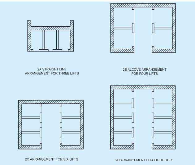
5.1.1 The guidelines laid down together with Fig. 2 will enable the preliminary scheme for the installation to be established. Figure 2 shows only some of the typical arrangements and variations are possible with respect to number of lifts and the layout of lifts especially when destination control system (DCS) is used instead of conventional group control system
Although the recommended outline for the various classes of lifts enable the general planning details to be determined by the architect/engineer, these should be finally settled at the earliest possible stage by detailed investigation with the purchaser's representative reaching agreement with the lift manufacturer (where necessary) before an order is finally placed. This will enable a check to be made and information to be exchanged on vital matters such as:
a) Number, capacity, speed and disposition of the
lifts necessary to give adequate lift service in the proposed building;
b) Provision of adequate access to the machine room;
c) Loads which the lift will impose on the building structure, and the holes to be left in the machine room floor and cut-outs for wall boxes for push-buttons and signals;
d) Necessity for and type of insulation to minimize the transmission of vibration and noise to other parts of the building;
e) Special requirements of local authorities and other requirements set out in the ‘planning permit’;
f) Need for the builder to maintain accuracy of building as to dimensions and in-plumb;
g) Periods of time required for preparation and approval of relevant drawings for manufacturing and the installation of the lift equipment;
h) Requirements for fixing guide brackets to the building structure;
j) Time at which electric power will be required before completion to allow for testing;
k) Requirements for electrical supply feeders, etc;
m) Requirements for scaffolding in the lift well and protection of the lift well prior to and during installation of equipment; and
n) Delivery and storage of equipment.
5.1.2 Information to be provided by Architect or Engineer
As a result of preliminary discussions, the drawings of the building should give the following particulars and finished sizes:
a) Number, type and size of lifts and position of lift well;
b) Particulars of lift well enclosure;
c) Size, position, number and type of landing doors;
d) Number of floors served by the lift;
e) Height between floor levels;
f) Number of entrances;
g) Total headroom;
h) Provision of access to machine room;
j) Provision of ventilation and, if possible, natural lighting of machine room;
k) Height of machine room;
m) Depth of lift pit;
n) Position of lift machine, above or below lift well;
20
FIG. 2 TYPICAL ARRANGEMENT OF LIFTS
p) Size and position of any trimmer joists or stanchions adjacent to the lift well at each floor;
q) Size and position or supporting steel work at roof levels;
r) Size and position of any footings or grillage foundations, if these are adjacent to the lift pit; and
s) In the case of passenger lifts whether the lift cage is required to carry household luggage, such as refrigerator, steel almirah, etc.
5.2 The lift lobby should be designed appropriately since this has bearing on the traffic handling especially when more number of lifts are involved. In a dual line arrangement (lifts opposite to each other) the lobby should be between 1.5 times and 2.5 times the depth of one car. Typically, the greater the number of lifts, the bigger the multiplier to be used. As an example, a quadruplex may use 1.5 to 2, where as an octoplex will need 2 to 2.5. For in-line (single line) arrangements, the lobby can be typically half of the above recommendations.
It is preferable that the lift lobby is not used as a thoroughfare. If unavoidable the lift corridor shall take into account space for people who are moving.
5.3 The architect/engineer should advise the lift manufacturer, if the Authority has any special requirements regarding lifts in buildings in the administrative area concerned.
5.4 The architect/engineer should inform the lift manufacturer of the dates when the erection of the lift may be commenced and is to be completed so that sufficient time is allowed for the manufacture and erection of the lift.
5.5 When submitting application for a building permit to the local Authority, the building plans shall include the details of lifts (number of lifts duly numbered, location, type, type of doors, passenger capacity and speed).
5.7General Arrangement Drawings (GAD)
The general arrangement drawings should be prepared
by the lift manufacturer. The lift manufacturer requires sufficient information for the preparation of working drawings and is usually obtained from architect's drawings supplemented by any information obtained from the site and by collaboration with the other contractors.
General arrangement drawings showing the layout of lifts duly numbered, details of builders work, for example, holes in walls for guide fixing, holes in machine room floor for ropes and conduits, recesses for landing sills, supports for lift machine and loads imposed on the building should be submitted by the lift manufacturer to the architect/engineer for written approval.
5.8Additional Requirements for Passenger, Goods and Service Lifts
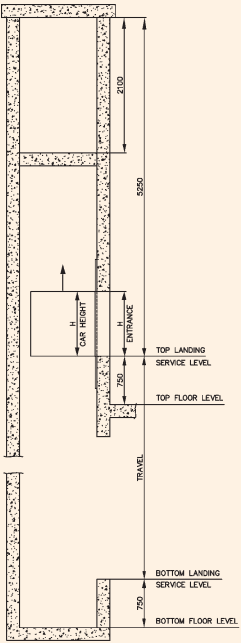
5.8.1 Bottom Car Clearance
When the car rests on its fully compressed buffer there shall be a vertical clearance of not less than 600 mm between the pit floor and the buffer striker plate or the lowest structural or mechanical part equipment or device installed. The clearance shall be available beneath the whole area of the platform except for,
a) guide shoes or rollers, safety jaw blocks, platform aprons, guards of other equipment located within 300 mm measured horizontally from the sides of the car platform; and
b) compensating sheaves.
Provided that in all the cases, including small cars, a minimum clearance of 600 mm is available over a horizontal area of 800 mm × 500 mm.
Provided also that in all the cases, when the car rests on its fully compressed buffers, there shall be a vertical clearance of not less than 50 mm between any part of the car and any obstruction of device mounted in the pit.
5.8.2 Top Car Clearance
The vertical clearance between the car cross-head and the nearest overhead obstruction within 500 mm measured horizontally to the nearest part of the crosshead when the car platform is level with the top landing, shall be not less than the sum of the following:
a) Bottom counterweight run-by.
b) Stroke of the counterweight buffer used.
c) One-half of the gravity stopping distance based on,
115 percent of the rated speed where oil buffers are used and no provision is made to prevent the jump of the car at counterweight buffer engagement; and
Governor tripping speed where spring buffers are used.
NOTE — The gravity stopping distance based on the gravity retardation from any initial velocity may be calculated according to the following formula
S = 5 1 V ²
where
S = free fall, in mm (gravity stopping distance), and
V = initial velocity, in m / s
d) 600 mm.
Where there is a projection below the ceiling of the well and the projection is more than 500 mm, measured horizontally from the centre line of the cross-head but over the roof of the car, a minimum vertical clearance not less than that calculated above shall also be available between the roof of the car and the projection.
Provided that the vertical clearance between any equipment mounted on top of the car and the nearest overhead obstruction shall be not less than the sum of the three items (a), (b) and (c) as calculated above plus 150 mm.
5.8.3 Bottom Run-by for Cars and Counterweights
The bottom run-by of cars and counterweights shall be not less than the following:
a) 150mm, where oil buffers are used.
b) Where spring-buffers are used;
150 mm for controls as in 2.1.11.4 to 2.1.11.8, and
Not less than the following for controls as in 2.1.11.1 to 2.1.11.3:
Rated Speedm/s
Run-bymm
Up to 0.125
75
0.125 to 0.25
150
0.25 to 0.50
225
0.50 to 1
300
5.8.4 Maximum Bottom Run-by
In no case shall the maximum bottom run-by exceed the following:
a) 600mm for cars; and
b) 900mm for counterweights.
5.8.5 Top Counterweight Clearances
The top counterweight clearance shall be not less than the sum of the following four items:
a) Bottom car run-by.
b) Stroke of the car buffer used.
c) 150 mm.
d) One-half the gravity stopping distance based on,
115 percent of the rated speed where oil buffers are used and no provision is made to prevent jump of the counterweight at car buffer engagement; and
governor tripping speed where spring buffers are used.
5.9Additional Requirements for Dumb Waiters
5.9.1 Top Car Clearance
The top car clearance shall be sufficient to avoid any protruding part fixed on the top of the car coming in direct contact with the ceiling or diverting sheave.
The clearance shall be calculated taking into account the following and shall not be less than the sum of the following four items:
a) Bottom counterweight run-by.
b) Stroke of the counterweight buffer used.
c) Dimensions of the portion of the diverting sheave hanging underneath the ceiling in the lift well.
d) 150 mm for compensating for gravity stopping distance and future repairs to the rope connections at counterweight and at the car or at the suspension points.
5.9.2 Bottom Car Clearance
The bottom car clearance shall be maintained in such a way that the counterweight shall not come in contact with the ceiling or any part hanging underneath the ceiling, when the car completely rests on fully compressed buffers, provided the buffers are spring type mounted on solid concrete or steel bed.
In case of wooden buffers the bottom car clearance shall be maintained in such a way that the total downward travel of the car from the service level of the immediate floor near the pit, shall not be more than the top counterweight clearance, when the wooden buffers are completely crushed.
5.9.3 Top Counterweight Clearance
The top clearance for the counterweight can be calculated taking into account the following and shall not be less than the sum of the following three items:
a) Car run-by.
b) Compression of the buffer spring or height of the wooden block used as buffer.
c) 150 mm to compensate for gravity stopping distance for counterweight and any future
repairs to rope connections at the counterweight at the car ends or at the suspension points.
5.9.4 Run-by for Cars and Counterweights
a) Minimum bottom run-by — The bottom run-by for cars and counterweights shall not be less than 150 mm.
b) Maximum bottom run-by — In no case shall the maximum bottom run-by exceed 300 mm.
5.10Planning for Dimensions
5.10.1 General
The dimensions of lift well have been chosen to accommodate the doors inside the well which is the normal practice. In special cases, the door may be accommodated in a recess in the front wall, for which prior consultation shall be made with the lift manufacturer.
5.10.2 Plan Dimensions
All plan dimensions of lift well given hereunder, are the minimum clear plumb sizes. The architect/engineer, in conjunction with the builder, shall ensure that adequate tolerances are included in the building design so that the specified minimum clear plumb dimensions are obtained in the finished work.
NOTE — The words ‘clear plumb dimensions’ should be noted particularly in case of high rise buildings.
Rough opening in concrete or brick walls to accommodate landing doors depend on design of architrave. It is advisable to provide sufficient allowances in rough opening width to allow for alignment errors of opening at various landings. When more than one lift is located in a common well, a minimum allowance of 150 mm for separator beams shall be made in the widths shown in Tables 1 to 4.
Where the governor operated counterweight safety is required under conditions stipulated in good practice [8-5A(5)], the tabular values should be revised in consultation with the lift manufacturer.
For outline dimensions of lifts having more than one car entrance, lift manufacturers shall be consulted.
5.10.3 Outline Dimensions
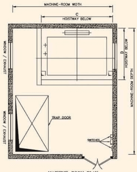
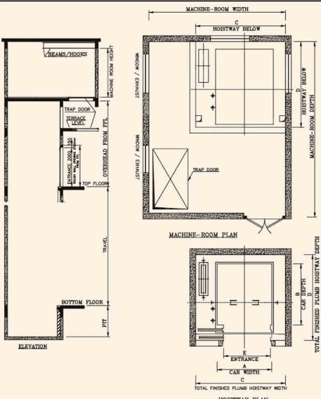
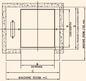
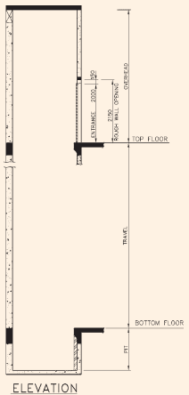
5.10.3.1 The outline dimensions of lift shaft, machine-room, pit depth, overhead and raw door opening size for lifts to which this Subsection applies are specified in Tables 12 to 23 as indicated below:
a) Machine room lifts:
Machine room lifts:
Recommended : Table 12
dimensions of passenger lifts and service lifts
Recommended : Table 13
dimensions of hospital bed/stretcher lifts
Recommended : Table 14
dimensions of goods lifts with machine room
Recommended : Table 15
dimensions of machine room height, overhead, pit depth for passenger, goods, stretcher/hospital lifts with machine room
Recommended : Table 16
dimensions of automobile lifts with machine room — Through type car
Recommended : Table 18
dimensions of passenger lifts MRL
Recommended : Table 19
dimensions of stretcher/hospital lifts MRL
Pit depth for passenger/ stretcher/hospital lifts MRL
Overhead height for passenger and stretcher/hospital lifts MRL
Recommended : Table 20
dimensions of goods lifts MRL
Recommended : Table 23
dimensions of automobile lifts MRL
5.10.3.2 Minimum floor to floor height
Minimum floor to floor height for landings on same side for horizontally sliding door is f+750 mm, where 'f' is clear entrance height, in mm.
6CIVIL and Electrical Requirements for Lifts
6.1 Civil Requirements
Lift well enclosures, lift pits, machine rooms and machine supports besides conforming to the essential requirements given below should form part of the building construction and comply with the lift manufacturer's drawings.
6.1.1 Requirements of Lift Well Enclosure
The requirements of lift well enclosures are as given hereunder:
a) Totally enclosed well — Lift wells shall be totally enclosed by imperforate walls, floor and ceiling, constructed for protection against all weather and of dust free surface material or should be painted to minimize dust circulation on to moving apparatus and from being pumped by the car movement in to machine room or on to landings and shall be 120 min fire-resistant.
The lift well may have openings for landing doors, inspection and emergency doors, vent openings for escape of gases and smoke in case of fire, ventilation openings, openings in the machine room floor for connecting lift components such as ropes, cables, etc.
b) Partially enclosed well — In case of partially enclosed lift wells used for applications for example, observation lifts in connection with galleries or atriums, etc, the well does not need to be totally enclosed, provided the height of the enclosure at places normally accessible to persons is sufficient to prevent such persons:
being endangered by moving parts of the lift; and
interfering with the safe operation of the lift by reaching lift equipment within the well either directly or with hand held objects.
The height of the enclosure shall be minimum 3.5 m at the landing door side. The height of enclosure at other sides shall be 2.5 m minimum when the horizontal distance between the moving parts of the lift and enclosure is 0.5 m minimum. The height of enclosure at other sides may be reduced to 1.1 m progressively if the horizontal distance between the moving parts of the lift and enclosure increases to 2 m. The enclosure shall be located within 150 mm of the edge of the floor. The enclosure shall be imperforate and made of non combustible material.
Supplied by Book Supply Bureau Under the License from BIS for LARSEN AND TOUBRO CONSTRUCTION - MANAPAKKAM, CHENNAI ON 17-03-2017 09:00:59 (123.63.24.35) valid upto31-12-2
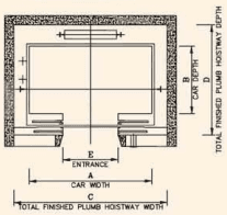
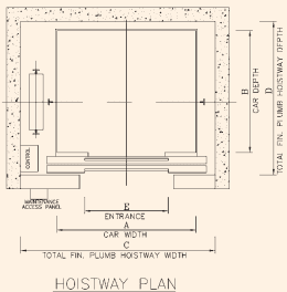
Table 12 Recommended Dimensions of Passenger Lifts and Service Lifts (Clause 5.10.3.1)
All dimensions in millimetres.
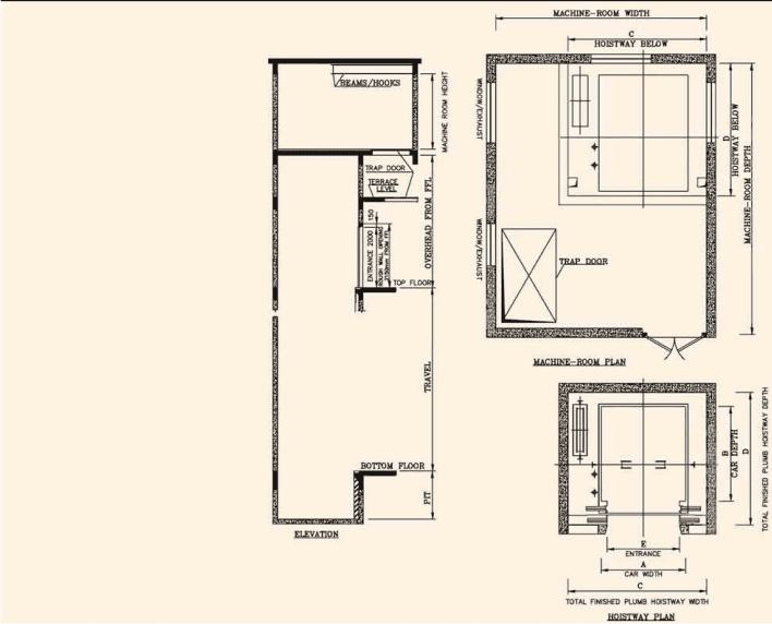
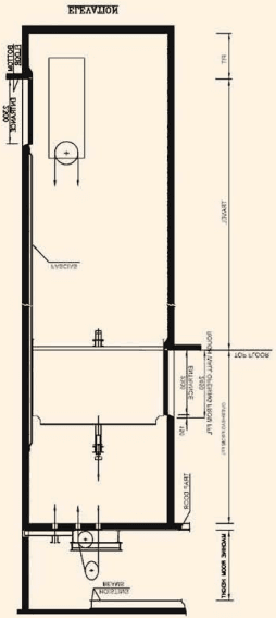
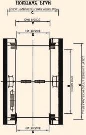
HOISTWAY PLAN
Book Supply Bureau Under the License from BIS for LARSEN AND TOUBRO CONSTRUCTION - MANAPAKKAM, CHENNAI ON 17-03-2017 09:00:59 (123.63.24,35) valid u
Table 12(Concluded)
Sl No.
No. of Passengers
Rated Load
Car Size
COPD Door
Passenger and Service Lifts with Machine Room: Shaft Sizes
Rated speed < 1 m/s Shaft Size
1.0 m/s ≤ Rated Speed ≤ 2.5 m/s Shaft Size
3.0 m/s ≤ Rated Speed ≤ 3.5 m/s Shaft Size
4.0 m/s ≤ Rated Speed ≤ 5.0 m/s Shaft Size
Rated Speed = 6.0 m/s Shaft Size
7.0 m/s ≤ Rated Speed ≤ 8.0 m/s Shaft Size
9.0 m/s ≤ Rated Speed ≤ 10.0 m/s Shaft Size
Width (4)
Depth (5)
Width (6)
Width (7)
Depth (8)
Width (9)
Depth (10)
Width (11)
Depth (12)
Width (13)
Depth (14)
Width (15)
Depth (16)
Width (17)
Depth (18)
Width (19)
Depth (20)
i)
4
272
1 100
700
800
1 900
1 300
1 900
1 300
ii)
6
408
1 100
1 000
800
1 900
1 700
1 900
1 700
iii)
8
544
1 300
1 100
800
1 900
1 900
1 900
1 900
iv)
10
680
1 300
1 350
800
1 900
2 150
1 900
2 150
v)
13
884
2 000
1 100
900
2 600
1 900
2 600
1 900
vi)
14
952
1 600
1 400
900
2 200
2 100
2 200
2 100
2 200
2 150
2 250
2 150
2 250
2 250
2 300
1 All dimensions given above for lifts having centre opening power operated doors (COPD) with counterweight at rear, are recommended dimensions primarily for architects and building planners. Any variations mutually agreed between the manufacturer and the purchaser are permitted. However, variation in,
a) car inside dimensions shall be within the minimum and maximum area limits specified in accordance with accepted standards [8-5A(6)].
b) entrance width on higher side is permitted.
c) entrance width on lower side is permitted up to 100 mm subject to minimum of 700 mm.
2 The minimum size of the lift car and all other requirements relating to accessibility, in all public buildings shall be in accordance with 13 of Part 3 'Development Control Rules and General Building Requirements' of the Code.
bok Supply Bureau Under the License from BIS for LARSEN AND TOUBRO CONSTRUCTION - MANAPAKKAM, CHENNAI ON 17-03-2017 09:00:59 (123.63.2435) valid u
NATIONAL BUILDING CODE OF INDIA 2016
Supplied by Book Supply Bureau Under the License from BIS for LARSEN AND TOUBRO CONSTRUCTION - MANAPAKKAM, CHENNAI ON 17-03-2017 09:00:59 (123.63.24.35) valid upto31-12-2
All dimensions in millimetres.
Table 13 Recommended Dimensions of Stretcher/Hospital Lifts (Clause 5.10.3.1)
HOISTWAY PLAN
Book Supply Bureau Under the License from BIS for LARSEN AND TOUBRO CONSTRUCTION - MANAPAKKAM, CHENNAI ON 17-03-2017 09:00:59 (123.63.24,35) valid u
Sl No.
No. of Passengers
Rated Load
Rounded off Rated Load
Car Size
2P TSPD Door
Hospital Bed / Stretcher Lifts with Machine Room: Shaft Sizes
Rated Speed ≤ 1 m/sShaft Size
0.6 m/s ≤ Rated Speed ≤ 2.5 m/sShaft Size
3.0 m/s ≤ Rated Speed ≤ 3.5 m/sShaft Size
4.0 m/s ≤ Rated Speed ≤ 5.0 m/sShaft Size
Rated Speed = 6.0 m/sShaft Size
7.0 m/s ≤ Rated Speed ≤ 8.0 m/sShaft Size
9.0 m/s ≤ Rated Speed ≤ 10.0 m/sShaft Size
(1)
(2)
kg (3)
kg (4)
Width (5)
Depth (6)
Width (7)
Depth (8)
Width (9)
Depth (10)
Width (11)
Depth (12)
Width (13)
Depth (14)
Width (15)
Depth (16)
Width (17)
Depth (18)
Width (19)
Depth (20)
Width (21)
i)
15
1 020
1 000
2 400
800
1 800
3 000
1 800
3 000
ii)
20
1 360
1 300
2 400
1 200
2 300
3 000
2 350
3 000
2 350
3 000
2 350
3 000
2 500
3 000
2 500
3 000
iii)
26
1 768
1 800
1 400
2 550
1 200
2 500
3 050
2 500
3 050
2 500
3 050
2 500
3 050
2 600
3 150
2 650
3 150
iv)
29
1 972
2 000
1 500
2 700
1 400
2 650
3 200
2 600
3 200
2 600
3 200
2 600
3 200
2 700
3 200
2 700
3 200
v)
36
2 448
2 500
1 800
2 700
1 400
2 800
3 150
2 900
3 200
Book Supply Bureau Under the License from BIS for LARSEN AND TOUBRO CONSTRUCTION - MANAPAKKAM, CHENNAI ON 17-03-2017 09:00:59 (123.63.24,35) valid u
Supplied by Book Supply Bureau Under the License from BIS for LARSEN AND TOUBRO CONSTRUCTION - MANAPAKKAM, CHENNAI ON 17-03-2017 09:00:59 (123.63.24.35) valid upto31-12-2018
Table 14 Recommended Dimensions of Goods Lifts with Machine Room (Clause 5.10.3.1)
PART 8 BUILDING SERVICES—SECTION 5 INSTALLATION OF LIFTS, ESCALATORS AND MOVING WALKS: 5A LIFTS
Table 14(Concluded)
Sl No.
Rated Load
Car Size
COPD Door
0.6 m/s ≤ Rated Speed ≤ 2.5 m/s
3.0 m/s ≤ Rated Speed ≤ 3.5 m/s
4.0 m/s ≤ Rated Speed ≤ 5.0 m/s
Rated Speed = 6.0 m/s
7.0 m/s ≤ Rated Speed ≤ 8.0 m/s
9.0 m/s ≤ Rated Speed ≤ 10.0 m/s
kg(1)
Width(3)
Depth(4)
Width(5)
Shaft Size
Shaft Size
Shaft Size
Shaft Size
Shaft Size
Shaft Size
Depth(6)
Width(7)
Depth(8)
Width(9)
Depth(10)
Width(11)
Depth(12)
Width(13)
Depth(14)
Width(15)
Depth(16)
Width(17)
i)
1 000
1 400
1 800
2P-tel-1200
2 300
2 350
ii)
1 500
1 700
2 000
4P-1500
2 750
2 550
iii)
2 000
1 700
2 500
4P-1500
2 800
3 050
2 800
3 050
2 900
3 050
3 000
3 050
3 000
3 050
3 000
3 050
iv)
2 500
2 000
2 500
4P-1700
3 000
3 050
3 000
3 050
3 100
3 050
3 200
3 050
3 200
3 050
3 200
3 050
v)
3 000
2 000
3 000
4P-1700
3 000
3 550
3 000
3 550
3 100
3 550
3 200
3 550
3 200
3 550
3 200
3 550
vi)
4 000
2 500
3 000
6P-2100
3 700
3 650
3 700
3 650
vii)
5 000
NOTE — All dimensions given above for lifts having centre opening power operated doors (COPD) with counterweight at side, are recommended dimensions primarily for architects and building planners. Any variations mutually agreed to between the manufacturer and the purchaser are permitted. However, the minimum rated load for the goods lift shall be based on a load of not less than 3.45 kN/m² of the net inside car area.
Book Supply Bureau Under the License from BIS for LARSEN AND TOUBRO CONSTRUCTION - MANAPAKKAM, CHENNAI ON 17-03-2017 09:00:59 (123.63.24,35) valid u
Table 15 Recommended Dimensions of Machine Room Height, Overhead, Pit Depth for Passenger, Goods, Stretcher/Hospital Lifts with Machine Room (Clause 5.10.3.1)
All dimensions in millimetres.
For speed up to 3.5 m/s
Sl No.
No. of Passengers
Rated Load
Dimensions of Pit Depth, Overhead Height (HR) and Machine Room Height (MR)
0.7 m/s
1.0 m/s
1.6 m/s
2 m/s
2.5 m/s
3 m/s
3.5 m/s
Pit Depth(4)
HR(5)
MR(6)
Pit Depth(7)
HR(8)
MR(9)
Pit Depth(10)
HR(11)
MR(12)
Pit Depth(13)
HR(14)
MR(15)
Pit Depth(16)
HR(17)
MR(18)
Pit Depth(19)
HR(20)
MR(21)
Pit Depth(22)
HR(23)
MR(24)
i)
4
272
1 350
CH + 1 900
2 500
1 500
CH + 1 950
2 500
1 600
CH + 2 400
2 500
2 200
CH + 2 800
2 500
ii)
6
408
1 350
CH + 1 900
2 500
1 500
CH + 1 950
2 500
1 600
CH + 2 400
2 500
2 200
CH + 2 800
2 500
iii)
8
544
1 350
CH + 1 900
2 500
1 500
CH + 1 950
2 500
1 600
CH + 2 400
2 500
2 200
CH + 2 800
2 500
iv)
10
680
1 350
CH + 1 900
2 500
1 500
CH + 1 950
2 500
1 600
CH + 2 400
2 500
2 200
CH + 2 800
2 500
v)
13
884
1 350
CH + 1 900
2 500
1 500
CH + 1 950
2 500
1 600
CH + 2 400
2 500
2 200
CH + 2 800
2 500
bok Supply Bureau Under the License from BIS for LARSEN AND TOUBRO CONSTRUCTION - MANAPAKKAM, CHENNAI ON 17-03-2017 09:00:59 (123.63.25) (2435) valid up
PART 8 BUILDING SERVICES MOVING WALKS: 5A LIFTS
-SECTION 5 INSTALLATION OF LIFTS, ESCALATORS AND
Table 15(Concluded)
For speed from 4 m/s to 10 m/s
Sl No.
No. of Passengers
Rated Load
Passenger, Goods, Stretcher/Hospital Lifts With Machine Room: Dimensions of Pit Depth, Overhead Height (HR) and Machine Room Height (MR)
4 m/s
5 m/s
6 m/s
7 m/s
8 m/s
9 m/s
10 m/s
kg
Pit Depth
HR
MR
Pit Depth
HR
MR
Pit Depth
HR
MR
Pit Depth
HR
MR
Pit Depth
HR
MR
Pit Depth
HR
MR
Pit Depth
HR
MR
(1)
(2)
(3)
(4)
(5)
(6)
(7)
(8)
(9)
(10)
(11)
(12)
(13)
(14)
(15)
(16)
(17)
(18)
(19)
(20)
(21)
(22)
(23)
(24)
i)
14
952
4 600
CH + 3 450
4 000
4 700
CH + 3 450
4 000
5 500
CH + 3 800
4 300
5 900
CH + 5 000
4 300
6 500
CH + 5 800
4 300
7 100
CH + 6 500
5 000
7 500
CH + 6 900
5 000
ii)
16
1 088/1 000
4 600
CH + 3 450
4 000
4 700
CH + 3 450
4 000
5 500
CH + 3 800
4 300
5 900
CH + 5 000
4 300
6 500
CH + 5 800
4 300
7 100
CH + 6 500
5 000
7 500
CH + 6 900
5 000
iii)
18
1 224
4 600
CH + 3 450
4 000
4 700
CH + 3 450
4 000
5 500
CH + 3 800
4 300
5 900
CH + 5 000
4 300
6 500
CH — Car clear inside height measured from car finished floor level to false ceiling.
1 Recommended dimensions for pit depth, overhead and machine-room for different lift speeds are given in the table above. These dimensions may differ in practice as per individual manufacturer's design depending upon load, speed and drive. However, the pit depth and overhead shall be such as to conform to the requirements of bottom clearance and top clearance in accordance with the accepted standards [8-5A(7)].
33
3 In case of lift speeds 3.5m / s and 4m / s with rear counterweight the pit depth requirement could be less by about 500 mm to 1000 mm.
Book Supply Bureau Under the License from BIS for LARSEN AND TOUBRO CONSTRUCTION - MANAPAKKAM, CHENNAI ON 17-03-2017 09:00:59 (123.63.235) valid up to 247
Table 16 Recommended Dimensions of Automobile Lifts with Machine Room — Through Type Car (Rated Speed = 0.6 m/s or 1.0 m/s)
(Clause 5.10.3.1)
PART 8 BUILDING SERVICES—SECTION 5 INSTALLATION OF LIFTS, ESCALATORS AND MOVING WALKS:5A LIETS
Table 16(Concluded)
Sl No.
Rated Load
Car Size
COPD Door
Shaft Size
Car Height
Overhead Height
Pit Depth
Machine Room Height
Width
Depth
Width
Width
Depth
CH
HR
PH
MR
(1)
kg(2)
(3)
(4)
(5)
(6)
(7)
(8)
(9)
(10)
(11)
i)
2 500
2 500
5 300
4P-2 400
4 000
6 100
1 800
4 000
ii)
3 000
2 700
5 400
4P-2 400
4 000
6 200
iii)
4 000
3 000
5 800
6P-3 000
4 300
6 700
2 400
5 200
iv)
5 000
3 000
6 000
6P-3 000
4 300
6 900
2 000
4 500
1 All dimensions given above for lifts having centre opening power operated doors (COPD) with counterweight at side, are recommended dimensions primarily for architects and building planners. Any variations mutually agreed to between the manufacturer and the purchaser are permitted. However, the minimum rated load for the automobile lift shall be based on a load of not less than 1.45kN/m² of the net inside car area.
2 Dimensions of machine room height, pit depth and overhead may differ in practice as per individual manufacturer's design depending upon load, speed and drive. However, the pit depth and overhead shall be such as to conform to the requirements of bottom clearance and top clearance in accordance with the accepted standards [8-5A(7)].
3 The lift car width should be selected such that in case of emergency while the automobile is in the car-lift the driver should be able to open the automobile door and come out of the automobile.
Book Supply Bureau Under the License from BIS for LARSEN AND TOUBRO CONSTRUCTION - MANAPAKKAM, CHENNAI ON 17-03-2017 09:00:59 (123.63.24,35) valid u
ELEVATION
Table 17 Recommended Dimensions of Dumbwaiter Lifts (Clause 5.10.3.1) All dimensions in millimetres.
HOISTWAY PLAN
Sl No.
Load
Car Inside
Lift Well
Entrance
kg
A
B
H
C
D
E
(1)
(2)
(3)
(4)
(5)
(6)
(7)
(8)
i)
100
700
700
800
1 200
900
700
ii)
150
800
800
900
1 300
1 000
800
iii)
200
900
900
1 000
1 400
1 100
900
iv)
250
1 000
1 000
1 200
1 500
1 200
1 000
NOTE — Entrance width ‘E’ is based on assumption of provision of vertical biparting doors (no car door is normally provided)
Table 18 Recommended Dimensions of Passenger Lifts MRL COPD (Clause 5.10.3.1) All dimensions in millimetres.
Sl No.
No. of Passengers
Rated Load
Car Size
2 P COPD Door
1.0 m/s ≤ Rated Speed ≤ 2.0 m/s
Rated Speed = 2.5 m/s
Rated Speed = 3.0 m/s
kg
Width (4)
Depth (5)
Shaft Size
Shaft Size
Shaft Size
Width (7)
Depth (8)
Width (9)
Depth (10)
Width (11)
Depth (12)
(1)
(2)
(3)
i)
4
272
900
850
700
1 600
1 550
ii)
6
408
1 000
1 100
800
2 000
1 700
iii)
8
544
1 300
1 100
800
2 150
1 800
iv)
10
680
1 350
1 300
800
2 150
1 900
v)
13
884
1 600
1 400
1 000
2 550
1 950
2 550
2 050
2 550
2 250
vi)
15
1 020
1 600
1 550
1 000
2 550
2 050
2 550
2 150
2 550
2 250
vii)
16
1 088
1 600
1 600
1 000
2 550
2 100
2 550
2 200
2 550
2 300
viii)
20
1 360
1 800
1 700
1 100
2 700
2 300
2 700
2 350
2 700
2 350
ix)
22
1 496
1 800
1 900
1 100
2 700
2 400
2 750
2 450
2 750
2 450
x)
26
1 768
1 900
2 000
1 100
2 800
2 450
2 850
2 450
Table 19 Recommended Dimensions of Stretcher/Hospital lifts MRL (2P Telescopic Door/4P COPD, Speed 1.0 m/s to 2.0 m/s)
(Clause 5.10.3.1)
Sl No.
Rated Load
Car Size
Door Size
Shaft Size
Persons(2)
kg(3)
Width(4)
Depth(5)
(6)
Width(7)
Depth(8)
i)
15
1020
1100
2400
900
2150
2950
ii)
20
1360
1300
2400
1200
2350
2950
iii)
23
1600
1400
2400
1300
2450
2950
iv)
29
2000
1500
2700
1300
2450
3250
NOTES1 All dimensions given above for lifts having 2 panel telescopic or 4 panel centre opening power operated doors (4P COPD) with counterweight at side, are recommended dimensions primarily for architects and building planners. Any variations mutually agreed to between the manufacturer and the purchaser are permitted. However, variation in,i) car inside dimensions shall be within the maximum area limits specified in accordance with accepted standards [8-5A(6)].ii) entrance width on higher side is permitted.iii) entrance width on lower side is permitted up to 100 mm subject to minimum of 700 mm.2 Car depth of 2100 mm may be considered in residential/commercial buildings where use of only ambulance stretcher is envisaged.The hoist-way depth maybe reduced accordingly.
Table 20 Pit Depth for Passenger/Stretcher/Hospital Lifts MRL (Clause 5.10.3.1)
All dimensions in millimetres.
Sl No.
No. of Passengers
Pit Depth for Speed
1 m/s(3)
1.6 m/s(4)
1.8 m/s(5)
2 m/s(6)
2.5 m/s(7)
3 m/s(8)
i)
4
1 600
1 800
2 000
2 200
ii)
6
1 600
1 800
2 000
2 200
iii)
8
1 600
1 800
2 000
2 200
iv)
10
1 600
1 800
2 000
2 200
v)
13
1 600
1 800
2 000
2 200
2 500
3 100
vi)
15
1 600
1 800
2 000
2 200
2 500
3 100
vii)
16
1 600
1 800
2 000
2 200
2 500
3 100
viii)
20
1 800
1 800
2 000
2 200
2 500
3 100
ix)
22
1 800
1 800
2 000
2 200
2 500
3 100
x)
26
1 800
1 800
2 000
2 200
2 500
3 100
xi)
29
1 800
1 800
2 000
2 200
2 500
NOTE — Recommended dimensions for pit depth for different lift speeds are given in the table. These dimensions may differ in practice as per individual manufacturer's design depending upon load, speed and drive. However, the pit depth shall be such as to conform to the requirements of bottom clearance and top clearance in accordance with the accepted standards [8-5A(7)] .
Table 21 Overhead Height for Passenger and Stretcher/Hospital Lifts MRL (Clause 5.10.3.1)
All dimensions in millimetres.
Sl No.
No. of Passengers
For Speed
1 m/s(3)
1.6 m/s ≤ Rated Speed ≤ 2 m/s(4)
2.5 m/s(5)
3 m/s(6)
i)
4
CH + 1900
CH + 2400
ii)
6
CH + 1900
CH + 2400
iii)
8
CH + 1900
CH + 2400
iv)
10
CH + 1900
CH + 2400
v)
13
CH + 1900
CH + 2400
CH + 2600
CH + 2800
vi)
15
CH + 1900
CH + 2400
CH + 2600
CH + 2800
vii)
16
CH + 1900
CH + 2400
CH + 2600
CH + 2800
viii)
20
CH + 1900
CH + 2400
CH + 2600
CH + 2800
ix)
22
CH + 1900
CH + 2400
CH + 2600
CH + 2800
x)
26
CH + 1900
CH + 2400
CH + 2600
CH + 2800
xi)
29
CH + 1900
CH + 2400
CH + 2600
NOTE — Recommended dimensions for overhead for different lift speeds are given in the table. These dimensions may differ in practice as per individual manufacturer's design depending upon load, speed and drive. However, the overhead shall be such as to conform to the requirements of bottom clearance and top clearance in accordance with the accepted standards [8-5A(7)] .
1 CH is the clear car height from car finished floor level to car roof (goods lifts will normally not have any false ceiling).
2 Normal range for CH is 2100mm to 2400mm.
3 Door height is less than or equal to the car height CH.
4 In case counterweight safety is applicable check for dimensions with lift manufacturer.
5 All dimensions given above for lifts having telescopic or centre opening power operated doors (COPD) with counterweight at side, are recommended dimensions primarily for architects and building planners. Any variations mutually agreed to between the manufacturer and the purchaser are permitted. However, the minimum rated load for the goods lift shall be based on a load of not less than 3.45kN / m² of the net inside car area.
6 Recommended dimensions for overhead and pit depth for different lift speeds are given in the table. These dimensions may differ in practice as per individual manufacturer's design depending upon load, speed and drive. However, the overhead and pit depth shall be such as to conform to the requirements of bottom clearance and top clearance in accordance with the accepted standards [8-5A(7)].
Table 23 Recommended Dimensions of Automobile Lifts MRL COPD (Speed 0.5 m/s to 1.0 m/s)
(Clause 5.10.3.1)
All dimensions in millimetres.
Sl No.
Rated Load kg
Car Size
6P COPD Door Size: Opposite Entrances
Shaft Size
Overhead Height
Pit Depth
Width
Depth
Width
Width
Depth
HR
PH
(1)
(2)
(3)
(4)
(5)
(6)
(7)
(8)
(9)
i)
3 000
2 500
5 500
2 200
3 800
6 450
4 850
2 500
ii)
4 000
3 000
6 000
2 700
4 300
6 950
4 850
2 500
NOTES
1 Car height normal range is 2 100 mm to 2 700 mm.
2 Overhead height shown is required for all values of car height CH shown above.
3 In case counterweight safety is applicable check for dimensions with lift manufacturer.
4 All dimensions given above for machine room less lifts with 6 panel centre opening power doors (6P COPD) used for automobiles are recommended dimensions for architects and building planners. Any variations mutually agreed to between the manufacturer and the purchaser are permitted. However, the minimum rated load for the automobile lift shall be based on a load of not less than 1.45kN/m² of the net inside car area.
5 Dimensions of pit depth and overhead may differ in practice as per individual manufacturer's design depending upon load, speed and drive. However, the pit depth and overhead shall be such as to conform to the requirements of bottom clearance and top clearance in accordance with the accepted standards [8 5A(7)].
6 The lift car width should be selected such that in case of emergency while the automobile is in the lift car the driver should be able to open the automobile door and come out of the automobile.
c) General requirements related to the lift well — The well shall be exclusively used for lifts. It shall not contain cables or devices, etc other than for the lift. Permanently installed adequate lighting shall be provided comprising sufficient number of lamps fixed throughout the lift well such that the illumination level 1 m above the car roof within its vertical projection at any position of the car in the well and 1 m above pit floor everywhere a person can stand, work and/or move between the working areas shall be at least 50 lux and at least 20 lux at remaining locations, even when all the doors are closed.
NOTE — Additional lamps may be fixed on the car top as a part of the well lighting system to achieve this.
Well lighting switch shall be located in the machine room close to the main switch and pit lighting switch in lift well close to lower landing door.
Should a lift entrance open out in to an area exposed to the weather, the entrance should be protected by a suitable canopy and the ground level sloped up to the lift entrance to prevent rain or drainage water entering the lift well through the clearances around the landing doors. Any push buttons exposed should be of weatherproof type.
The approach of the landing door on each floor shall be kept lighted during the whole time the lift is available for use at night, and during the day time if so required due to insufficient natural light.
When the distance between consecutive landing door sills exceeds 11 000 mm, intermediate emergency landing(s) with lift landing door(s) shall be provided such that the distance between any two consecutive landings is not more than 11 000 mm. Rescue through these landings is permissible in case of automatic rescue device operation.
No counter-weight shall be allowed to travel in any lift well, or part of any lift well other than that to which it belongs.
In the case of a lift well which is common to more than one lift and where the lift car or the counterweight of one lift is working in juxtaposition to the lift car or counterweight of another lift, such lift cars or counterweights shall be guarded carefully and adequately in order to protect persons working in the lift well or on the lift cars from accidental contact with such cars or counterweights in any part of their travel.
d) Construction of the lift well — The side walls of the lift well may be made of reinforced cement concrete at least 150 mm thick; or brick or similar fire resisting materials
f)
provided tie beams are made available for lift guide rail fixings at such heights as specified by the lift manufacturer, so as to provide satisfactory anchoring arrangement for fixing guide rails and other equipment to the lift well. The inner surface of the lift well and its enclosure facing any lift-car entrance shall, so far as practicable, be kept smooth and flush devoid of projections or recesses. Where any projections or tops of the recesses cannot be rendered flush, they shall be levelled on the underside to an angle not less than 60° from the horizontal, by means of metal plates, cement rendering or other fire resisting material.
Where a lift car levelling device is operative with the lift car door open, such interior surfaces shall always form a smooth and flush surface below each landing level for a depth to at least the depth of the car-levelling zone plus the distance through which the lift car may travel of its own momentum when the power is cut-off.
The distance between the lift well enclosure on the sides facing any lift-car entrance and the sill edge of the car shall not be more than 30 mm in the landing zone below the landing gate. If such distance is more than 30 mm in the lift well enclosure, the same shall be finished with suitable and smooth plaster work or fascia plates so as to make the surface thereof devoid of all projections and recesses. In case the enclosure wall on the sides facing the lift-car entrance is more than 130 mm from the sill edge of the lift-car platform, the lift-car door of such lift shall be provided with means to prevent it from being opened except when the lift-car is at the landing served by such car entrance.
Sufficient space shall be provided between the guides for the car and the side walls of the lift well enclosure to allow safe and easy access to the parts of the safety gears for their maintenance and repairs.
All landing openings shall be protected by gates or doors which shall extend to the full height and full width of the landing openings. These openings shall not be less than 2 000 mm in clear height and 700 mm clear in width when the gates or doors are fully opened. There shall not be any common wall between lift well and water tank.
e) Strength of the walls of the well — The structure of the well shall be able to support at least the loads which may be applied by the
machine, by the guide rails at the moment of safety gear operation, by eccentric load in the car, by the action of buffers, by the application of anti-rebound devices, by loading and unloading the car, etc.
The walls of the well shall withstand a force of 1 000 N, being evenly distributed over an area of 900 cm ² in round or square section and applied at right angles to the wall at any point on either face,
without permanent deformation greater than 1 mm; and
without elastic deformation greater than 15mm.
Glass panels, plane or formed shall be made of laminated glass. Such panels and their fixings shall withstand horizontal static force of 1 000 N applied on an area of 900 cm ² at any point, from either side, without permanent deformation.
Partition walls between lifts in a common lift well — In case of common lift well for multiple lifts, the partition wall(s) of the common lift well may be either be RCC or brick or steel or glass which may be provided with openings for escape of air displaced due to movement of lift in the adjacent well. For high speed lifts the partition between the lifts maybe of suitable wire grill / expanded metal of following specifications:
It shall be made of at least 2.2 mm thick steel wire or expanded metal.
A ball of 25 mm diameter shall not pass through the wire grill.
It shall be so fixed as not to deflect more than 15 mm when subjected to a force of 450 N applied horizontally at any point from either side.
6.1.2 Requirements of the Pit
Pit shall be soundly constructed and maintained in a dry (water proofed) and clean condition. Where necessary, provision shall be made for permanent drainage. The floor of the pit shall be able to support beneath each guide rail, force due to mass of guide rails plus the reaction due to safety gear operation. The floor of the pit shall be able to support beneath the car buffer supports, force in Newton, equal to 4 times the static load being imposed by the mass of fully loaded car:
g (P + Q)
where
P = mass of empty car and components supported by the car, that is part of travelling
cable, compensating rope/chain, if any, etc, in kg;
Q = rated load, in kg; and
g = acceleration due to gravity.
The floor of the pit shall be able to support beneath the counterweight buffer support, force in Newton, equal to 4 times the static load being imposed by the mass of the counterweight:
g (P + q. Q)
where
P = mass of empty car and components supported by the car, that is part of travelling cable, compensating rope/chain, if any, etc, in kg;
Q = rated load, in kg;
g = acceleration due to gravity; and
q = live load balancing factor (normally, q = 0.5).
The floor of the pit shall be able to support upward thrust of the tied down rope compensation device, if provided. If accessible spaces do exist below the well, the base of the pit shall be designed for an imposed load of at least 5000N / m² and the counterweight shall be equipped with safety gear. In addition, it is recommended to provide double slab for the lift pit.
NOTES
1 Lift wells should preferably not be situated above a space accessible to persons.
2 Enclosing projected area of the lift shaft under the pit in accessible spaces will not nullify above provisions.
There shall not be any common wall/slab between lift pit and any water reservoir.
The pit shall be accessible by an access door. A permanent ladder inside the well may be provided close to the last landing in-lieu of access door, if the pit depth does not exceed 2.5 m.
NOTE — In case of structural limitations for providing pit access door at pit floor level, alternative arrangement to access pit may be provided which shall allow access to pit with complete safety.
A physical means of protection shall be provided to prevent accidental contact with the counterweight.
The pit shall be equipped with a stop switch which is easily accessible from the lowest landing and the pit floor. If more than one switch is required, they shall be wired in series.
6.1.3 Requirements Associated with Machine Room and Pulley Room
Generally lifts have machine rooms immediately over the lift well, and this should be arranged, whenever
possible without restricting the overhead distance required for normal safety precautions. In case where machine room provision on top is a limitation, either machine room less lift or basement drive or side drive lift can be considered. The spaces and tolerances shall be in accordance with the following:
a) Requirements associated with machine room and pulley room (where lift machinery is placed in the machine room)
The lift machine, controller and all other apparatus and equipment of a lift installation, except such apparatus and equipment having functional location in the lift well or other positions, shall be placed in the machine room which shall be adequately lighted and rendered fire-resistant and weather-proof.
If parts of different lifts are present in one machine and/or pulley room each lift shall be identified with a number, letter or colour consistently used for all parts (machine, controller, over speed governor, switches, etc).
Machine room should be considered as plant space, and conditions provided to permit reliable operation of electrical switchgear and rotating machinery, and be conducive to good maintenance. The machine room shall be either air conditioned or adequately ventilated so as to maintain the ambient temperature therein between +5°C and +40°C. The machine room shall be such that the motors and equipment as well as electric cables etc are protected as far as possible from dust and humidity. Machine room should also be protected from all weather and if ventilation louvers are provided, they should be designed and located to prevent entry of rain water in the machine room.
The well, machinery spaces and pulley rooms shall not be used to provide ventilation of rooms other than those belonging to the lift.
Rescue instructions with required tools and tackles, if any, shall be made available in the machine room.
Machine room floor shall be provided with a trap door, if necessary. The size of the trap door shall be as per manufacturer's recommendation. Since the purpose of the trap door is to lift or lower the machinery, controller, etc, between machine room and the top landing, it may be necessary to provide similar trap door in the terrace slab as well depending on the design of the building.
The trap door when closed shall be able to support 2000N on an area of 0.20m × 0.20m
at any position. The trap door shall not open downwards. Hinges, if any, shall be of a type which cannot be unhooked. Trap doors shall be locked. When the trap door is in the open position, precautions shall be taken to prevent the fall of persons (for example, a guardrail) and prevent the trapdoor from closing such as to cause a crushing hazard (for example by counterbalance).
8.2Power and Control Systems
8.2.1 Features Associated with Power Systems
The features associated with power systems are listed below.
8.2.1.1 Industrial switchgear
Switchgear for controlling lift power systems is characterized by its high duty cycle and its high rupturing capacity. Switchgear shall be robust enough and shall be so designed as to withstand the high duty cycle and high rupturing capacity introduced during the operation of the lifts.
8.2.1.2 Levelling accuracy
The levelling tolerances in accordance with good practice [8-5A(7)] are those which can be reasonably expected between no load and full load in either direction. With the VVVF drives good leveling accuracy can be expected.
8.2.1.3 Corrective levelling
This should only be used, when it is impossible otherwise to achieve the required levelling tolerances or on long travel lifts to maintain the required levelling tolerances during loading and unloading.
FIG. 4 TYPICAL INSCRIPTION ON DOORS
FIG. 5 TYPICAL NOTICE ON TRAP DOORS
FIG. 6 TYPICAL NOTICE ON ACCESS DOORS AND EMERGENCY DOORS
54
8.2.1.4 Levelling with variable voltage
A variable voltage system is one using continuous regulation which minimizes speed differences due to load variation. Therefore, the actual levelling speed is of less importance than the general refinement of its regulation control. In fact no levelling speed as such may be identifiable.
8.2.1.5 Overload tests
A lift is designed to operate and transport the contract load, at the required duty cycle, and should not by intention or habitually be used to carry overloads. During test as a safeguard to cover variable supply and temperature conditions a lift is checked for the car to complete one round trip with contract load plus 10 percent at nominal supply voltage and nominal ambient temperature. There is also a static test with contract load plus 25 percent to check that the brake will sustain the car. It is unnecessary to specify and additional overload test or capacity and in fact it is detrimental to the normal running efficiency and safety of the lift to do so.
8.2.1.6 Occasional extra load
It is not good practice to request that a lift should be designed to carry an occasional extra load. It is tantamount to specifying an excessive overload test which is detrimental to the normal running efficiency and safety of the lift.
8.2.2 Description of Operation Systems
The following description relates to the associated operating systems.
8.2.2.1 Methods of control systems
The methods of control systems are as follows [see 8.2.2.2 (a)]:
a) Attendant and dual control, and
b) Automatic push button operation.
8.2.2.2 Types of control systems
The features of control systems shall be as described below:
a) Automatic push button operation — Automatic control is a method of operation by which a momentary pressure on a push button sets the car in motion and causes it to stop automatically at any required lift landing. This is the simplest control system and it is sometimes referred to as push button control. A car answers a landing or car call, whichever is actuated first by momentary pressure provided the lift is not in use. Momentary pressure of a car push button will send the car
to the designated floor. The car always responds to a car push button in preference to a landing push button. With this type of control, a red landing signal light or direction arrow indicates that the car is in use that is the lift is travelling. This type of control is recommended for single passenger lifts serving up to 4 floors and goods lifts.
For special purposes, the following two systems may be considered:
Dispatch from landings as an additional feature for a goods lift with manually operated doors. The call is registered by pressing the car push button and when the doors are closed the car will travel to the designated floor.
Automatic with attendant control as an additional feature on goods lifts with a key operated switch in the car to transfer the control from normal automatic to attendant operation. There is also a visual call indicator with buzzer in the car to indicate to the attendant the landing floors at which push buttons have been pressed when the car is under attendant control.
b) Collective control — Collective control is a generic term for those methods of automatic operation by which calls made by pressing push buttons in the car and at lift landings are registered and answered by the car stopping in floor sequence at each lift landing for which calls have been registered irrespective of the order in which the calls have been made, and until all calls have had attention. Collective control of any form is usually not suitable for goods lifts except where loading is not expected to fill the car and additional loads can be taken at other stops.
c) Single push button collective control — Single push button collective control has a single push button at each landing. It is not recommended, as the direction in which it is desired to travel cannot be registered by the intending passenger.
d) Down collective control — Down collective is a control system where landing calls are registered from a single push button, irrespective of the car being in motion or the landing door being open and calls are stored until answered. Any number of car calls can be registered and the car will stop in sequence in the down direction at each of the designated floors. The car will travel in the up direction to the highest call registered stopping only in
6.2Electrical Installation Requirements
The lift manufacturer should specify, on a schedule, particulars of full load current, starting current, maximum permissible voltage drop, size of switches
and other details to suit requirements. The main power cable and lighting cable shall be routed through respective lift shaft for every lift. It is important that the switches at the intake and in the machine room which are provided by the electrical contractor are of correct size. No form of 'NO VOLT' trip relay should be included anywhere in the power supply of the lift.
6.2.1 Main Switches
For each lift, a main switch capable of breaking the supply to the lift on all the live conductors shall be provided. This switch shall be capable of interrupting the highest current involved in normal conditions of use of the lift.
This switch shall not cut the circuits feeding the following:
a) Car lighting and ventilation
b) Socket outlet on the car roof;
c) Lighting of machinery spaces;
d) Socket outlet in the machinery and pulley spaces and in the pit;
e) Lighting of the lift well including pit;
f) Alarm device; and
g) Automatic rescue device.
The switch shall be located,
in the machine room, where it exists;
where no machine room exists, in the control cabinet; and
at the emergency and test panel, when control panel is mounted in the well.
If the emergency panel is separate from test panel, the switch shall be at emergency panel. If the main switch is not easily accessible from the controller cabinet, then the cabinet shall be provided with an isolating switch.
The main switches shall have stable open and closed positions, and shall be capable of being locked-off in the open position with the use of a padlock or equivalent, to ensure no inadvertent operation takes place.
For a single lift, this switch should be fixed adjacent to the machine room entrance in the machine room. In a machine room common to more than one lift, each main switch should be conveniently situated with respect to the lift it controls.
The supply to the car light should be from a separate circuit, and controlled by a switch in the machine room. For multiple lifts with a common machine room a separate supply should be provided for each car. The car lighting supply should be independent of the power supply mains
Any capacitors to correct the power factor shall be connected before the main switch of the power circuit.
6.2.2 Residual Current Device
Residual current device (RCD), if provided, right type and sensitivity shall be selected.
The RCD shall,
a) have 10 times the maximum leakage current (300 mA maximum) as tripping current and be suitable for frequency converters with a 3-phase supply.
b) be sensitive for sinusoidal currents up to 1 000 Hz, insensitive for currents more than 1 000 Hz.
NOTE — This kind of RCDs are generally classified as 'Type B'.
Three-phase power supply for the lift should never be protected with a 30 mA residual current device (RCD). The 30 mA RCD trips easily when the lift starts to drive and prevents the lift to run. If the construction-time power supply is for some reason protected with a 30 mA residual current device (RCD), suitably sized isolation transformer needs to be provided by the electrical contractor.
6.2.3 Supply Cables Wiring and Apparatus
The main power supply cables providing the electricity supply to a lift installation shall be flame retardant type PVC or XLPE insulated armoured cables. The cable should be terminated in the main switch. For each lift, one 415+6 Percent-10 Percent V, 3-phase, 4-wire, 50 Hz and one single phase 230+6 Percent-10 Percent V, 2-wire, 50 Hz supply shall be independently provided. Other than this, power circuit at 230+6 Percent-10 Percent V percent for power and lighting sockets in the lift machine room and the lift shaft shall be provided. This is to facilitate maintenance and other related works with lighting and socket outlets while the lift is switched off.
No cables which are not part of lift installation shall be run in the lift well. The lift cables shall be run in respective lift wells.
Fixed electrical wiring for circuit voltage up to 250V located in lift wells shall be one of the following:
a) PVC wires encased in rigid metal conduit or trunking.
b) PVC insulated PVC sheathed cables.
c) PVC wires in flexible metallic or plastic conduits not exceeding 1 500 mm in length for limit switches, interlocks, push buttons and similar devices.
46
Control cables on lift cars shall be run in rigid metallic conduit or trunking. Short runs of flexible conduits may be used, where they are securely fastened in place and not exposed to oil and grease. Short runs of flexible cord may be used as flexible connections between fixed wirings on the car and the switch on car door provided that chord is securely fastened in position and so located as not to be subjected to mechanical damage.
Wiring in machine room shall be run in rigid metallic trunking. The trunking in machine room floor shall be flush with the finished floor to avoid trip hazard. The following additional requirements may also be taken care of:
The lift sub-circuit from the meter room should be separate from other building services. Each lift should be capable of being isolated from the mains supply. This means of isolation should be lockable. The electric supply cables shall run in a route safe from fire, subsequently within the respective lift shafts to the machine room.
For banks of interconnected lifts, a separate sub-circuit is required for the common supervisory system, in order that any car may be shut down without isolating the supervisory control of the remainder lifts.
When the alarm system is connected to a transformer or trickle charger, the supply should be taken from the machine room lighting.
All electrical supply lines and apparatus in connection with the lift installation shall be so constructed and shall be so installed, protected, worked and maintained that there may be no danger to persons therefrom.
6.2.4 Earthing
There shall be separate exclusive earth pit for the lift or a group of lifts or the same shall be connected to equipotential bonding system. There shall be two separate and distinct earth conductors provided from the earth pit to the machine room as per good practice [8-5A(8)]. The cross-sectional area of copper earthing conductor shall be not smaller than half that of the largest current-carrying conductor subject to an upper limit of 65 mm².
In case of buildings having earthing through earth mats or earth grids, it is permissible to earth the lift equipment with separate conductors from these earth mats/grids. Separate earth pits shall not be a requirement in this case.
The terminal for the earthing of the frame of the motor, the winding machine, the frame of the control panel, and similar electric appliances which normally carry the main current shall be at least equivalent to a 10 mm diameter bolt, stud or screw.
The terminal for the earthing of the metallic cases and covers of door interlocks, door contacts, call and control buttons, stop buttons, car switches, limit switches, junction boxes and similar electrical fittings which normally carry only the control current shall be at least equivalent to 5 mm brass screw (such terminal being one specially provided for this purpose), and the earth conductor size shall be at least equivalent to 0.5 mm² copper.
The earth conductor shall be secured to earthing terminal in accordance with the recommendations made in good practice [8-5A(8)] and also in conformity with the latest provisions of The Indian Electricity Act, 2003 and the Rules framed thereunder from time to time.
The exposed metal parts of electrical apparatus installed on a lift car shall be sufficiently bonded and earthed.
Where screwed conduit screws into electric fittings carrying control current making the case and cover electrically continuous with the conduit, the earthing of the conduit may be considered to earth the fitting. Where flexible conduit is used for leading into a fitting, the fitting and such length of flexible conduit shall be effectively earthed.
8.3Capacity and Loading
The minimum rated load of a passenger lift car corresponding to the net inside car area shall bear the relationship given in Fig. 7, the net inside car area being evaluated as shown in Fig. 8. The net inside car areas for various passenger capacities with corresponding minimum rated loads have been given in Table 24.
NOTES
1 The graph shown in Fig. 7 is based on the following formula: W = 35.05 A² + 325.66 A
where
W = rated load, in kg; and
A = net inside area, in m².
2 For rated loads exceeding those covered by the graph, value may be evaluated from the formula given above.
3 To avoid the possibility of serious overloading of bed lifts, they shall be treated as passenger lifts.
4 The minimum rated load for goods lifts shall be based on a load of not less than 3.45kN / m² of the net inside car area.
5 The minimum rated load for automobile lifts shall be based on a load of not less than 1.45kN / m² of the net inside car area. 6 When the load in a goods lifts consists of pallets or similar single piece loads loaded by means of a power truck, it is necessary during loading and unloading to take into account the total load on the car platform the capacity of the brake, and the resistance to slipping of the ropes on the sheave of a traction machine. Similarly, guide rails, guide fixing, car frame and platform shall be designed to withstand the horizontal thrust imposed by power trucks, motor vehicles and the like.
7 For motor vehicle and other special purpose lifts for transportation of light weight and heavy volume loads, the lift car inside dimensions mutually agreed to between the manufacturer and the purchaser will be permitted with the provision of a device to prevent the lift from starting from a landing in case of overloading.
58
8 A load plate giving the rated load of the lift shall be filled in each lift car in a conspicuous position. For passenger lifts, the rated load shall be given in number of person and kg. For goods lifts, the rated load shall be given in kg or other convenient units and in persons. For the purpose of this clause, a person shall be regarded as weighing 68 kg.
Table 24Minimum-Maximum Net Car Areas for Various Rated Loads (Clause 8.3)
Sl No.
No. of Passengers
Minimum Rated Load kg (3)
Minimum Net Inside Car Area m² (4)
Maximum Net Inside Car Area m² (5)
(1)
(2)
i)
4
272
0.68
0.77
ii)
5
340
0.85
0.95
iii)
6
408
1.00
1.12
iv)
7
476
1.16
1.28
v)
8
544
1.31¹⁾
1.45
vi)
9
612
1.46
1.60
vii)
10
680
1.61
1.76
viii)
11
748
1.77
1.91
ix)
12
816
1.92
2.05
x)
13
884
2.06
2.20
xi)
14
952
2.23
2.34
xii)
15
1 020
2.35
2.47
xiii)
16
1 088
2.48
2.61
xiv)
17
1 156
2.62
2.74
xv)
18
1 224
2.75
2.87
xvi)
19
1 292
2.88
3.00
xvii)
20
1 360
3.01
3.13
xviii)
21
1 428
3.14
3.25
xix)
22
1 496
3.26
3.38
xx)
23
1 564
3.39
3.50
xxi)
24
1 632
3.51
3.61
xxii)
25
1 700
3.62
3.73
xxiii)
26
1 768
3.74
3.85
xxiv)
27
1 836
3.86
3.96
xxv)
28
1 904
3.97
4.07
xxvi)
29
1 972
4.08
4.18
Minimum net car inside area for fireman lift is 1.43m²
FIG. 7 MINIMUM RATED LOADS FOR PASSENGER LIFT CAR
8.4 Other Technical and Safety Requirements
8.4.1 Passenger lifts shall be provided with power operated doors which are imperforate.
8.4.2 Power operated car doors on automatically operated lifts shall be so designed that their closing and opening is not likely to injure a person. The power operated car door shall be provided with a sensitive device which shall automatically initiate reopening of the door in the event of a passenger being struck or is about to be struck by the door, while crossing the entrance during closing movement. The effect of the device may be neutralized,
a) during the last 58 mm of travel of door panel in case of side opening doors;
NET INSIDE CAR AREA = A × B
NET INSIDE CAR AREA = A × B
FIG. 8 NET INSIDE CAR AREA FOR PASSENGER LIFTS
b) when panels are within 58mm of each other in case of center opening doors; and
c) during emergency fire operation.
The force needed to prevent the door from closing shall not exceed 150N and this measurement shall not be made in the first third of the travel of the door. In order to achieve this it is desirable that all power operated doors have a full length (covering at least 1600mm of car door height from bottom) infrared or equivalent light curtain safety to retract the door in the event of coming across any obstacle during closing of the door.
8.4.3 Single speed and two speed drives which are poor in levelling accuracy and energy consumption shall not be used for new lifts in view of availability of latest technology energy efficient variable voltage variable frequency (VVVF) drive systems with improved levelling accuracy.
8.4.4 For passenger lifts with car call button control in car, an additional car operating panel with call buttons shall be provided for ease of access to call buttons when the car is wider than 1 600 mm and/or the rated capacity of the lift is 16 passengers and more. This additional car operating panel shall be suitably located in the lift car.
8.4.5 Battery operated Automatic Rescue Device (ARD) shall be provided on all lifts to take lifts to the nearest possible landing in case of power failure, which includes power failure of one or more phases. In case of lifts equipped with backup generator with AMF (Automatic Mains Failure) panel, the provision of ARD is optional. For all lifts with ARD, an audio and visual indicator shall be provided inside the lift car to alert the persons trapped inside that they are being rescued. Capacity of batteries shall be such that minimum three rescue operations can be performed without recharging. Emergency light and at least one fan inside the lift car shall be operational till the end of rescue operation. Levelling accuracy of ±40 mm or better shall be achieved in the ARD Operation. The ARD should operate only when all safety circuits are operational. The safety circuits shall be checked and verified continuously during the rescue operation.
8.4.6 Minimum one stretcher lift shall be provided in each building having height more than 30 m so as to take care of medical as well as other emergencies. This lift shall have minimum car entrance width of 800 mm and car depth of 2 100 mm.
8.4.7 Every passenger lift shall be provided with an overload device which will prevent the lift from starting in case the lift car is loaded to 110 percent of the rated capacity of the lift or more. The lift shall remain stationery with door open. Audio and visual warning device shall be provided to alert the passengers in case of overload.
9.2Lifts Used in Private Apartments/Houses/Villas (Home Lifts)
9.2.1 The home lift is designed especially for private home having up to 4 stops (maximum rise 12m), where the usage of the lift is restricted primarily to the residents of the private home. Unlike conventional lifts which allow virtually unlimited access to members of the general public, in case of home lifts non-residents shall have limited access.
9.2.2 The rated capacity of the home lift shall be minimum 208kg (3 persons) and maximum 272kg (4 persons) and lift car speed shall not exceed 0.4m / s.
9.2.3 The home lifts shall conform to good practice [8-5A(11)] apart from other relevant provisions of this Section.
9.2.4 Electric MRL type home lifts, shall in addition conform to the technical requirements specified in good practice [8-5A(10)].
9.2.5 Hydraulic type home lifts shall in addition conform to the technical requirements specified in good practice [8-5A(1)].
9.3 Hydraulic Lifts
9.3.1 The hydraulic lift is a special type of lift where the lift car is directly or indirectly driven by action of one or more hydraulic jacks.
9.3.2 The hydraulic lifts shall conform to good practice [8-5A(1)] apart from other relevant provisions of this Section.
9.3.3 These lifts should preferably be hole-less type of lifts.
9.4 Lifts Accessible for Persons with Disabilities
9.4.1 All lifts open to public shall adhere to the accessibility provisions in terms of size of the car, door width, control panel, flooring, finishes, handrails, communication systems and information, given in 13 of Part 3 ‘Development Control Rules and General Building Requirements’ of the Code.
9.4.2 Lifts for persons with disabilities shall conform to good practice [8-5A(12)] apart from other provisions of this Section.
8Minimum Technical and Safety Requirements
8.1 General Requirements
The following general requirements shall be adhered to:
a) Passenger and goods lifts shall comply with the safety requirements and/or protective measures of the following clauses. In addition the passenger and goods lifts shall be designed according to good practices [8-5A(2)].
b) All labels, notices, markings and operating instructions shall be permanently affixed, indelible, legible and readily understandable (if necessary aided by signs or symbols). See also 13 of Part 3 ‘Development Control Rules and General Building Requirements’ of the Code. They shall be of durable material, placed in a visible position, and written in the accepted language(s).
c) The minimum factor of safety for any part of the lift shall not be less than five. Higher factor of safety for various parts shall be applicable in accordance with accepted standards [8-5A(5)] and [8-5A(6)].
d) All passenger, goods, stretcher, automobile, dumbwaiter lifts shall have conformity with Lifts Acts and Rules in force, Indian Electricity
bok Supply Bureau Under the License from BIS for LARSEN AND TOUBRO CONSTRUCTION - MANAPAKKAM, CHENNAI ON 17-03-2017 09:00:59 (123.63,84.35) valid up
Act, 2003 and Rules, all relevant and applicable Indian Standards, applicable fire regulations, fire prevention act and rules in force.
e) Notices — The following notices shall be placed at respective places:
A notice (see Fig. 4) bearing the following (typical) minimum inscription shall be fixed to the outside of doors or trap-doors (excluding landing doors and doors of emergency and test panels) giving access to machine and pulley rooms.
In the case of trap-doors, a permanently visible notice (see Fig. 5) shall indicate necessary warning to those using the trap-door.
Outside of the well, near the access doors and emergency doors, if any, there shall be a notice stating as shown in Fig. 6.
A notice board with following instructions as applicable, and/or other applicable instructions shall be placed in conspicuous position in the lift car:
i) Maximum capacity of lift ____ kg/____ persons.
ii) Close the car and landing door/gate properly, on entering, or while leaving the lift car.
iii) Do not open the lift-car gate when the lift-car is moving. The gate should only be opened after the lift-car has stopped opposite a landing gate.
iv) In case of danger, press the alarm button, but do not try to open the car door. Wait inside, until the lift car is brought opposite a landing, and do not attempt to leave the lift car until the landing door is opened fully.
v) Children under 12 years of age shall not use the lift, unless accompanied by an adult.
The following is a typical list of Do's and Don'ts that should be displayed in the lift car, and in case of lifts open to public use, in an accessible format complying requirements of accessible information board/signage, given in 13 of Part 3 'Development Control Rules and General Building Requirements' of the Code:
Do's
Don'ts
a) Press call button lightlyb) Know your destination. Push lift call for direction you want to goc) Stand aside for exiting passengerd) Pay attention to floor indicatore) Push and hold the door open button, if door needs to be held openf) Wait for the next car, if the lift is fullg) Take the stairs, if there is a fireh) In, contact case of emergency, contact customer service cell for rescue operation
a) Do not overload the liftb) Do not press call button again and againc) Do not force-open the doors, it is dangerousd) Do not stand in between the doorse) Do not fiddle with the equipmentf) Do not step in until lift has stopped at landing and doors are fully openg) Do not crowd in the middle of carh) Do not lean against car panelsj) Do not panic in case of power failurek) Do not attempt to jump out, if the lift has stopped out of floor level
NOTE — No distracting notice/advertisement should be fixed in the lift car.
8.6Emergency Manual Rescue
The emergency manual rescue operation with brake release should only be carried out in an emergency and by authorized persons who have received necessary instructions, because it is dangerous for any other persons to attempt to do so.
Before attempting to move the car, it is imperative that any person in the car be warned of the intention to move the car and that they shall not attempt to leave the car until they are advised that it is safe to do so. Any failure to carry out this precaution may render the person concerned guilty of negligence should an accident occur.
Before attempting to hand wind the lift machine, it is vital that the supply is switched off at the main switch. It is usually necessary to have two persons in the machine room: one to operate the brake release and the other to carry out the hand winding. The exceptions are small lift machines where the hand winding can be easily controlled by one man and larger machines which need two men to operate the hand winding alone with an additional man to control the brake release. In case of gearless machines especially, the brake shall be released and applied at very short intervals (of the order of 0.5 s to 1 s) so as to avoid the lift car attaining dangerously high speed due to the lift car and create unbalance in the absence of the gear box with large reduction ratio.
If the car is stuck in the lift well and cannot be moved when an attempt is made to move it in a downward direction, then no attempt at hand winding should be made because the car safety gear may have set. Any further procedure should be carried out under the instruction of a qualified lift mechanic. Provided the car is free to be moved in the downward direction, then it should be hand wound to the nearest floor. There is a preference to move the car in down direction. However, this may not always be practical owing to the distance involved and the time taken to complete the movement. In addition the amount of
out of balance load on the counterweight side, due to the size of car and the small number of persons inside it, may make it necessary to wind the car upwards. In the case of high speed lifts the direction of hand winding will usually be governed by the effort required to move the car because of the absence of a large gear reduction ratio. It is essential that all detail operations be carried out according to the manufacturer's instructions for the lift concerned and these should be clearly stated and permanently displayed in the form of a notice in the machine room.
9.5Seismic Resistance in Lifts
When seismic protection of the passengers and equipment is a consideration, the safety requirements and protective measures given below may be adopted, the specified requirements being applicable when the units are subject to seismic conditions where the specified design acceleration (a d) ≥ 1 , m/s2 :
NOTE — The design acceleration is a function of ground acceleration, soil behaviour, importance factor, etc. Thus, the value of (ad) applicable to the building and to be considered for lift design/installation shall be provided by the building architect or structural designer to the lift manufacturer.
a) General — Such lifts shall comply with the relevant safety requirements and/or protective measures of this clause to protect them when the lifts are subject to seismic conditions.
b) Lift well — In order to prevent that suspension ropes, governor ropes, travelling cables, compensation ropes and chains swaying in the well getting entangled with fixed equipment, snag points created by brackets, sills, devices and other equipment mounted in the well shall be protected according to Table 25.
c) Machinery and pulley spaces — Where buildings are designed with expansion joints
Table 25 Protection of Snag Points[Clause 9.5(b)]
Sl No.
Height of the Well
Horizontal Distance of Snag Points
Protected Equipment
Measures
Construction Scope
(1)
(2)
(3)
(4)
(5)
(6)
i)
≤ 20 m
Not necessary due to very small shake (displacement) of buildings
ii)
>20 m and ≤ 60 m
<900 mm
Travelling cables
Install protection measure for example, a protection wire in the corner of the rail bracket or other snag points near the travelling cables
Required, if any portion of the loop is closer than 900 mm from a snag point
subdividing the structure into dynamically independent units, all the lift machinery including the landing entrances and the well of the lift shall be located on the same side of an expansion joint.
d) Car
Mass of the car for lift design calculations — For lift design calculations, the forces generated by the design acceleration ( ad ) shall be calculated taking into account the following:
i) For passenger lifts the mass of the car plus 40 percent of the rated load evenly distributed; and
ii) For goods passenger lifts the mass of the car plus 80 percent of the rated load evenly distributed.
Car retaining devices — The retaining devices shall be placed in such a way to distribute loads in a similar way as the guide shoes. The retaining devices shall either be integrated or mounted close to
the fixing of the guide shoes. When the car is center located between the guide rails the clearances d₁ , d₂ and d₃ (see Fig. 9A) between the retaining device and the guide rail shall not exceed 5 mm and the dimensions chosen shall not cause accidental tripping of the safety gear during an earthquake.
The depth of the retaining device (z₁) shall be limited to avoid collision with guide rail attachments or other fixed devices, but long enough to guarantee a minimum required overlapping length between retaining devices and the guide rail blade during an earthquake.
During an earthquake, the minimum required overlapping length between retaining devices and the guide rail blade shall be at least 5 mm (see Fig. 9B).
The car structure and retaining devices shall be sufficient to withstand the loads and forces imposed on them including forces generated by the design acceleration (ad), without permanent deformation.
9B MINIMUM REQUIRED OVERLAPPING LENGTH OF RETAINING DEVICE DURING EARTHQUAKE
Key
d₁, d₂ and d₃ clearances between the retaining device and the guide rail
x guide rail x-axis
y guide rail y-axis
z₁ depth of the retaining device
z₂ blade height
z₃ overlapping length of retaining device during earthquake (≥ 5 mm)
FIG. 9 RETAINING DEVICE
e) Counterweight — The counterweight shall be provided with upper and lower retaining devices able to hold the frame in between its guide rails. The retaining devices shall be placed in such a way to distribute loads in a similar way as the guide shoes. The retaining devices shall either be integrated or mounted close to the fixing of the guide shoes. The clearances d₁ , d₂ and d₃ (see Fig. 9A) between the retaining devices and the guide rails shall not exceed 5 mm. When a safety gear is present, the dimensions chosen for the clearances d₁ , d₂ and d₃ shall not cause accidental tripping of the safety gear. During an earthquake, the minimum required overlapping length between retaining devices and the guide rail blade side shall be not less than 5 mm (see Fig. 9B). The counterweight structure and retaining devices shall be sufficient to withstand the loads and forces imposed on them including forces generated by the design acceleration ( a ), without permanent deformation. The strength of the retaining devices and the counterweight frame frame shall be calculated taking into account the vertical mass distribution of its weight blocks. If the counterweight incorporates filler weights, necessary measures shall be taken to prevent their movement outside the frame considering the design acceleration value.
f) Suspension and compensation
Protection for traction sheaves, pulleys and sprockets — The devices for preventing the ropes from leaving the grooves of traction sheaves and pulleys shall include one retainer no more than 15° from the points where the ropes enter and leave the grooves and at least one intermediate retainer every 90° of the angle of wrap. The strength and stiffness of the retainers and their distance to the traction sheaves and pulleys compared to the diameter of the ropes shall be such that they are effective. The devices for preventing the chains from leaving the sprockets shall include one retainer at the points where the chains enter and leave the sprockets.
Compensation chains — Compensation chains or similar means shall be guided in the pit in order to limit them from swaying and reaching snag points.
g) Precaution against environmental damage — Hydraulic lifts shall be provided with a rupture valve. The rupture valve shall comply with the requirements of 12.2 of good practice [8-5A(1)]. The space in which the hydraulic power unit is situated and the pit shall be
designed in such a way that it is impervious, so that all the fluid contained in the machinery placed in these areas will be retained if it leaks out or escapes.
h) Guide rail system
General — The guide rails, their joints and attachments shall comply with the requirements of good practice [8-5A(5)], and they shall also withstand the loads and forces generated by the design acceleration ( ad ). Retaining devices shall be used as frame supporting points in the guide rail verification.
Permissible stresses and deflections during seismic event — With provision of retaining devices the requirements stated below shall be fulfilled. The safety factors for guide rails shall satisfy Table 26.
Table 26Safety Factors for Guide Rails [Clause 9.5 h(2)]
Sl No.
Elongation (A5)
Safety Factor
(1)
(2)
(3)
i)
A5≥12%
1.8
ii)
8%≤A5<12%
3.0
For guide rails, the permissible stresses as given in Table 27 shall be used.
The maximum permissible deflection of car or counterweight guide rail in y-direction (see Fig. 10) shall be such that the overlapping length between the blade of the guide rail and the retaining devices is not less than 5 mm (see Fig. 9B). The maximum permissible deflection of the car guide rail, counterweight guide rail in x-direction (see Fig. 10) shall also be applied in y-direction. The maximum permissible deflection includes guide rail, its fixing bracket and separation beam, if used. For T-profile guide rails the maximum permissible deflection (in millimetre) (see Fig. 9A) is:
δperm = z ₁ - 2 d ₃ - 5
but never more than 40 mm.
KEY:
Fx = force exerted to the guide rail by the guide shoes or by the retaining devices in the x-axis.
Fy = force exerted to the guide rail by the guide shoes or by the retaining devices in the y-axis.
k) Electric installations and appliances
Electric installations in the lift well — The fixing of landing switch devices or final limit switches, vanes or similar devices fixed in the shaft shall be designed and installed to withstand the loads and forces imposed on them including forces generated by the design acceleration ( ad ). In addition, the devices mentioned above shall be protected by guards against damage caused by ropes and cables swaying in the well.
Behaviour of the lift in case of failure of the mains power supply — In case of seismic events, in order to avoid people getting trapped in the car in case of failure of the normal power supply, the lift has to be able to move automatically, the car to the next landing in up or down direction.
At landing, the lift shall operate as described below:
i) Lift with automatic power operated doors, when parked at a landing, shall open the doors, remove the lift from normal operation and keep the door open.
ii) For a lift with manually operated doors, when the car arrives at the designated landing, its door(s) shall be unlocked and the lift removed from normal operation.
Where local regulations do not permit the doors to remain open, a means shall be provided to open the doors (even with the electrical power on) enabling the rescue service to check whether the car is present and persons are not trapped.
The behaviour of the lift in case of failure of the normal power supply shall not override any of the following:
a) The electric safety devices.
b) Inspection operation.
c) Emergency electrical operation {see 9.5 of good practice [8-5A(6)]}.
d) The fireman's lift switch {see 8.3.14 of see good practice [8-5A(7)]}.
Seismic detection system — A seismic detection system shall be provided for lifts manufactured with design acceleration a d ≥ 4 , m/s2. For lifts manufactured with a d < 4 , m/s2 the provision of seismic detection system is optional.
NOTE — The scope of supply for seismic detector and wiring from the detector to the lift control panel should be discussed between the building owner or his representative, and the lift manufacturer.
Where the seismic detection system is used exclusively to send information to the lift it may be placed in the pit of the lowest lift in the building. In case of expected interference with other vibration sources, alternative locations of the seismic detection system are allowed.
The seismic detection system shall comply with the following:
i) Detection of tri-axial acceleration — The seismic detection system shall be able to operate at all times when the lift is intended to be available to users.
ii) Seismic trigger level — It shall be less than or equal to 1.00 m/s² in any direction including vectors.
NOTE — ‘Vector’ relates to the resulting acceleration from combined reactions in x, y and z planes.
11Special Technical Requirements for Super High Rise Buildings
The provisions given hereunder describes the different physical phenomena that occur in super high rise buildings (>200 m high) and have an effect on vertical transportation solutions.
Although there are no major differences with regard to suspension and guidance systems between high-rise and low-rise lifts, there are other aspects to be considered such as system technology and passenger comfort levels. Control system artificial intelligence levels, safety requirements, load-bearing component ratings, rope weight, energy consumption, and thus cost increase exponentially with the height of the building.
11.1 Air Pressure Effect
In high rise buildings, air pressure is different on ground level and on top of the building. Practically, pressure change on the ear becomes uncomfortable for some persons when lift is landing faster than 10 m/s. The thresholds are lower for small children, elderly persons
and passengers having flu. Therefore, practically, lifts are offered as a standard solution up to 10 m/s maximum.
11.2 Piston Effect
If high speed lifts especially those having rated speed greater than or equal to 4 m/s, are housed in single shaft, the displaced air due to movement of the lift car tries to escape through the gaps between the lift car walls and the shaft walls in turbulent flow. This phenomenon known as piston effect causes the quality of ride in the lift car to deteriorate. Noise level in the lift car may increase along with vibrations which will be felt by the passengers. The air being displaced past the car generates whining and whistling noises inside the car. Buffeting when passing doors may be audible and passenger may feel uncomfortable. Both lift car doors and landing doors may whistle at high speeds.
Therefore, high speed lifts should preferably be housed in common shaft with ventilation holes in the common wall(s), if any. These holes allow the air displaced due to the movement of the lift car to escape in the adjoining hoist-way. Thus, the velocity of the escaping air which depends on the ratio of the lift car area to lift shaft area reduces which mitigates the piston effect ensuring good ride comfort for the passengers. The size of the vent and the pitch at which the vents need to be provided depend on lift car size in relation to lift shaft size, as well as the speed of the lift and the ride comfort expected.
In addition, high speed lifts especially those having rated speed more than 6 m/s may be provided cars with aerodynamically designed exteriors. This special construction of the car however increases the requirements of the overhead and pit for which lift manufacturer should be consulted. To reduce hammering sounds caused by the passage of the lift past the landing doors, shaft in front of the lift car door may be clad with facia plates of full shaft width between the landing door sill of the upper floor and door header of the lower floor door to create an even, flush surface. Lift cars also need to be specially constructed to absorb noise and thus reduce transmission of noise in the car.
It is advisable not to have common wall between the lift shafts. There should be shaft divider beams provided at every floor level and in between floors, if required, for the support of the guide rail brackets. Metallic wire mesh shall be provided for separation of shafts.
11.3 Stack Effect
Stack effect is defined as the vertical, natural air movement throughout a high rise building caused by the difference in temperatures between the inside air and the outside air. Positive stack effect is characterized
by a strong draft from the ground floor to the roof. Positive stack effect is more significant in cold climates because of the greater difference in temperature between the inside and the outside of the building. The colder the weather and the taller the building, the greater will be the stack effect. Negative stack effect can also occur in the reverse direction in hot climates, but is not as significant because the difference in temperature is not as great.
The magnitude of stack effect is a function of,
a) building height;
b) air tightness of exterior walls;
c) air leakage between floors; and
d) difference in temperature between inside air and outside air.
The stack effect has following effects:
Differential pressure on the lift landing doors — The stack effect generates differential pressure on the landing doors. In case of buildings with airtight separation of each story the differential pressure on a particular landing door from inside and outside of the lift shaft is small however the pressure on the door of the first landing and that on the last landing varies a lot.
In case of buildings with no air partitions the converse is true. The differential pressure on a particular landing is significant and is the maximum at the top most and bottom most landings which are farthest from the neutral pressure level. At the neutral pressure level, which occurs somewhere in the mid of the building height, the differential pressure on the landing door from inside and outside of the lift shaft is nil.
The differential pressure on the landing door may cause difficulty in the operation of the door.
Smoke movement — The stack effect influences the smoke movement. In case of positive stack effect the air moves out from core of the building towards the exterior of the building above the neutral pressure level and it moves in from the exterior of the building to the core of the building below the neutral pressure level. In case of negative stack effect, reverse phenomenon occurs.
This air movement naturally affects the smoke movement in case of fire and has to be taken into account.
Since stairwells, lift shafts and lifts tend to contribute to the stack effect it is essential that all lift lobbies are well sealed and lifts parked
with door closed to minimize stack effect. Especially in case of fire the stack effect needs to be controlled to prevent the spread of smoke in the building. On the other hand, the stack effect may be beneficially used to quickly drive smoke out of the building in case of fire.
11.4 Building Sway
The wind induced sway of the building may cause the lift suspension and/or compensation ropes and lift car travelling cables to sway. Buildings have natural frequencies of oscillations. Similarly lift ropes also have natural frequencies of oscillations which depend on the position of the car in the hoist-way amongst other parameters. When natural frequencies of the ropes and the building match, a large amount of energy is transferred to the ropes and they start swaying violently. This results into reduced ride comfort for the passengers in the lift and increases possibility of ropes getting stuck to snag points in the shaft and damaging shaft equipment. In general, the rope and travelling cable resonance phenomenon should be taken into account in the lift design for over 200 m in height buildings and slender buildings over 150 m in height, for example, TV towers. It is a fact that the resonance cannot be completely avoided in high rise buildings, hence the need for the solutions to cope with the phenomenon. If resonance is not taken into account in the lift design, it could increase the lift out-of-service time and decrease lift ride comfort.
The main purpose of the sway management is to improve lift safety and service time by reducing rope sway by optimizing compensations ropes tension, providing shaft protection equipment to prevent ropes from entangling and damaging the lift equipment. A sway detector may be used to control the lift operations. The output signals from the sway detector are used to reduce the speed of the lifts or park them at a safe floor.
In order that the sway analysis is done, the building designer should be in touch with the lift designer since early design stage of the building and share information on the building natural frequencies, maximum amplitude of building displacement with probability of occurrence, etc. The lift designer would then be in a position to calculate the rope/cable sway and decide on the preventive measures to be taken in the lift design.
11.5 Ride Comfort
A robust car guidance system with meticulously aligned guide rails is essential for reducing vibrations to an acceptable comfort level. Guide rails shall be rated for heavy-duty usage. Irregularity in the guidance system causes an unpleasant and uncomfortable transverse vibration within the car at high speeds. High-quality roller guidance system is required for smooth ride. In
addition, the lift guidance system shall be able to withstand the effects of the building settling and the response of the building's structure to thermal and climatic changes.
11.6 Jump Lifts
In super high rise buildings there may be a need to start lift erection before the machine room is finished in order to compress total time required to complete the building. The self-climbing lift technique may be used to build the lift as the building construction progresses. Jump lift uses a temporary machine room that is moved upward as construction progresses. Typically, when the building construction reaches 7th floor, the jump lift may start operating and start serving lower floors. Exterior hoists can be removed sooner, enabling the façade to be enclosed. This means that lower floors are ready for finishing much earlier and the entire building can be completed sooner. Since all transportation takes place in a dry, windproof shaft, construction can continue safely and unhindered, even in bad weather. The change-over to final lift is very quickly done.
9.8Lift Interface with Building Management System (BMS)
Where required, a means to interface, monitor and control be provided by lift manufacturer, which should become the part of building management system. The following information and controls, but not limited to those, may be provided either through potential free contacts or building automation (BA) interface device
suitable for providing necessary lift information over other accepted communication protocols. With potential free contacts only lift monitoring is possible. It shall not be possible to control the lift.
a) Monitoring signals
Floor position of the lift for each lift.
Direction of travel for each lift.
Load condition of each lift specially indicating overload status.
Lift door status of each lift, whether open or closed.
Lift modes such as attendant, automatic, independent operation, emergency fire service, seismic mode, emergency medical service and inspection mode for each lift.
b) Control signals
Bring the lift down to lobby floor in case of emergency or VIP movement.
Park and shutdown lifts based on building and traffic requirements, so as to save power.
Force the lift into emergency fire service, seismic mode or emergency medical service, etc through command from BA system based on respective sensor's such as smoke detectors, seismic sensor, etc, input to BMS.
c) Reports — Software tools may be developed to report out performance of each lift such as average response time, number starts per hour, average lift uptime, round trip time, etc. Flexibility to provide additional reports based on building requirements.
The above mentioned requirement for potential free contacts, other standard protocols, etc, may be optional, if the full-fledged lift management system software is provided by lift manufacturer for monitoring and control of lifts in the building. This software may be custom built providing above mentioned requirements. The wiring between lift machine room to Building Management Systems shall be planned and carried out by the builder along with other wiring in the building.
12Lift Enquiry or Invitation to Tender
12.1 General
A period of two to four weeks is normally sufficient for return of tenders. This should be extended, if large numbers of lifts or special requirements are involved.
The enquiry documents should be kept to the essential minimum, and should be strictly confined to material relevant to the lifts works and to the particular project concerned.
When enquiring for and ordering lifts, the particulars given below should be furnished:
Type of lift (passenger, goods, service or dumb waiter);
Number of lifts required;
Capacity/Load of lift (s): number of persons (in kg);
Rated speed (m/s);
Travel (in m) and building height;
Floors served (no. of regular openings, emergency openings, blocked openings);
Method of control (simplex or group control);
Position of machine room (if machine roomless, machine below, hydraulic);
Machine room height;
Clear overhead/Clear top clearance;
Pit depth;
Sizes of hoistway (width x depth), in mm;
Position of counterweight;
Car size (width x depth), in mm;
Construction, design and finish of car bodywork;
Car entrances:
i) Number of entrances,
ii) Size (width × height), in mm
iii) Type of door (center opening, telescopic, 4 panel, vertical bi-parting), and
iv) Whether through opening.
Car light;
Call indicator;
Position indicator in car;
Lift landing entrances:
i) Number of entrances,
ii) Size (width × height), in mm
iii) Type of door or gates or shutters (for goods lifts) (centre opening, telescopic, 4 panel, vertical bi-parting), and
iv) Whether through opening.
Electric supply:
i) Power in volts a.c.,
ii) Phase, and
iii) Cycles (wire system).
Whether neutral wire available for control circuit;
Temporary guarding of hoist-way and car cabin;
Lighting volts a.c./d.c.;
Are premises subject to Lifts Act and Rules;
Disable friendly requirements [such as voice announcement of floor levels, accessible control panel (good contrast with the background wall, Braille, raised letter and font), railing on three sides, two way accessible communication system];
Earthquake protection requirements; and
Additional items.
12.2 Additional Items
The enquiry should state any additional items required beyond those specified in good practice, such as interface requirements, dismantling of existing lifts, fireman's control, seismic design consideration, sway/deflection requirements, gravity distortion, etc.
12.3 Finishes
Finishes should be specified at the enquiry stage or provisional sums should be included for them. Finishes to be considered may include interior car finish, false ceiling design, false ceiling lighting, flooring material
and weight, blower, ventilation details, car wall cladding details (weight to be considered), multimedia display details (like screen type, size, location, etc), door cladding details, transom details (flushed with the wall, material type, etc). See also 13 of Part 3 'Development Control Rules and General Building Requirements' of the Code.
12.4 Inclusions and Exclusions
A number of peripheral items are associated with lifts installation, of which some should always be provided by the builder and some are best included by the manufacturer. The requirements vary to some extent with the type of installation.
It is important that the limits of responsibility are clearly understood, and the enquiry documents should be specific in this respect.
The lifts manufacturer should include such items mentioned in 12.1.
The lifts manufacturer should exclude the supply and fixing of the items or as per the contract conditions as follows:
a) Builder's work such as forming lift well, pit and machine room, and building wall inserts.
b) Machine room floor including any reinforcement necessary for load bearing.
c) Hoisting hook/lifting beam fixing, where necessary.
d) Any necessary tanking, lining or reinforcement of the pit.
e) Diving beams for multiple wells and inter well pit screen (or as per the contract).
f) Trap door.
g) Intermediate beams for bracket fixing.
h) Door cladding (or as per the contract).
j) Cutting away and making good.
k) Working lights/permanent electricity supplies.
m) Site painting of steel work other than lift material (if any).
For more detailed discussion of the requirements for site preparation and work by other trades, reference should be made to good practice [8-5A(7)] and to other relevant clauses of this Section.
Facilities for the use of the main contractor's crane should be provided to assist in installing heavy equipment in addition to other unloading facilities on site in the course of erection.
The main contractor should be instructed to include these facilities in his own quantities.
Where the lift manufacturer agrees to use mobile platforms in place of lift well scaffolding, the general contractor should provide 400/440 V 3-phase and 200/
220 V single-phase supply in the lift shaft to operate such equipment, the supply to terminate at the position in the lift well required by the lift manufacturer.
These mobile platforms are limited in use for erection personnel and the transportation of light equipment only, but use of crane will also be necessary to assist in the installation of the heavy machinery and also in the initial installation of the mobile platform equipment.
12.5 Site Programme
The enquiry should indicate as accurately as possible the contract programme as it affects the manufacturer, in particular the target date for completion, construction schedule, site preparedness, the availability of crane for hoisting, coordination details (with other contractors like BMS interfacing, CCTV interfacing, etc).
14Coordination of Site Work
14.1 Preparatory Work on Site
In accordance with the general arrangement drawing for the lift, the representative of the lift company would brief the building owner or his nominated representative about the preparatory work that is required to be carried out before commencement of the lift installation.
The building owner will ensure that the preparatory work is done in accordance to the general arrangement of lift and also the state Lift Rules are followed for the construction of the lift shaft as well as machine room. Once the preparatory work is completed, the building owner or his nominated representative, will ask the lift company to cross check and see that everything is in order.
The representative of lift manufacturer shall check the lift shaft and bring the shortfalls, if any, to the notice of the building owner till the preparatory work is completed in compliance with the requirement of lift supplier. The following works shall be completed by the building owner before commencement of lift erection.
a) Lift well pit floor and side wall of the lift shaft may be plastered and water proofed. Pit shall be free from any water leakage/seepage and debris. Building owner shall ensure the construction of the pit depth in accordance with the speed of the lift as specified by the manufacturer in the general arrangement drawing.
b) In general the thickness of lift walls should be minimum 230 mm in brick or 150 mm in RCC. However, the lift shaft walls shall be constructed in consultation with structural engineers or consultant to verify the suitability based on lift load/reactions.
c) In case of brick walls it would be recommended to have concrete block at locations where the guide rail brackets are to be installed. Similarly in case of structural shaft suitable ISMC/ISMB should be provided by the builder to fix guide rail brackets at all bracket fixing levels. The lift manufacturer
will provide a drawing indicating the locations of brackets in the lift shaft.
d) Similarly for fixing the landing entrances, the builder has to provide RCC lintels/RCC beams for fixing landing door header and sill. In case of structural shaft suitable metallic channels have to be provided in the entrance area at lintel and floor level.
e) All the structural shafts have to be completely covered and finished in accordance to the local codes before the start of installation.
f) Suitable cut-outs near the entrance area as indicated in the lift general arrangement drawing have to be provided for fixing human interface system like landing operating panel, floor indicator, hall gong and lantern, emergency alarm, fireman switch and other devices like ‘THIS CAR NEXT’, group indicators, etc.
g) The building contractor shall provide load hooks/beams in machine room for machine room lift, one directly above the lift shaft and other directly on top of the trap door as specified in the lift general arrangement drawing. The same shall be provided in the slab in the overhead area for machine room less lifts, as specified by the lift manufacturer in their general arrangement drawing. The position of load hooks/beams provided by the building contractor shall be as specified by the lift manufacturer.
h) Machine room door shall be opening outside. It shall be minimum 1 m wide and 2 m in clear height with a platform outside.
j) Caution notice of 440 V and restricted entry shall be marked on the machine room door.
k) Fire extinguisher shall be provided by building contractor to prevent fire accidents.
m) The machine room shall be air-conditioned or adequately ventilated so as to maintain the ambient temperature between +5°C and +40°C.
n) The lift shaft in masonry shall be fully plastered. The shaft shall be given two coats of white-wash.
p) Scaffolding (bamboo/steel) shall be erected as required by the lift manufacturer with necessary safety measures. Adequate barricading needs to be provided on all the lift entrance opening to avoid mishap.
q) The building contractor shall provide proper illumination in the lift shaft, lift lobby, staircase and machine room.
14.2 Delivery of Material
The delivery of the material shall be made based on mutual agreement of the lift manufacturer and the building contractor. It is strongly recommended that the material should be delivered at site only when a suitable storage area is provided by the building contractor.
The scope of unloading and stacking materials shall be as per mutually agreed terms between the lift manufacturer and the building contractor. While unloading and shifting of materials due care shall be taken by both the parties to ensure safe unloading and shifting of materials.
Suitable equipment like hydra, fork lift, crane and trolleys shall be used for unloading and shifting of lift materials. Building contractor shall ensure safe passage for vehicles carrying materials, up to the storage area.
14.3 Storage
In order to enable efficient material distribution it is important that the material shall be unloaded from the delivery truck within a distance of 50 m of the storage/unit location and have proper access from unloading area to storage area. The building contractor shall provide the storage area near the installation site, that is within 20 m distance from the installation site. The minimum storage space per lift shall be 35 m² per lift.
The storage room should be dry, well lit, weather protected and should have locking arrangement and provision of a 16 A power point is recommended. The storage area provided by the building owner should have PCC flooring. The storage room shall be kept ready before arrival of material at site and will remain in possession of installation engineer till the erection of lift is completed and handed over to the owner.
The material shall be stacked in sequential manner, in accordance with the planned activities. The storage area should be provided at a suitable location near the vicinity of the lift shaft preferably above the ground floor level and should remain in possession of the lift supplier till the installation and commissioning work is completed. It is strongly recommended that the location of the store is not changed to avoid material damages.
14.4 Site Meetings
For the successful progress of the work, full cooperation among all agencies is essential. In large sites, regular meetings of such agencies are beneficial for coordination of work efficiently. Programme for the constructional work in that part of the building
containing the lift should be made in consultation among all parties concerned.
14.5 Service of Other Trades
The lift erector will require the services of architect, civil, and electrical contractors, and other agencies as the work proceeds, and it is essential that the lift erector should give due notice to the building contractor of the demands to be made on other trades, so that he can plan accordingly. Mutually agreed, periodic meeting to review work progress with agencies concerned would ensure better coordination and efficiency.
14.6 Scaffolding, Fencing, Wherever Provided
Scaffolds and stationary work platforms shall be erected in accordance with adequate safety under the supervision of a competent person. When used, wooden or synthetic planks shall be scaffold-grade or approved by a qualified person for scaffold and stationary work platform use, and the same shall be capable of withstanding 4 times the working load.
The assembly and disassembly of scaffolds and stationary work platforms shall be done using a safety harness and lifeline as required. All temporary lighting shall be so installed so as not to make any contact with the metal frames of the scaffold. Also the scaffolding shall be double earthed. Prior to carrying out any lift installation work, fencing and warning notices should be provided at all landings indicating that there are men at work.
14.7 System Building Sites
If the building programme allows insufficient time for lift erection in conventional fashion after the well is completely built special procedures are needed. This applies particularly to industrial and multi-storeyed buildings. The building contractor should provide a suitable portable cover to the completed portion of the lift well in order to protect the lift erectors working below against the weather and falling objects.
When the top of the well has been reached it is normal to cap it immediately with a precast load bearing floor slab on to which is lowered the pre-assembled machine room equipment. It then remains for the building contractor to complete and weatherproof the machine room as swiftly as possible. On all such projects the close cooperation between the building contractor and the lift manufacturer is essential.
14.8 Connecting to Power Supply
The lift manufacturer should give prior intimation to the building contractor of the date the power supply to the lift is required, so that suitable arrangements for connection can be made.
13Acceptance of Tender and Subsequent Procedure
13.1 General
The procedure indicated below particularly relates to the most usual case, where the lift manufacturer is the sub-contractor.
13.2 Order
The building owner places an order with the selected contractor for supply and installation of lifts. If alternative schemes have been offered, the order should clearly indicate which has been accepted.
13.3 Programme
The contractor shall submit a detailed programme after acceptance of the order showing his intended method, stages of the works, together with the period of time that has been estimated for each and every stage of progress.
The programme shall cover each lift separately, including dates, such as:
a) Date of order of equipment and materials;
b) Date of commencement and completion of every stage of the works in line with the building construction programme;
c) Date of expected completion of builder's work requirements;
d) Date of delivery of equipment and materials to site; and
e) Date of requirement of temporary and permanent electricity supply, and date of completion, commissioning and testing.
The period between order and delivery of material falls into two stages: first the finalizing of details and secondly the actual production of the equipment which
72
depends on the first stage. Within the first stage, other dates may need to be considered, such as:
All relevant building information available.
Submission of lift manufacturer's drawings.
Approval of drawings.
Final selection of finishes.
13.4 Drawings to be Submitted after Placing of Order
The lift manufacturer shall prepare layout drawings based on the civil/structure drawings, order requirements and submit to building owner within mutually agreed time frame. The same shall be briefed to building owner.
The drawings shall indicate clearly the position and sizes of all holes and cuttings, the loads on beams and structures, and all other requirements in relation to ‘Lift Installation’ namely:
a) Lift machine room and associated equipment, including sub-floor where appropriate.
b) All structural openings, such as landing entrances (including structural dimensions), ventilation openings, etc.
c) All bases, plinths, channels, holes, grouting-in of fixings, etc.
d) Lifting beams or other facilities for supporting lifting tackle in the machine room and lift well, permanent means of access to the lift pit.
e) Hoisting facilities and access required for delivery of equipment to the machine room, etc.
f) Details of structural steelwork for lift machinery in the lift machine room.
g) Details of shaft dividing steelwork for supporting guard brackets etc, and inter-well screens/wall for multiple wells.
h) Method of fixing guide rails.
13.5 Approval of Drawings
The building owner should go through the drawings submitted by lift manufacturer and ensure that it is prepared in line with civil/structural drawing and order requirements provided.
If any addition/alteration is noted in the drawing, the same shall be updated in the drawing by the lift manufacturer and resubmitted to the building owner for approval.
The drawing shall be approved by building owner, once it has been clearly understood.
13.6 Selection of Finishes
Where the contract provides for the purchaser's choice of decorative finishes, colours, etc, the decisions should
be communicated by the purchaser's representative as early as possible, preferably not later than the time of approval of drawings.
13.7 Electricity Supply to Lift
Operation of the machine under power is required from a comparatively early stage of installation for the most efficient working, and power supply should be provided accordingly. Whilst temporary supply may be sufficient for erection purposes, final testing and setting up can only be carried out with the permanent supplies connected. For this reason the timely provision of the permanent supplies is important.
9.10Emergency Medical Service (EMS) for Hospitals
Optional emergency medical car operation may be provided especially for hospitals and operation theatre lifts and the lift behaviour in this mode is as described below. Activation of the emergency medical hall switch activates the in-car buzzer and illuminates a lamp in the car and hall. This forces the car to cancel car calls, reassigns hall calls, and return non-stop to the defined medical landing. Upon arrival, the door opens and the buzzer is deactivated.
The door remains open until the switch is turned off or the doors have been open for at least 60 s. If the medical switch is toggled, this operation remains in effect for additional 60 s. The second phase of EMS operation can only be activated when the doors are open at the medical landing. Once the car is on emergency medical operation fire service operation cannot be initiated, even though the fire service lamp and buzzer are activated.
If the car is performing fire service operations, emergency medical operations cannot be initiated, even though the medical lamp and buzzer are activated. The car automatically enters the emergency medical car operation after the doors are open at the medical return landing. If the emergency medical car switch is not activated within 60 s, the medical operation is cancelled.
To move the car, the emergency medical car switch needs to be activated. Prior to activation, the door cannot be closed and car calls cannot be registered. An active car switch allows car calls to be registered, which automatically closes the door and moves the car to the target landing. At the target landing the door opens and remains open until another car call is registered. The door close button has no effect on this operation.
If the car medical switch is deactivated away from the medical return landing with the doors open, the car remains at the landing not allowing car calls to be registered or the door to be closed. The car shall be returned to the medical landing and the emergency medical car switch deactivated to remove the car from emergency medical car operation.
7Fire Protection Requirements for Lifts
7.1 Fire Protection Requirements of Lifts in High Rise Buildings
7.1.1 Buildings of Height 15m and Above
Following requirements over and above those specified in 6 and 8 and in Part 4 ‘Fire and Life safty’ of the Code are applicable to all lifts provided in buildings having height more than 15 m:
a) All materials of constructions in load bearing elements, stairways and corridors and facades shall be non-combustible.
b) The interior finishing materials shall be of very low flame spread type.
c) Walls of the lift bank well enclosure for a lift or group of lifts shall have a fire rating of 120 min. The lift well shall have a vent at the top, of area not less than 0.2 m² per lift.
d) Landing doors — Lift landing doors shall be imperforate. Collapsible doors shall not be permitted. Lift landing doors provided in the lift enclosure shall have a minimum fire resistance rating of 60 min.
e) Lift car door — Lift car doors shall be imperforate. Collapsible car doors shall not be permitted.
f) Telephone or other communication facilities shall be provided in the lift car and the lift main lobby. Communication system for lifts shall also be connected to the fire control room of the building if provided. For lifts for use by persons with disabilities, the facilities shall be provided in accordance with 13 of Part 3 ‘Development Control Rules and General Building Requirements’ of the Code.
g) Photo luminescent safety signs shall be posted and maintained on every floor at or near the lift indicating that in case of fire, occupants shall use the stairs unless instructed otherwise. The sign shall have the plan of the respective floor showing location of the stairways. The plan shall also indicate the direction to and the level of refuge area. All signs posted and maintained on every floor of buildings open to and used by the public shall comply with the requirements of accessible signage given in 13 of Part 3 ‘Development Control Rules and General Building Requirements’ of the Code.
h) All lifts (fireman's lifts/non fireman's lifts) shall be provided with Phase I operation as per 7.1.1(k)(x) (grounding operation).
j) The grounding operation may be initiated by individual switches for lifts or a common switch for a group of lifts or by a signal from fire alarm system of the building if available.
k) Fireman's lift — The fireman's lift is provided in a building for the purpose of aiding firefighters in evacuating trapped persons in the building and to take the equipment for fighting fire to upper levels with minimum delay. Some lifts out of all the lifts shall be identified as fireman's lifts.
The number of required fireman's lifts and their locations in a building will vary depending on the size, design, complexity of the building. Some considerations are as follows:
There shall be at least one fireman's lift per building.
If there are multiple wings in the building, there shall be at least one fireman's lift per wing.
If there are multiple banks of lifts in the building there shall be at least one fireman's lift per bank of lifts.
If the building height is up to 600 m and it is zoned height-wise and it does not have single fireman's lift serving every floor of the building, then there shall be at least one fireman's lift per zone which shall serve the main level/fire access level and shall serve all the landings in the respective zone.
If the building height is more than 600m and it does not have any single firman's lift serving all the floors, that is, it has all lifts serving only respective zones,
48
the fireman's lift shall be provided in each zone separately, serving all landings in respective zone, with a transfer landing for transferring from one zone to another.
Considering all the above, the fireman's lift(s) shall be identified on the building plan and duly displayed in Fire Command Centre.
To be effective in firefighting operation, the fireman's lift shall have following requirements:
i) The fireman's lift may be used by the occupants in normal times.
ii) The fireman's lift shall be provided with a fireman's switch. The switch shall be a two position (ON/OFF) switch fixed at the evacuation floor (normally main entrance floor) for enabling the lift to be put into fireman's mode. The switch shall be situated in a glass-fronted box with suitable label and fixed adjacent to the lift at the entrance level. When the switch is on, landing call-points shall become inoperative and the lift shall be on the car control only or on a priority control device. When the switch is off, the lift will return to normal working.
iii) The fireman's lift shall be provided with an audio and visual signal in the car.
iv) The fireman's lift shall have a floor area of minimum 1.43m². It shall have loading capacity of not less than 544kg (8 persons lift).
v) The fireman's lift shall be provided with power operated (automatic) doors of minimum 0.8m width.
vi) The speed of the fireman's lift shall be 1.0m / s or more such that it can reach the top floor from main floor/firefighter access level within 1 min. In case the building is zoned, the fireman's lift shall operate from the lowest served landing to the topmost served landing in 1 min.
NOTE — Notwithstanding the above, the speed of lifts shall be established based on 4.
vii) Reliable alternative source of power supply should be provided for all fireman lifts through a manually/automatically operated change-over switch. The route of wiring shall be safe from fire.
viii) Suitable arrangements such as providing slope in the floor of lift lobby shall be made at all the landings to prevent water used during firefighting from entering the lift shafts.
ix) The words ‘Fireman Lift’ shall be conspicuously displayed in fluorescent paint on the lift landing.
x) Operational requirements of fireman's lift — The lift shall be provided with the following operational controls, phase I and phase II.
a) Phase I — Return to evacuation floor — Shall start when the fireman’s switch at the evacuation floor is turned to the ‘ON’ position or the signal from smoke detector (if provided by the Building Management System) is on. All lifts controlled by this switch shall cancel all existing car calls and separate from landing calls and no landing or car calls shall be registered. The audio and visual signal shall be turned on. All heat and smoke sensitive door reopening devices shall be rendered inoperative.
If the lift is travelling towards the evacuation floor, it shall continue driving to that floor.
If the lift is travelling away from the evacuation floor, it shall reverse its direction at the nearest possible floor without opening its doors and return non-stop to the evacuation floor.
If the lift is standing at a floor other than the evacuation floor, it shall close the doors and start travelling non-stop to the evacuation floor.
When at the evacuation floor, the lift shall park with doors open.
The continuous audio signal is turned off after this return drive.
NOTE — If the building is designed for alternative evacuation floor, in case of fire at main floor the lifts shall park at the alternative evacuation floor with doors open.
b) Phase II — Operation of the lift shall be as defined below — The phase 2 is started after phase 1, if the fireman's switch is 'ON'.
If the lifts are grounded by the smoke detector signal, for phase II to begin it shall be necessary to turn the fireman's switch 'ON'.
The lift does not respond to landing calls but registers car calls. All heat and smoke sensitive door reopening devices are rendered inoperative.
When the car call button is pressed, the doors start closing. If the button is released before the doors are fully closed, they re-open. The car call is registered only when the doors are fully closed.
After registering a car call the lift starts driving to the call. If more than one car call is registered, only the nearest call is answered and the remaining calls will be cancelled at the first stop.
At the floor the doors are opened by pushing the door open button. If the button is released before the doors are fully open, they re-close.
The lift returns to normal service when it stands at the evacuation floor with doors open and the switch is turned ‘OFF’ thereafter.
The operation of fireman's lift shall be by means of a full set of push buttons in the car. Other operating systems shall be rendered inoperative.
7.1.2 Buildings of Height 60 m and above
The following requirements over and above those specified in 7.1.1 are applicable to the lifts and lift enclosures provided in buildings having height more than 60m.
a) Fireman's lifts — Following additional requirements apply to all fireman's lifts in the building.
The fireman's lift shall have loading capacity of not less than 1000kg and floor area not less than 2.35m².
Electrical equipment within the fireman's lift well and on the car, located within 1.0 m of any wall containing a landing door, shall be protected from dripping and splashing water or provided with enclosures classified to at least IPX3 according to good practice [8-5A(9)].
The electrical switchgear placed less than 1 m above lift pit floor shall be protected to IP 67 as per to good practice [8-5A(9)]. The socket outlet and lowest lamp shall also be located at least 0.5 m above the highest permissible water level in the pit.
Suitable means shall be provided in the lift pit to ensure that water will not rise above the level of the fully compressed car buffer.
Means shall be provided to prevent the water level in the pit from reaching equipment which could create a malfunction of the fireman's lift.
Alternative source of power supply shall be provided for all fireman's lifts through automatically operated changeover switch. In case of failure of normal electric supply, it shall automatically trip over to alternative supply. The route of wiring shall be safe from fire.
b) There shall be Fire Command Centre (FCC) and/or Building Management System (BMS) room in the building. CCTV cameras shall be fixed in the lift lobbies and the display screen(s) shall be placed in the FCC or BMS room.
7.2Evacuation Lifts
Buildings, particularly super high rise (height more than 200 m) buildings, may be designed for a systematic evacuation of persons in case of emergencies that are relevant to a specific building. There are many reasons why a building may need to be evacuated, for example, a fire, explosion, chemical or biological attack, flooding, storm damage, earthquake, etc. Not all of these are relevant to every building hence those which are not relevant can be disregarded. Designers of buildings shall determine, if a particular hazard is sufficiently great as to require addressing. This clause deals primarily with fire situation although similar logic can be used in case of other situations as well.
The lifts may be planned only supplementary to, not as a replacement of, exits. In fact, using lifts instead of stairs may well increase evacuation times in many building designs, especially low and medium rise buildings. However, lifts may be allowed to play a positive role in assisting and improving efficiency of the building evacuation strategy especially for persons with disabilities. The building designers should decide, if they want to use lifts for evacuation purpose. It may be noted that in general a fireman's lift may be suitable as an evacuation lift.
7.2.1 Pre-requisites to Using Lifts for Evacuation in Case of Fire
7.2.1.1 Detecting fire, smoke, and temperature
Methods of fire detection are well established. If the lifts are to operate a safe evacuation service, good monitoring of the fire in relation to lift equipment is essential.
To ensure the safety of users and lift equipment; the lift machine room, lift well (including lift pit and overhead areas) and landing areas shall be provided with means to detect and monitor for the presence of smoke and heat. Temperature in any safe area provided for persons to wait (lobby, refuge, etc) and the lift well, machine room, etc, should be continuously monitored to
50
determine if it is safe and remains safe for persons and equipment. When an unsafe temperature or presence of smoke is detected the information should be sent to the BMS or FCC. The BMS or FCC should determine what is to be done next and send appropriate signals to the lift, for example remove lift from service at floor x with doors parked open or closed as required. The equipment used for this sensing and monitoring of heat and smoke should be specified by those responsible for the design of the building fire and smoke detection system.
7.2.1.2 Location of an event in relation to lifts
In detecting an event like fire it will be important to know its location in relation to any lift intended for evacuation use. The more the level of sophistication of detection system employed, the more precise will be the level of information available to make decisions and more meaningful these decisions will be. The designer shall determine the degree of sophistication required taking into account the importance of the building, type of occupancy, etc.
7.2.1.3 Emergency power provisions
Secondary (emergency) power shall be provided that has sufficient capacity to run all the evacuation lifts at full speed for the required evacuation time. The route of the cabling shall be safe from fire.
7.2.2 Operational Decisions for Evacuation
7.2.2.1 Types of evacuation
The evacuation strategy developed should lead to an obvious evacuation type. Lifts will not be able to evacuate all floors at once, so to some degree a systematic evacuation will be governed by the capacity of lifts and the number of persons to be evacuated. Lift engineers can calculate the number of persons that can be moved for a given set of circumstances but the first thing to determine is the number of persons to be evacuated within the required evacuation time. Fire engineers/experts shall determine these figures. It shall also be determined what proportion of wheel chair and others with impaired mobility may be there and if there is likely to be a floor or building area with a particular concentration of them.
In many instances some sort of phased evacuation will be desirable while at other times a full evacuation may be essential. Phased evacuation involves the evacuation of certain areas first, usually those floors areas at greatest risk followed by other key areas. Also, there could be horizontal evacuation, partly or fully, for example, in case of hospitals.
7.2.2.2 Decide, if evacuation is required (building management)
This is a decision to be made by other experts and those responsible for building management. In large
buildings, evacuation may take some time and it shall not be assumed that continued use of a particular lift or lifts is guaranteed. Serious thought shall be given to how information will be displayed to those managing the building especially where the BMS system is capable of providing a large amount of information. It should be possible to see at a glance if lifts are operating correctly and what services they are running. There shall always be provision made to allow the building management or authorities to override any automatic evacuation signal that is generated by a BMS. Irrespective of the systems employed the evacuation decision cannot be made by a lift system and therefore other experts in this field shall determine what risks will constitute the need for evacuation and the type of evacuation (partial or full).
7.2.2.3 Decide, if lifts are to be used for the evacuation
If for some reason a significant number of lifts are not available for use then it may be prudent to remove all lifts from automatic evacuation service rather than have too few. If too few lifts are in service, delays will result that could be dangerous or cause panic. In such circumstances it is probably desirable to run a limited service for the evacuation of those who have difficulty in negotiating stairs. Any such service needs to be managed by lift attendants who will drive the lift, manage possible crowding and assist those who need it. The decision to operate some form of service when not all lifts are available shall be taken by those managing the building evacuation.
7.2.3 Specifications of Automatic Evacuation Lift
7.2.3.1 Determining the number and size of lifts
To calculate the number and size of lifts required for an adequate evacuation service, the handling capacity of a given lift or group of lifts shall be determined considering possibility that a lift or lifts may not be available for some reason such as planned maintenance, repairs. Also due consideration shall be given to the requirement of accommodating a wheel chair in the lift car.
7.2.3.2 Protection of lift equipment
Lift shafts and machine rooms or machinery spaces located outside the shaft should be fully enclosed. The temperature in the enclosures should be monitored and maintained to acceptable levels for the equipment, as
determined by the lift supplier in consultation with the building management. Protection from water may be considered, if required as per overall evacuation strategy.
7.2.3.3 Removal or suspension of lifts from evacuation service
Where a lift receives a command from a BMS or manual signal to stop or suspend service to a floor or area of the building, any stop shall be a controlled stop at a safe area. A controlled stop means allowing the lift to slow down and stop at a floor in the normal manner. Where a lift or lifts are instructed to suspend service, the lift(s) shall communicate with the FCC and any BMS once it is no longer available for service.
7.2.3.4 Remote lift car surveillance
At times of emergency it is vital to be able to see that lifts do not contain trapped passengers who may be incapacitated. A means to display the entire floor area of the car shall be provided with information to the occupants that the lift car is under surveillance. At least one viewing terminal shall be located in the FCC and clearly marked ‘LIFT CAR SURVEILLANCE’ with the lift designation identified.
7.2.3.5 Communication system requirements
As a minimum, a 3-way communication system shall be available for passenger use to permit direct communications between the lift car and safe area and FCC. Operation of the communication device in the lift car shall be simply by means of a single button, operation of which shall connect the system to the FCC. Further operation of the device in the lift car shall be hands free.
7.2.3.6 Initiation of evacuation service
Evacuation service can be initiated by a device such as a button or lever, key, etc, located near the lift shaft at the evacuation landing, or from a signal sent by a BMS or hazard detection system. Where a button or other manual activated device is used it shall be protected against unauthorized use. Its purpose shall be clearly marked with a symbol and/or the words ‘LIFT EVACUATION SERVICE’.
7.2.4 Information to be Provided to the Building Owner
Detailed instructions shall be provided to the building operator by the building designer in the form of a manual. The manual shall explain the evacuation strategies to be used, how any detection systems operate, how they shall be maintained and how the lift will operate on evacuation service. It should also provide advice on periodic checks the owner can make to ensure the system is working correctly and explain the importance of a suitable testing and maintenance system being in place. Training being very important aspect of this new concept, the manual shall include such details of training as who should be covered by training, how the training should be carried out, what should be the frequency, etc.
2.1.25 Goods Lift — A lift designed primarily for the transport of goods, but which may carry a lift attendant or other personnel necessary for the loading or unloading of goods.
2.1.26 Guide Rails — The members used to guide the movement of a lift car or counterweight in a vertical direction.
2.1.27 Guide Rails Fixing — The complete assembly comprising the guide rails bracket and its fastenings.
2.1.28 Guide Shoe — An attachment to the car frame or counterweight for the purpose of guiding the lift car or counter weight frame.
2.1.29 Hoisting Beam — A beam, mounted immediately below the machine room ceiling/machinery space ceiling, to which lifting tackle can be fixed for raising or lowering parts of the lift machine.
2.1.30 Hospital Lift — A lift normally installed in a hospital, dispensary or clinic and designed to accommodate one bed or stretcher along its depth, with sufficient space around to carry a minimum of three attendants in addition to the lift operator.
2.1.31 Landing Call Push — A push button fitted at a lift landing, either for calling the lift car, or for actuating the call indicator.
2.1.32 Landing Door — The hinged or sliding portion of a lift well enclosure, controlling access to a lift car at a lift landing.
2.1.33 Landing Zone — A space extending from a horizontal plane 400 mm below a landing level to a plane 400 mm above the landing level.
2.1.34 Levelling Devices
2.1.34.1 Levelling device, lift car — Any mechanism
which either automatically or under the control of the operator, moves the car within the levelling zone towards the landing only, and automatically stops it at the landing.
2.1.34.2 Levelling device, one way automatic — A device which corrects the car level only in case of under run of the car but will not maintain the level during loading and unloading.
2.1.34.3 Levelling device, two-way automatic maintaining — A device which corrects the car level on both under run and over-run and maintains the level during loading and unloading.
2.1.34.4 Levelling device, two way automatic non-maintaining — A device which corrects the car level on both under run and over run but will not maintain the level during loading and unloading.
2.1.35 Levelling Zone — The limited distance above or below a lift landing within which the levelling device may cause movement of the car towards the landing.
2.1.36 Lift — An appliance designed to transport persons or materials between two or more levels in a vertical or substantially vertical direction by means of a guided car. The word ‘elevator’ is also synonymously used for ‘lift’.
2.1.37 Lift Car — The load carrying unit with its floor or platform, enclosing bodywork, and car door.
2.1.38 Lift Landing — That portion of a building or structure used for discharge of passengers or goods or both into or from a lift car.
2.1.39 Lift Machine — The part of the lift equipment comprising the motor and the control gear therewith, reduction gear (if any), brake(s) and winding drum or sheave, by which the lift car is raised or lowered.
2.1.40 Lift Pit — The space in the lift well below the level of the lowest lift landing served.
2.1.41 Lift Well — The unobstructed space within an enclosure provided for the vertical movement of the lift car(s) and any counterweight(s), including the lift pit and the space for top clearance.
2.1.42 Lift Well Enclosure — Any structure which separates the lift well from its surroundings.
2.1.43 Operation — The method of actuating the control of lift machine.
2.1.43.1 Automatic operation — A method of operation in which by a momentary activation of a call button the lift car is set in motion and caused to stop automatically at any required lift landing.
2.1.43.2 Non-selective collective automatic operation — Automatic operation by means of one
button in the car for each landing level served and one button at each landing, wherein all stops registered by the momentary actuation of landing or car buttons are made irrespective of the number of buttons actuated or of the sequence in which the buttons are actuated. With this type of operation, the car stops at all landings for which buttons have been actuated making the stops in the order in which the landings are reached after the buttons have been actuated but irrespective of its direction of travel.
2.1.43.3 Selective collective automatic operation — Automatic operation by means of one button in the car for each landing level served and by up and down buttons at the landings, wherein all stops registered by the momentary actuation of the car made as defined under non-selective collective automatic operation, but wherein the stops registered by the momentary actuation of the landing buttons are made in the order in which the landings are reached in each direction of travel after the buttons have been actuated. With this type of operation, all ‘up’ landing calls are answered when the car is travelling in the up direction and all ‘down’ landing calls are answered when the car is travelling in the down direction, except in the case of the uppermost or lowermost calls which are answered as soon as they are reached irrespective of the direction of travel of the car.
2.1.43.4 Single automatic operation — Automatic operation by means of one button in the car for each landing level served and one button at each landing so arranged that if any car or landing button has been actuated, the actuation of any other car or landing operation button will have no effect on the movement of the car until the response to the first button has been completed.
2.1.43.5 Group automatic operation — Automatic operation of two or more non-attendant lifts equipped with power-operated car and landing doors. The operation of the cars is coordinated by a supervisory operation system including automatic dispatching means whereby selected cars at designated dispatching points automatically close their doors and proceed on their trips in a regulated manner.
Typically, it includes one button in each car for each floor served and up and down buttons at each landing (single buttons at terminal landings). The stops set up by the momentary actuation of the car buttons are made automatically in succession as a car reaches the corresponding landings irrespective of its direction of travel or the sequence in which the buttons are actuated. The stops set up by the momentary actuation of the landing buttons may be accomplished by any lift in the group, and are made automatically by the first available car that approaches the landing in the corresponding direction.
2.1.43.6 Car switch operation — Method of operation by which the movement of lift car is directly under the operation of the attendant by means of a handle.
2.1.43.7 Signal operation — Same as collective operation, except that the closing of the door is initiated by the attendant.
2.1.43.8 Double button (continuous pressure) operation — Operation by means of buttons or switches in the car and at the landings any of which may be used to control the movement of the car as long as the button or switch is manually pressed in the actuating position.
2.1.44 Operating Device — A car switch, push button or other device employed to actuate the control.
2.1.45 Overhead Beams — The members, usually of steel, which immediately support the lift equipment at the top of the lift well.
2.1.46 Over Speed Governor — An automatic device which brings the lift car and/or counter weight to rest by operating the safety gear in the event of the speed in a descending direction exceeding a predetermined limit.
2.1.47 Passenger Lift — A lift designed for the transport of passengers.
2.1.48 Position and/or Direction Indicator — A device which indicates on the lift landing or in the lift car or both, the position of the car in the lift well or the direction in which the lift car is travelling or both.
2.1.49 Rated Load (Lift) — The maximum load for which the lift car is designed and installed to carry safely at its rated speed.
2.1.50 Rated Speed (Lift) — The mean of the maximum speed attained by the lift car in the upward and downward direction with rated load in the lift car.
2.1.51 Retiring Cam — A device which prevents the landing doors from being unlocked by the lift car unless it stops at a landing.
2.1.52 Roping Multiple — A system of roping where, in order to obtain a multiplying factor from the machine to the car, multiple falls of rope are run around sheave on the car or counterweight or both. It includes roping arrangement of 2 to 1, 3 to 1, etc.
2.1.53 Safety Gear — A mechanical device attached to the lift car or counterweight or both, designed to stop and to hold the car or counterweight to the guides in the event of free fall, or, if governor operated, of overspeed in the descending direction. Any anticipated impact force shall be added in the general drawing or layout drawing.
2.1.54 Service Lift — A passenger cum goods lift meant to carry goods along with people.
8
NOTE — Typically in an office building this may be required to carry food or stationeries, in a residential building to carry luggage or accommodate a stretcher and in a hotel to be used for food trolleys or baggage. There is a need in such lifts, to take care of the dimensions of the car and the door clear opening in line with the type of goods that may have to be carried based on mutual discussion between the supplier and the customer. Also, such lifts shall have buffer railings in the car at suitable height to prevent damage to the car panels when the goods are transported. Typically such lifts, if provided with an automatic door, may use some means to detect trolleys and stretcher movement in advance to protect the doors against damage. The car floor load calculations and car area of such a lift is as in the case of a passenger lift except that these are not meant to carry heavy concentrated loads.
2.1.55 Sheave — A rope wheel, the rim of which is grooved to receive the suspension ropes but to which the ropes are not rigidly attached and by means of which power is transmitted from the lift machine to the suspension ropes.
2.1.56 Slack Rope Switch — Switch provided to open the control circuit in case of slackening of rope(s).
2.1.57 Suspension Ropes — The ropes by which the car and counter weight are suspended.
2.1.58 Terminal Slow-Down Switch — A switch when actuated shall compulsorily cut off the high speed and switch on the circuitry to run the lift in levelling speed before reaching on terminal landings.
2.1.59 Terminal Stopping Switch Normal — Switch for cutting off all the energizing current in case of car travelling beyond the top or bottom terminal landing or a switch that cuts off the energizing current so as to bring the car to a stop at the top or bottom terminal landing level in the respective direction of travel.
2.1.60 Terminal Stopping Device Final — A device which automatically causes the power to be removed from an electric lift driving machine motor and brake, independent of the functioning of the normal terminal stopping device, the operating device or any emergency terminal stopping device, after the car has passed a terminal landing.
2.1.61 Total Headroom — The vertical distance from the level of the top lift landing to the bottom of the machine room slab.
2.1.62 Travel — The vertical distance between the bottommost and topmost lift landings served by the lift.
)
P
,
S = average no of stops
=N[1−(1−N1)p],
P = average passengers carried
= 0.8× maximum actual car capacity,
tv = single floor transit time = average inter floor distance/rated speed,
T = door operating time (tc + to) + single floor flight time tf(1), and
tp = passenger transfer time.
The derivation of the round trip time equation assumes the following:
a) Traffic pattern corresponds to a pure up-peak.
b) Passengers arrive according to a rectangular probability distribution.
c) Lifts, on an average, fill to 80 percent of the actual car capacity by numbers irrespective of the weight of each passenger or the space that maybe occupied
d) All floors are equally populated.
e) Rated speed is achieved in a single floor jump.
f) Interfloor heights are equal.
g) Door dwell time does not exceed the calculated passenger transfer time.
Interval, INT = RTT / L, where L is the number of lifts in a single group.
where Ainterfloor is the number of passengers arriving during the interfloor period.
(9)
(10)
(11)
(12)
(13)
(14)
(15)
(16)
(17)
(18)
(19)
10°N
18
31
45
58
70
77
15
30
44
59
72
80
9
23
35
46
53
57
13°N
19
32
46
60
72
80
15
29
44
58
70
77
8
21
33
43
51
54
16°N
20
33
47
61
74
83
14
29
43
56
68
74
7
19
31
41
48
51
19°N
21
34
48
62
75
86
14
28
42
55
66
71
5
18
29
48
45
48
22°N
22
35
49
62
75
89
14
28
41
53
64
68
4
16
27
36
42
45
25°N
23
36
49
63
76
88
13
27
40
52
61
65
3
14
25
34
39
42
28°N
23
36
49
63
76
86
13
26
39
50
59
62
1
13
23
31
37
39
31°N
24
37
50
62
75
82
13
25
37
48
56
56
—
11
21
28
34
36
34°N
25
37
49
62
73
79
12
25
36
46
53
56
—
9
18
26
31
33
4.2.5.4 Correction for external obstructions
There is no separate correction, except that the values from tables in Annex B shall be read only for the unobstructed portions of the window.
4.2.8.9 Light control media, such as translucent glass panes (opal or matt) surfaced by grinding, etching or sandblasting, configured or corrugated glass, certain types of prismatic glass, tinted glass and glass blasts are often used. They should be provided, either fixed or movable outside or inside, especially in the upper portions of the openings. The lower portions are usually left clear to afford desirable view. The chief purpose of such fixtures is to reflect part of the light on to the roof and thereby increase the diffuse lighting within, light up the farther areas in the room and thereby produce a more uniform illumination throughout. They will also prevent the opening causing serious glare discomfort to the occupants but will provide some glare when illuminated by direct sunlight.
2 300
2 300
2 450
vii)
16
1 088
1 600
1 600
1 000
2 300
2 300
2 300
2 300
2 300
2 350
2 300
2 350
2 300
2 450
2 300
2 500
2 300
2 650
viii)
18
1 224
2 000
1 400
1 100
2 600
2 100
2 600
2 150
2 600
2 150
2 600
2 250
2 700
2 300
2 700
2 450
ix)
20
1 360
2 000
1 500
1 100
2 600
2 100
2 600
2 250
2 600
2 250
2 600
2 350
2 700
2 400
2 700
2 550
x)
22
1 496
2 100
1 600
1 100
2 700
2 300
2 700
2 350
2 700
2 350
2 700
2 450
2 800
2 500
2 800
2 550
xi)
26
1 768
2 350
1 600
1 200
3 000
2 300
3 000
2 350
3 000
2 350
3 000
2 450
3 050
2 550
3 050
2 550
xii)
29
1 972
2 350
1 700
1 200
3 000
2 500
3 000
2 500
3 000
2 550
3 050
2 600
3 050
2 700
2 900
3 200
2 900
3 200
3 000
3 200
3 000
3 200
NOTES1 All dimensions given above for lifts having two panel telescopic doors (2P TSPD) with counterweight at side, are recommended dimensions primarily for architects and building planners. Any variations mutually agreed to between the manufacturer and the purchaser are permitted. However, variation in:a) car inside dimensions shall be within the maximum area limits specified in accordance with accepted standards [8-5A(6)].b) entrance width on higher side is permitted.c) entrance width on lower side is permitted up to 100 mm subject to minimum of 700 mm.2 Car depth of 2 100 mm may be considered in residential/commercial buildings, where use of only ambulance stretcher is envisaged. The hoist-way depth maybe reduced accordingly.
2 500
3 600
6P-2100
3 850
4 250
3 850
4 250
vi)
14
952
1 500
CH + 1 950
2 500
1 800
CH + 2 400
2 500
2 200
CH + 2 800
2 500
2 500
CH + 3 000
2 500
3 000
CH + 3 000
3 000
4 500
CH + 3 450
3 000
vii)
16
1 088 / 1 000
1 500
CH + 1 950
2 500
1 800
CH + 2 400
2 500
2 200
CH + 2 800
2 500
2 500
CH + 3 000
2 500
3 000
CH + 3 000
3 000
4 500
CH + 3 450
3 000
viii)
18
1 224
1 500
CH + 1 950
2 500
1 800
CH + 2 400
2 500
2 200
CH + 2 800
2 500
2 500
CH + 3 000
2 500
3 000
CH + 3 000
3 000
4 500
CH + 3 450
3 000
ix)
20
1 360
1 500
CH + 1 950
2 500
1 800
CH + 2 400
2 500
2 200
CH + 2 800
2 500
2 500
CH + 3 000
3 000
3 000
CH + 3 000
3 000
4 500
CH + 3 450
3 000
x)
22
1 496 / 1 500
1 500
CH + 1 950
2 500
1 800
CH + 2 400
3 000
2 200
CH + 2 800
3 000
2 500
CH + 3 000
3 000
3 000
CH + 3 000
3 000
4 500
CH + 3 450
3 000
xi)
26
1 768
1 500
CH + 1 950
3 000
1 800
CH + 2 400
3 000
2 200
CH + 2 800
3 000
2 500
CH + 3 000
3 000
3 000
CH + 3 450
3 000
4 500
CH + 3 450
3 000
xii)
29
1 972 / 2 000
1 600
CH + 1 950
3 000
1 800
CH + 2 400
3 000
2 200
CH + 2 800
3 000
2 500
CH + 3 000
3 000
3 000
CH + 3 450
3 000
4 600
CH + 3 450
3 000
xiii)
2 500
1 800
CH + 1 950
4 000
1 800
CH + 2 400
4 000
2 200
CH + 2 800
4 000
2 500
CH + 3 000
4 000
3 000
CH + 3 450
4 000
4 600
CH + 3 450
4 000
xiv)
3 000
1 800
CH + 1 950
4 000
1 800
CH + 2 400
4 000
2 200
CH + 2 800
4 000
2 500
CH + 3 000
4 000
3 200
CH + 3 450
4 300
4 600
CH + 3 600
4 300
xv)
4 000
1 800
CH + 2 200
4 300
1 800
CH + 2 400
4 300
2 200
CH + 2 800
4 300
2 500
CH + 3 000
4 300
3 200
CH + 3 450
4 300
4 600
CH + 3 600
4 300
xvi)
5 000
1 800
CH + 2 200
4 500
1 800
CH + 2 400
4 500
2 200
CH + 2 800
4 500
2 500
CH + 3 000
5 000
3 200
CH + 3 450
5 000
4 600
CH + 3 600
5 000
CH + 5 800
4 300
7 100
CH + 6 500
5 000
7 500
CH + 6 900
5 000
iv)
20
1 360
4 600
CH + 3 450
4 000
4 700
CH + 3 450
4 000
5 500
CH + 3 800
4 300
5 900
CH + 5 000
4 300
6 500
CH + 5 800
4 300
7 100
CH + 6 500
5 000
7 500
CH + 6 900
5 000
v)
22
1 496/1 500
4 600
CH + 3 450
4 000
4 700
CH + 3 450
4 000
5 500
CH + 3 800
4 300
5 900
CH + 5 000
4 300
6 500
CH + 5 800
4 300
7 100
CH + 6 500
5 000
7 500
CH + 6 900
5 000
vi)
26
1 768
4 600
CH + 3 450
4 000
4 700
CH + 3 450
4 300
5 500
CH + 3 800
4 300
5 900
CH + 5 000
4 300
6 500
CH + 5 800
4 300
7 100
CH + 6 500
5 000
7 500
CH + 6 900
5 000
vii)
29
1 972/2 000
4 600
CH + 3 450
4 000
4 700
CH + 3 450
4 300
5 500
CH + 3 800
4 300
5 900
CH + 5 000
5 000
6 500
CH + 5 800
5 000
7 100
CH + 6 500
5 000
7 500
CH + 6 900
5 000
viii)
2 500
4 600
CH + 3 450
4 300
4 700
CH + 3 450
5 000
5 500
CH + 3 800
5 000
5 900
CH + 5 500
5 000
6 500
CH + 6 300
5 000
7 100
CH + 7 000
5 000
7 500
CH + 7 500
5 000
ix)
3 000
4 600
CH + 3 600
4 300
4 700
CH + 3 600
5 000
5 500
CH + 4 000
5 000
5 900
CH + 5 500
5 000
6 500
CH + 6 300
5 000
7 100
CH + 7 000
5 000
7 500
CH + 7 500
5 000
2 850
2 500
xi)
29
1 972
2 350
1 700
1 200
3 100
2 200
3 100
2 200
NOTES
1 All dimensions given above for lifts having centre opening power operated doors (COPD) with counterweight at side, are recommended dimensions primarily for architects and building planners. Any variations mutually agreed to between the manufacturer and the purchaser are permitted. However, variation in, a) car inside dimensions shall be within the maximum area limits specified in accordance with accepted standards [8-5A(6)]. b) entrance width on higher side is permitted. c) entrance width on lower side is permitted up to 100 mm subject to minimum of 700 mm.
2 The minimum size of the lift car and all other requirements relating to accessibility, in all public buildings shall be in accordance with 13 of Part 3 'Development Control Rules and General Building Requirements' of the Code.
Lighting shall be provided to give at least 200 lux around the controller and machine. At least one plug socket point per lift shall be provided in the machine room. The switch for the machine room light shall be fixed near the entrance of the machine room. The machine room walls, ceiling and floor should be finished in dust-resisting materials, tiles, etc, or painted as a minimum to stop dust circulation, which otherwise could damage rotating machinery and cause failure of switchgear.
The machine room shall be so designed as to allow free and easy access to all parts of the equipment and the width of the clear space around the machine from any two sides shall in no case be less than 600 mm. Provision shall be made to allow the removal and replacement of various units. The entrance of the machine room shall be minimum 1 m wide and 2 m high to allow removal and replacement of machinery therein. The floor of the machine room shall be designed and constructed to carry safely at any point the heaviest part of the equipment and withstand the loads and forces to which they are intended to be subjected to. If the floor does not extend to the enclosing wall, the open sides shall be adequately guarded by suitable means for example, rails, guards.
The height of the machine room shall be sufficient to allow any portion of the equipment to be accessible and removable for repairs and replacement and shall not be less than 2 000 mm clear from the floor of the access area and working area. There shall be a clear vertical distance of at least 300 mm above the rotating parts of the machine.
The machine room shall be locked and shall be accessible to those who are concerned with the operation and maintenance of the machinery or equipment. Approach way to machine room from top landing level shall be direct, easy and safe to walk by way of stairs. If stairs are not possible, sufficiently wide and deep permanent structural steps may be used.
These structural steps shall be provided with adequate hand holds and shall not be too steep.
A danger notice board shall be displayed permanently on the outside of the machine room door and near the machinery.
There shall not be any common wall/slab between machine room and any water reservoir.
The machine room shall not be used as a store room or for any purpose other than housing the machinery/components connected with the lift installation. The machine room shall not act as a passage to any other room or utility. The lift well, machine and pulley rooms may, however contain,
i) equipment for air conditioning or heating of these spaces, excluding steam heating and high pressure water heating. However, any control and adjustment devices of the heating apparatus shall be located outside the well.
ii) fire detectors and/or suppression system, with a high operating temperature, appropriate for the electrical equipment and suitably protected against accidental impact.
When sprinkler systems are used, activation of the sprinkler shall only be possible, when the lift is stationary at a landing and the electrical supply of the lift and lighting circuits are automatically switched off by the fire or smoke detection system.
NOTE — Such smoke, fire detection and sprinkler systems are the responsibility of the building management.
Machine room floor shall be designed to carry an imposed (live) load of not less than 10 kN/m² over the whole area and also any load which may be imposed thereon by the equipment used in the machine room or by any reaction from any such equipment both during periods of normal operation, maintenance and repair.
One or more beams or hooks with the indication of the safe working load, as appropriate, shall be provided in the machinery spaces, and conveniently positioned to permit the hoisting of heavy equipment.
The total load on overhead beams used for supporting machinery shall be assumed as equal to all equipment resting on the beams plus twice the maximum load suspended from the beams.
The factor of safety for all overhead beams and supports based on ultimate strength of the material and load in accordance with (14) shall be not less than the following:
i) For steel : 5
ii) For reinforced concrete : 7
The deflection of the overhead beams under the maximum static load calculated in accordance with above shall not exceed 1/1 500 of the span.
The place in which the overhead pulleys, over speed governors and similar machinery are fixed shall be easily accessible for maintenance and repair purposes. It shall be lighted adequately and safe working procedure shall be established for maintenance and repair works.
It is recommended that emergency exit is provided in case of large machine rooms having four or more lifts.
Where the machine room occupies a prominent position on roof of a building, provision should be made for lightning protection in accordance Part 8 ‘Building Services, Section 2 Electrical and Allied Installations’ of the Code and applicable standards.
b) Requirements associated with machine spaces (where machinery is placed in the well)
Access to the interior of the machinery and pulley spaces shall be capable of being properly lit by a permanent electric light fixture(s) and easy to use in complete safety in all circumstances without necessitating entry into private premises.
Machinery spaces inside the well shall be designed and constructed to withstand the loads and forces they are subjected to.
In the case of partially enclosed wells located at the exterior of the building, the machinery shall be suitably protected against environmental influences.
Provision should be given to access the machine for maintenance purpose either from car top or otherwise
The clear height for movement shall not be less than 2m.
The machinery spaces shall be suitably ventilated. The electric equipment of the machinery shall be protected as far as it is reasonably practicable from dust, harmful fumes and humidity.
The working area and machinery spaces shall
be provided with permanently installed electric lighting on the basis of at least 200 lux at floor level.
One or more beams or hooks with the indication of the safe working load, as appropriate, shall be provided in the machinery spaces, conveniently positioned to permit the hoisting of heavy equipment.
The total load on overhead beams used for supporting machinery shall be assumed as equal to all equipment resting on the beams plus twice the maximum load suspended from the beams.
The factor of safety for all overhead beams and supports based on ultimate strength of the material and load in accordance with (9) shall be not less than the following:
i) For steel : 5
ii) For reinforced concrete : 7
The deflection of the overhead beams under the maximum static load calculated in accordance with above shall not exceed 1/1 500 of the span.
c) Requirements associated with machine spaces (where machinery is placed outside of the well)
Machinery spaces outside of the well shall be constructed to withstand the loads and forces to which they are subjected.
The total load on beams used for supporting machinery shall be assumed as equal to all equipment resting on the beams plus twice the maximum load suspended from the beams.
The factor of safety for all beams and supports based on ultimate strength of the material and load in accordance with (2) above shall be not less than the following:
i) For steel : 5
ii) For reinforced concrete : 7
The deflection of the overhead beams under the maximum static load calculated in accordance with above shall not exceed 1/1 500 of the span.
Access to the interior of the machinery and pulley spaces shall be,
i) capable of being properly lit by a permanent electric light fixture(s); and
ii) easy to use in complete safety in all circumstances without necessitating entry into private premises.
The clear height for movement shall not be less than 2m.
5) The machinery shall be located inside a
cabinet consisting of imperforate walls, floor, roof and lockable door(s).
The machinery cabinet shall be suitably ventilated. It shall be such that the machinery is protected as far as it is reasonably practicable from dust, harmful fumes and humidity.
The inside of the machinery cabinet shall be provided with permanently installed electric lighting on the basis of at least 200 lux at floor level. The switch placed inside close to the door(s), at an appropriate height, shall control lighting of the cabinet.
d) Dimensional tolerances
Lift well dimensions — Plan dimensions of lift wells given by the lift manufacturer represent the minimum clear plumb sizes. The purchaser's representative, in conjunction with the builder, should ensure that adequate tolerances are included in the building design so that the specified minimum plumb dimensions are obtained in the finished work. Dimensions in excess of these minimum plumb dimensions for lift well and openings (but not less) can be accommodated by the lift manufacturer up to certain maximum values beyond which changes in design may be necessary involving additional expense or work by the builder. The purchaser's representative should take these factors into account when specifying the lift well structural dimensions on the basis of the constructional tolerance appropriate to the building technique.
Landing door openings — It is very important that finished landing openings should be accurate to design size and plumb one above the other for the full travel of the lift. In constructing the structural openings in concrete walls to lift wells it is not possible to achieve a degree of accuracy vertically which will allow doors and frames to be inserted in the opening without some form of masking or packing to overcome inaccuracies. Provisions should therefore be made in design by increasing the nominal height from design finished floor level and width of openings to each jamb and head. In addition, the alignment of the outer face of the front wall of the lift well is of importance when architrave of fixed dimensions are called for, and in this case the alignment of the outer face from floor to floor should not vary to a greater extent than can be accommodate by the subsequent front wall
finish, the architrave being set accurately plumb.
Structural limits for lift wells at any level — If the net plumb well (dimensions A and B in Fig. 3) and the nominal structural entrance openings (dimensions C and D in Fig. 3) are defined by plumb lines, the actual wall should not encroach on these dimensions.
Dimension K (inside face of wall of Fig. 3) should fall within the following limits:
i) For wells up to 30 m : 0 - 25 mm
ii) For wells up to 60 m : 0 - 35 mm
iii) For wells up to 100 m : 0 - 50 mm
iv) For wells taller than 100 m : 0 - 50 mm for any 100 m portion of the well.
When architraves are to be supplied by the lift manufacturer dimension L (side of structural opening of Fig. 3) should fall within the limits of 0 and 25 mm and dimension M (outer face of the front wall of Fig. 3) should not vary to a greater extent than can be accommodated by the subsequent front wall finish, the architrave being set accurately plumb. When the entrance linings are supplied by the builder, corresponding provision should be made for the finished openings to be accurately plumb one above the other for the full travel of the lift end to design size.
FIG. 3 LIFT WELL TOLERANCE
response to car calls. It will then travel downwards answering calls in floor sequence. If only one call has been registered the car travels to the floor of call.
This system is suitable where there is traffic between the ground and upper floors only and no inter floor traffic. Two or three car banks have interconnected control. With this type of control the following signals are included:
A landing signal light indicates that the call has been registered and will be answered.
Illuminated car position indicator above car entrance.
e) Directional collective control for one car — Directional collective control for one car is a control system having ‘UP’ and ‘DOWN’ push buttons at intermediate landings whereby the call is registered for the intended direction of travel. Calls from the car or landing push buttons are registered and stored until answered. The car will answer calls in floor sequence in one direction of travel. Calls for the opposite direction of travel are answered when the direction of travel is reversed.
This system is suitable for single lifts serving 4 or more floors with inter floor traffic, such as small office blocks, hotels and blocks of flats. With this type of control the following signals are included:
A landing signal light for each landing push button indicates that the call has been registered and will be answered.
Illuminated car position indicator above the entrance in the car.
Arrow shaped signal lights in the back of the car or on the landing to indicate to the entering person in which direction the car is going to depart.
f) Directional collective control for two or three cars — Directional collective control for two or three cars is a system covering a control in which the two or three cars in a bank are interconnected. One push button unit with ‘UP’ and ‘DOWN’ push buttons or floor buttons (in case of car control from floor) are required at each landing and the call system is common to all lifts. If for architectural balance, in the case of a three car bank, extra push button units are required, these should be specified. Each landing call is automatically allocated to the best placed car.
The control is designed so that cars are effectively spaced and thus give even service. When a car reaches the highest floor to which there is a call its direction of travel is automatically reversed when it next starts. One or more cars will return to the parking floor. Automatically bypassing of landing calls when a car is fully loaded is an essential feature for three-car banks. It is also necessary for two-car banks in offices. Other cars will continue to provide service to all floors. When three-car banks serve 7 or 8 floors and over, some form of automatic supervisory control [see 8.2.2.2(g)] is generally necessary in the interest of efficiency. With this type of control the following signals are included:
A landing signal light for each landing push button to indicate that the call has been registered and will be answered.
Illuminated car position indicator above the entrance in the car.
Arrow shaped signal lights in conjunction with an audible single stroke gong or an indication on the landing call push button station above each landing entrance to indicate to the waiting person(s) which car is going to stop and in which direction it will continue its course.
g) Group supervisory control — A bank or group of intensive traffic passengers lifts requires a supervisory system to coordinate the operation of individual lifts which are all on collective control and are interconnected. The very nature of intensive service calls for a sophisticated automatic supervisory control system so as to match the speed capacity of these lifts. The supervisory system regulates the despatching of individual cars and provides service to all floors as different traffic conditions arise minimizing such unproductive factors as idle cars, uneven service and excessive waiting time. The system will respond automatically to traffic conditions such as ‘UP’ and ‘DOWN’ peaks, balanced or light traffic and provides for other specialized features. If desired, a master station can be provided in the lift lobby which gives by indicators, visual information regarding the pattern under which the system is operating. Where the system is based on a definite programme, control means are provided for altering the type of traffic programme. There are other facilities, such as the removal of any lift from service.
h) Destination control system — In case of a bank of lifts Destination Control System (DCS) may be provided. The passengers enter their destination floors on the Destination Operating Panels (DOPs) provided on the lift landings. The lift controller allocates a lift to every call registered which is displayed on the DOP. The passenger is expected to board the assigned lift and travel to his destination floor. He need not register his destination floor in the lift car operating panel (COP) again. In fact COP in the lift car may not be provided with floor buttons in case of DCS control system. The principle behind the DCS is to group passenger with same destinations together thus reducing the number of stops of the lift reducing round trip time thus boosting traffic.
The advantages of DCS system over conventional collective control are:
Enhanced passenger handling capacity,
Less transit time, few intermediate stops, and
Passengers do not have to struggle through crowd to book the calls.
In addition to the DOPs the lift landings are provided with lift identifier. The main landing may be provided with destination indicator displaying the floor designations the lift would stop at.
Hybrid Destination Control (HDCS) combines features of the DCS and conventional control system. The main floor is provided with DOPs, Lift Identifiers and the lift car is provided with the conventional COP as well. Thus while availing benefit of traffic boosting HDCS provides convenience of call booking from inside the lift car as well.
8.2.2.3 Features of operation systems
The features associated with the operating systems are as follows:
a) Car preference — Sometimes it is necessary to give a special personal service or a house service. When this service is required and for whatever purpose, it should be specified as ‘car preference’ is by a key operated switch in the car. The operation is then from the car only and the doors remain open until a car call is registered for a floor destination. All landing calls are bypassed and car position indicators on the landing for this lift are not illuminated. The removal of the
key when the special operation is completed, restores the control to normal service.
b) Landing call automatic bypass — For collective operation, automatic bypassing of landing calls can be provided. This device will bypass landing calls when a car is fully loaded but the calls are not cancelled.
c) Motor generator shut down — Lifts controlled by variable voltage system automatically shut down when subject to an over-riding control which puts them out of service under certain conditions; for example, no demand for lift service. They are automatically put back into service as required.
d) Basement service — For lifts with collective control when service is required below the main parking floor, which is usually the ground floor, to a basement and/or a sub-basement, the lift manufacturer should be informed of the type of service required, as special technical considerations are then usually necessary.
e) Hospital service — Lifts for carrying beds and stretchers require a car preference switch so that an attendant can have complete control of the car when required. This requirement should be specified as ‘car preference’ and it will function as described in 8.2.2.1. Otherwise such lifts can have the same control systems as for normal passenger lifts, the choice depending on the number of floors served, the service required and the number of lifts.
f) Manually operated doors (without closers)—A ‘door open’ alarm should be provided to draw attention to a car or landing door which has been left open.
g) Automatically power closed doors — For passenger operation when the car arrives at a landing the doors will automatically open and then close after lapse of a time interval. This time interval can be overruled by the pressure of a push button in the car to give instant door closing. An ‘open door’ push button is provided in the car to reverse closing motion of the doors or hold them open.
h) Controlled power closed doors — When there are conditions that particularly affect the safety of passengers or damage to vehicles or trucks, the closing of the doors should only be made by the continuous pressure of push buttons in the car or on landings. A ‘door open’ alarm should be provided to draw attention to a car
or landing door which has been left open. This means of operation is required for some forms of goods lifts.
j) Safe operation of doors — The safety of passengers passing through lift entrances is fully covered by the provision of good practice [8-5A(6)]. No modification of these provisions should be specified.
k) Directorial service — There are many forms of giving special service for individuals, but they should always be avoided. They range from key operated switches at preferred landings to the complete segregation of one out of a bank of lifts. It is obvious that any preferential treatment of this nature can seriously jeopardize the efficiency of the service as a whole. When a bank of say three lifts is installed to meet the anticipated traffic requirements and then, when the building is occupies, one lift is detached permanently for directors' service, the traffic handling can be reduced by a half rather than a third. When preferential service is imperative, then the car preference feature should be available [see 8.2.2.3(a)].
m) Indication of car arrival — As all lift cars are illuminated when available (in service). It is recommended that this illumination be used to signal the arrival of a car at a landing in preference to special signals such as ‘LIFT HERE’ signs since signal lamps can fail when the lift is still operating satisfactorily.
The following is the practice adopted for vision panels in doors:
For lifts with manually operated car and landing doors, vision panels are provided in all doors;
For lifts with power operated car doors and manually operated landing doors, vision panels are provided in the landing doors only;
For lifts with automatically opened car and landing doors, no vision panels are required; and
When vision panels are provided they should comply with the requirements of good practice [8-5A(7)].
n) Service switches — When switches are provided to take cars out of service, that is because the remaining cars in the group can cater for the required passenger traffic, it is
essential that such switches should not stop the fireman's control from being operative in the event of the lift being designated as a fireman's lift. Service switches should not be confused with maintenance switches which are only used when it is dangerous to attempt to operate the lift because maintenance work is actually in progress. A control station fitted on top of the car is regarded as a maintenance switch.
p) Fire switch — When required by the fire authority a fire switch has to be provided, the function of which is to enable the fire authority to take over the complete control of one or more lifts in an installation.
q) Push buttons and signals — It is most important that the purpose of every push button and signal should be clearly understood by all passengers.
r) In public places where blind persons are expected to use the lifts it is recommended to provide Braille/tactile buttons.
All metal casings or metallic coverings containing or protecting any electric supply lines of apparatus shall be efficiently earthed.
No bare conductor shall be used in any lift car as it may cause danger to persons.
All cables and other wiring in connection with the lift installation shall be of suitable grade for the voltage at which these are intended to be worked and if metallic covering is used it shall be efficiently earthed.
Suitable caution notice shall be affixed near every motor or other apparatus in which voltage used exceeds 250 V.
A single trailing cable for lighting control and signal circuit shall be permitted, if all the conductors of this trailing cable are insulated for maximum voltage running through any one conductor of this cable.
Emergency signal or telephone — The lift car shall be provided either with an emergency signal that is operative from the lift car and audible outside the lift well or with a telephone.
When an alarm bell is to be provided, each car is fitted with an alarm push button which is wired to a terminal box in the lift well at the ground floor by the lift manufacturer. This alarm bell, to be supplied by the lift manufacturer (with indicator for more than one lift) should be fixed in an agreed position and wired to the lift well. The supply may be from a battery (or transformer) fixed in the machine room or, when available, from the building fire alarm supply.
When a telephone is to be provided in the lift car the lift manufacturer should fit the cabinet in the car and provide wiring from the car to a terminal box adjacent to the lift well. Alternatively, a hands-free unit may be provided. The type of telephone should be stated in the enquiry.
d
FIG. 10 Guide Rail Axis and Forces
j) Machinery and other lift equipment — All machinery including control cabinet(s) and drive system, lift machine, main switch(es), and means for emergency operations, cylinder and ram, pulleys and associated overhead beams and supports, rope attachments, over speed governor, tension pulleys and compensation rope tension devices shall be designed and anchored to prevent overturning and displacement as a result of the forces imposed on them including forces generated by the design acceleration ( ad ).
Hydraulic lifts shall preferably use flexible pipe work but where the use of rigid pipe is essential it shall use flexible pipe at the end of each rigid length.
iii) Frequency response — It shall be between 0.5 Hz and 10 Hz.
iv) System reaction time — The system reaction time shall not exceed 3 s. The system reaction time describes the maximum allowed time period between the point in time when the seismic wave exceeds the selected seismic trigger level for the first time and the point in time when the lift switches into the seismic mode.
v) Automatic system test — The seismic detection function including interface between seismic detector system and the controller shall be tested automatically every 24 h. If a failure is detected during the test, the lift shall remove itself from normal operation on its next stop at a landing and park with its doors open.
vi) Emergency electrical power supply — The operation of the seismic detection system shall not be impeded or lost even in case of electrical power supply switching or mains power supply failure. When an emergency electrical power supply is used it shall be able to provide at least 24 h of power supply.
vii) Resetting of the seismic detection device — The resetting of the seismic detection device and the return of the lift to normal operation shall only be made by operation of manual reset devices. The manual reset device of the lift shall be placed outside of the well, clearly identified, and accessible to authorized persons only (maintenance, inspection and rescue), for example inside a locked cabinet.
Behaviour of the lift in seismic mode — After activation of the seismic detection system, the lift shall perform as described below:
i) All registered car and landing calls shall be cancelled. New calls shall be ignored. A lift in motion shall reduce the speed or stop and proceed to the next possible landing away from the counterweight or balancing weight with maximum 0.3 m/s car speed.
ii) When lift is at landing, a lift with automatic power operated doors shall
open the doors, remove the lift from service and keep the doors open; and a lift with manually operated or non-automatic power operated doors shall remain in this condition and be removed from service with the doors unlocked.
Where local regulations do not permit the doors to remain open, a means shall be provided to open the doors (even with the electrical power on) enabling the rescue service to check whether the car is present and persons are not trapped. In case of failure of the normal power supply the lift shall operate as described in 9.5(k)(2).
7.2.2.4 Building evacuation information
When evacuation is required, updated information shall be provided through the building systems informing persons concerned including those in waiting areas which lifts to use during the particular emergency. This information shall be in both audible and visual format. Any safe areas/waiting areas should also have an emergency communication system.
The evacuation service shall be operational between the floors as decided by the building designer. The logic of operation shall be mutually agreed to between the building designer and the lift designer. However, any lift will be automatically removed from evacuation service if, where provided, it is turned to fire-fighters service.
7.2.3.7 Cancellation of evacuation service
On cancellation of a signal from the device that initiated
the service and receipt of a signal from an evacuation service cancellation switch, all lifts which are not at the main landing shall complete any allocated task and return to the main landing.
On arrival at the main landing the doors shall open and then the lift evacuation for that particular lift shall be cancelled. Any lift already at the main landing shall on opening its doors cancel its evacuation service.