Part 8 Section 2Electrical and Allied Installations
BUREAU OF INDIAN STANDARDS
FOREWORD
1 SCOPE
2 TERMINOLOGY AND CONVENTIONAL SYMBOLS
3 GENERAL REQUIREMENTS
4 PLANNING OF ELECTRICAL INSTALLATIONS
5 DISTRIBUTION OF SUPPLY AND CABLING
6 WIRING
7 FITTINGS AND ACCESSORIES
8 EARTHING
9 INSPECTION, TESTING AND VERIFICATION OF INSTALLATION
10 ALLIED/MISCELLANEOUS SERVICES
11 LIGHTNING PROTECTION OF BUILDINGS
12 ELECTRICAL INSTALLATIONS FOR CONSTRUCTION AND DEMOLITION
SITES
13 PROTECTION OF HUMAN BEINGS FROM ELECTRICAL HAZARDS
ANNEX A DRAWING SYMBOLS FOR ELECTRICAL INSTALLATIONS
IN BUILDINGS
ANNEX B EXTRACTS FROM CENTRAL ELECTRICITY AUTHORITY
(MEASURES RELATING TO SAFETY AND ELECTRIC SUPPLY)
REGULATION, 2010 FURTHER AMENDED IN 2015
ANNEX C AREA REQUIRED FOR TRANSFORMER ROOM AND
SUBSTATION FOR DIFFERENT CAPACITIES
ANNEX D ADDITIONAL AREA REQUIRED FOR GENERATOR IN ELECTRIC
SUBSTATION
ANNEX E CHECKLIST FOR INSPECTION, HANDING OVER AND
COMMISSIONING OF VARIOUS EQUIPMENT OF SUBSTATION
ANNEX F CHECKLIST FOR INSPECTION, HANDING OVER AND
COMMISSIONING OF EARTHING PITS
ANNEX G FORM OF COMPLETION CERTIFICATE
LIST OF STANDARDS
This Code (Part 8/Section 2) covers essential requirements for electrical and allied installations in buildings.
This Section was first published in 1970 and was subsequently revised in 1983 and 2005. In the first revision, general guidance for electrical wiring installation in industrial location where voltage supply normally exceeds 650 V was included. This Section was also updated based on the existing version of the Indian Standards. The importance of pre-planning and exchange of information among all concerned agencies from the earlier stages of building work was emphasized.
In the second revision of 2005, the title of this Section was modified from the erstwhile ‘Electrical Installations’ to ‘Electrical and Allied Installations’ to reflect the provisions included on certain allied installations. The significant changes incorporated in the last revision included, thorough change in the risk assessment procedure for lightning including some other changes in the provision of lightning protection of building; alignment of some of the provisions of wiring with the practices prevalent at that time; modification of definitions in line with terminologies used at national and international level and addition of some new definitions; incorporation of provisions on installation of distribution transformer inside the multi-storeyed building; introduction of concept of energy conservation in lighting and introduction of concept of various types of earthing in building installation.
All electrical installations in India come under the purview of The Indian Electricity Act, 2003 and the rules and regulations framed thereunder. In the context of the buildings, both buildings (the structure itself) and the building services (not just the electrical services, but all other services that use electricity or have an interface with the electrical system) are required to follow these. The erstwhile Indian Electricity Rules, 1956 were superseded by various Central Electricity Authority Regulations. While revising the provisions of this Section of the Code, care has been taken to align the same with the provisions of the relevant regulations, particularly, Central Electricity Authority (Measures Relating to Safety and Electric Supply) Regulations, 2010, amended in 2015. In this revision, in addition to above, the following major modifications have been incorporated:
a) Various new terms and their definitions have been added and existing terms and definitions have also been updated based on current developments at national and international level.
b) Provisions relating to location and other requirements relating to layout, environmental and safety aspects for different substation apparatus/equipment and generating sets have been reviewed and updated.
c) Provisions relating to location of compact substations have been added.
d) Requirements for electrical supply system for life and safety services have been included.
e) Provisions relating to reception and distribution of supply and wiring installations have been updated with due cognizance to Indian Standards formulated for various wiring systems.
f) Provisions relating to installation of energy meters have been updated.
g) Discrimination, cascading and limitation concepts for the coordination of protective devices in electrical circuits have been introduced.
h) Socket outlets with suitable circuit breakers, conforming to following Indian Standards have been recommended for industrial and commercial applications, either indoors or outdoors:
IS/IEC 60309-1:2002 ‘Plugs, socket-outlets and couplers for industrial purposes — Part 1: General requirements’; and
IS/IEC 60309-2:2002 ‘Plugs, socket-outlets and couplers for industrial purposes — Part 2: Dimensional Interchangeability Requirements for Pin and Contact-Tube Accessories’.
j) Provisions relating to earthing/grounding have been substantially revised and updated.
k) Provisions relating to lightning protection of buildings have been revamped based on the current national and international developments.
m) Provisions relating to renewable energy sources for building, such as solar PV system; aviation obstacle
lights; electrical supply for electric vehicle charging and car park management; etc, have been included.
n) New provisions relating to electrical installations for construction sites and demolition sites have been included.
p) New provisions relating to protection of human beings from electrical hazards and protection against fire in the building due to leakage current have been included.
q) Typical formats for checklists for handing over and commissioning of substation equipment and earthing pit have been included.
This Section has to be read together with Part 8 ‘Building Services, Section 1 Lighting and Natural Ventilation’ of the Code for making provision for the desired levels of illumination as well as ventilation for different locations in different occupancies; and also with Part 4 ‘Fire and Life Safety’ of the Code for list of emergency fire and life safety services and other sections of Part 8 ‘Building Services’ and Part 9 ‘Plumbing Services’ for electricity related requirements and integration thereof. Utmost importance should be given in the installation of electrical wiring to prevent short circuiting and the hazards associated therewith.
Notwithstanding the provisions given in this Section and the National Electrical Code, 2011 the provisions of the Indian Electricity Act, 2003 and the rules and regulations framed thereunder have to be necessarily complied with.
The information contained in this Section is largely based on the following Indian Standards/Special Publication:
IS 732 : 1989 Code of practice for electrical wiring installations (third revision) (under revision)
IS 3043 : 1987 Code of practice for earthing (first revision) (under revision)
IS 4648: 1968 Guide for electrical layout in residential buildings
IS 12032 (Part 11): 1987 Specification for graphical symbols for diagrams in the field of electro technology: Part 11 Architectural and topographical installation plan and diagrams
IS/IEC 62305-1 : 2010 Protection against lightning: Part 1 General principles
IS/IEC 62305-2 : 2010 Protection against lightning: Part 2 Risk management
IS/IEC 62305-3 : 2010 Protection against lightning: Part 3 Physical damage to structures and life hazard
IS/IEC 62305-4 : 2010 Protection against lightning: Part 4 Electrical and electronic systems within structures
SP 30 : 2011 National Electrical Code, 2011 (first revision)
It may be noted that some of the above standards are currently under revision. The revised version when available should also be referred.
Considerable assistance has also been drawn from following International Standards while formulating this Section:
IEC 60364-4-41 : 2005 Low-voltage electrical installations — Part 4-41: Protection for safety — Protection against electric shock
IEC 60364-4-43 : 2008 Low-voltage electrical installations — Part 4-43: Protection for safety — Protection against overcurrent
IEC 60364-4-44 : 2007 Low-voltage electrical installations — Part 4-44: Protection for safety — Protection against voltage disturbances and electromagnetic disturbances
IEC 60364-5-51 : 2005 Electrical installations of buildings — Part 5-51: Selection and erection of electrical equipment — Common rules
IEC 60364-5-54 : 2011 Low-voltage electrical installations — Part 5-54: Selection and erection of electrical equipment — Earthing arrangements and protective conductors
IEC 60364-7 series Low-voltage electrical installations — Part 7: Requirements for special installations or locations
IEC 61439-1 : 2011 Low-voltage switchgear and controlgear assemblies and bus trunking — Part 1: General rules
IEC 61439-2 : 2011 Low-voltage switchgear and controlgear assemblies and bus trunking — Part 2: Power switchgear and controlgear assemblies
IEC 61439-6 : 2012 Low-voltage switchgear and controlgear assemblies and bus trunking — Part 6: Busbar trunking systems (busways)
All standards, whether given herein above or cross-referred to in the main text of this Section, are subject to revision. The parties to agreement based on this Section are encouraged to investigate the possibility of applying the most recent editions of the standards.
For the purpose of deciding whether a particular requirement of this Section is complied with, the final value, observed or calculated, expressing the result of a test or analysis, shall be rounded off in accordance with IS 2 : 1960 ‘Rules for rounding off numerical values (revised)’. The number of significant places retained in the rounded off value should be the same as that of the specified value in this Section of the Code.
1Scope
This Code (Part 8/Section 2) covers the essential requirements for electrical installations in buildings to ensure efficient use of electricity including safety from fire and shock. This Section also includes general requirements relating to lightning protection of buildings and brief provisions on certain allied installations.
3General Requirements
3.1 Conformity with The Electricity Act, 2003 and Central Electricity Authority (Measures Relating to Safety and Electric Supply) Regulations, 2010 as Amended Up-to-Date
The installation shall generally be carried out in conformity with the requirements of The Electricity Act, 2003 as amended up-to-date and the Central Electricity Authority (Measures Relating to Safety and Electric Supply) Regulations, 2010 framed thereunder and as amended from time-to-time; and also the relevant regulations of the Electric Supply Authority concerned as amended from time-to-time. Extracts from the Central Electricity Authority (Measures Relating to Safety and Electric Supply) Regulations, 2010 (as amended in 2015), referred to in this Section, are given in Annex B.
3.2 Materials
All materials, fittings, appliances, etc, used in electrical and allied installations, shall conform to Part 5 ‘Building Materials’ of the Code and other concerned Indian Standards.
3.3 Coordination with Local Supply Authority
a) In all cases, that is, whether the proposed electrical work is a new installation or extension of an existing one, or a modification involving major changes, the electricity supply undertaking shall be consulted about the feasibility, etc, at an early date. The wattage per square metre and permissible diversity consideration shall be defined as per the type
of building (residential, commercial, mercantile, industrial, retail, convention, exhibition, hotel, hospital, institution, flatted factory, group housing, etc). The wattage per square feet shall be defined considering probable loads as per city grading such that future loading into the development is accounted.
b) Addition to an Installation — An addition, temporary or permanent, shall not be made to the authorized load of an existing installation, until it has been definitely ascertained that the current carrying capacity and the condition of existing accessories, conductors, switches, etc, affected, including those of the supply authority are adequate for the increased load. The size of the cable/conductor shall be suitably selected on the basis of the ratings of the protective devices. Ratings of protective devices and their types shall be based on the installed load, switching characteristics and power factor.
Load assessment and application of suitable diversity factor to estimate the full load current shall be made as a first step. This should be done for every circuit, submain and feeder. Power factor, harmonics (see 5.3.6.6) and efficiency of loads shall also be considered. Diversity factor assumed shall be based on one's own experience or as per table under 4.2.2.2. Allowance should be made for about 15 percent to 20 percent for extension in near future. The wiring system should be adopted taking into account the environmental requirements and hazards, if any in the building. The sizes of wiring cables are decided not merely to carry the load currents, but also to withstand thermal effects of likely overcurrents, short circuit and also to ensure acceptance level of voltage drop.
3.4 Power Factor Improvement in Consumers' Installation
3.4.1 Conditions of supply of electricity boards or licensees stipulate the lower limit of power factor which is generally 0.90 or better.
3.4.2 Principal causes of low power factor are many. For guidance to the consumers of electric energy who take supply at low and medium voltages for improvement of power factor, reference shall be made to good practice [8-2(7)].
3.5 Execution of Work
Unless otherwise exempted under the appropriate regulation of the CEA (Measures relating to Safety and Electricity Supply) Regulations, 2010 as amended from time-to-time, the work of electrical installations shall be carried out by a licensed electrical contractor and
under the direct supervision of a person holding a certificate of competency and by persons holding a valid permit issued and recognized by any State government.
3.6 Safety procedures and practices shall be kept in view during execution of the work in accordance with good practice [8-2(8)].
3.7 Safety provisions given in Part 4 ‘Fire and Life Safety’ of the Code shall be followed.
4Planning of Electrical Installations
4.1 General
The design and planning of an electrical wiring installation involve consideration of all prevailing conditions, and is usually influenced by the type and requirements of the consumer. Various utility services including LV systems namely intercom, data cabling (see Part 8 'Building Services, Section 6 Information and Communication Enabled Installations' of the Code), CCTV, fire alarm shall also be taken into account with anticipated future requirements. A competent electrical design engineer should be involved at the planning stage with a view to providing for an installation that will prove adequate for its intended purpose and ensure safety, reliability and energy efficiency in its use. The information/requirements given in 3 shall also be kept into consideration while designing and planning an electrical wiring installation. With the proliferation of the use of electrical and electronic devices in buildings as well as the increase in the generation/distribution capacities of power systems, the hazards of energy feed to a fault or defect in the electrical installation have increased. Reliability of power supply and continued supply even under abnormal conditions are becoming very important not only for the operation of services and activities in a building, but also for the life safety of occupants. Reference is drawn to Part 0 'Integrated Approach — Prerequisite for Applying Provisions of the Code' of the Code, which defines the requirements of interdisciplinary coordination right from the sketch design of the building. Electricity is linked to all services and addition of standby and emergency power supply systems adds to the complexity, thus requiring proper coordinated design. Generally it is not difficult to provide proper pathways and equipment installation spaces, if an integrated approach is taken from the beginning. The designs should also have to keep the availability of optimum access to installations to ensure proper maintenance. Considering various utility services and to avoid conflict amongst them, it is most important to estimate space requirement for electrical work including LV systems, at planning stage and allocate it in consultation with an architect/civil engineer.
4.1.1 The design and planning of an electrical wiring
installation shall take into consideration the following:
a) Type of supply, building utility, occupancy, envisaged load and the earthing arrangement available;
b) Provisioning of air conditioning systems in present and/or future loading;
c) Climatic condition, such as cooling air temperature, moisture or such other conditions which are likely to affect the installation adversely;
d) Possible presence of inflammable or explosive dust, vapour or gas;
e) Degree of electrical and mechanical protection necessary;
f) Importance of continuity of service including the possible need for standby supply;
g) Probability of need for modification or future extension;
h) Probable operation and maintenance cost taking into account the electricity supply tariffs available;
j) Relative cost of various alternative methods;
k) Need for radio and telecommunication interference suppression;
m) Ease of maintenance;
n) Safety aspects;
p) Energy conservation;
q) Importance of proper discrimination between protective devices for continuity of supply and limited isolation of only the affected portion; and
r) Reliability of power supply and redundancy (of sources and distribution paths) to cater to the needs for emergency power and standby power for continued operation of systems as well as integration of alternate sources of energy such as diesel generation, solar energy, wind power, etc.
4.1.2 All electrical apparatus shall be suitable for the services these are intended for.
4.1.3 Coordination
Proper coordination and collaboration between the architect, civil engineer, electrical engineer and mechanical engineer shall be effected from the planning stage of the installation. The electrical engineer shall be conversant with the needs of the electrical supply provider for making electrical supply arrangement. Electrical supplier's installation, as per Regulations, needs to be segregated from consumer's installation. Wherever required, prior approval of drawings shall be taken from concerned electrical supplier/electrical inspector. Further, depending on load and regulation
provisions, consumer will need to submit to the electrical supplier the details regarding the accommodation of substation including transformers, switch-rooms, standby power, solar photovoltaic panels, lightning scheme for the approval. Additional information may be sought by the Authority regarding cable ducts, rising mains and distribution cables, subdistribution boards, openings and chases in floors and walls for all required electrical installations, etc.
4.1.4 Before starting wiring and installation of fittings and accessories, information should be exchanged between the owner of the building/architect/consultant/electrical contractor and the local supply authority in respect of tariffs applicable, types of apparatus that may be connected under each tariff, requirement of space for installing meters, switches, etc, and for total load requirements of lights, fans and power.
4.1.5 While planning an installation, consideration should be taken of the anticipated increase in the use of electricity for lighting, general purpose socket-outlet, kitchen equipment, air conditioning, utility sockets, heating, etc.
It is essential that adequate provision should be made for all the services which may be required immediately and during the intended useful life of the building, for the householder, who may otherwise be tempted to carry out extension of the installation himself or to rely upon use of multi-plug adaptors and long flexible cords, both of which are not recommended.
4.2Substation and Switchrooms
4.2.1 Location and Other Requirements
The location and other requirements of a substation and switchrooms shall be as given below:
Availability of power lines nearby may be kept in view while deciding the location of the substation.
The substation should preferably be located in a separate utility building and may be adjacent to the generator room, if any. Location of substation in the basement should be avoided, as far as possible.
In case there is only one basement in a building, the substation/switchroom shall not be provided in the basement. Also, the floor level of the substation shall not be lowest point of the basement.
Ideal location for an electrical substation for a group of buildings will be at the electrical load centre. Generally the load centre will be somewhere between the geometrical centre and the air conditioning plant room, as air conditioning plant room will normally be the largest load, if the building(s) are centrally air
conditioned.
In order to prevent storm water entering the transformer and switch rooms through the soak-pits, the floor level of the substation/switchroom shall be at least 300 mm above the highest flood water level that may be anticipated in the locality. Also, facility shall be provided for automatic removal of water.
Substation shall not be located immediately above or below plumbing water tanks or sewage treatment plant (STP) water tanks at the same location.
All door openings from substation, electrical rooms, etc, should open outwards. Vertical shutters (like fire rated rolling shutters) may also be acceptable provided they are combined with a single leaf door opening outwards for exit in case of emergency. For large substation room/electrical room having multiple equipment, two or more doors shall be provided which shall be remotely located from each other.
If substation is located at a height 1 000 m above MSL, then adequate derating of equipment shall be considered.
In case of HV panel and transformers located at different floors or at a distance more than 20m, HV isolator shall be provided at transformer end.
In case transformer and main MV/LV panel room are located at different floors or are at a distance more than 20 m, MV/LV isolator shall be provided at transformer end. In case transformer and main MV/LV panel room are located at different floors, the designer should also take care of the safety requirements caused by lack of direct visibility of the status of the controlling switch. To cater to the safety requirements under different conditions of operation as well as maintenance, it may be necessary to provide additional isolator or an emergency push button in the vicinity to trip the supply. Decision has to be taken based on the possible risks.
No services or ventilation shafts shall open into substation or switch room unless specific to substation or switch room.
Oil-filled installation — Substations with oil-filled equipment require great consideration for the fire detection, protection and suppression. Oil-filled transformers require a suitable soak pit with gravity flow to contain the oil in the event of the possibility of oil spillage from the transformer on its failure. Installation of oil-filled equipment shall meet the following requirements:
i) Substations with oil-filled equipment/ apparatus [transformers and high voltage panels] shall be either located in open or in a utility building. They shall not be located in any floor other than the ground floor or the first basement of a utility building. They shall not be located below first basement slab of utility building. They shall have direct access from outside the building for operation and maintenance of the equipment.
ii) Substations/Utility buildings (where the substation or oil-filled transformer is located) shall be separated from the adjoining buildings including the main building by at least 6 m clear distance to allow passage of fire tender between the substation/utility building and adjoining building/main building.
iii) There shall be no interconnecting basement with the main building underneath the oil-filled transformers.
iv) Provisions for oil drainage to a point at a lower level and separated by adequate fire barrier shall be provided. If there is a floor directly below the ground floor level or first basement where the oil-filled transformers and oil-filled circuit breakers are placed, then they shall be separated by a fire barrier of appropriate fire rating as per Part 4 ‘Fire and Life Safety’ of the Code and proper oil drainage system shall be provided to avoid possible leakage of oil into the lower floor.
v) Substation equipment having more than 2 000 litre of oil whether located indoors in the utility building or outdoors shall have baffle walls of 4 h fire rating between apparatus (see also Part 4 ‘Fire and Life Safety’ of the Code for fire safety related requirements).
vi) Provisions shall be made for suitable oil soak-pit, and where use of more than 9 000 litre of oil in any one oil tank, receptacle or chamber is involved, provision shall be made for the draining away or removal of any oil which may leak or escape from the tank, receptacle or chamber containing the same. Special precautions shall be taken to prevent the spread of any fire resulting from the ignition of the oil from any cause and adequate provision shall be made for extinguishing any fire which may occur.
vii) In respect of all oil type transformers located at basement, a kerb (sill) of a
suitable height shall be provided at the entrance in order to prevent the flow of oil from a ruptured transformer into other parts of the basement in the event of the possibility of oil spillage from the transformer on its failure.
viii) Adequate fire barriers or deflectors shall be provided to avoid flames from the substation reaching or affecting the upper floors (see also Part 4 ‘Fire and Life Safety’ of the Code).
ix) For transformers having large oil content (more than 2 000 litre), Rule 44(2) of the Central Electricity Authority (Measures Relating to Safety and Electric Supply) Regulations, 2010 as amended from time-to-time shall apply (see Annex B).
Dry-type installation — In case electric substation has to be located within the main multi-storeyed building itself for unavoidable reasons, it shall be a dry-type installation with very little combustible material, such as, a dry type transformer with vacuum (or SF₆ ) breakers as HT switchgear and ACB or MCCB as medium voltage (MV) switchgear. Such substations shall be located on the ground level or on first basement, and shall have direct access from the outside of the building for operation and maintenance of the equipment.
Exceptionally, in case of functional buildings, such as air traffic control towers, data centres and buildings of height more than 100 m having high electrical load requirement, dry-type installations/substations may also be provided at upper level. This measure will decrease the current flow and short-circuit rating at various points, thereby reducing vulnerability to fire. In such cases, a base substation shall be located at ground floor/first basement to cater to the main MV/LV panel which feeds life and safety services loads as defined in 4.2.1 (29). The base substation shall be located in such a way to provide direct access to the firemen in case of any emergency. The power supply control to any substation or transformer located at upper floors shall be from the base substation so that in case of fire, the electrical supply can be easily disconnected to avoid additional losses.
The power supply HV cables voltage shall not be more than 12 kV and a separate dedicated and fire compartmented shaft should be provided for carrying such high voltage cables to upper floors in a building. These shall not be mixed with any other shaft and suitable fire detection and suppression measures shall be provided throughout the length of the cable on
20
each floor.
The provision for installation and removal of substation equipment should be provided from inside or outside the building without disturbing the associated major equipment in the substation.
In case of compact substation {see accepted standard [8-2(4)]}, design and location of the substation shall ensure safety of the people around the compact substation installed along walkways, playgrounds, etc. Compact substation with incomer voltage of 12 kV or less, when located in open areas shall have fencing or barrier (of any metal based protection, such as wire mesh or chain link, which is duly earthed) against unauthorized contact possibility around it at a minimum distance of 750 mm around it with access for maintenance from all four sides. For incomer voltage more than 12 kV and less than 24 kV the fencing distance from substation may be 1 000 mm minimum. In case of more than 24 kV incomer, the distance may be further increased accordingly. The fencing design should take care of the servicing and maintenance requirements of the substation equipment.
In case of two transformers (dry type or transformers with oil quantity less than 2 000 litre) located next to each other without intermittent wall, the distance between the two shall be minimum 1 500 mm for 11 kV, minimum 2 000 mm for 22 kV and minimum 2 500 mm for 33 kV. Beyond 33 kV, two transformers shall be separated by baffle wall of 4 h fire rating.
Horizontal routing of HT cable through functional/occupied areas should be avoided in view of safety.
If dry type transformer is used, it may be located adjacent to medium voltage switchgear in the form of unit type substation. In such a case, no separate room or fire barrier for the transformer is required either between transformers or between transformer and the switchgear, thereby decreasing the room space requirement; however, minimum distances as specified in 4.2.1 (17) shall be maintained between the apparatus depending upon voltage ratings. Layout of equipment should take care of the need that any one piece of equipment or sub-assembly can be taken out of service and out of the installed location, while keeping the remaining system in service. Working space for access for maintenance of equipment, while keeping an adjoining section of the substation live to maintain power supply to essential loads,
may require additional space between such sections of equipment.
In places where flooding can occur and water level may go above 1 000 mm, the base substation may be located on one level above the ground level of a utility building. In such cases, one feeder should feed ground level and levels below with automatic tripping of the feeder to avoid electrocution in case of live electricity coming in contact with water. Designers shall use their discretion in special cases and depending on the degree of reliability, redundancy and the category of load and make suitable provisions.
NOTE — In cases, where the substation is located one level above ground level of utility building, this should be after due evaluation of the other risks posed by such a location combined with the concurrence for such a decision from State Electricity Authority comprising the electrical inspectorate and the distribution licensee and the fire service.
For acoustical enclosures/treatment, reference may be made to Part 8 ‘Building Services’, Section 4 ‘Acoustics, Sound Insulation and Noise Control’ of the Code.
The minimum recommended spacing between the walls and the transformer periphery from the point of proper ventilation shall be in accordance with good practice [8-2(9)] (see also Fig. 1A). The actual spacing may be different than those given in the figure, depending on the circumstances, such as access to the accessories. Other requirements relating to installation of transformers shall also be in accordance with good practice [8-2(9)].
High voltage switch room/space — The design should take care of HV equipment space and clearance required around for maintenance and personnel safety as given in 5.3.6.8. This room may preferably have direct access from outside. In case of substation having one transformer and one source of supply, the owner shall provide one high voltage switch. In case of single point supply with two or more transformers, the number of switch required will be one for incoming supply and one for each transformer. Additional space may be provided keeping in mind future requirement, if any. In case of duplicate supply, two switches shall be provided with mechanical/electrical inter locking arrangement. In case the number of incoming and outgoing switches exceed five, bus coupler of suitable capacity should invariably be provided.
Medium voltage switch room/space — The floor area required in respect of medium voltage switchgear room may be determined keeping in
view the number and type of incoming/outgoing bus coupler switches including likely expansion in future and space requirement as given in 5.3.6.8. The additional requirements of MV switchroom when located separate from the substation shall be as per 4.2.4.
Other requirements relating to installation of switchgears and controlgears as given in good practice [8-2(10)] shall also be complied with.
The minimum height of substation room/HV switch room/MV switch room shall be arrived at considering 1 200 mm clearance requirement from top of the equipment to the below of the soffit of the beam (see also Annex C). In case cable entry/exit is from above the equipment (transformer, HV switchgear, MV switchgear), height of substation room/HV switch room/MV switch room shall also take into account requirement of space for turning radius of cable above the equipment height.
All the rooms shall be provided with partitions up to the ceiling and shall have proper ventilation. Special care should be taken to dissipate transformer heat and where necessary fresh air louvers at lower level and exhaust fans at higher level shall be provided at suitable locations.
In case of cable trench in substation/HV switch room/MV switch room, the same shall be adequately drained to ensure no water is stagnated at any time with live cables.
Power supply to emergency fire and life safety systems — Emergency power supplying distribution system for critical requirement for functioning of fire and life safety system and equipment, shall be planned for efficient and reliable power and control supply to the following systems and equipment where provided:
i) Fire pumps;
ii) Pressurization and smoke venting; including its ancillary systems such as dampers and actuators;
iii) Fireman's lifts (including all lifts).
iv) Exit signage lighting;
v) Emergency lighting;
vi) Fire alarm system;
vii) Public address (PA) system (relating to emergency voice evacuation and annunciation);
viii) Magnetic door hold open devices; and
ix) Lighting in fire command centre and security room.
Power supply to these systems and equipment shall be from normal and emergency (standby generator) power sources with change over facility. It shall be ensured that in case the power supply is from HT source/HT generation, transformers should be planned in stand-by capacity to ensure continuity of power to such systems. Wherever transformers are installed at higher levels in buildings and backup DG sets are of higher voltage rating, then dual redundant cables shall be taken to all transformers. The generator shall be capable of taking starting current of all the fire and life safety systems and equipment as above. Where parallel HV/LV supply from a separate substation fed from different grid is provided with appropriate transformer for emergency, the provision of generator may be waived in consultation with the Authority.
The power supply to the panel/distribution board of these fire and life safety systems shall be through fire proof enclosures or circuit integrity cables or through alternate route in the adjoining fire compartment to ensure that supply of power is reliable to these systems and equipment. It is to be ensured that the cabling from the adjoining fire compartment is to be protected within the compartment of vulnerability. The location of the panel/distribution board feeding the fire and life safety system shall be in fire safe zone ensuring supply of power to these systems.
Cables for fire alarm and PA system shall be laid in metal conduits or armoured to provide physical segregation from the power cables.
Other requirements as given in Central Electricity Authority (Measures relating to Safety and Electricity Supply) Regulations, 2010 as amended shall also be complied with. The fire safety requirements for substation and electrical rooms, including fire rating requirements of substations enclosure, that is, walls, floor, ceiling, openings, doors, etc, as given in Part 4 ‘Fire and Life Safety’ of the Code shall also be complied with.
4.2.2 Layout of Substation
4.2.2.1 In allocating the area of substation, it is to be noted that the flow of electric power is from supply company's meter room to HV room, then to transformer and finally to the MV switchgear room. The layout of the room and trenches of required depth shall be in accordance with this flow, so as to optimize the cables, bus-trunking, etc. Visibility of equipment controlled from the operating point of the controlling switchgear is also a desirable feature, though it may not be achievable in case of large substations. Substations shall not be located
22
at or across expansion joints. The rooms/spaces required in a substation shall be provided as given below:
a) Supply company's meter room, generally at the periphery of the premise with direct access from the road/outside;
b) HV isolation room, required in case the substation is away from the meter room and is planned adjacent to meter room for disconnecting supply in case of any repair required between meter room and substation;
c) HV panel room/space, located adjacent to transformer;
d) Transformer room/space, separate space in case of oil-filled transformer and combined space in case of dry type transformer;
e) MV isolation room/space, required in case MV
panel is away from transformer or on a different level for isolating supply in case of any repair required between transformer and MV switchgear; and
f) Main MV panel room/space, required for distribution to different facility/utility in a building.
A typical layout of a substation is shown in Fig. 1B.
4.2.2.2 Capacity and size of substation
The capacity of a substation depends upon the area of the building and its type. The capacity of substation may be determined based on the load requirements (see also 3.3). Ratings of electrical equipment as given in 6.1, may be assumed, unless the values are known or specified and diversity requirements as given below may be used for load assessment:
Sl No.
Purpose of Final Circuit Fed from Conductors or Switchgear to which Diversity Applies
Typical Allowances for Diversity Based on: Type of Building
Individual House Hold Installations, Including Individual Dwelling of a Block
Small Shops, Stores, Offices and Business Premises
Small Hotels, Boarding Houses, etc
(1)
(2)
(3)
(4)
(5)
i)
Lighting
66 percent of total current demand
90 percent of total current demand
75 percent of total current demand
ii)
4.6Substation Safety
The owner and the operator of any substation shall be collectively and severally be responsible for any lapse or neglect leading to an accident or an incidence of an avoidable abnormality and shall take care of the following safety requirements:
a) Enclose the substation or similar equipment where necessary to prevent, so far as is reasonably practicable, danger of electric shock or unauthorized access;
b) Enclose any part of the substation which is open to the air, with a fence (earthed efficiently at both ends) or wall not less than 1 800 mm (preferably not less than 2 400 mm) in height;
to prevent, so far as is reasonably practicable, danger of electric shock or unauthorized access;
c) Ensure that there are at all times displayed,
sufficient safety signs of such size and placed in such positions as are necessary to give due warning of such danger as is reasonably foreseeable in the circumstances;
a notice which is placed in a conspicuous position and which gives the location or identification of the substation, the name of each generator or distributor who owns or operates the substation equipment making up the substation and the telephone number where a suitably qualified person appointed for this purpose by the generator or distributor will be in constant attendance; and
such other signs, which are of such size and placed in such positions, as are necessary to give due warning of danger having regard to the siting of, the nature of, and the measures taken to ensure the physical security of, the substation equipment;
d) Take all reasonable precautions to minimize the risk of fire associated with the equipment; and
e) Ensure that, in addition to provisions mentioned in (c), name and emergency telephone number of the authorized personnel shall also be displayed at the substation and instructions covering schematic diagram; requirements of switchgear interlocking, if any; and permission requirements, if any, for load limitations on (incoming) feeders; be also prominently displayed.
4.7Overhead Lines, Wires and Cables
All erections/alterations having relation to overhead lines, wires and cables shall comply with Central Electricity Authority regulations and the following. However, in case of any conflict, the regulations shall prevail.
4.7.1 Height Requirement
4.7.1.1 While overhead lines may not be relevant within buildings, regulations related to overhead lines are of concern from different angles as follows:
a) Overhead lines may be required in building complexes, though use of underground cables is the preferred alternative.
b) Overhead lines may be passing through the
site of a building. In such a case the safety aspects are important for the construction activity in the vicinity of the overhead line as well as portions of low height buildings that may have to be constructed below the overhead lines. Overhead lines running adjacent to buildings pose hazard from the aspect of certain maintenance activity (such as use of a ladder on external face of a building) causing temporary compromise of the minimum safety clearance.
4.7.1.2 If at any time subsequent to the erection of an overhead line, whether covered with insulating material or not, or underground cable, any person who proposes to erect a new building or structure or to raise any road level or to carry out any other type of work whether permanent or temporary or to make in or upon any building, or structure or road, any permanent or temporary addition or alteration, in proximity to an overhead line or underground cable, such person and the contractor whom he employs to carry out the erection, addition or alteration, shall give intimation in writing of his intention to do so, to the supplier or owner and to the Electrical Inspector and shall furnish therewith a scale drawing showing the proposed building, structure, road or any addition or alteration and scaffolding thereof required during the construction. In this connection, Regulation 63 of Central Electricity Authority (Measures Relating to Safety and Electricity Supply) Regulations, 2010, as amended from time-to-time shall also be complied with (see Annex B).
4.7.1.3 Any person responsible for erecting an overhead line will keep informed the authority(s) responsible for services in that area for telecommunication, gas distribution, water and sewage network, roads so as to have proper coordination to ensure safety. He shall also publish the testing, energizing programme for the line in the interest of safety.
4.7.1.4 For minimum distance (vertical and horizontal) of electric lines/wires/cables from buildings, reference may be made to Part 3 ‘Development Control Rules and General Building Requirements’ of the Code. In this connection, Regulations 58, 60, 61, and 65 of Central Electricity Authority (Measures Relating to Safety and Electricity Supply) Regulations, 2010, as amended from time-to-time shall also be complied with (see Annex B).
4.7.1.5 Regulation 64 of Central Electricity Authority (Measures Relating to Safety and Electricity Supply) Regulations, 2010, as amended from time-to-time, which govern conditions related to the storage of material including storage of construction material at a construction site, or other materials in a building in
28
vicinity of overhead lines and underground cables, shall also be complied with (see Annex B).
4.7.2 Position, Insulation and Protection of Overhead Lines
4.7.2.1 Any part of an overhead line which is not connected with earth and which is not ordinarily accessible shall be supported on insulators or surrounded by insulation. Any part of an overhead line which is not connected with earth and which is ordinarily accessible shall be,
a) made dead; or
b) so insulated that it is protected, so far it is reasonably practicable, against mechanical damage or interference; or
c) adequately protected to prevent danger.
4.7.2.2 Any person responsible for erecting a building or structure which will cause any part of an overhead line which is not connected with earth to become ordinarily accessible shall give reasonable notice to the licensee or distributor who owns or operates the overhead line of his intention to erect that building or structure.
The expression ‘ordinarily accessible’ means the overhead line might be reachable by hand if any scaffolding, ladder or other construction was erected or placed on/in, against or near to a building or structure.
4.7.2.3 Any bare conductor not connected with earth, which is part of a low voltage overhead line, shall be situated throughout its length directly above a bare conductor which is connected with earth.
4.7.3 Precautions against Access and Warnings of Dangers
4.7.3.1 Every support carrying a high voltage overhead line shall be fitted with anti-climbing devices to prevent any unauthorized person from reaching a position at which any such line will be a source of danger. In this connection, Regulation 73(3) of Central Electricity Authority (Measures Relating to Safety and Electricity Supply) Regulations, 2010, as amended from time-to-time shall also be complied with (see Annex B).
4.7.3.2 Every support carrying a high voltage overhead line, and every support carrying a low voltage overhead line incorporating bare phase conductors, shall have attached to it sufficient safety signs and placed in such positions as are necessary to give due warning of such danger as is reasonably foreseeable in the circumstances.
4.7.3.3 Poles supporting overhead lines near the road junctions and turnings shall be protected by a masonry
or earth fill structure or metal barricade, to prevent a vehicle from directly hitting the pole, so that the vehicle, if out of control, is restrained from causing total damage to the live conductor system, likely to lead to a hazardous condition on the road or footpath or building.
4.7.4 Fitting of Insulators to Stay Wires
Every stay wire which forms part of, or is attached to, any support carrying an overhead line incorporating bare phase conductors (except where the support is a lattice steel structure or other structure entirely of metal and connected to earth) shall be fitted with an insulator, no part of which shall be less than 3 m above ground or above the normal height of any such line attached to that support.
4.8Maps of Underground Networks
4.8.1 Any person or organization or authority laying cables shall contact the local authority in charge of that area and find out the layout of,
a) water distribution pipe lines in the area;
b) sewage distribution network;
c) telecommunication network,
d) gas pipeline network; and
e) existing power cable network,
and plan the cable network in such a manner that the system is compatible, safe and non-interfering either during its installation or during its operation and maintenance. Plan of the proposed cable installation shall be brought to the notice of the other authorities referred above.
4.8.2 Suitable cable markers and danger sign as will be appropriate for the safety of the workmen of any of the systems shall be installed along with the cable installation. Cable route markers shall be provided at every 20 m and also at turnings and/or crossings.
4.8.3 Notification of testing and energization of the system shall also be suitably publicized for ensuring safety.
4.8.4 Any person or organization or authority associated with the operation and maintenance of services in a complex is required to have a complete integrated diagram or drawings of all services with particular emphasis on the hidden pipes, cables, etc, duly kept up-to-date by frequent interaction with all agencies associated with the maintenance work.
Organization or agency responsible for laying cables shall have and, so far it is reasonably practicable, keep up-to-date, a map or series of maps indicating the position and depth below surface level of all networks or parts thereof which he owns or operates. Where adequate mapping has not been done and the excavation
for cable laying reveals lines pertaining to any of the other services, record of three dimensional location should be marked and recorded. Even where mapping exists, it may be examined if the records have become obsolete due to change such as, in road level. Any map prepared or kept shall be available for inspection by any authority, such as municipality, water supply, sewage, service providers, general public provided they have a reasonable cause for requiring reference to any part of the map.
4.8.5 Any agency working on any one or more service (occupying the underground space for service pipes, cables, etc) should keep the other agencies informed of the work so that an inadvertent action will not cause a disruption of service. Each agency should be responsible for keeping the latest information with the central authority of such records and should be responsible to ensure that the modifications, if any are duly updated and notified among the other agencies.
5Distribution of Supply and Cabling
5.1 General
5.1.1 In the planning and design of an electrical wiring installation, due consideration shall be made of all the prevailing conditions. It is recommended that advice of a competent electrical engineer be sought at the initial stage itself with a view to providing an installation that will prove adequate for its intended purpose, be reliable, safe and efficient.
5.1.2 A certain redundancy in the electrical system is necessary and has to be built in from the initial design stage itself. The extent of redundancy will depend on the type of load, its criticality, normal hours of use, quality of power supply in that area, coordination with the standby power supply, capacity to meet the starting current requirements of large motors, etc.
5.1.3 In modern building technology, following high demands are made of the power distribution system and its individual components:
a) Long life and good service quality;
b) Safe protection in the event of fire;
c) Low fire load;
d) Flexibility in load location and connection, but critical in design;
e) Low space requirement; and
f) Minimum effort involved in carrying out retrofits.
5.1.4 The high load density in modern large buildings and high rise buildings demands compact and safe solution for the supply of power. The use of busbar trunking system is ideal for such applications. Busbar trunking can be installed in vertical risers shafts or
horizontally in passages for transmission and distribution of power. They allow electrical installations to be planned in a simple and neat manner. In the building complexes, additional safety demands with respect to fire barriers and fire load can also be met with the use of busbar trunking. Busbar trunking system also reduces the combustible material near the area with high energy in comparison with other distribution systems such as cables and makes the building safe from the aspect of vulnerability to fire of electrical origin. In addition, unlike cable systems the reliability of a busbar trunking system is very high. These systems also require very little periodic maintenance. Choice of busbar trunking for distribution in buildings can be made on the basis of,
a) reduced fire load (drastically reduced in comparison to the cable system);
NOTE — Insulation materials of cables are required to be fire resistant and an essential performance requirement is that the insulation material may burn or melt and flow when directly exposed to a temperature (or fire) higher than what it is class designated for, but should not continue to burn after the flame or the source of heat or file is withdrawn. Even if the above fire resistant property is exhibited by the cable insulation, a large collection of cables will make the cable insulation fail to exhibit this retardant property. While specific guidelines for limiting number of cable and bunching is not available and in such cases the switch over to a bus trunking system is the proper alternative.
b) reduced maintenance over its entire lifetime;
c) longer service lifetime in comparison with a cable distribution; and
d) enhanced reliability due to rigid bolted joints and terminations and extremely low possibility of insulation failure.
5.4Reception and Distribution of Main Supply
5.4.1 Control at Point of Commencement of Supply
5.4.1.1 The supplier shall provide a suitable metering switchgear in each conductor of every service line other than an earthed or earth neutral conductor or the earthed conductor of a concentric cable within a consumer's premises, in an accessible position and such metering switchgear shall be contained within adequately enclosed fireproof receptacle. Where more than one consumer is supplied through a common service line, such consumer shall be provided with an independent metering switchgear at the point of rigid junction to the common service. Every electric supply line other than the earthed or earthed neutral conductor of any system or the earthed external conductor of a concentric cable shall be protected by a suitable switchgear by its
36
owner. In this connection, Regulation 14 and 41 of Central Electricity Authority (Measures Relating to Safety and Electricity Supply) Regulations, 2010, as amended from time-to-time shall also be complied with (see Annex B).
In case of high rise buildings, the supplier or owner of the installation shall provide at the point of commencement of supply a suitable isolating device with cut-out or breaker to operate on all phases except neutral in the 3-phase, 4-wire circuit and fixed in a conspicuous position at not more than 1.7 m above the ground so as to completely isolate the supply to the building in case of emergency. In this connection, Regulation 36 of Central Electricity Authority (Measures Relating to Safety and Electricity Supply) Regulations, 2010, as amended from time-to-time shall also be complied with (see Annex B).
The supplier shall provide and maintain on the consumer's premises for the consumer's use, a suitable earthed terminal in an accessible position at or near the point of commencement of supply. In this connection, Regulation 16 of Central Electricity Authority (Measures Relating to Safety and Electricity Supply) Regulations, 2010, as amended from time-to-time shall also be complied with (see Annex B).
No cut-out, link or switch other than a linked switch arranged to operate simultaneously on the earthed or earthed neutral conductor and live conductor shall be inserted or remain inserted in any earthed or earthed neutral conductor of a two wire-system or in any earthed or earthed neutral conductor of a multi-wire system or in any conductor connected thereto. This requirement shall however not apply in case of,
a) a link for testing purposes, or
b) a switch for use in controlling a generator or transformer.
In this connection, Regulation 15 (ii) of Central Electricity Authority (Measures Relating to Safety and Electricity Supply) Regulations, 2010, as amended from time-to-time shall also be complied with (see Annex B).
The neutral shall also be distinctly marked.
5.4.1.2 The main switch shall be easily accessible and situated as near as practicable to the termination of service line.
5.4.1.3 Where the conductors include an earthed conductor of a two-wire system or an earthed neutral conductor of a multi-wire system or a conductor which is to be connected thereto, an indication of a permanent nature shall be provided for identification in accordance with Regulation 15 (i) of Central Electricity Authority (Measures Relating to Safety and Electricity Supply) Regulations, 2010, as amended from time-to-time (see Annex B).
5.4.1.4 Energy meters
5.4.1.4.1 Energy meters conforming to accepted standards [8-2(21)] and other relevant Indian Standards shall be installed in all buildings at such a place which is readily accessible to the owner/operator/occupant of the building and the Authority. Meters should not be located at an elevated area or a depressed area that does not have access by means of a stairway of normal rise. The height of meter display shall be between 750 mm and 1 800 mm. In case the meter is provided with a secondary display unit, this requirement applies to the secondary display unit only. A minimum clearance of 50 mm should be maintained around the meter itself for better inspection. This includes the space between two meters, or between meter and the mounting box, or between two mounting boxes as the case may be. The energy meters should either be provided with a protecting covering, enclosing it completely except the glass window through which the readings are noted or should be mounted inside a completely enclosed panel provided with hinged arrangement for locking. Additionally, for outdoor installations, the meters and associated accessories shall be protected by appropriate enclosure of level of protection IP 55 and ensuring compliance with above conditions. The enclosure should preferably be light coloured.
In large multi-storeyed buildings, installation of a large number of energy meters at the ground floor (or first basement) switch-room for the convenience of the meter-reader poses high fire hazard. More than 24 energy meters on one switchboard is undesirable. In such cases, where number of energy meters to be installed for feeding exceeds 24, energy meters shall be installed at each floor and therefore, the rising main (bus trunking) with tapping point at individual floor shall be provided for meters.
The energy meters shall be protected by suitable circuit breaker. The provisions of 5.3.6.8 shall apply in case of energy meters installed in boards.
5.4.1.4.2 Main sources of energy, as given below shall be metered, as required at entry into the premise/control panel:
On-site renewable energy system (if installed/ operational).
5.4.1.4.3 Testing, evaluation, installation and maintenance of energy meters shall be in accordance with the good practice [8-2(22)].
5.4.1.4.4 Centralized metering system
Smart metering and energy monitoring in a centralized
metering system are used to monitor, measure, and control the demand of electrical loads in a building. These systems are designed specifically for the control and monitoring of those facilities in a building which have significant electrical consumption, such as heating, ventilation, air conditioning, lifts, pumps, and lighting installations at multiple locations in a campus. The scope may span from a single building to a group of buildings, such as residential apartments under common ownership, large multi-storeyed buildings, malls, university campuses, office buildings, retail store networks, factories, or any building with multi-tenanted occupancy. These systems provide metering, submetering and monitoring functions to allow facility and building managers to gather data and insight that allow them to make more informed decisions about demand management and demand control across their sites.
5.4.2 Main Switches and Switchboard
5.4.2.1 All main switches shall be either of metal-clad enclosed pattern or of any insulated enclosed pattern which shall be fixed at close proximity to the point of entry of supply. Every switch shall have suitable ingress protection level rating (IP), so that its operation is satisfactory and safe in the environment of the installation.
NOTE — Woodwork shall not be used for the construction or mounting of switches and switch boards installed in a building.
5.4.2.2 Location
The main switchboard shall comply with the following requirements relating to its location:
a) The location of the main board should be such that it is easily accessible to firemen and other personnel to quickly disconnect the supply in case of emergencies. If the room is locked for security reasons, means of emergency access, by schemes such as break glass cupboard, shall be incorporated.
b) Main switch board shall be installed in rooms or fire safe cupboards so as to safeguard against operation by unauthorized personnel. Otherwise the main switch board shall have lock and key facility for small installations in residences or other occupancies having sanctioned loads less than 5 kW.
c) Switchboards shall be placed only in dry situations and in ventilated rooms and they shall not be placed in the vicinity of storage batteries or exposed to chemical fumes.
d) In damp situation or where inflammable or explosive dust, gas or vapour is likely to be present, the switchboard shall be totally enclosed and shall have adequate degree of ingress protection (IP). In some cases flameproof enclosure may be necessitated by particular circumstances [see 8-2(23)].
38
e) Switchboards shall not be erected above gas stoves or sinks, or within 2.5 m of any washing unit in the washing rooms or laundries, or in bathrooms, lavatories or toilets, or kitchens.
f) In case of switchboards unavoidably fixed in places likely to be located outdoors, exposed to weather, to drip, or to abnormal moist temperature, the outer casing shall be weatherproof and shall be provided with glands or bushings or adopted to receive screwed conduit, according to the manner in which the cables are run. The casing as well as cable entries shall have suitable IP ratings according to the installation.
g) Adequate illumination shall be provided for all working spaces around the switchboards.
h) Easy access to the enclosure around switchgear is essential to enable easy and safe operation and maintenance. The provisions as given in 5.3.6.8 including requirements for sufficient clearances shall be complied with.
5.4.2.3 Metal-clad switchgear shall be mounted on any of the following types of boards:
a) Hinged-type metal boards — These shall consist of a box made of sheet metal not less than 2 mm thick and shall be provided with a hinged cover to enable the board to swing open for examination of the wiring at the back. The board shall be securely fixed to the wall by means of proper nuts and bolts designed to take weight of the switch board and shall be provided with a locking arrangement and an earthing and neutral stud or bus. All wires passing through the metal board shall be protected by cable termination glands at the entry hole. The earth stud should commensurate with the size of earth lead/leads. Alternatively, metal boards may be made of suitable size iron angle section of minimum size 35 mm × 35 mm × 6 mm or iron channel section of minimum size 35 mm x 25 mm x 6 mm frame work suitably mounted on front with a 3 mm thick mild steel plate and on back with 1.5 mm thick mild steel sheet. No apparatus shall project beyond any edge of panel. No fuse body shall be mounted within 25 mm of any edge of the panel.
5.4.3 Distribution Boards
A distribution board comprises one or more protective devices against over current and ensuring the distribution of electrical energy to the circuits. Distribution board shall provide plenty of wiring space, to allow working as well as to allow keeping the extra length of connecting cables, likely to be required for maintenance.
5.4.3.1 Main distribution board shall be provided with a circuit breaker on each pole of each circuit, or a switch with a fuse on the phase or live conductor and a link on the neutral or earthed conductor of each circuit. The switches shall always be linked.
All incomers should be provided with surge protection devices depending upon the current carrying capacity and fault level (see 11). Surge protecting devices should be provided with backup circuit breaker/fuses, wherever required.
5.4.4 Branch Distribution Boards
5.4.4.1 Branch MCB distribution boards shall be provided, along with earth leakage protective device (RCCB/RCD) in the incoming, with a fuse or a
miniature circuit breaker or both of adequate rating/ setting chosen on the live conductor of each sub-circuit and the earthed neutral conductor shall be connected to a common link and be capable of being disconnected individually for testing purposes. At least one spare circuit of the same capacity shall be provided on each branch distribution board. Further, the individual branching circuits (outgoing) shall be protected against over-current with miniature circuit breaker of adequate rating. In residential/industrial lighting installations, the various circuits shall be separated and each circuit shall be individually protected so that in the event of fault, only the particular circuit gets disconnected. In order to provide protection against electric shock due to leakage current for human being, a 30 mA RCCB/RCD shall be installed at distribution board incomer of buildings, such as residential, schools and hospitals. For all other buildings, a 100 mA RCCB/RCD will suffice for protection against leakage current.
In case of phase segregated distribution boards, earth leakage protective device shall be provided in the sub-incomer to provide phase wise earth fault protection. The provision of sub-incomer in distribution board shall be as per consumer requirement.
5.4.4.2 Common circuit shall be provided for installations at higher level (those in the ceiling and at higher levels, above 1 m, on the walls) and for installations at lower level but with separate switch control (sockets for portable or stationery plug in equipment). For devices consuming high power and which are to be supplied through supply cord and plug, separate wiring shall be done. For plug-in equipment provisions shall be made for providing RCCB/RCD protection in the distribution board.
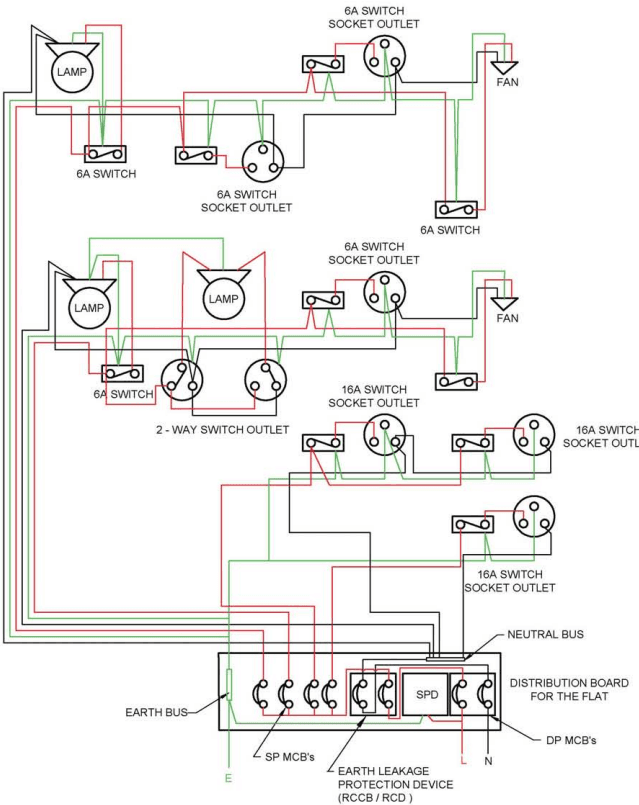
5.4.4.3 It is preferable to have additional circuit for kitchen and bathrooms. Such sub-circuit shall not have more than a total of ten points of light, fans and 6 A socket outlets. The load of such circuit shall be restricted to 800 W and the wiring with 1.5 mm² copper conductor cable is recommended. If a dedicated circuit is planned for light fixtures, the load of such circuit shall be restricted to 400 W and the wiring with 1.5 mm² copper conductor cable is recommended. If a dedicated circuit is planned for 6A sockets the load of such a circuit shall be restricted to 800 W or a maximum of 8 numbers, whichever is lesser, controlling MCB should be sized accordingly. The wiring shall be with 1.5 mm² copper conductor cable. If a separate fan circuit is provided, the number of fans in the circuit shall not exceed ten. Power sub-circuit shall be designed according to the load but in no case shall there be more than two 16 A outlets on each sub-circuit which can be wired with 4 mm² for miscellaneous socket loads and shall be with 4 mm² copper conductor cable for equipment consuming more than 1 kW. Power sockets
5.4.5 Location of Distribution Boards
a) The distribution boards shall be located as near as possible to the centre of the load they are intended to control.
b) These shall be fixed on suitable stanchion or wall and shall be accessible for replacement/reset of protective devices, and shall not be more than 1.8 m from floor level.
c) These shall be of either metal-clad type, or polycarbonate enclosure of minimum IP 42. But, if exposed to weather or damp situations, these shall be of the weatherproof type conforming to IP 55 and, if installed where exposed to explosive dust, vapour or gas, these shall be of flameproof type in accordance with accepted standards [8-2(26)]. In corrosive atmospheres, these shall be treated with anti-corrosive preservative or covered with suitable plastic compound.
d) Where two and/or more distribution boards feeding low voltage circuits are fed from a supply of medium voltage, the metal case shall be marked ‘Danger 415 Volts’ and identified with proper phase marking and danger marks.
e) Each shall be provided with a circuit list giving diagram of each circuit which it controls and the current rating of the circuit and size of fuse element.
f) In wiring branch distribution board, total load of consuming devices shall be divided as far as possible evenly between the number of ways in the board leaving spare circuits for future extension.
g) Distribution board shall not be located at structural expansion joints of the building.
h) Distribution board/other electrical outlets shall have a minimum calculated separation distance from lightning protection down-
conductors to avoid flash over in case of lightning.
j) Walls with flushed distribution boards shall have adequate support behind and surrounding so that there is no physical weight on the distribution board of the civil structure around. Electrical switch sockets, etc, shall also be avoided to be mounted behind the distribution board to avoid touching the board from behind.
5.4.6 Protection of Circuits
a) Appropriate protection shall be provided at switchboards, distribution boards and at all levels of panels for all circuits and sub-circuits against short circuit, over-current and other parameters as required. The protective device shall be capable of interrupting maximum prospective short circuit current that may occur, without danger. The ratings and settings of fuses and the protective devices shall be coordinated so as to afford selectivity in operation and in accordance with accepted standards [8-2(27)].
b) Where circuit-breakers are used for protection of a main circuit and of the sub-circuits derived therefrom, discrimination in operation may be achieved by adjusting the protective devices of the sub-main circuit-breakers to operate at lower current settings and shorter time-lag than the main circuit-breaker.
c) Where HRC type fuses are used for back-up protection of circuit-breakers, or where HRC fuses are used for protection of main circuits, and circuit-breakers for the protection of sub-circuits derived there from, in the event of short-circuits protection exceeding the short-circuits protection exceeding the short-circuits capacity of the circuit-breakers, the HRC fuses shall operate earlier than the circuit-breakers; but for smaller overloads within the short-circuit capacity of the circuit-breakers, the circuit-breakers shall operate earlier than the HRC fuse blows.
d) If rewireable type fuses are used to protect sub-circuits derived from a main circuit protected by HRC type fuses, the main circuit fuse shall normally blow in the event of a short-circuit or earth fault occurring on sub-circuit, although discrimination may be achieved in respect of overload currents. The use of rewireable fuses is restricted to the circuits with short-circuit level of 4 kA; for higher level either cartridge or HRC fuses shall be used. However, use of rewireable fuse is not desirable, even for lower fault level areas. MCB's provide a better and dependable
protection, as their current setting is not temperable.
e) A fuse carrier shall not be fitted with a fuse element larger than that for which the carrier is designed.
f) The current rating of a fuse or circuit breaker shall not exceed the current rating of the smallest cable in the circuit protected by the fuse.
g) Every fuse shall have its own case or cover for the protection of the circuit and an indelible indication of its appropriate current rating in an adjacent conspicuous position.
h) All distribution board or panel incomer may be protected by a surge protection device, if found necessary (see 11). Separate HRC fuse/CB with proper enclosure may be required in series with the surge protection device with main incomer. Back-up fuse/CB shall be of the capacity not lower than that recommended by the SPD manufacturer. Short circuit withstand capability of the SPDs should be coordinated with the HRC fuse/CB and SPD should be selected to be matching the fault power expected/calculated at that point.
5.4.7 Cascading, Discrimination and Limitation
Cascading and discrimination in switchgear downstream and upstream shall be designed and maintained such that the continuity of power in case of any abnormal conditions such as overload, short circuit and earth faults, etc is maintained and only faulty circuit is isolated and power is made available to other loads.
Cascading technique allows the designer to select circuit breakers of lower breaking capacities. Utilizing the current limiting effect of the incoming breaker, outgoing breaker can sustain the higher faults than its capacity and even maintain the discrimination.
5.5 Protection Class of Equipment and Accessories
The class of ingress protection (IP) and protection against mechanical impact (IK) {see also good practice [8-2(6)] and IEC 62262:2002 'Degrees of protection provided by enclosures for electrical equipment against external mechanical impacts (IK code)} shall be specific depending on the requirement at the place of installation.
5.7Rating of Cables and Equipment
5.7.1 The current-carrying capacity of different types of cables shall be chosen in accordance with good practice [8-2(28)].
5.7.2 The current ratings of switches for domestic and similar purposes are 6 A, 16 A, 20 A and 25 A.
5.7.3 The current ratings of isolators and normal duty switches and composite units of switches and fuses shall be selected from one of the following values:
16, 25, 32, 63, 100, 160, 200, 320, 400, 500, 630, 800, 1 000 and 1 250 A.
5.7.4 The ratings of rewireable and HRC fuses shall be in accordance with good practice [8-2(29)].
5.7.5 The current ratings of miniature circuit-breakers shall be chosen from the values given below:
5.7.7 The current ratings of air circuit-breakers shall be chosen from the values given below:
630, 800, 1 000, 1 250, 1 600, 2 000, 2 500, 3 200, 4 000A and 6 300 A.
5.7.8 The current ratings of the distribution fuse board shall be selected from one of the following values:
6, 16, 25, 32, 63 and 100A.
5.8 Installation Circuits
5.8.1 The nominal cross-sectional area of copper phase conductors in a.c. circuits and of live conductors in d.c. circuits shall be not less than the values specified below:
Sl No.
Type of Circuit
Minimum Copper Wire Size
Number of Circuits
(1)
(2)
(3)
(4)
i)
Lighting
1.5 mm²
2 or more
ii)
Socket-outlets, 6 A
2.5 mm²
Any numberAreas such as kitchens and laundries 3 × double socket-outlets per circuit. Other areas up to 12 double socket-outlets
iii)
Signaling and control circuits
0.5 mm²(see Note 1)
—
iv)
Socket-outlets, 16 A
2.5 mm²
1
v)
Water heater < 3 kW
2.5 mm²
1
vi)
Heaters or electric equipment more than or equal to 3 kW
4.0 mm²
1
vii)
Free standing electric rangeSeparate oven and/or cook top
4.0 mm²
1
viii)
Air conditioner > 1.5 t
4.0 mm²
1
ix)
Permanently connected appliances including dishwashers, heaters, etc
2.5 mm²
1 above 10 A. Up to 10 A can be wired as part of a socket-outlet circuit
x)
Appliance rated >3 kW<6 kW
6.0 mm²
—
xi)
Submains to garage or out-building
2.5 mm²
1 for each
xii)
Mains cable
—
It should be based on demand load/peaking loads and future loading.
NOTE — In multi-core flexible cables containing 7 or more cores and in signalling control circuits intended for electronic equipment a minimum nominal cross-sectional area of 0.1mm² is permitted.
5.8.2 Aluminum conductor cables in sizes less than 16 mm² cause termination problems leading to heating at the terminals and enhance the possibility of a fire. For conductor sizes less than or equal to 16 mm² , only copper conductor cables should be used.
5.8.3 Switch or isolator controlling a water heater or geyser should not be located within 1 m from the location of a shower or bath tub, to avoid a person in wet condition reaching the switch or isolator. It is preferable to provide the control switch outside the bath room near the entrance and provide an indication at the water heater. A socket or a connector block with suitable protection against water spray should be provided to connect the water heater. The above considerations apply to switches for outdoor lights and other appliances, with the objective of avoidance of operation of a switch when a person is wet.
5.8.4 Sockets in kitchen, bathroom, toilet, garage, etc, should not be provided within a height of 1m from the ground level. Similar care has to be taken for installations
involving fountains, swimming pools, etc. Light fittings in such areas should be fed at low voltage, preferably through an isolating transformer with a proper earth leakage protection. Where possibility of a person in contact with a wet surface has to operate or touch an electrical switch or an appliance the circuit should be protected by a 100/30 mA RCCB/RCD, as applicable.
5.8.5 Selecting and Installing Cables
5.8.5.1 Cable insulation types
For the purpose of this Code, cables above 1 mm² shall have stranded conductors. All cables when installed, shall be adequately protected against mechanical damage. This can be carried out by either having additional protection, such as being enclosed in PVC conduit or metal pipes, or placing the cables in a suitable location that requires no additional protection. The cables for wiring circuits in electrical installation shall have the appropriate wire size matching the requirement of the loads and the following table gives the recommendations for different types of loads:
For the mains cable
Tough plastic sheathed (TPS) cable
For installation wiring
Tough plastic sheathed (TPS) cables
For main earth or main equipotential wire
Poly vinyl chloride (PVC) insulated conduit wire
Underground installation and installation in cable trench, feeders between buildings, etc
Recommended minimum wire sizes for various circuits is given below:
Sl No.
Circuits
Minimum Wire Size
Wire Colour
(1)
(2)
(3)
(4)
i)
1-way lighting
2 + E cable wires1.5 mm²
Red-Black-Green or Green/Yellow
ii)
2-way lighting control (straps between the 2 switches)
3 wire cable1.5 mm²
Red-White-Blue
iii)
Storage water heaters up to 3 kW
2 + E cable2.5 mm² (stranded conductors)
Red-Black-Green or Green/Yellow
iv)
Storage water heaters between 3 kW and 6 kW
2 + E cable4 mm² (stranded conductors)
Red-Black-Green or Green/Yellow
v)
Socket-outlets and permanent connection units
2 + E cable2.5 mm² (stranded conductors)
Red-Black-Green or Green/Yellow
5.9Lighting and Levels of Illumination
5.9.1 General
Lighting installation shall take into consideration many factors on which the quality and quantity of artificial lighting depends. Recent practice in illumination is to provide the required illumination with a large number of light sources (not of higher illumination level) instead of fewer number of light sources of higher illumination level, to produce higher uniformity in illumination level.
Now a wide variety of light sources, such as, fluorescent lamps [tubular (TL) and compact (CFL)], light emitting diodes (LED) and induction lighting are available in addition to the incandescent lamps (GLS and halogen), for application in buildings. Most of them are competitive when applied in the segment for which a particular type is well suited.
With the increase in energy costs and awareness of the need to conserve energy for the protection of the
environment, lighting design is becoming complex. With the developments in the types of light sources and their control systems now available, lighting design goes with the concept of better light with less energy and least impact on environment.
Automatic lighting control schemes may be considered to have efficient utilization of lights. Automatic controls can take care of the switching off when the space served has no activity or is illuminated by daylight.
5.9.2 Electrical Installations for Lighting
The concepts or needs of energy conservation today require more lights to be provided so that different sets of lights are used to light up the area of activity to the required higher level of lighting needed for the activity and provide a general minimum background level of lighting. Any space requires two or three different combination of lighting sets associated with the activity and this may require the wiring to be provided to accommodate the lighting groups in different circuits with group controls, automatic controls and remote controls.
Availability of LED lights with a wide range from 1 W to 100 W allows designers to provide spot task lighting of a high illumination level combined with a general space lighting of low illumination. As light follows the inverse square law, provision of the light source close to the task reduces the energy need.
Lighting demand for buildings should be considered as per type of building. Where nothing is specified, for lighting demand of any type of building a maximum of 13 W/m² of all built-up areas including balconies. Covered parking areas may be considered at 3.23 W/m² including balconies, service areas, corridors, etc, may be considered with very basic diversity of 80 percent to 100 percent. Power requirements shall be considered at least 55 W/m² with an overall diversity not exceeding 50 percent. These shall be excluding defined loads such as lifts, plumbing system, fire fighting systems, ventilation requirement, etc.
While incandescent lamps (GLS or halogen) does not require any control gear, other light sources such as tubular fluorescent lamps, compact fluorescent lamps, mercury vapour lamps, sodium vapour lamps, metal halide lamps and light emitting diode (LED) lamps have non-linear characteristics and require specifically made control gear for each type of lamp for their proper operation. In some cases the control gear is integral with the lamp and in some it is with light fitting and in some it is external. The electrical installation and wiring has to take this into account and provide appropriate space for such control gear. There will be heat emission, introduction of harmonics etc, and they also consume some energy. The electrical and lighting system design has to keep this aspect in the wiring design and
installation. Control gear contributes or influences energy conservation significantly and due care should be taken to ensure a proper choice.
5.9.3 Principles of Lighting
When considering the function of artificial lighting, attention shall be given to the following principle characteristics before designing an installation:
a) Illumination and its uniformity;
b) Special distribution of light. This includes a reference to the composition of diffused and directional light, direction of incidence, the distribution of luminances and the degree of glare;
c) Colour of the light and colour rendition;
d) Natural light sources, if possible such as light tubes; and
e) System wattage of the luminaire proposed.
5.9.4 The variety of purposes which have to be kept in mind while planning the lighting installation may be broadly grouped as:
a) Industrial buildings and processes;
b) Offices, schools and public buildings;
c) Surgeries and hospitals; and
d) Hostels, restaurants, shops and residential buildings.
5.9.4.1 It is important that appropriate levels of illumination for these and the types and positions of fittings determined to suit the task and the disposition of the working planes.
5.9.5 For detailed requirements for lighting and lighting design and installations, reference shall be made to National Lighting Code. For specific requirements for lighting of special occupancies, reference shall be made to good practice [8-2(30)] and the National Lighting Code.
5.9.6 Energy Conservation
Energy conservation may be achieved by using the following:
a) Energy efficient lamps, chokes, ballast, etc, for lighting equipment.
b) Efficient switching systems such as remote sensors, infrared switches, master switches, occupancy sensors, light sensors, light automation, remote switches, etc for switching ‘ON’ and ‘OFF’ of lighting circuits.
c) Properly made/connected joints/contacts to avoid loose joints leading to loss of power.
5.10 In locations where the system voltage exceeds 650V, as in the case of industrial locations, for details of design and construction of wiring installation,
Book Supply Bureau Under the License from BIS for LARSEN AND TOUBRO CONSTRUCTION - MANAPAKKAM, CHENNAI ON 17-03-2017 09:00:59 (123.63.84.35) valid u
reference may be made to good practice [8-2(11)].
5.11 Guideline for Electrical Layout in Residential Buildings
For guidelines for electrical installation in residential buildings, reference may be made to good practice [8-2(31)].
A typical distribution scheme in a residential building with separate circuits for lights and fans and for power appliances is given in Fig. 3.
5.12 For detailed information regarding the installation of different electrical equipment, reference may be made to good practice [8-2(32)].
6Wiring
6.1 Provision for Maximum Load
All conductors, switches and accessories shall be of such size as to be capable of carrying, without their respective ratings being exceeded, the maximum current which will normally flow through them.
6.1.1 Estimation of Load Requirements
In estimating the current to be carried by any conductor the following ratings shall be taken, unless the actual values are known or specified for these elements:
SlNo.(1)
Element(2)
RatingW(3)
i)
Incandescent lamp
60
ii)
Ceiling fan
60
iii)
Table fan
60
iv)
6 A socket outlet
100, unless the actual value of loads are specified
v)
16 A socket outlet
1 000, unless the actual value of loads are specified
High pressure mercury vapour (HPMV) lamps, high pressure sodium vapour (HPSV) lamps
According to their capacity, control gear losses shall be also considered as applicable
viii)
Compact fluorescent lamp (CFL)
20
ix)
Light emitting diode (LED)
10
SlNo.(1)
Element(2)
RatingW(3)
x)
Exhaust fan
50
xi)
Geyser (storage type)
2 000
xii)
Geyser (instant)
3 000
xiii)
Computer point
150
xiv)
Computer (laptop)
50
xv)
Printer, laser
1 500
xvi)
Printer, inkjet
70
xvii)
Kitchen outlet
1 500
xviii)
Air conditioner:
1 TR
1 250
1.5 TR
1 875
2 TR
2 500
2.5 TR
3 200
6.1.2 Electrical installation in a new building shall normally begin immediately on the commencement of the main structural building work and before finishing work such as plastering has begun except in the case of surface wiring which can be carried out after the plaster work. Usually, no installation work should start until the building is reasonably weatherproof, but where electric wiring is to be concealed within the structures as may be the case with a reinforced concrete building, the necessary conduits and ducts shall be positioned firmly by tying the conduit to the reinforcement before concreting. Care should be taken to avoid use of damaged conduit or ducts, the conduits end shall be given suitable anti-corrosive treatment and holes blocked off by putties or caps to protect conduits from getting blocked. All conduit openings and junction box openings, etc shall be properly protected against entry of mortar, concrete, etc, during construction.
6.2Selection of Size of Conductors
The size of conductors of circuits shall be so selected that the drop in voltage from consumer's terminals in a public supply (or from the bus-bars of the main switchboard controlling the various circuits in a private generation plant) to any point on the installation does not exceed three percent of the voltage at the consumer's terminals (or at two bus-bars as these may be) when the conductors are carrying the maximum current under the normal conditions of service. The overall voltage drop from the transformer end to consumer's final distribution board shall not exceed six percent.
6.2.1 If the cable size is increased to reduce voltage drop in the circuit, the rating of the cable shall be sufficient to carry the current which the circuit is designed for. In each circuit or sub-circuit the fuse/circuit-breaker shall be selected to match the current rating of the circuit to ensure the desired protection.
FIG. 3 WIRING DIAGRAM FOR A TYPICAL DISTRIBUTION SCHEME IN A RESIDENTIAL BUILDING FLAT
48
6.3 Branch Switches
Where the supply is derived from a three-wire or four-wire source, and distribution is done on the two-wire system, all branch switches shall be placed in the outer or live conductor of the circuit and no single phase switch or protective device shall be inserted in the middle wire, earth or earthed neutral conductor of the circuit. Single-pole switches (other than for multiple control) carrying not more than 16 A may be of tumbler type or flush type which shall be on when the handle or knob is down.
6.4Layout and Installation Drawing
6.4.1 The electrical layout should be drawn indicating properly the locations of all outlets, such as, lamps, fans, appliances (both fixed and movable) and motors and best suit for wiring.
6.4.2 All runs of wiring and the exact positions of all points of switch-boxes and other outlets shall be first marked on the plans of the building and approved by the Engineer-in-Charge or the owner before actual commencement of the work.
6.4.3 Industrial layout drawings should indicate the relative civil and mechanical details.
6.4.4 Layout of Wiring
The layout of wiring should be designed keeping in view disposition of the lighting system to meet the illumination levels. All wirings shall be done on the distribution system with main and branch distribution boards at convenient physical and electrical load centres. All types of wiring, whether concealed or unconcealed should be as near the ceiling as possible. In all types of wirings due consideration shall be given for neatness and good appearance.
6.4.5 Balancing of circuits in three-wire or poly-phase installation shall be arranged beforehand. Proper balancing can be done only under actual load conditions. Conductors shall be so enclosed in earthed metal or incombustible insulating material that it is not possible to have ready access to them. Means of access shall be marked to indicate the voltage present.
Where terminals or other fixed live parts between which a voltage exceeding 250 V exists are housed in separate enclosures or items of apparatus which, although separated are within reach of each other, a notice shall be placed in such a position that anyone gaining access to live parts is warned of the magnitude of the voltage that exists between them.
Where loads are single phase, balancing should be for the peak load condition based on equipment usage. Facility for change should be built into the distribution design.
NOTE — The above requirements apply equally to three-phase circuits in which the voltage between lines or to earth exceeds 250 V and to groups of two or more single-phase circuits, between which medium voltage may be present, derived therefrom. They apply also to 3-wire d.c. or 3-wire single-phase a.c. circuits in which the voltage between lines or to earth exceeds 250 V and to groups of 2-wire circuits, between which medium voltage may be present, derived there from.
6.4.6 Medium voltage wiring and associated apparatus shall comply, in all respects, with the requirements of Regulation 35, 36, 37, 40, 41 and 42 of Central Electricity Authority (Measures Relating to Safety and Electricity Supply) Regulations, 2010, as amended from time-to-time (see Annex B).
6.5Conductors and Accessories
6.5.1 Conductors
Conductors for all the internal wiring shall be of copper. Conductors for power and lighting circuits shall be of adequate size to carry the designed circuit load without exceeding the permissible thermal limits for the insulation. For final section wiring to larger loads, the current carrying capacity will preside. The conductor size shall also be based on the voltage drop in the line so as to provide a terminal voltage not below the prescribed voltage requirement.
The conductor for final sub-circuit for fan and light wiring shall have a nominal cross-sectional area not less than 1.50 mm² copper. The cross-sectional area of conductor for power wiring shall be not less than 2.5 mm² copper. The minimum cross-sectional area of conductor of flexible cord shall be 1.50 mm² copper.
In existing buildings where aluminum wiring has been used for internal electrification, changeover from aluminum conductor cables to copper conductor cables is recommended as it has been found that aluminum conductors below 10 mm² size pose a number of hazards.
NOTE — It is advisable to replace wiring, which is more than 30 years old as the insulation also would have deteriorated, and will be in a state to cause failure on the slightest of mechanical or electrical disturbance.
6.5.2 Flexible Cables and Flexible Cords
Flexible cables and cords shall be of copper and stranded and protected by flexible conduits or tough rubber or PVC sheath to prevent mechanical damage.
6.5.3 Cable Ends
When a stranded conductor having a nominal sectional area less than 6 mm² is not provided with cable sockets, all strands at the exposed ends of the cable shall be soldered together or crimped using suitable sleeve or ferrules.
6.5.4 Special Risk
Special forms of construction, such as flameproof
enclosures, shall be adopted where there is risk of fire or explosion.
6.5.5 Connection to Ancillary Buildings
Unless otherwise specified, electric connections to ancillary buildings, such as out-houses, garages, etc, adjacent to the main building and when no roadway intervenes shall be taken in an earthed GI pipe or heavy duty PVC or HDPE pipe of suitable size. This pipe can be taken either underground or over ground, however, in latter case, its height from the ground shall not be less than 5.8 m. This applies to both runs of mains or sub-mains or final sub-circuit wiring between the buildings.
6.5.6 Expansion Joints
Distribution boards shall be so located that the conduits shall not normally be required to cross expansion joints in a building. Where such crossing is found to be unavoidable, special care shall be taken to ensure that the conduit runs and wiring are not in any way put to strain or damaged due to expansion of building structure. Anyone of the following standard methods of connection at a structural expansion joint shall be followed:
a) Flexible conduit shall be inserted at place of expansion joint.
b) Oversized conduit overlapping the conduit.
c) Expansion box.
Supports and flexible joints shall be of same requirement as the rising main/bus duct in so far as resistance to seismic forces is concerned. This is further important when rising mains and bus-ducts cross expansion joints.
6.5.7 Low Voltage (Types of Wires/Cables)
Low voltage services utilizes various categories of cables/wires, such as fibre optic cable, co-axial, category cable, etc. These shall be laid at least at a distance of 300 mm from any power wire or cable. The distance may be reduced only by using completely closed earthed metal trunking with metal separations for various kind of cable. Special care shall be taken to ensure that the conduit runs and wiring are laid properly for low voltage signal to flow through it.
The power cable and the signal or data cable may run together under floor and near the equipment. However, separation may be required from the insulation aspect, if the signal cable is running close to an un-insulated conductor carrying power at high voltage. All types of signal cables are required to have insulation level for withstanding 2 kV impulse voltage even if they are meant for service at low voltage.
6.6Joints and Looping Back
6.6.1 Where looping back system of wiring is specified, the wiring shall be done without any junction or connector boxes on the line. Where joint box system is specified, all joints in conductors shall be made by means of suitable mechanical connectors in suitable joint boxes. Whenever practicable, only one system shall be adopted for a building, preferably a looping back system.
6.6.2 In any system of wiring, no bare or twist joints shall be made at intermediate points in the through run of cables unless the length of a final sub-circuit, sub-main or main is more than the length of the standard coil as given by the manufacturer of the cable. If any jointing becomes unavoidable such joint shall be made through proper cutouts or through proper junction boxes open to easy inspection, but in looping back system no such junction boxes shall be allowed.
6.6.3 Joints are a source of problems in reliability and are also vulnerable to fire. They should be avoided or at least minimized. They should under no circumstance exceed more than one to two in total length and distance between two shall not be less than 5 m. Joint should not be used as tap-off for multiple feeders. Where joints in cable conductors or bare conductors are necessary, they shall be mechanically and electrically sound. Joints in non-flexible cables shall be accessible for inspection; provided that this requirement shall not apply to joints in cables buried underground, or joints buried or enclosed in non-combustible building materials. Joints in non-flexible cables shall be made by soldering, brazing, welding or mechanical clamps, or be of the compression type; provided that mechanical clamps shall not be used for inaccessible joints buried or enclosed in the building structure. All mechanical clamps and compression type sockets shall securely retain all the wires of the conductors. Any joint in a flexible cable or flexible cord shall be effected by means of a cable coupler.
For flexible cables for small loads less than 1 kW, while it is desirable to avoid joints, if unavoidable, joints may be made either by splicing by a recognized method or by using a connector and protecting the joint by suitable insulating tape or sleeve or straight joint. For application of flexible cable for loads of 1 kW or more, if joint is unavoidable, crimped joint is preferred. Spliced joint should not be used for large loads.
There are different standard joints, such as epoxy resin based joint, heat shrinkable plastic sleeve joint, etc, and each one has its advantage and disadvantage. Selection has to be made on the basis of application, site conditions and availability of skilled licensed workmen trained in the application of the particular type of joint.
6.6.4 Every joint in a cable shall be provided with insulation not less effective than that of the cable cores and shall be protected against moisture and mechanical damage. Soldering fluxes which remain acidic or corrosive at the completion of the soldering operation shall not be used.
For joints in paper-insulated metal-sheathed cables, a wiped metal sleeve or joint box, filled with insulating compound, shall be provided.
Where an aluminum conductor and a copper conductor are joined together, precautions shall be taken against corrosion and mechanical damage to the conductors.
6.6.5 Pull at Joints and Terminals
Every connection at a cable termination shall be made by means of a terminal, soldering socket, or compression type socket and shall securely contain and anchor all the wires of the conductor, and shall not impose any appreciable mechanical strain on the terminal or socket.
Flexible cords shall be so connected to devices and to fittings that tension is not transmitted to joints or terminal screws. This shall be accomplished by a knot in the cord, by winding with tape, by a special fitting designed for that purpose, or by other approved means which can prevent a pull on the cord from being directly transmitted to joints or terminal screws.
6.7Passing Through Walls and Floors
6.7.1 Where wires/cables are required to pass through walls, care shall be taken to see that wires/cables pass freely through protective pipe or box and that the wires pass through in a straight line without any twist or cross in wires.
One of the following methods shall be employed for laying wires/cables:
a) Conduit wiring system (see 6.10) — The conductor shall be carried either in a rigid steel conduit or a rigid non-metallic conduit conforming to accepted standards [8-2(33)].
The conduits shall be colour coded as per the purpose of wire carried in the same. The recommended colour coding may be in form of bands of colour (100 mm thick, with centre to centre distance of 300 mm) or coloured throughout. The colour scheme may be as follows:
Conduit Type
Colour Scheme
Power conduit
Black
Security conduit
Blue
Fire alarm conduit
Red
Low voltage conduit
Brown
UPS conduit
Green
Conduit wiring system shall comply with accepted standards [8-2(34)]. The number of insulated conductors that can be drawn into rigid conduit is given in Tables 1 (see Table 1A for rigid steel conduits and Table 1B for rigid non-metallic conduits).
Cable trunking/cable ways (see 6.11) — Cable trunking/cable ways system should be used when number of wires/small cable sizes to be laid is more than the conduit capacity. Care should be taken to have space in the trunking system to minimize heating of wires and to provide identification of the different circuits. Cable trunking or ducting system shall comply with accepted standards [8-2(35)].
c) Tray and ladder rack — As tray provides continuous support, unless mounted on edge or in vertical runs (when adequate strapping or clipping is essential), the mechanical strength of supported cable is not as important as with ladder-racking or structural support methods. Consequently, tray is eminently suitable for the smaller unarmoured cabling while ladder racks call for armoured cables or larger unarmoured cables as they provide the necessary strength to avoid sagging between supports. Both tray and ladder racks are provided with accessories to facilitate changes of route, and they provide no difficulty in this respect on vertical runs.
Cable tray/ladder racks and support systems shall be installed in such a way that the deflection between the spans shall be less than 1 percent of the span.
Power cables running in cable ladders both horizontal and vertical shall be fixed with proper clamps which can withstand the mechanical force created on the cable in case of short circuit current. The complete installation consisting of cables, ladders, clamps, ladder supports and fixtures shall also withstand the mechanical force of short circuit current. Only one layer of power cable shall be laid in a ladder. The minimum space between two cables shall be equal to the diameter of the biggest cable.
Cable tray and ladder system shall comply with IEC 61537:2006 ‘Cable management — Cable tray systems and cable ladder systems’ (under publication as an adopted Indian Standard).
6.7.2 Insulated conductors while passing through floors shall be protected from mechanical injury by means of rigid steel/non-metal conduit or by mechanical protection up to a height not less than 1.5m above the
floor and flush with the ceiling below. These steel conduits shall be earthed and securely bushed.
Power outlets and wiring in the floor shall be generally avoided. If not avoidable, false floor trunking or metal floor trunking should be used. Power sockets of adequate IP/IK rating shall be used.
False floor shall be provided where density of equipment and interconnection between different pieces of equipment is high. Examples are, mainframe computer station, telecommunication switch rooms, etc. Floor trunking shall be used in large halls, convention centres, open plan offices, laboratory, etc.
In case of floor trunking, drain points/weep holes shall be provided within the trunking for installation for conventional centres, exhibition areas or any other place where water may spill into the trunking, as there might be possibility of water seepage in the case of wiring passing through the floors. Proper care should be taken for providing suitable means of draining of water. Possibility of water entry exists from floor washing, condensation in some particular weather and indoor temperature conditions. At the design stage, these aspects shall be assessed and an appropriate means of avoiding, or reducing, and draining method shall be built in. Floor trunking outlets shall be suitably IP rated for protection against dust and water.
Floor outlet boxes are generally provided for the use of appliances, which require a signal, or communication connection. The floor box and trunking system should cater to serve both power distribution and the signal distribution, with appropriate safety and non-interference.
6.7.3 Where a wall tube passes outside a building so as to be exposed to weather, the outer end shall be bell-mouthed and turned downwards and properly bushed on the open end.
6.8Wiring of Distribution Boards
6.8.1 All connections between pieces of apparatus or between apparatus and terminals on a board shall be neatly arranged in a definite sequence, following the arrangements of the apparatus mounted thereon, avoiding unnecessary crossings.
6.8.2 Cables shall be connected to a terminal only by soldered or welded or crimped lugs using suitable sleeve, lugs or ferrules unless the terminal is of such a form that it is possible to securely clamp them without the cutting away of cables stands. Cables in each circuit shall be bunched together.
6.8.3 All bare conductors shall be rigidly fixed in such a manner that a clearance of at least 25 mm is maintained between conductors or opposite polarity or
phase and between the conductors and any material other than insulation material.
6.8.4 If required, a pilot lamp shall be fixed and connected through an independent single pole switch and fuse to the bus-bars of the board. Leads connecting bus-bars to any instrument or indicating lamp or an outgoing connection switch or breaker face the same fault current that is applicable to the bus-bar and as such should be provided with a fuse capable of handling the prospective fault current.
6.8.5 In a hinged type board, the incoming and outgoing cables shall be fixed at one or more points according to the number of cables on the back of the board leaving suitable space in between cables, and shall also, if possible, be fixed at the corresponding points on the switchboard panel. The cables between these points shall be of such length as to allow the switchboard panel to swing through an angle of not less than 90° and cables arranged and clamped in such a manner that the cables do not face bending, but only face a twist, when the hinged door is opened. The circuit breakers in such cases shall be accessible without opening the door of distribution board. Also, circuit breakers or any other equipment (having cable size more than 1.5 mm² multi-strand wire) shall not be mounted on the door.
NOTE — Use of hinged type boards is discouraged, as these boards lead to deterioration of the cables in the hinged portion, leading to failures or even fire.
6.8.6 Wires terminating and originating from the protective devices shall be properly lugged and taped.
6.9PVC-Sheathed Wiring System
6.9.1 General
Wiring with PVC-sheathed cables may be used for temporary installations for medium voltage installation and may be installed directly under exposed conditions of sun and rain or damp places.
6.9.2 PVC Clamps/PVC Channel
The clamps shall be used for temporary installations of 1-3 sheathed wires only. The clamps shall be fixed on wall at intervals of 100 mm in the case of horizontal runs and 150 mm in the case of vertical runs.
PVC channel shall be used for temporary installations in case more than 3 wires or wires or unsheathed wires. The channel shall be clamped on wall at intervals not exceeding 300 mm. PVC clamps/PVC channel shall conform to accepted standards.
6.9.3 Protection of PVC-Sheathed Wiring from Mechanical Damage
a) In cases where there are chances of any damage to the wirings, such wirings shall be
52
covered with sheet metal protective covering, the base of which is made flush with the plaster or brickwork, as the case may be, or the wiring shall be drawn through a conduit complying with all requirements of conduit wiring system (see 6.10).
b) Such protective coverings shall in all cases be fitted on all down-drops within 1.5m from the floor.
6.9.4 Bends in Wiring
The wiring shall not in any circumstances be bent so as to form a right angle but shall be rounded off at the corners to a radius not less than six times the overall diameter of the cable.
6.9.5 Passing Through Floors
All cables taken through floors shall be enclosed in an insulated heavy gauge steel conduit extending 1.5 m above the floor and flush with the ceiling below, or by means of any other approved type of metallic covering. The ends of all conduits or pipes shall be neatly bushed with porcelain, wood or other approved material.
6.9.6 Passing Through Walls
The method to be adopted shall be according to good practice. There shall be one or more conduits of adequate size to carry the conductors [see 6.10.1(a)]. The conduits shall be neatly arranged so that the cables enter them straight without bending.
6.9.7 Stripping of Outer Covering
While cutting and stripping of the outer covering of the cables, care shall be taken that the sharp edge of the cutting instrument does not touch the rubber or PVC-sheathed insulation of conductors. The protective outer covering of the cables shall be stripped off near connecting terminals, and this protective covering shall be maintained up to the close proximity of connecting terminals as far as practicable. Care shall be taken to avoid hammering on link clips with any metal instruments, after the cables are laid. Where junction boxes are provided, they shall be made moisture-proof with an approved plastic compound.
6.9.8 Painting
If so required, the tough rubber-sheathed wiring shall, after erection, be painted with one coat of oil-less paint or distemper of suitable colour over a coat of oil-less primer, and the PVC-sheathed wiring shall be painted with a synthetic enamel paint of quick drying type.
6.10Conduit Wiring System
Conduit wiring system shall comply with accepted standards [8-2(34)]. Requirements relating to conduit
wiring system with rigid steel and non-metallic conduits shall be as per 6.10.1 to 6.10.3.
6.10.1 Surface Conduit Wiring System with Rigid Steel Conduits
a) Type and size of conduit — All conduit pipes shall conform to accepted standards [8-2(36)], finished with galvanized or enamelled surface. All conduit accessories shall be of threaded type and under no circumstance pin grip type or clamp type accessories be used. No steel conduit less than 16 mm in diameter shall be used. The number of insulated conductors that can be drawn into rigid steel conduit is given in Tables 1A.
b) Bunching of cables — Unless otherwise specified, insulated conductors of a.c. supply and d.c. supply shall be bunched in separate conduits. For lighting and small power outlet circuits phase segregation in separate conduits is recommended.
c) Conduit joints — Conduit pipes shall be joined by means of screwed couplers and screwed accessories only [see 8-2(37)]. In long distance straight runs of conduit, inspection type couplers at reasonable intervals shall be provided or running threads with couplers and jam-nuts (in the latter case the bare threaded portion shall be treated with anti-corrosive preservative) shall be provided. Threaded on conduit pipes in all cases shall be between 11 mm and 27 mm long sufficient to accommodate pipes to full threaded portion of couplers or accessories. Cut ends of conduit pipes shall have no sharp edges or any burrs left to avoid damage to the insulation of conductors while pulling them through such pipes.
d) Protection against dampness — In order to minimize condensation or sweating inside the tube, all outlets of conduit system shall be properly drained and ventilated, but in such a manner as to prevent the entry of insects as far as possible.
e) Protection of conduit against rust — The outer surface of the conduit pipes, including all bends, unions, tees, conduit system shall be adequately protected against rust particularly when such system is exposed to weather. In all cases, no bare threaded portion of conduit pipe shall be allowed unless such bare threaded portion is treated with anti-corrosive preservative or covered with suitable plastic compound.
f) Fixing of conduit — Conduit pipes shall be fixed by heavy gauge saddles, secured to
Table 1AMaximum Permissible Number of Single-Core Cables up to and including 1 100 V that can be Drawn into Rigid Steel Conduits [Clauses 6.7.1(a) and 6.10.1(a)]
Sl No.
Size of Cable
Size of Conduit mm
Nominal Cross-Sectional Area mm²
Number and Diameter (in mm) of Wires
16
20
25
32
40
50
63
S
B
S
B
S
B
S
B
S
B
S
B
S
B
(1)
(2)
(3)
(4)
(5)
(6)
(7)
(8)
(9)
(10)
(11)
(12)
(13)
(14)
(15)
(16)
(17)
i)
1.0
1/1.12¹⁾
5
4
7
5
13
10
20
14
—
—
—
—
—
—
ii)
1.5
1/1.40
4
3
7
5
12
10
20
14
—
—
—
—
—
—
iii)
2.5
1/1.80 3/1.06¹⁾
3
2
6
5
10
8
18
12
—
—
—
—
—
—
iv)
4
1/2.24 7/0.85¹⁾
3
2
4
3
7
5
12
10
—
—
—
—
—
—
v)
6
1/2.80 7/1.06¹⁾
2
—
3
2
6
5
10
8
—
—
—
—
—
—
vi)
10
1/3.55²⁾ 7/1.40¹⁾
—
—
2
—
5
4
8
7
—
—
—
—
—
—
—
—
2
—
4
3
6
5
8
6
—
—
—
For copper conductors only.
For aluminium conductors only.
suitable wood plugs or other plugs with screws in an approved manner at an interval of not more than 1 m, but on either side of couplers or bends or similar fittings, saddles shall be fixed at a distance of 300 mm from the centre of such fittings. Conduit fittings shall be avoided as far as possible on conduit system exposed to weather; where necessary, solid type fittings shall be used.
Bends in conduit — All necessary bends in the system including diversion shall be done by bending pipes; or by inserting suitable solid or inspection type normal bends, elbows or similar fittings; or fixing cast iron, thermoplastic or thermosetting plastic material inspection boxes, whichever is more suitable. Radius of such bends in conduit pipes shall be not less than 75 mm. No length of conduit shall have more than the equivalent of four quarter bends from outlet to outlet, the bends at the outlets not being counted.
h) Outlets — All outlets for fittings, switches, etc, shall be boxes of suitable metal or any other approved outlet boxes for either surface mounting or flush mounting system.
j) Conductors — All conductors used in conduit wiring shall preferably be stranded. No single-core cable of nominal cross-sectional area greater than 130 mm² enclosed along in a conduit and used for alternating current.
k) Erection and earthing of conduit — The conduit of each circuit or section shall be completed before conductors are drawn in. The entire system of conduit after erection shall be tested for mechanical and electrical continuity throughout and permanently connected to earth conforming to the requirements as already specified by means of suitable earthing clamp efficiently fastened to conduit pipe in a workman like manner for a perfect continuity between each wire and conduit. Gas or water pipes shall not be used
as earth medium. If conduit pipes are liable to mechanical damage they shall be adequately protected.
m) Inspection type conduit fittings, such as inspection boxes, draw boxes, bends, elbows and tees shall be so installed that they can remain accessible for such purposes as to withdrawal of existing cables or the installing of traditional cables.
6.10.2 Recessed Conduit Wiring System with Rigid Steel Conduit
Recessed conduit wiring system shall comply with all the requirements for surface conduit wiring system specified in 6.10.1 (a) to 6.10.1 (k) and in addition, conform to the requirements specified below:
a) Making of chase — The chase in the wall shall be neatly made and be of ample dimensions to permit the conduit to be fixed in the manner desired. In the case of buildings under construction, chases shall be provided in the wall, ceiling, etc, at the time of their construction and shall be filled up neatly after erection of conduit and brought to the original finish of the wall. In case of exposed brick/rubble masonry work, special care shall be taken to fix the conduit and accessories in position along with the building work.
b) Fixing of conduit in chase — The conduit pipe shall be fixed by means of staples or by means of saddles not more than 600 mm apart. Fixing of standard bends or elbows shall be avoided as far as practicable and all curves maintained by bending the conduit pipe itself with a long radius which will permit easy drawing-in of conductors. All threaded joints of rigid steel conduit shall be treated with preservative compound to secure protection against rust.
c) Inspection boxes — Suitable inspection boxes shall be provided to permit periodical inspection and to facilitate removal of wires, if necessary. These shall be mounted flush with the wall. Suitable ventilating holes shall be provided in the inspection box covers. The minimum sizes of inspection boxes shall be 75 mm × 75 mm .
d) Types of accessories to be used — All outlet, such as switches and wall sockets, may be either of flush mounting type or of surface mounting type, as given below:
Flush mounting type — All flush mounting outlets shall be of cast-iron or mild steel boxes with a cover of insulating material or shall be a box made of a suitable insulating material. The switches
and other outlets shall be mounted on such boxes. The metal box shall be efficiently earthed with conduit by a suitable means of earth attachment.
Surface mounting type — If surface mounting type outlet box is specified, it shall be of any suitable insulating material and outlets mounted in an approved manner.
The switches/socket outlets shall have adequate IP rating for various utilizations.
6.10.3 Conduit Wiring System with Rigid Non-Metallic Conduits
Rigid non-metallic conduits are used for concealed conduit wiring.
6.10.3.1 Type and size
All non-metallic conduits used shall conform to accepted standards [8-2(38)] and shall be used with the corresponding accessories {see accepted standards [8-2(39)]}. The conduits shall be circular or rectangular cross-sections.
6.10.3.2 Bunching of cables
6.11 Cable Trunking/Cable Ways
Cable trunking and ducting system of insulating
material are used for surface wiring. The number of insulated conductors that can be drawn into cable trunking and ducting system are given in Table 2.
7Fittings and Accessories
7.1 Ceiling Roses and Similar Attachments
7.1.1 A ceiling rose or any other similar attachment shall not be used on a circuit the voltage of which normally exceeds 250V.
7.1.2 Normally, only one flexible cord shall be attached to a ceiling rose. Specially designed ceiling roses shall be used for multiple pendants.
7.1.3 A ceiling rose shall not embody fuse terminal as an integral part of it.
7.2 Socket-Outlets and Plugs
Each 16 A socket-outlet provided in buildings for the use of domestic appliances, such as, air conditioner and water cooler shall be provided with its own individual fuse, with suitable discrimination with back-up fuse or miniature circuit-breaker provided in the distribution/sub-distribution board. The socket-outlet shall not necessarily embody the fuse as an integral part of it.
7.2.1 Each socket-outlet shall also be controlled by a switch which shall preferably be located immediately adjacent thereto or combined therewith.
7.2.2 The switch controlling the socket-outlet shall be on the live side of the line.
Table 2Maximum Permissible Number of PVC Insulated 650/1 100 V Grade Aluminium/Copper Cable Conforming to Accepted Standard [8-2(3)] that can be Drawn into Cable Trunking/Cable Ways (Clause 6.11)
Sl No.
Nominal Cross-Sectional Area of Conductormm²
10/15 mm × 10 mm
20/15 mm × 10 mm
25/15 mm × 16 mm
32 mm × 16 mm
40 mm × 25 mm
40 mm × 40 mm
(1)
(2)
(3)
(4)
(5)
(6)
(7)
(8)
i)
1.5
3
5
6
8
12
18
ii)
2.5
2
4
5
6
9
15
iii)
4
2
3
4
5
8
12
iv)
6
—
2
3
4
6
9
v)
10
—
1
2
3
5
8
vi)
16
—
—
1
2
4
6
vii)
25
—
—
—
1
3
5
viii)
35
—
—
—
—
2
4
ix)
50
—
—
—
—
1
3
x)
70
—
—
—
—
1
2
7.2.3 Ordinary socket-outlet may be fixed at any convenient place at a height above 200 mm from the floor level and shall be away from danger of mechanical injury.
NOTE — In situations where a socket-outlet is accessible to children, it is necessary to install an interlocked plug and socket or alternatively a socket-outlet which automatically gets screened by the withdrawal of plug. In industrial premises socket-outlet of rating 20 A and above shall preferably be provided with interlocked type switch.
In case of public buildings, to facilitate operation of switches/socket-outlets by persons with disabilities and the elderly, these shall be installed at an accessible height for reaching and operating, between 800 mm and 1 100 mm above floor level and shall be located at a minimum of 600 mm with a preference of minimum 700 mm, from any internal corner (see also B-7 of Part 3 ‘Development Control Rules and General Building Requirements’ of the Code). They shall be so fixed so as to be away from danger of mechanical injury.
NOTE — As an exception, electrical wall socket outlets, telephone points and TV sockets can be located at a minimum height of 400 mm above floor level.
7.2.4 In an earthed system of supply, a socket-outlet with plug shall be of three-pin or five-pin type with the third or fifth terminal connected to the earth. When such socket-outlets with plugs are connected to any current consuming device of metal or any non-insulating material or both, conductors connecting such current-consuming devices shall be of flexible cord with an earthing core and the earthing core shall be secured by connecting between the earth terminal of plug and the body of current-consuming devices.
In industrial premises three-phase and neutral socket-outlets shall be provided with a earth terminal either of
pin type or scrapping type in addition to the main pins required for the purpose.
7.2.5 In wiring installations for residential buildings, metal clad switch, socket-outlet and plugs shall be used for power wiring. For industrial and commercial application socket outlets conforming to accepted standards [8-2(25)] with suitable circuit breakers shall be used.
NOTE — A recommended schedule of socket-outlets in a residential building is given below:
Sl No.
Location
Number of 6 A Socket-Outlets
Number of 16 A Socket-Outlets
(1)
(2)
(3)
(4)
i)
Bed room
2 to 6
2
ii)
Living room
2 to 4
2
iii)
Kitchen
2 to 8
2
iv)
Dining room
2 to 4
2
v)
Garage
1
1
vi)
For refrigerator
—
1
vii)
For air conditioner
—
1 for each
viii)
Verandah
1 per 10 m²
1
ix)
Bathroom
1
1
7.3 Lighting Fittings
7.3.1 A switch shall be provided for control of every lighting fitting or a group of lighting fittings. Where control at more than one point is necessary as many two way or intermediate switches may be provided as there are control points. See also 7.2.3.
7.3.2 In industrial premises, lighting fittings shall be supported by suitable pipe/conduits, brackets fabricated from structural steel, steel chains or similar materials depending upon the type and weight of the fittings.
Where a lighting fitting is supported by one or more flexible cords, the maximum weight to which the twin flexible cords may be subjected shall be as follows:
SlNo.
Nominal Cross-Sectional Area of Twin Cordmm²
Maximum Permissible Weight kg
(1)
(2)
(3)
i)
0.5
2
ii)
0.75
3
iii)
1.0
5
iv)
1.5
5.3
v)
2.5
8.8
vi)
4
14.0
7.3.3 No flammable shade shall form a part of lighting fittings unless such shade is well protected against all risks of fire. Celluloid shade or lighting fittings shall not be used under any circumstances.
7.3.4 General and safety requirements for electrical lighting fittings shall be in accordance with good practice [8-2(40)].
7.3.5 The lighting fittings shall conform to accepted standards [8-2(26)].
7.4 Fitting-Wire
The use of fitting-wire shall be restricted to the internal wiring of the lighting fittings. Where fitting-wire is used for wiring fittings, the sub-circuit loads shall terminate in a ceiling rose or box with connectors from which they shall be carried into the fittings.
7.5 Lampholders
Lampholders for use on brackets and the like shall be in accordance with accepted standards [8-2(41)] and all those for use with flexible pendants shall be provided with cord grips. All lampholders shall be provided with shade carriers. Where centre-contact Edison screw lampholders are used, the outer or screw contacts shall be connected to the ‘middle wire’, the neutral, the earthed conductor of the circuit.
7.6 Outdoor Lamps
External and road lamps shall have weatherproof fittings of approved design so as to effectively prevent the ingress of moisture and dust. Flexible cord and cord grip lampholders shall not be used where exposed to weather. In verandahs and similar exposed situations where pendants are used, these shall be of fixed rod type.
7.7 Lamps
All lamps unless otherwise required and suitably protected, shall be hung at a height of not less than
2.5 m above the floor level. All electric lamps and accessories shall conform to accepted standards [8-2(42)] . Following shall also be ensured:
a) Portable lamps shall be wired with flexible cord. Hand lamps shall be equipped with a handle of moulded composition or other material approved for the purpose. Hand lamps shall be equipped with a substantial guard attached to the lampholder or handle. Metallic guards shall be earthed suitably.
b) A bushing or the equivalent shall be provided where flexible cord enters the base or stem of portable lamp. The bushing shall be of insulating material unless a jacketted type of cord is used.
c) All wiring shall be free from short circuits and shall be tested for these defects prior to being connected to the circuit.
d) Exposed live parts within porcelain fixtures shall be suitably recessed and so located as to make it improbable that wires will come in contact with them. There shall be a spacing of at least 125 mm between live parts and the mounting plane of the fixture.
7.8 Fans, Regulators and Clamps
7.8.1 Ceiling Fans
Ceiling fans including their suspension shall conform to accepted standards [8-2(43)] and to the following requirements:
a) Control of a ceiling fan shall be through its own regulator as well as a switch in series. See also 7.2.3.
b) All ceiling fans shall be wired with normal wiring to ceiling roses or to special connector boxes to which fan rod wires shall be connected and suspended from hooks or shackles with insulators between hooks and suspension rods. There shall be no joint in the suspension rod, but if joints are unavoidable then such joints shall be screwed to special couplers of 50 mm minimum length and both ends of the pipes shall touch together within the couplers, and shall in addition be secured by means of split pins; alternatively, the two pipes may be welded. The suspension rod shall be of adequate strength to withstand the dead and impact forces imposed on it. Suspension rods should preferably be procured along with the fan.
c) Fan clamps shall be of suitable design according to the nature of construction of ceiling on which these clamps are to be fitted. In all cases fan clamps shall be fabricated from new metal of suitable sizes and they shall be
as close fitting as possible. Fan clamps for reinforced concrete roofs shall be buried with the casting and due care shall be taken that they shall serve the purpose. Fan clamps for wooden beams, shall be of suitable flat iron fixed on two sides of the beam and according to the size and section of the beam one or two mild steel bolts passing through the beam shall hold both flat irons together. Fan clamps for steel joist shall be fabricated from flat iron to fit rigidly to the bottom flange of the beam. Care shall be taken during fabrication that the metal does not crack while hammer to shape. Other fan clamps shall be made to suit the position, but in all cases care shall be taken to see that they are rigid and safe.
d) Canopies on top and bottom of suspension rods shall effectively conceal suspensions and connections to fan motors, respectively.
e) The lead-in-wire shall be of nominal cross-sectional area not less than 1.5 mm² copper and shall be protected from abrasion.
f) Unless otherwise specified, the clearance between the bottom most point of the ceiling fan and the floor shall be not less than 2.4 m. The minimum clearance between the ceiling and the plane of the blades shall be not less than 300 mm.
A typical arrangement of a fan clamp is given in Fig. 4.
NOTE — All fan clamps shall be so fabricated that fans revolve steadily.
7.8.2 Exhaust Fans
For fixing of an exhaust fan, a circular hole shall be provided in the wall to suit the size of the frame which shall be fixed by means of rag-bolts embedded in the wall. The hole shall be nearly plastered with cement and brought to the original finish of the wall. The exhaust fan shall be connected to exhaust fan point which shall be wired as near to the hole as possible by means of a flexible cord, care being taken that the blades rotate in the proper direction.
7.9 Attachment of Fittings and Accessories
7.9.1 In wiring other than conduit wiring, all ceiling roses, brackets, pendants and accessories attached to walls or ceilings shall be mounted on substantial teak wood blocks twice varnished after all fixing holes are made in them. Blocks shall not be less than 40 mm deep. Brass screws shall only be used for attaching fittings and accessories to their base blocks.
7.9.2 Where teak or hardwood boards are used for mounting switches, regulators, etc, these boards shall be well varnished with pure shellac on all four sides (both inside and outside), irrespective of being painted to match the surroundings. The size of such boards shall depend on the number of accessories that can be conveniently and neatly be arranged. Where there is danger of attack by white ants, the boards shall be treated with suitable anti-termite compound and painted on both sides.
7.10 Interchangeability
Similar parts of all switches, lamp holders, distribution fuse-boards, ceiling roses, brackets, pendants, fans and all other fittings shall be so chosen that they are of the same type and interchangeable in each installation.
7.11 Equipment
Electrical equipment which form integral part of wiring
All dimensions in millimetres.
1 RCC slab steel reinforcement not shown.
2 Fan clamp shall be placed in position such that its projecting arms are in the line of length of beam.
FIG. 4 TYPICAL DESIGN OF FAN CLAMPS
60
intended for switching or control or protection of wiring installations shall conform to the relevant Indian Standards, wherever they exist.
7.12 Positioning of fans and light fittings shall be chosen to make these effective without causing shadows and stroboscopic effect on the working planes.
8.4Earth Enhancing Compound
Multiple rods, even in large numbers, may sometime fail to produce an adequately low resistance to earth. This condition arises in installations involving soils of high resistivity. The alternative is to reduce the resistivity of the soil immediately surrounding the earth electrode. To reduce the soil resistivity, artificial soil treatment shall be adopted.
8.4.1 Earthing enhancing compound is a conductive
Key
C
Extraneous-conductive-part
C1
Water pipe, metal from outside
C2
Waste water pipe, metal from outside
C3
Gas pipe with insulating insert, metal from outside
C4
Air conditioning
C5
Heating system
C6
Water pipe, metal for example in a bathroom
C7
Waste water pipe, metal for example in a bathroom
D
Insulating insert
MDB
Main distribution board
DB
Distribution board
MET
Main earthing terminal
SEBT
Supplementary equipotential bonding terminal
T1
Concrete-embedded foundation earth electrode or soil-embedded foundation earth electrode
T2
Earth electrode for LPS, if necessary
LPS
Lightning protection system (if any)
PE
PE terminal(s) in the distribution board
PE/PEN
PE/PEN terminal(s) in the main distribution board
M
Exposed-conductive-part
1
Protective earthing conductor (PE)
1A
Protective conductor, or PEN conductor, if any, from supplying network
2
Protective bonding conductor for connection to the main earthing terminal
3
Protective bonding conductor for supplementary bonding
4
Down conductor of a lightning protection system (LPS), if any
5
Earthing conductor
FIG. 5 EXAMPLE OF AN EARTHING ARRANGEMENT FOR FOUNDATION EARTH ELECTRODE, PROTECTIVE CONDUCTORS AND PROTECTIVE BONDING CONDUCTORS
1 Functional earthing conductors are not shown in figure.
2 Where a lightning protection system is installed, the additional requirements are given in 11.
64
Isolation transformer
Core
Shield
All earthing connections made at a point
Connection to building steel/earth pits/ring earthing
Conduit earthing
Neutral
240/415 Volt power panel
Neutral bus¹⁾
Earth bus¹⁾
Earth connection for socket/work station/computers
3-pin sockets with isolated earth pin
Both busbars isolated from panel enclosure. No bonding connection between neutral and earth.
1 Each branch circuit shall have a separate neutral and earth wire. No daisy chaining permitted.
2 Only computer or control system should be served from this panel.
FIG. 6 RECOMMENDED POWER DISTRIBUTION FOR A COMPUTER AND CONTROL SYSTEM WITH A DELTA/STAR ISOLATION TRANSFORMER
Table 3Recommended Minimum Size of Commonly Used Earth Electrodes, Embedded in Soil or Concrete Used to Prevent Corrosion and Provide Mechanical Strength ¹⁾ (Clause 8.3)
Sl No.
Material and Surface
Shape
Diameter
Cross-Sectional Area mm²
Thickness
Weight of Coating g/m²
Thickness of Coating/ Sheathingμm
(1)
(2)
(3)
(4)
(5)
(6)
(7)
(8)
i)
Steel embedded in concrete (bare, hot galvanized or stainless)
Round wire
10
—
—
—
—
Solid tape or strip
—
75
3
—
—
ii)
Steel hot-dip galvanized²⁾
Strip³⁾ or shaped strip/plate — solid plate — lattice plate
—
90
3
500
63
Round rod installed vertically
16
—
—
350
45
Round wire installed horizontally
10
—
—
350
45
Pipe
25
—
2
350
45
Stranded (embedded in concrete)
—
70
—
—
—
Cross profile installed vertically
—
(290)
3
—
—
iii)
Steel copper sheathed
Round rod installed vertically
(15)
—
—
—
2 000
iv)
Steel with electro- deposited copper coating
Round rod installed vertically
14
—
—
—
250⁶⁾
Round wire installed horizontally
(8)
—
—
—
70
Strip installed horizontally
—
90
3
—
70
v)
Stainless steel ⁴⁾
Strip³⁾ or shaped strip/plate
—
90
3
—
—
Round rod installed vertically
16
—
—
¹⁾ See IEC 60364-5-54:2011 ‘Low-voltage electrical installations – Part 5-54: Selection and erection of electrical equipment – Earthing arrangements and protective conductors’.
The coating shall be smooth, continuous and free from flux stains.
⁵⁾ Where experience shows that the risk of corrosion and mechanical damage is extremely low, 16 mm² can be used.
⁶⁾ This thickness is provided to withstand mechanical damage of copper coating during the installation process. It may be reduced to not less than 100 µm where special precautions to avoid mechanical damage of copper during the installation process (for example, drilling holes or special protective tips) are taken according to the manufacturer's instruction.
NOTES
1 Values in bracket are applicable for protection against electric shock only, while values not in brackets are applicable for lightning protection and for protection against electric shock.
2 Metals inserted inside pipe will not influence in the final earth resistance value.
3 Unprotected ferrous materials are not recommended due to high corrosion (see IEC 60364-4-43:2008 'Low-voltage electrical installations — Part 4-43: Protection for safety – Protection against overcurrent').
66
compound producing low resistance of an earth-termination system. These compounds used for artificial treatment of soil {see good practice [8-2 (44)]} shall satisfy the requirements as per IEC 62561-7:2011 'Lightning protection system components (LPSC) — Part 7: Requirements for earthing enhancing compounds'.
8.4.2 The material of the earthing enhancing compound shall be chemically inert to subsoil. It shall not pollute the environment. It shall provide a stable environment in terms of physical and chemical properties and exhibit low resistivity. The earthing enhancing compound shall not be corrosive to the earth electrodes being used.
8.4.3 The materials used for artificial treatment should also fulfil toxicity characteristic leaching procedure (TCLP) requirements.
8.4.4 Use of salt [sodium chloride (NaCl)] for artificial treatment of soil should be avoided as it accelerates corrosion of ferrous materials.
8.5 Earth Electrode Inspection Housings and Earth Electrode Seals
8.5.1 Earth Electrode Inspection Housing
Earth electrode inspection housing is the metallic or non-metallic enclosure that houses the down-conductor/earth-termination connection for inspection and testing purposes and consists of a housing and a removable lid. The design of the earth electrode inspection housing shall be such that it carries out its function of enclosing the down-conductor/earth rod termination in an acceptable and safe manner, and has sufficient internal dimensions to permit the assembly/disassembly of the earth rod clamp. The housing body shall be deep enough to permit the lid to sit flush on the body without fouling on the rod/conductor/clamp assembly. The material of the earth electrode inspection housing shall be compatible with its surrounding environment and shall comply with the tests given in IEC 62561-5: 2011 'Lightning protection system components (LPSC) — Part 5: Requirements for earth electrode inspection housings and earth electrode seals'.
8.5.2 Earth Electrode Seal
Water pressure seal used in conjunction with an earth rod electrode that passes through the foundation of the building. The design of the earth electrode seal shall be such that it carries out its function of preventing ground water bypassing the earth rod and entering the basement of a building, in an acceptable and safe manner. The material of the earth electrode seal shall be compatible with its surrounding environment and comply with the tests given in IEC 62561-5: 2011 'Lightning protection system components (LPSC) — Part 5: Requirements for earth electrode inspection housings and earth electrode seals'.
8.6Bonding and Inter connection
All connections made in an earthing system above or below ground should meet electrical conductivity, corrosion resistance, current carrying capacity, and mechanical strength of the conductor. These connections should be strong enough to maintain a temperature rise below that of the conductor and to withstand the effect of heating and the mechanical forces caused by fault currents. Consideration shall be given to electrolytic corrosion when using different materials in an earthing arrangement. The complete connections shall be able to resist corrosion for the intended life of the installation
8.6.1 For external conductors (for example earthing conductor) connected to a concrete-embedded foundation earth electrode, the connection made from hot-dip galvanized steel shall not be embedded in the soil
8.6.2 Where an earth electrode consists of parts that must be connected together, the connection shall be by exothermic welding, pressure connectors, clamps or other suitable mechanical connectors.
8.6.3 All connection components shall meet the requirements according to IEC 62561-1:2012 'Lightning protection system components (LPSC) — Part 1: Requirements for connection components'.
8.7 Equipment and Portions of Installations which shall be Earthed
8.7.1 Equipment to be Earthed
Except for equipment provided with double insulation, all the non-current carrying metal parts of electrical installations are to be earthed properly. All metal conduits, trunking, cable sheaths, switchgear, distribution fuse boards, lighting fittings and all other parts made of metal shall be bonded together and connected by means of two separate and distinct conductors to an efficient earth electrode.
8.7.2 Structural Metal Work
Earthing of metallic parts of the structure shall be done according to good practices [8-2(44)] and [8-2(45)].
8.8Neutral Earthing
To comply with relevant Central Electricity Authority regulations, no fuses or circuit breakers other than a linked circuit breaker shall inserted in an earthed neutral conductor, a linked switch or linked circuit breaker shall be arranged to break or the neutral either with or after breaking all the related phase conductors and. Shall positively make (or close) the neutral before making (or closing) the phases.
Key
2 Earth enhancement material [confirming to IEC 62561-7:2011 'Lightning protection system components (LPSC) — Part 7: Requirements for earthing enhancing compounds'],
or sand, salt and charcoal
3 Inspection chamber
4 Universal stainless steel clamp,
or 50 × 3 mm GI strip
5 M10 bolts and nuts
6 Funnel (for maintenance/watering)
7 CI lid/cover
8 50 × 6 mm GI strip
All dimensions in millimetres.
NOTE — Inspection housing can also be of FRP materials with CI cover tested according to IEC 62561-5:2011 ‘Lightning protection system components (LPSC) — Part 5: Requirements for earth electrode inspection housings and earth electrode seals’.
7A TYPICAL ARRANGEMENT OF EARTHING WITH PIPE ELECTRODE (WITH MAINTENANCE ARRANGEMENT)
FIG. 7 — (Continued)
68
DETAIL A
1 50 mm dia GI pipe for watering (maintenance)
2 a) 35 × 6 mm copper strip
b) 50 × 12 mm GI Strip
3 Inspection chamber
4 Funnel (for watering/maintenance)
5 Earth enhancement material [conforming to IEC 62561-7:2011 'Lightning protection system components (LPSC) — Part 7: Requirements for earthing enhancing compounds'],
or sand, salt and charcoal
6 a) 600 × 600 × 3 mm copper plate
b) 600 × 600 × 6 mm GI plate
c) 1200 × 1200 × 12 mm CI plate
7 a) M12 × 40 brass bolts and nuts
b) M12 × 60 GI bolts and nuts
8 a) M10 × 30 brass bolts and nuts
b) M12 × 50 GI bolts and nuts
9 a) M12 × 40 brass bolts and nuts
b) M12 × 60 GI bolts and nuts
10 a) 35 × 6 copper strip
b) 50 × 12 mm GI strip
11 CI lid/cover
12 a) 25 × 4 mm copper strip for clamp
b) 50 × 12 mm GI copper strip for clamp
All dimensions in millimetres.
NOTE — Inspection housing can also be of FRP materials with CI cover, tested according to IEC 62561-5: 2011 'Lightning protection system components (LPSC) — Part 5: Requirements for earth electrode inspection housings and earth electrode seals'.
70
Key
1 600 × 600 × 3 mm copper plate
2 30 × 6 mm copper strip
3 Exothermic welding
4 Earth enhancement material [conforming to IEC 62561-7:2011 'Lightning protection system components (LPSC) — Part 7: Requirements for earthing enhancing compounds']
6 M12 × 40 stainless steel bolts and nuts
7 50 × 6 mm copper strip
8 CI lid/cover
All dimensions in millimetres.
NOTE — Inspection housing can also be of FRP materials with CI cover tested according to IEC 62561-5:2011 ‘Lightning protection system components (LPSC) — Part 5: Requirements for earth electrode inspection housings and earth electrode seals’.
8B TYPICAL ARRANGEMENT OF COPPER PLATE EARTHING WITH EXOTHERMIC WELDING (MAINTENANCE FREE ARRANGEMENT)
FIG. 8 TYPICAL ARRANGEMENT OF PLATE EARTHING
1
Three rods at the vertices of an equilateral triangle
2
Two strips set at right angles to each other, meeting at one corner
3
Vertical electrodes interconnected as a square
4
Three strips set at 120°, meeting at the star point, all of equal length
5
Four strips set in a cruciform
6
Vertical rod1 Extensible earth rod2 Rod coupling3 Soil4 Conductor to rod clamp5 Earthing conductor
FIG. 9 MISCELLANEOUS ELECTRODE CONFIGURATIONS
If this neutral point of the supply system is connected permanently to earth, then the above rule applies throughout the installation including 2-wire final circuits. This means that no fuses may be inserted in the neutral or common return wire. And the neutral should consist of a bolted solid link, or part of a linked switch, which completely disconnects the whole system from the supply. This linked switch shall be so arranged that the neutral makes before, and break after the phases.
8.9 System of Earthing
Equipment and portions of installations shall be deemed to be earthed only if earthed in accordance with either the direct earthing system, the multiple earthed neutral system or the earth leakage circuit-breaker system. In all cases, the relevant provisions of Central Electricity
Authority regulation shall be complied with.
8.10 The earthing of electrical installations for non-industrial and industrial buildings shall be done in accordance with good practice [8-2(44)].
9Inspection, Testing and Verification of Installation
9.1 General Requirements
9.1.1 Before the completed installation, or an addition to the existing installation, is put into service, inspection and testing shall be carried out in accordance with the Central Electricity Authority (Measures Relating to Safety and Electric Supply) Regulations, 2010, as amended from time-to-time. In this connection, Regulation 4, 5, 5A, 8, 30, 31, 32, 40 and 46 of the
72
regulation shall be complied with (see Annex B). In the event of defects being found, these shall be rectified, as soon as practicable and the installation retested.
9.1.2 Periodic inspection and testing shall be carried out in order to maintain the installation in a sound condition after putting into service.
9.1.3 Where an addition is to be made to the fixed wiring of an existing installation, the latter shall be examined for compliance with the recommendations of the Code.
9.1.4 The individual equipment and materials which form part of the installation shall generally conform to the relevant Indian Standard specification, wherever applicable. If there is no relevant Indian Standard specification for any item, these shall be approved by the appropriate authority.
9.1.5 Completion Drawings
On completion of the electric work, a wiring diagram shall be prepared and submitted to the Engineer-in-Charge or the owner. All wiring diagrams shall indicate clearly, the main switch board, the runs of various mains and submains and the position of all points and their controls. All circuits shall be clearly indicated and numbered in the wiring diagram and all points shall be given the same number as the circuit in which they are electrically connected. Also the location and number of earth points and the run of each loads should be clearly shown in the completion drawings.
9.2Inspection of the Installation
9.2.1 General
On completion of wiring a general inspection shall be carried out by competent personnel in order to verify that the provisions of this Code and that of Central Electricity Authority (Measures Relating to Safety and Electric Supply) Regulations, 2010, have been complied with. This, among other things, shall include checking whether all equipment, fittings, accessories, wires/cables, used in the installation are of adequate rating and quality to meet the requirement of the load. General workmanship of the electrical wiring with regard to the layout and finish shall be examined for neatness that would facilitate easy identification of circuits of the system, adequacy of clearances, soundness, contact pressure and contact area. A complete check shall also be made of all the protective devices, with respect to their ratings, range of settings and coordination between the various protective devices.
9.2.2 Item to be Inspected
All equipment in a substation including HV panel, transformer, LV panel, emergency DG sets, battery bank, cables, cable terminations, etc, need inspection.
Healthiness of the main distribution boards, metering panels, distribution cables, rising mains, bus ducts, etc, need to be verified along with earthing system.
9.2.2.1 Substation installations
In substation installation, it shall be checked whether,
the installation has been carried out in accordance with the approved drawings;
phase to phase and phase to earth clearances are provided as required;
all equipment are efficiently earthed and properly connected to the required number of earth electrodes;
HV and MV/LV switchgears are all vermin and damp-proof and all unused openings or holes are blocked properly;
the required ground clearance to live-terminals is provided;
suitable fencing is provided with gate with lockable arrangements;
there is no vegetation in outdoor substation;
the required number of caution boards, firefighting equipment, operating rods, rubber mats, etc, are kept in the substation;
in case of indoor substation sufficient ventilation and draining arrangements are made;
all cable trenches are provided with non-inflammable covers;
free accessibility is provided for all equipment for normal operation;
all name plates are fixed and the equipment are fully painted;
all construction materials and temporary connections are removed;
oil-level, bus bar tightness, transformer tap position, etc, are in order;
earth pipe troughs and cover slabs are provided for earth electrodes/earth pits and the neutral and lightning arrestor earth pits are marked for easy identification;
earth electrodes are of GI pipes or CI pipes or copper plates or Cu bonded rods as per Table 3. For earth connections, brass bolts and nuts with lead washers are provided in the pipes/plates;
earth pipe troughs and oil sumps/pits are free from rubbish and dirt and stone jelly and the earth connections are visible and easily accessible;
earthing system designed are periodically checked for permissible limits of step and touch potential.
the earth bus bars have tight connections and corrosion-free joint surfaces;
operating handle of protective device are provided at an accessible height from ground, that is, 300 mm to 1 800 mm;
adequate headroom is available in the transformer room for easy topping-up of oil, maintenance, etc;
safety devices, horizontal and vertical barriers, bus bar covers/shrouds, automatic safety shutters/doors interlock, handle interlock are safe and in reliable operation in all panels and cubicles;
clearances in the front, rear and sides of the main HV and MV and sub-switch boards are adequate;
the switches operate freely; the 3 blades make contact at the same time, the arcing horns contact in advance; and the handles are provided with locking arrangements;
insulators are free from cracks, and are clean;
in transformers, there is any oil leak;
connections to bushing in transformers for tightness and good contact;
bushings are free from cracks and are clean;
accessories of transformers like breathers, vent pipe, buchholz relay, etc, are in order;
connections to gas relay in transformers are in order;
oil and winding temperature are set for specific requirements in transformers;
in case of cable cellars, adequate arrangements to pump out water that has entered due to seepage or other reasons;
all incoming and outgoing circuits of HV and MV panels are clearly and indelibly labelled for identifications;
no cable is damaged;
there is adequate clearance around the equipment installed; and
cable terminations are proper.
9.2.2.2 Medium/low voltage installation
In medium and low voltage installations, it shall be checked whether,
a) all blocking materials that are used for safe transportation in switchgears, contactors, relays, etc, are removed;
b) all connections to the earthing system are feasible for periodical inspection;
c) sharp cable bends are avoided and cables are taken in a smooth manner in the trenches or
alongside the walls and ceilings using suitable support clamps at regular intervals;
d) suitable circuit breaker or lockable push button is provided near the motors/apparatus for controlling supply to the motor/apparatus in an easily accessible location;
e) two separate and distinct earth connections are provided for the motor/apparatus;
f) control switch-fuse is provided at an accessible height from ground for controlling supply to overhead travelling crane, hoists, overhead bus bar trunking;
g) the metal rails on which the crane travels are electrically continuous and earthed and bonding of rails and earthing at both ends are done;
h) four core cables are used for overhead travelling crane and portable equipment, the fourth core being used for earthing, and separate supply for lighting circuit is taken;
j) if flexible metallic hose is used for wiring to motors and other equipment, the wiring is enclosed to the full lengths, and the hose secured properly by approved means;
k) the cables are not taken through areas where they are likely to be damaged or chemically affected;
m) the screens and armours of the cables are earthed properly;
n) the belts of the belt driven equipment are properly guarded;
p) adequate precautions are taken to ensure that no live parts are so exposed as to cause danger;
q) ammeters and voltmeters are tested;
r) the relays are inspected visually by moving covers for deposits of dusts or other foreign matter;
s) wherever bus ducts/rising mains/overhead bus trucking are used, special care being taken for earthing the system. All tap off points are provided with adequately rated protective device like MCB, MCCB, fuses, RCCB/RCD, SPD (see 11), etc;
t) all equipment are weather, dust and vermin proof; and
u) any and all equipment having air insulation as media maintain proper distances between phases; phase to neutral; phase to earth and earth to neutral.
9.2.2.3 Overhead lines
For overhead lines, it shall be checked whether,
a) all conductors and apparatus including live
parts thereof are inaccessible;
b) the types and size of supports are suitable for the overhead lines/conductors used and are in accordance with approved drawing and standards;
c) clearances from ground level to the lowest conductor of overhead lines, sag conditions, etc, are in accordance with 4.7;
d) where overhead lines cross the roads or cross each other or are in proximity with one another, suitable guarding is provided at road crossings and also to protect against possibility of the lines coming in contact with one another;
e) every guard wire is properly earthed;
f) the type, size and suitability of the guarding arrangement provided is adequate;
g) stays are provided suitably on the overhead lines as required and are efficiently earthed or provided with suitably stay insulators of suitable voltages;
h) anti-climbing devices and danger board/caution board, notices are provided on all HV supports;
j) clearances along the route are checked and all obstructions, such as, trees/branches and shrubs are cleared on the route to the required distance on either side;
k) clearance between the live conductor and the earthed metal parts are adequate;
m) for the service connections tapped-off from the overhead lines, cut-outs of adequate capacity are provided;
n) all insulators are properly and securely mounted; also they are not damaged.
p) all poles are properly grouted/insulated so as to avoid bending of pole towards tension; and
q) steel poles, if used is properly earthed.
9.2.2.4 Lighting and convenience power circuits
For the lighting and convenience power circuits, it shall be checked whether,
a) wooden boxes and panels are avoided in factories for mounting the lighting boards and switch controls, etc;
b) neutral links are provided in double pole switch-fuses which are used for lighting control, and no protective device (such as MCB, MCCB, fuses, RCCB/RCD, etc) is provided in the neutral;
c) the plug points (6 A) in the lighting circuit are all of 3/5-pin type, the third pin being suitably earthed;
d) the plug points (16 A) in the lighting circuit are all of 3/6-pin type, the third pin being suitably earthed;
e) tamper-proof interlocked switch socket and plug are used for locations easily accessible;
f) lighting wiring in factory area is taken enclosed in conduit and conduit properly earthed, or alternatively, armoured cable wiring is used;
g) a separate earth wire is run in the lighting installation to provide earthing for plug points, fixtures and equipment;
h) proper connectors and junction boxes are used wherever joints are to be made in conductors or cross-over of conductors takes place;
j) cartridge fuse units are fitted with cartridge fuses only;
k) clear and permanent identification marks are painted in all distribution boards, switchboards, sub-main boards and switches as necessary;
m) the polarity has been checked and all protective devices (such as MCB, MCCB, fuses, RCCB/RCD, etc) and single pole switches are connected on the phase conductor only and wiring is correctly connected to socket-outlets;
n) spare knockouts provided in distribution boards and switch fuses are blocked;
p) the ends of conduits enclosing the wiring leads are provided with ebonite or other suitable bushes;
q) the fittings and fixtures used for outdoor use are all of weather-proof construction and of suitable IP and IK rating, and similarly, fixtures, fittings and switchgears used in the hazardous area, are of flame-proof application;
r) proper terminal connectors are used for termination of wires (conductors and earth leads) and all strands are inserted in the terminals;
s) flat ended screws are used for fixing conductor to the accessories;
t) use of flat washers backed up by spring washers for making end connections is desirable; and
u) all metallic parts of installation, such as conduits, distribution boards, metal boxes, etc, have been properly earthed.
9.3Testing of Installation
9.3.1 General
After inspection, the following tests shall be carried
out, before an installation or an addition to the existing installation is put into service. Any testing of the electrical installation in an already existing installation shall commence after obtaining permit to work from the Engineer-in-Charge and after ensuring the safety provisions.
Testing of the installations will cover the testing of equipment, connections, cables, switchgear, protective devices, circuit breakers and the associated relays, measuring instruments and earthing. Periodicity of testing should not exceed six months. More frequent testing may be prescribed for complex installations and installations feeding sensitive loads. Due date of next test cycle should be displayed on the equipment.
9.3.2 Testing
9.3.2.1 Switchboards
HV and MV switchboards shall be tested in the manner indicated below:
a) All high voltage switchboards shall be tested for dielectric test as per good practice [8-2(14)].
b) All earth connections shall be checked for continuity.
c) The operation of the protective devices shall be tested by means of secondary or primary injection tests.
d) The operation of the breakers shall be tested from all control stations.
e) Indication/Signalling lamps shall be checked for proper working.
f) The operation of the breakers shall be tested for all interlocks.
g) The closing and opening timings of the breakers shall be tested, wherever required for auto-transfer schemes.
h) Contact resistance of main and isolator contacts shall be measured.
j) The specific gravity and the voltage of the control battery shall be measured.
9.3.2.2 Transformers
Transformers shall be tested in the manner indicated below:
a) All commissioning tests shall be in accordance with good practice [8-2(9)].
b) Insulation resistance on HV and MV windings shall be measured at the end of 1 min as also at the end of 10 min of measuring the polarization index. The absolute value of insulation resistance should not be the sole criterion for determining the state of dryness of the insulation. Polarization index values
should form the basis for determining the state of dryness of insulation. For any class of insulation, the polarization index should be greater than 1.5.
9.3.2.3 Cables
Cable installations shall be checked as given below:
a) It shall be ensured that the cables conform to the relevant Indian Standards. Tests shall also be done in accordance with good practice [8-2(11)] and [8-2(15)]. The insulation resistance before and after the tests shall be checked.
b) The insulation resistance between each conductor and against earth shall be measured. The insulation resistance varies with the type of insulation used and with the length of cable. The following empirical rule gives reasonable guidance:
Insulation resistance = (10× Voltage, in kV)/(Length, in km)
in megaohms
c) Physical examination of cables shall be carried out.
d) Cable terminations shall be checked.
e) Continuity test shall be performed before charging the cable with current.
9.3.2.4 Motors and other equipment
The following tests shall be made on motor and other equipment.
The insulation resistance of each phase winding against the frame and between the windings shall be measured. Megger of 500 V or 1 000 V rating shall be used. Star points should be disconnected. Minimum acceptable value of the insulation resistance varies with the rated power and the rated voltage of the motor.
The following relation may serve as a reasonable guide:
RI=1000+2P20×
9.3.2.5 Wiring installation
The following tests shall be done:
a) The insulation resistance shall be measured by applying between earth and the whole system of conductor or any section thereof with all fuses in place and all switches closed, and except in earthed concentric wiring, all lamps in position or both poles of installation otherwise electrically connected together, a d.c. voltage of not less than twice the working voltage, provided that it does not exceed 500 V for medium voltage circuits. Where the supply is derived from three-wire (a.c. or d.c.) or a poly-phase system, the neutral pole of which is connected to earth either direct or through added resistance the working voltage shall be deemed to be that which is maintained between the outer or phase conductor and the neutral.
b) The insulation resistance in mega-ohm of an installation measured as in (a) shall be not less than 50 divided by the number of points on the circuit, provided that the whole installation need not be required to have an insulation resistance greater than one mega-ohm.
c) Control rheostats, heating and power appliances and electric signs, may, if desired, be disconnected from the circuit during the test, but in that event the insulation resistance between the case of framework, and all live parts of each rheostat, appliance and sign shall be not less than that specified in the relevant Indian Standard specification or where there is no such specification, shall be not less than half a mega-ohm.
d) The insulation resistance shall also be measured between all conductors connected to one pole or phase conductor of the supply and all the conductors connected to the middle wire or to the neutral on to the other pole of phase conductors of the supply. Such a test shall be made after removing all metallic connections between the two poles of the installation and in these circumstances the insulation resistance between conductors of the installation shall be not less than that specified in (b).
9.3.2.6 Completion certificate
On completion of an electrical installation (or an extension to an installation) a certificate shall be furnished by the contractor, counter-signed by the certified supervisor under whose direct supervision the
installation was carried out. This certificate shall be in a prescribed form as required by the local electric supply authority. One such recommended form is given in Annex G. This is a general form giving the minimum basic requirements and the items in the form have to be augmented keeping in view the features of the particular equipment, system or installation and environmental conditions of its operation.
9.3.2.7 Earthing
For checking the efficiency of earthing, the following tests shall be done:
a) The earth resistance of each electrode shall be measured.
b) Earth resistance of earthing grid shall be measured.
c) All electrodes shall be connected to the grid and the earth resistance of the entire earthing system shall be measured.
These tests shall preferably be done during the summer months.
9.4 Checklists covering basic minimum set of checks for installation, handing over and commissioning of typical equipment of a substation are given in Annex E for general reference and use. Checklist for handing over of earthing pits is given in Annex F for general reference and use. For any installation, the proper checklist should be developed keeping in view the type of loads, quality of service, environmental conditions and operating requirements of redundancy and reliability.
10Allied/miscellaneous Services
Requirements relating to various allied services shall be as per 10.1 to 10.9.
10.1 Telecommunication and Information and Communication Technology Services
10.1.1 Telephone Services
10.1.1.1 House wiring of telephone subscribers in small buildings may be on the surface of walls or desirably, in a concealed manner through conduits. In large multi-storeyed buildings intended for commercial, business and office use as well as for residential purposes, wiring for telephone connections should be done in a concealed manner through conduits. The requirements of telecommunication facilities like telephone connections, private branch exchange and intercommunication facilities, should be planned well in advance so that suitable provisions are made in the building plan in such a way that the demand for telecommunication services in any part of the building at any floor are met at any time during the life of the building.
10.1.1.2 Layout arrangements, methods for internal block wiring and other requirements regarding provisions of space, etc, may be decided depending on the number of phone outlets and other details in consultation with engineer/architect and user. See also Part 8 ‘Building Services, Section 6 Information and Communication Enabled Installations’ of the Code.
10.1.2 Information and Communication Technology Services including Computer Networking See Part 8 'Building Services, Section 6 Information and Communication Enabled Installations' of the Code.
10.2 Public Address System — See Part 4 ‘Fire and Life Safety’ of the Code.
10.3Common Antenna System for TV Receivers
10.3.1 In multi-storeyed apartments, houses and hotels where many TV receivers are located, a common master antenna system may preferably be used to avoid mushrooming of individual antennas.
10.3.2 Master antenna is generally provided at the top most convenient point in any building and a suitable room on the top most floor or terrace for housing the amplifier unit, etc, may also be provided in consultation with the architect/engineer.
10.3.3 From the amplifier rooms, conduits should be laid in recess to facilitate drawing co-axial cable to individual flats. Suitable ‘Tap Off’ boxes may be provided in every room/flat, as required.
10.4Emergency and Standby Power Supply Systems
10.4.1 General
Use of electricity has grown tremendously and for various activities the dependence on electricity has increased to such an extent as to cause serious problems even with loss of electrical power for a few moments. As a result, a wide variety of alternate sources of electricity are being in our built environment.
The different alternative sources of power are the Uninterrupted Power Supply (UPS) System, inverter, CNG/LPG generator sets, diesel/petrol/kerosene oil generator sets, bio-gas generator sets.
In addition to the above, there is a proliferation of power sources, such as solar photo-voltaic cells, wind generators, bio-mass and waste based power plants etc, primarily oriented towards reduction of the environmentally harmful CO₂ emissions.
These systems give electricity during the periods of the failure of the conventional grid based public energy system and keep our critical systems in continued operation. However, introduction of more than one source of electrical power introduces questions of
safety. For safety from electrical shock to human beings or livestock, the hazard is not just dependent on the main high powered source such as the grid, but the hazard is the same from a low powered source also. Shock from a small 20 W inverter can be as dangerous as a shock from the grid with megawatts of power at the back. As such precautions from the angle of safety apply equally to all sources of power. Electric shock hazards are dependent on the system voltage and as such even a low capacity generator or an inverter (of capacity 100 VA) poses the same level of shock hazard as a multi-kilovolt ampere capacity generator and all protection provisions (such as safety earthing, earth leakage and overload breakers) shall be provided as done for a large capacity system.
Power devices contain fuel, batteries which are points of concentrated sources of energy constrained in a small place. Any unintended improper release of this bottled up energy can unleash devastating consequences, such as fire and as such care is required in location which houses any of these sources of electrical power and its associated components.
10.4.2 Uninterrupted Power Supply (UPS) System
UPS is an electrical device providing an interface between the mains power supply and sensitive loads (computer systems, instrumentation, etc). The UPS supplies sinusoidal a.c. power free of disturbances and within strict amplitude and frequency tolerances. It is generally made up of a rectifier/charger and an inverter together with a battery for backup power in the event of a mains failure with virtually no time lag.
In general UPS system shall be provided for sensitive electronic equipment like computers, printers, fire alarm panel, public address system equipment, access control panel, EPABX, etc, with the following provisions:
a) Isolation transformers may be provided in many UPS systems to provide higher grade of power supply quality to the loads fed by the UPS.
b) UPS shall have dedicated neutral earth pits. This earth pit shall be interconnected with other earth pits below soil for equipotential bonding.
c) Adequate rating of protective devices such as MCB, MCCB, fuses, RCCB/RCD, etc, shall be provided at both incoming and outgoing sides.
d) UPS room shall be provided with adequate ventilation and/or air conditioning as per requirement.
e) For all 3 phase UPS, 4 pole CB (circuit breaker) shall be used and for all 1 phase UPS, Double Pole CB shall be used.
78
10.4.3 Inverter
In general inverter system shall be provided for house lighting, shop lighting, etc.
NOTE — While a UPS system is provided to maintain power supply without any break even in the event of a failure of the incoming power supply, an inverter system is provided where a short break is acceptable.
Inverter systems also have a battery bank to supply power during the failure of the main power supply and the battery charged through a rectifier. The following provisions shall apply to inverter systems:
a) Adequate rating of protective devices such as MCB, MCCB, fuses, RCCB/RCD, etc, shall be provided at both incoming and outgoing sides.
b) Earthing shall be done properly.
c) Adequate ventilation space shall be provided around the battery section of the inverter.
d) Care shall be taken in circuit design to keep the connected load in such a manner that the demand at the time of mains failure is within the capability of the inverter.
NOTE — If the inverter fails to take over the load at the time of the mains failure, the purpose of providing the inverter and battery backup is defeated.
10.4.4 The following provisions shall apply to both inverter and UPS systems:
a) Circuits which are fed by the UPS or inverter systems should have suitable marking to ensure that a workman does not assume that the power is off, once he has switched off the mains from the DB for maintenance.
b) Electric shock hazards are dependent on the system voltage and as such even a low capacity generator or an inverter (of capacity 100 VA) poses the same level of shock hazard as a multi-kilovolt ampere capacity generator and all protection provisions (such as safety earthing, earth leakage and overload breakers) shall therefore be provided as done in case of a large capacity system.
c) UPS and inverter systems should be provided with protection to shut the output during abnormal conditions, such as overload or short circuit. Such systems may also have the choice of auto-restoration after a preset time delay and an ultimate lock-out after a number of restoration attempts. Warning should be displayed wherever the possibility of automatic restoration is possible.
d) Batteries that go with UPS and inverter systems are required to be placed in well-ventilated spaces as oxygen and hydrogen
gasses are produced in the batteries, which unless ventilated, can cause explosive conditions.
e) The flooring for the battery room should be with acid (or alkali as the case may be) resistant tiles or coating.
10.4.5 Standby Generating Set (less than 5 kVA)
In general, small standby generating sets (using either diesel or petrol or kerosene or LPG or CNG) may be provided for small installations, such as offices, shops, small scale industry, hostels, etc, which shall comply the following requirements:
a) These shall be located outside in open areas.
b) There shall be no risk of fire due to presence of such equipment in the premise.
c) They shall be in reach of authorized persons only.
d) Adequate firefighting equipment shall be provided near such installations.
e) Exhaust from these shall be disposed in such a way so as not to cause health hazard.
NOTE — Installation of a set in a closed space poses the hazard of accumulation of the exhaust gasses which contains harmful gases such as carbon monoxide, and also reduction of oxygen in the air in the enclosure.
f) These shall have acoustic enclosure, or shall be placed at a location so as not to cause noise pollution.
g) Adequate ventilation shall be provided around the installation.
h) Protective devices such as MCB, MCCB, fuses, RCCB/RCD, etc, with adequate rating shall be provided.
j) Separate and adequate body and neutral earthing shall be done.
k) Cumulative capacity shall not exceed 10kVA.
10.5Building Management System
A building management/automation system may be considered to be provided for controlling of some and monitoring of all parameters of heating, ventilation and air conditioning system (HVAC); electrical; plumbing; fire fighting; low voltage system, such as telephone, TV; etc. This not only leads to reduction of energy consumption, it also generates data leading to better operation practice and systematic maintenance scheduling. The total overview provided by a building automation system, with a capability to oversee a large number of operating and environmental parameters on real time basis leads to introduction of measures which further leads to reduction in energy consumption.
It also helps in reduction in skilled manpower
requirement for operation and maintenance of large complexes. This system can further be linked to other systems such as fire alarm system, public address system, etc for more effective running of services. This system can be used for analysis and controlling of all services in a particular complex, leading to efficient and optimum utilization of available services.
NOTE — See Part 8 ‘Building Services, Section 3 Air Conditioning, Heating and Mechanical Ventilation’ and Part 12 ‘Asset and Facility Management’ of the Code for provisions relating to building management system.
10.6Security System
Security system may comprise an integrated closed circuit television system, access control system, perimeter protection systems, movement sensors, etc. These have a central control panel, which has a defined history storage capacity. This main control panel may be located near to the fire detection and alarm system.
These may be considered for high security areas or large crowded areas or complexes. High security areas may consider uncorded, high-resolution, black and white cameras in place of coloured cameras. These cameras may be accompanied or automatically controlled with movement sensors. Cameras may be linked to access controls so that proper recording of the movement at the points of access to high security areas is maintained.
Access control may be provided for entry to high security areas. The systems may have proximity card readers, magnetic readers, etc.
NOTE — See Part 12 ‘Asset and Facility Management’ of the Code for provisions relating to security system.
10.7Car Parking Area
10.7.1 Electrical Vehicle Charging
Adequate electrical provisioning should be made for electric vehicle charging in designated spaces for electric car parks in enclosed/covered car parking. These electrical outlets should be fed from a separate distribution board located near such outlets for electric car parks. Distribution board and outlets should be protected and metered.
NOTE — Reference may be made to IEC 60364-7-722:2015 'Low-voltage electrical installations — Part 7-722: Requirements for special installations or locations — Supplies for electric vehicles'.
10.7.2 Car Park Management System
Wherever car park management system is provided in multi-level parking or other parking lots with features of boom barriers, pay and display machines (manned or unmanned type) and parking guidance system (for displaying number of car spaces vacant on various floors, direction of entry and exit, etc), the electrical provisions for the same shall be adequately backed with
UPS for protection of vehicle and for efficient car park management.
10.8Solar Photovoltaic Power Generating System
10.8.1 General
Solar energy, which is available in two forms, heat and light, is a renewable and inexhaustible natural resource and can supplement/augment the depleting fossil fuel resources. Greenhouse gases and pollutant emissions which result from fossil fuel generation can also be offset by solar photovoltaic power generation. Most parts of the country receive good solar radiation of 4 to 7kWh / m² per day and almost 300 sunny days in a year making solar PV system one of the most preferred renewable energy source in the country.
10.8.2 Solar PV power generating system consists of components and subsystems that are used to convert incident solar radiation directly into electrical energy. The energy converter (namely, solar photovoltaic cells which convert solar energy directly into d.c. electric power) does not have moving parts and has a comparatively long lifetime. Also, it can be used in decentralized/distributed mode.
PV cells are made of light-sensitive semiconductor materials that use photons to dislodge electrons to drive an electric current. The available cell technology used in construction of solar PV is single crystal or monocrystalline silicon/poly-crystalline or multi-crystalline silicon/amorphous thin film. Individual PV cells are interconnected to form a PV module. This takes the form of a panel for easy installation.
The electrical parameters of the input of a subsystem should be compatible with the output electrical parameters of a preceding subsystem(s).
Most solar PV systems can be mounted on a building or installed on ground. For buildings, they are either mounted on the roof or integrated into the building facade (BIPV).
10.8.3 Types of Solar PV Generating System
When photovoltaic modules are exposed to sunlight, they generate electricity in d.c. waveform. A d.c./a.c inverter then converts the d.c into a.c. or stabilizes d.c. for further distribution. The PV power generating systems can broadly be classified into two categories, namely, stand-alone (with a.c. output or with d.c. output) and grid connected system (see Fig. 10).
10.8.3.1 Stand alone solar PV system (see Fig. 11)
Stand alone solar PV generating system is an independent power production system that is not connected to the grid and can thus be designed free from grid code requirements. This system is also known
80
FIG. 10 PV POWER GENERATING SYSTEM AND MAJOR SUBSYSTEMS
as off-grid system. Off-grid solar PV systems are applicable for areas where there is no available power grid, such as remote villages, forests, off-shore islands, ships. But they may also be installed within the city in situations where it is inconvenient or too costly to tap electricity from the power grid.
An off-grid solar PV system needs deep cycle rechargeable batteries, such as lead-acid, nickel-cadmium or lithium-ion batteries to store electricity for use under conditions where there is little or no output from the solar PV system, such as during the night.
10.8.3.2 Grid connected solar PV system (see Fig. 12)
A grid connected solar PV generating system is interconnected with an existing electric power grid, subject to grid requirements. This system is also known as grid-tied system. A building has two parallel power supplies, one from the PV solar system and the other from the power grid. The combined power supply feeds all the loads connected to the main a.c. distribution board. The ratio of solar PV supply to power grid supply varies, depending on the size of the solar PV system. Whenever the solar PV supply exceeds the building's current demand, excess electricity is exported into the grid. When there is no sunlight to generate PV electricity at night, the power grid will feed all the building's demand. A grid-connected system can be an effective way to reduce dependence on utility power during the day, increase renewable energy production, and improve the environment.
10.8.4 When designing solar PV system, care should be taken to address design aspects relating to earthing, short circuit protection, lightning protection and switching control. This shall be done in accordance with Part 8 ‘Solar Photovoltaic (PV) Power Supply Systems’ of National Electrical Code, 2011. Earthing and lightning protection of solar PV systems shall be done in accordance with the procedure laid down in 8 and 11, respectively.
10.9Aviation Obstacle Lights
High-rise buildings and structures such as chimneys and towers are potential hazards to aircraft. The provision of aviation obstacle lights (AOL) on tall buildings/structures is intended to reduce hazards to aircraft by indicating their presence. AOLs, low, medium or high intensity obstacle lights, or a combination of such lights, shall be provided on buildings of different heights as per the requirements of Annex 14 to the Convention on International Civil Aviation, Volume I Aerodrome Design and Operations, International Civil Aviation Organization (ICAO). A general arrangement of AOLs in case of group of buildings is given in Fig. 13.
11Lightning Protection of Buildings
11.1 Basic Considerations For Protection
11.1.1 There are no devices or methods capable of modifying the natural weather phenomena to the extent that they can prevent lightning discharges. Lightning
FIG. 11 STAND ALONE SOLAR PV SYSTEM
FIG. 12 GRID CONNECTED SOLAR PV SYSTEM
82
flashes to, or nearby, structures (or lines connected to the structures) are hazardous to people, to the structures themselves, their contents and installations as well as to lines (see Fig. 14). Lightning protection measures therefore become essential. Lightning protection systems are methods to divert the effects of lightning discharges away from the buildings, its occupants and sensitive equipment housed in the building, including
from the necessary connections from public systems to the building. Lightning discharges are of very high energy and can have devastating effects depending on the path of its discharge. Lightning strike is not predictable and is a random phenomenon both from the aspect of its occurrence and intensity or the energy discharge. Protection systems have been developed purely on laboratory behaviour of simulated lightning
FIG. 13 TYPICAL ARRANGEMENT OF AVIATION OBSTACLE LIGHTS IN CASE OF GROUP OF BUILDINGS
FIG. 14 BASIC EXAMPLE OF DIFFERENT SOURCE OF DAMAGE TO A STRUCTURE AND LIGHTNING CURRENT DISTRIBUTION WITHIN A SYSTEM
strikes and methods of containing them or diverting them to safe paths with least damage. At the same time it is necessary to understand that lightning possibly causes the maximum loss of life to human beings and animals due to its unpredictability, lack of forewarning and protection systems only provide a means of diversion of lightning discharges to safe paths.
Lightning protection systems may be installed to avoid accidents, severe injuries and (may be even) deaths of humans and animals due to direct or indirect lightning. In many cases, the need for protection may be self-evident, for example:
a) where the area is one in which lightning strokes are prevalent;
b) where large numbers of people congregate, such as, sports, cultural, assembly buildings;
c) where there are very tall, complex or isolated structures;
d) where there are structures of historic or cultural importance;
e) structures with inherent explosive risks; for example, explosives factories, stores and dumps and fuel tanks;
f) where essential public services are concerned (as lightning may lead to power outages and unplanned interruptions of production processes); and
g) where there is wide use of electrical and electronic equipment/ components that are sensitive to the effects of lightning (in industry, ICT enabled buildings, transportation and communication).
11.2 The maximum values of lightning current parameters for the different lightning protection levels (LPL) are given below and are used to design lightning protection components (for example, cross-section of conductors, thickness of metal sheets, current capability of SPDs, separation distance against dangerous sparking) and to define test parameters simulating the effects of lightning on such components {see good practice [8-2(46)] for details}:
First positive impulse
LPL
Current parameters
Symbol
Unit
I
II
III
IV
Peak current
I
kA
200
150
100
Impulse charge
QShort
C
100
75
50
Specific energy
W/R
MJ/?
10
5.6
2.5
Time parameters
T₁/T₂
μs/μs
10/350
First negative impulse 1)
LPL
Current parameters
Symbol
Unit
I
II
III
Peak current
I
kA
100
75
50
Average steepness
dl/dt
kA/μs
100
75
50
Time parameters
T₁/T₂
μs/μs
1/200
1) The use of this current shape concerns only calculations and not testing.
Subsequent impulse
LPL
Current parameters
Symbol
Unit
I
II
III
IV
Peak current
I
kA
50
37.5
25
Average steepness
dl/dt
kA/μs
200
150
100
Time parameters
T₁/T₂
μs/μs
0.25/100
Long stroke
LPL
Current parameters
Symbol
Unit
I
II
III
IV
Long stroke charge
QLong
C
200
150
100
Time parameter
TLong
s
0.5
Flash
LPL
Current parameters
Symbol
Unit
I
II
III
IV
Flash charge
QFlash
84
Definitions of impulse current parameters are shown in Fig. 15 {see also good practice [8-2(46)]}.
Key
O₁ Virtual origin
I Peak current
T₁ Front time
T₂ Time to half value
FIG. 15 DEFINITIONS OF IMPULSE CURRENT PARAMETERS
11.3Risk Assessment
The need for protection, the economic benefits of installing protection measures and the selection of adequate protection measures should be determined in terms of risk assessment. The protection measures should ensure that the calculated risk is less than the tolerable risk (see 11.3.3). Tolerable risk is the maximum value of the risk which can be tolerated. Risk assessment and level of lighting protection required shall be assessed as per the procedure laid down in 11.3.1 to 11.3.4. The good practice [8-2(47)] shall be followed for details.
11.3.1 Typical Values of Tolerable Risk (RT)
The typical values of tolerable risk (RT) are given below:
Sl No.(1)
Type of Loss(2)
Tolerable Risk(3)
i)
Loss of human life or permanent injuries
10⁻⁵ (One injury out of 100 000 strikes)
ii)
Loss of service to the public
10⁻³ (One service loss out of 1 000 strikes)
iii)
Loss of cultural heritage
10⁻⁴ (One damage out of 10 000 strikes)
iv)
Economic Loss
10⁻³ (One failure out of 1 000 strikes)
11.3.2 Risk Analysis and Lightning Protection Level (LPL)
Risk analysis is done considering the following factors and protection is divided in to four protection levels (LPL I to IV) (see Tables 4 and 5):
a) Source of damage — Such as flashes to a structure, flashes near a structure, flashes to a line, flashes near a line;
b) Type of damage — Injury to living beings by electric shock, physical damage, failure of electrical and electronic systems; and
c) Type of loss — Loss of human life (including permanent injury), loss of service to the public, loss of cultural heritage, loss of economic value (structure, content, and loss of activity).
11.3.3 Risk
Risk (R) is the value of probable average annual loss (humans or goods) due to lightning, relative to the total value (humans or goods) of the structure to be protected. For each type of loss which may appear in a structure or in a service, the relevant risk shall be evaluated for each source and type of damage as given below:
R₁ : risk of loss of human life;
R₂ : risk of loss of service to the public;
R₃ : risk of loss of cultural heritage; and
R₄ : risk of loss of economic value.
Each risk component, R x = N x × P x × L x
where
N x = number of dangerous events per annum ;
P x = probability of damage to a structure; and
L x = consequent loss.
NOTE — For annual number of thunderstorm days of various places, 11.8 shall be referred to.
Total risk, R is the sum of various risk components. If R ≤ RT, lightning protection is not necessary, where RT is the tolerable risk.
Besides the need of lightning protection for a structure or for a service, it may be useful to ascertain the economic benefits of installing protection measures in order to reduce the economic loss, L4. The assessment of components of risk R₄ for a structure allows the user to evaluate the cost of the economic loss with and without the adopted protection measures.
11.3.4 Lightning Protection Level (LPL)
Based on the risk assessment if protection is necessary, lightning protection is divided into four levels (LPL I to IV) which helps in designing and implementing
protection measures for an economical implementation. LPL I provides the maximum protection and is expensive, whereas, LPL IV provides the least protection and is less expensive. Recommended lightning protection level (LPL) for typical buildings is given in Table 5 for guidance.
Complete system for protection of structures against lightning, including their internal systems and contents, as well as persons, in general consisting of an LPS and SPM shall be installed to avoid damages to structures, accidents, severe injuries and (may be even) deaths of humans due to direct or indirect lightning. Both protection measures should complement each other.
Before proceeding with the detailed design of a lightning protection, the following essential steps should be taken:
a) Decide whether or not the structure needs protection and, if so, what are the special requirements by making all calculations {see good practice [8-2(47)]}.
b) Ensure a close liaison between the architect/engineer, the builder, the lightning protective system engineer, and the appropriate
Table 4Source and Type of Damage and Type of Loss (Clause 11.3.2)
SI No.
Point of Strike
Source of Damage
Structure
Service (Metal Lines such as Power, Telephone, etc)
Type of Damage
Type of Loss
Type of Damage
Type of Loss
(1)
(2)
(3)
(4)
(5)
(6)
(7)
1)
S1
D1
L1, L4²⁾
D2
L1, L2, L3, L4
D2
L2, L4
D3
L1¹⁾, L2, L4
D3
L2, L4
2)
S2
D3
L1¹⁾, L2, L4
3)
S3
D1
L1, L4²⁾
D2
L1, L2, L3, L4
D2
L2, L4
D3
L1¹⁾, L2, L4
D3
L2, L4
4)
S4
D3
L1¹⁾, L2, L4
D3
11.4 Lightning Protection
11.5Lightning Protection System (LPS)
The main and most effective measure for protection of structures against physical damage is considered to be the lightning protection system (LPS). It usually consists of both external and internal lightning protection systems.
An external LPS which consists of air-termination system, down-conductor system and earthing system {see good practice [8-2(45)] for details} is intended to,
a) intercept a lightning flash to the structure (with an air-termination system),
b) conduct the lightning current safely towards earth (using a down-conductor system), and
c) disperse the lightning current into the earth (using an earth-termination system).
An internal LPS comprises equipotential bonding or a separation distance (and hence electrical insulation) between the external LPS components and other electrically conducting elements internal to the structure.
Both external and internal protection systems should
complement each other. Class of LPS denotes the classification of an LPS according to the lightning protection level for which it is designed. Four classes of LPS (I, II, III and IV) are defined as a set of construction rules, based on the corresponding LPL. Each set includes level-dependent (for example, rolling sphere radius, mesh width etc.) and level-independent (for example, cross-sections, materials, etc) construction rules {see good practice [8-2(47)]}.
Main protection measures against injury to living beings due to touch and step voltages are intended to,
reduce the dangerous current flowing through bodies by insulating exposed conductive parts, and/or by increasing the surface soil resistivity; and
reduce the occurrence of dangerous touch and step voltages by physical restrictions and/or warning notices.
The type and location of an LPS should be carefully considered in the initial design of a new structure, thereby enabling maximum advantage to be taken of the electrically conductive parts of the structure. By doing so, design and construction of an integrated installation is made easier, the overall aesthetic aspects can be improved, and the effectiveness of the LPS can be increased at minimum cost and effort.
Access to the ground and the proper use of foundation steelwork for the purpose of forming an effective earth-termination may well be impossible once construction work on a site has commenced. Therefore, soil resistivity and the nature of the earth should be considered at the earliest possible stage of a project. This information is fundamental to the design of an earth-termination system and may influence the foundation design work for the structure.
Regular consultation between LPS designers and installers, architects/civil engineer and builders is essential in order to achieve the best result at minimum cost. If lightning protection is to be added to an existing structure, every effort should be made to ensure that it conforms to the principles of this Code. The design of the type and location of an LPS should take into account the features of the existing structure.
11.5.1 Air-Termination System
11.5.1.1 Air-termination system is a part of an external LPS using metallic elements such as rods, mesh conductors or catenary wires intended to intercept lightning flashes. The probability of penetration by a lightning current on a structure is considerably decreased by the presence of a properly designed air-termination system. Air-termination systems can be composed of any combination of the following elements:
a) Vertical rods (offers certain angle of protection);
b) Catenary wires; and
c) Meshed/Grid conductors.
All types of air-termination systems shall be positioned in accordance with 11.5.1.2. The individual air-terminations rods should be connected together at roof level to ensure current division. Radioactive air-terminals shall not be allowed. Any other kind of air-terminal like dissipation system/ESE air-terminal/CSE air-terminal shall not be acceptable.
11.5.1.2 Positioning
Air-termination components installed on a structure shall be located at corners, exposed points and edges (especially on the upper level of any facades) in accordance with one or more of the following methods {see also Figs. 16 to 20 in conjunction with good practice [8-2(45)]}:
a) Protection angle method;
b) Rolling sphere method; and
c) Mesh method.
The protection angle method is suitable for simple shaped buildings but it is subject to limits of air-termination height indicated in Table 6. The mesh method is a suitable form of protection where plane/pitch roof surfaces are to be protected. The rolling sphere method is suitable in all cases. See good practice [8-2(45)] for details.
11.5.1.3 Roof mounted electrical/electronic equipment (for example, chillers, antennas, cameras and bill boards) need vertical air-termination to avoid direct flashover. All parts of lightning protection should maintain separation distance from these electrical/electronic equipment. Power and data connection to these equipment should have proper Class I and Class II SPD's (see 11.6.5) to avoid failures. Overhead cables such as cable TV lines from one building to the other should be avoided.
11.5.1.4 Unearthed metallic roofs should be avoided. Metallic roofs shall be connected either to steel
reinforcement or to other earthed steel parts of the building satisfying the requirements of number of down-conductors (see 11.5.2). Small buildings with metallic roofs less than 100 m² shall be earthed at least not less than 2 places.
11.5.1.5 Structures of height less than and more than
11.5.2 Down-conductor System
Down-conductor system is a part of an external LPS intended to conduct lightning current from the air-termination system to the earth-termination system. In order to reduce the probability of damage due to lightning current flowing in the air-termination system, the down-conductors shall be arranged in such a way that from the point of strike to earth,
a) several parallel current paths exist;
b) the length of the current paths is kept to a minimum; and
c) equipotential bonding to conducting parts of the structure is performed.
11.5.2.1 Typical values of the distance between down-conductors are given in Table 7. These values can be used for horizontal ring conductors installed for a tall building more than 60m height. The minimum number of down-conductors shall be 2 (diagonally opposite to each other) for building with an area less than 100m².
Table 7Minimum Distance Between Down-Conductors (Clause 11.5.2.1)
Sl No.(1)
Class of LPS(2)
Distance m(3)
i)
I
10
ii)
II
10
iii)
III
15
iv)
IV
20
11.5.2.2 Down-conductors shall be installed so that, as far as practicable, they form a direct continuation of the air-termination conductors. It shall be installed straight and vertical such that they provide the shortest and most direct path to earth. The formation of sharp bends and loops shall be avoided. Every down-conductor should be connected to a Type B ring/foundation earthing. Connection of down-conductor to a Type A earthing is allowed only in case of space constraints or existing buildings, where installation is difficult.
11.5.2.3 While routing the down-conductors, separation distance need to be calculated based on good practice [8-2(45)] and maintained from live parts/services.
1 Air-termination stud
2 Steel conductor connecting to several bars of the reinforcement steel
3 Steel reinforcement to concrete
FIG. 22 TYPICAL AIR-TERMINATION STUDS USED ON CAR PARK ROOFS
94
11.5.2.4 Lateral connection of down-conductors at ground level and every 10 m to 20 m of height as a ring conductor as per below table is considered to be good practice. The installation of as many down-conductors as possible, at equal spacing around the perimeter interconnected by ring conductors, reduces the probability of dangerous sparking and facilitates the protection of internal installations {see good practice [8-2(45)]}. This condition is fulfilled in metal framework structures and in reinforced concrete structures in which the interconnected steel is electrically continuous.
11.5.3 Earth-termination System
Earth-termination system is a part of an external LPS which is intended to conduct and disperse lightning current into the earth. When dealing with the dispersion of the lightning current (high frequency behaviour) into
the ground, whilst minimizing any potentially dangerous over-voltages, the shape and dimensions of the earth-termination system are the important criteria. In general, a low earthing resistance (if possible lower than 10 ohm when measured at low frequency) is recommended. From the viewpoint of lightning protection, a single integrated structure earth-termination system is preferable and is suitable for all purposes (that is, lightning protection, power systems and telecommunication systems).
Type A earth-termination comprising of vertical/horizontal conductor or Type B earth-termination comprising of ring earthing/foundation earthing shall be used satisfying the requirements of this Code as well as good practice [8-2(45)].
Table 8Isolation of External LPS — Approximated Values of Coefficient, Kc (Clause 11.5.2.6)
Sl No.
Number of Down-conductors, n
K<sub>c</sub>
(1)
(2)
(3)
i)
1(only in case of an isolated LPS)
1
ii)
2
0.66
iii)
3 and more
0.44
NOTE — Values of Table 8 apply for all Type B earthing arrangements and for Type A earthing arrangements, provided that the earth resistance of neighbouring earth electrodes do not differ by more than a factor of 2. If the earth resistance of single earth electrodes differ by more than a factor of 2, Kc = 1 is to be assumed.
Table 9Isolation of External LPS — Values of Coefficient, Ki (Clause 11.5.2.6)
Sl No.
Class of LPS
K<sub>i</sub>
(1)
(2)
(3)
i)
I
0.08
ii)
II
0.06
iii)
III and IV
0.04
Table 10Isolation of External LPS — Values of coefficient, Km (Clause 11.5.2.6)
11.5.4 Use of Natural Components
Natural components are conductive components installed in a building not specifically for lightning protection which can be used to provide the function of one or more parts of the LPS.
Natural components made of conductive materials, which will always remain in/on the structure (for example, interconnected steel-reinforcement, metal framework of the structure, steel roof, metal facade, handrails, etc) should be used as parts of an LPS such as air-termination, down-conductor and earthing, if it satisfies the requirement according to good practices [8-5(44)] and [8-5(45)] . Bonding of different metallic installations in the building should be done to avoid dangerous potential differences which results in flashover. This integrated method is not only economical but does not influence or spoil the aesthetics of the building. It also reduces the failure of electronic equipment inside the building from radiated lightning effects.
In case of natural down-conductors combined with foundation earth electrodes, test joints are not required and earth resistance measurements are not necessary (see also 11.5.3.7)
11.5.4.1 Continuity of steelwork in reinforced concrete structures
Steelwork within reinforced concrete structures is considered to be electrically continuous provided that the major part of interconnections of vertical and horizontal bars are welded or otherwise securely connected. Connections of vertical bars shall be welded, clamped or overlapped a minimum of 20 times their diameters and bound or otherwise securely connected. For new structures, the connections between reinforcement elements shall be specified by the designer or installer, in cooperation with the builder and the civil engineer. See [8-2(45)] for details.
For structures utilizing steel reinforced concrete (including pre-cast, pre-stressed reinforced units), the electrical continuity of the reinforcing bars shall be determined by electrical testing between the uppermost part and ground level (see Fig. 23). The overall electrical resistance should not be greater than 0.2Ω, measured using test equipment suitable for this purpose. If this value is not achieved, or it is not practical to conduct such testing, the reinforcing steel shall not be used as a natural down-conductor. In this case it is recommended that an external down-conductor be
installed. In the case of structures of pre-cast reinforced concrete, the electrical continuity of the reinforcing steel shall be established between individual adjacent pre-cast concrete units. See [8-2(45)] for details.
11.5.4.2 Bonding network
A low impedance bonding network is needed to avoid dangerous potential differences between all equipment inside the building. Moreover, such a bonding network also reduces the magnetic field, thereby reduces the radiated surges inside the building and provides more protection for electrical/electronic equipment {see good practice [8-5(48)]}.
11.5.5 Materials and Dimensions
Copper and aluminium are recommended for exposed areas on installations required to have a long life. Galvanized steel may be preferred for temporary installations such as exhibition centres. Although it is a common practice to use material in the form of strip for horizontal air-terminations, down-conductors and bonds, it is more convenient to use round material, particularly as it facilitates the making of bends in any plane. If different materials are used in an installation, care should be taken to avoid galvanic corrosion by the use of bi-metallic connectors. See Tables 12 to 14 for details.
11.5.6 Protection measures against injury to living beings due to touch voltage and step voltage shall be provided in accordance with good practice [8-2(45)].
11.5.7 Inspection of the LPS shall be done as per the good practice [8-2(45)].
Key
1 Air-termination rod
2 Horizontal air-termination conductor
3 Down-conductor
4 T-type joint
5 Cross type joint
6 Connection to steel reinforcing rods {see E-4.3.3 and E-4.3.6 of good practice [8-2(45)]}
7 Test joint
8 Type B earthing arrangement, ring electrode
9 Flat roof with roof fixtures
10 T-type joint — corrosion resistant
NOTE — The steel reinforcement of the structure should comply with available Indian Standards. All dimensions of the LPS should comply with the selected protection level.
FIG. 23 CONSTRUCTION OF EXTERNAL LPS ON A STRUCTURE OF STEEL-REINFORCED CONCRETE USING THE REINFORCEMENT OF THE OUTER WALLS AS NATURAL COMPONENTS
98
11 Foundation earthing electrode
Key
1 Air-termination conductor
2 Metal covering of the roof parapet
3 Steel reinforcing rods
4 Mesh conductors superimposed on the reinforcement
5 Joint of the mesh conductor
6 Joint of the internal bonding bar
7 Connection made by welding or clamping
8 Arbitrary connection
9 Steel reinforcement in concrete (with super imposed mesh conductors)
10 Ring earthing electrode (if any)
b Typical distance of 1m for connecting this mesh with the reinforcement
FIG. 24 UTILIZATION OF REINFORCING RODS OF A STRUCTURE FOR EQUIPOTENTIAL BONDING
Key
1 Electric power equipment 6 Bonding bar
2 Steel girder 7 Steel reinforcement in concrete (with superimposed mesh conductors)
3 Metal covering of the facade
4 Bonding joint 8 Foundation earthing electrode
5 Electrical or electronic equipment 9 Common inlet for different services
11.6Protection of Electrical/Electronic Systems within Structures
11.6.1 The internal LPS shall avoid the occurrence of dangerous sparking within the structure to be protected due to lightning current flowing in the external LPS or in other conductive parts of the structure. Dangerous sparking between different parts can be avoided by means of equipotential bonding or electrical insulation between the parts.
Permanent failure of electrical and electronic systems can be caused by the lightning electromagnetic impulse (LEMP) via:
a) Conducted and induced surges transmitted to equipment via connecting wiring; and
b) The effects of radiated electromagnetic fields directly into equipment itself.
Surges to the structure can originate from sources external to the structure or from within the structure itself, and
surges which originate externally from the structure are created by lightning flashes striking incoming lines or the nearby ground, and are transmitted to electrical and electronic systems within the structure via these lines.
surges which originate internally within the structure are created by lightning flashes
striking the structure itself or the nearby ground. Surges can also originate internally within the structure from switching effects (for example, switching of inductive loads).
The coupling can arise from different mechanisms such as,
i) resistive coupling (for example, the earth impedance of the earth-termination system or the cable shield resistance); and
ii) magnetic field coupling (for example, caused by wiring loops in the electrical and electronic system or by inductance of bonding conductors).
In general electrical and electronic systems are subject to damage from a lightning electromagnetic impulse (LEMP). The wave shapes of lightning impulse and surges are given in good practices [8-2(46)] and [8-2(48)]. The lightning current parameters given under 11.2 may also be referred. LEMP protection measures (SPM) need to be provided to avoid failure of internal systems. The design of SPM should be carried out by experts in lightning and surge protection who possesses a broad knowledge of installation practices of lightning protection systems.
11.6.2 Lightning Protection Zone Concept
Protection against LEMP is based on the lightning
Table 13Material, Configuration and Minimum Cross-Sectional Area of Air-Termination Conductors and Rods, Earth Lead-in Rods and Down-Conductors ¹⁾ (Clause 11.5.5)
Sl No.
Material
Configuration
Minimum Cross-Sectional Area mm²
(1)
(2)
(3)
(4)
i)
Copper, Tin plated Copper
Solid tape
50
Solid round²⁾
50
Stranded²⁾
50
Solid round³⁾
176
ii)
Aluminium
Solid tape
70
Solid round
50
Stranded
50
iii)
Aluminium alloy
Solid tape
50
Solid round
50
Stranded
50
Solid round³⁾
176
iv)
Copper coated aluminium alloy
Solid round
50
v)
Hot dipped galvanized steel
Solid tape
50
Solid round
50
Stranded
50
Solid round³⁾
176
vi)
Copper coated steel
Solid round
50
Solid tape
50
vii)
Stainless steel
Solid tape⁴⁾
50
Solid round⁴⁾
50
Stranded
50
Solid round³⁾
176
¹⁾ Mechanical and electrical characteristics as well as corrosion resistance properties shall meet the requirements of the IEC 62561 series. ²⁾ 50 mm² (8 mm diameter) may be reduced to 25 mm² in certain application where mechanical strength is not an essential requirement. Consideration should in this case, given to reducing the space between fasteners. ³⁾ At a similar level, the material is used for analysis of the material properties and the material is used for analysis of the material properties.
³⁾ Applicable for air-termination rods and earth lead-in rods. For air-termination rods where mechanical stress such as wind loading is not critical, a 9.5 mm diameter, 1 m long rod may be used.
⁴⁾ If the thermal and mechanical considerations are important, then these values should be increased to 75 mm² .
protection zone (LPZ) concept. The zone containing systems to be protected shall be divided into LPZs. These zones are theoretically assigned part of space (or of an internal system) where the LEMP severity is compatible with the withstand level of the internal system. Successive zones are characterized by significant changes in the LEMP severity. The boundary of an LPZ is defined by the protection measures employed.
11.6.3 Equipment Protection Principles
11.6.3.1 For protection against the effects of radiated electromagnetic fields impinging directly onto the equipment, SPM consisting of spatial shields and/or shielded lines, combined with shielded equipment enclosures should be used.
11.6.3.2 For protection against the effects of conducted and induced surges being transmitted to the equipment
via connection wiring, SPM consisting of a coordinated SPD system should be used. SPD to be used according to their installation position are as follows:
a) At the line entrance into the structure (at the boundary of LPZ 1, for example at the main distribution panel):
SPD tested with Iimp (typical waveform 10/350, for example, SPD tested according to class I); and
SPD tested with In (typical waveform 8/20, for example, SPD tested according to class II).
b) Close to the apparatus to be protected (at the boundary of LPZ 2 and higher, for example, at secondary distribution board, or at a socket outlet):
SPD tested with In (typical waveform 8/20
Table 14Material Configuration and Minimum Dimensions of Earth Electrodes ¹⁾ and 2) (Clause 11.5.5)
Sl No.
Material
Configuration
Minimum Dimensions
Earth Rod Diameter mm
Earth Conductor mm²
Earth Plate mm
(1)
(2)
(3)
(4)
(5)
(6)
i)
Copper, Tin plated copper
Stranded
50
Solid round
15
50
Solid Tape
50
Pipe
20
Solid plate
500 × 500
Lattice plate³⁾
600 × 600
ii)
Hot dipped galvanized steel
Solid round
14
78
Pipe
25
Solid tape
90
Solid plate
500 × 500
Lattice plate
600 × 600
Profile
4)
iii)
Bare steel⁵⁾
11.6.4 Equipotentialization of Services to LPS
Equipotentialization is achieved by interconnecting the LPS with structural metal parts, metal installations, internal systems, external conductive parts and lines connected to the structure. See Fig. 26.
Interconnection can be done with bonding conductors,
FIG. 26 EXAMPLE OF AN EQUIPOTENTIAL BONDING ARRANGEMENT
where the electrical continuity is not provided by natural bonding or by using surge protective devices (SPD's), where direct connections with bonding conductors is not feasible (for example, installation of SPD's for power, data, telecom lines, etc). It contains at least one non-linear component to ensure perfect equipotential bonding. All SPD's at the service entrance to an installation should be able to divert 10/350 µ S impulse current depending upon selected level of protection. A three phase four wire system should be designed for 50 percent of the Iimp of selected LPS and single phase two wire system should be designed for 25 percent of the Iimp of selected LPS. The lightning current distribution for three phase four wire system is given in Fig. 27 {see also good practice [8-2(46)]}.
11.6.5 Protection Measures with Surge Protection Devices (SPD's)
11.6.5.1 Lightning surges frequently cause failure of electrical and electronic systems due to insulation breakdown or when over voltages exceed the equipment's common mode insulation level. Power line protection is fundamental, however equal importance should be given to data, communication and instrumentation lines of the equipment that need protection. Equipment is protected, if its rated impulse withstand voltage UW at its terminals is greater than the surge overvoltage between the live conductors and earth. If not, an SPD shall be installed.
Implementing coordinated SPD's will provide protection against radiated surges for equipment {see good practice [8-2(48)]}. Shielding and routing of power and data lines, bonding of services and various
lightning protection zones (LPZ) {see good practice [8-2(48)]} and earthing also plays major role in protecting electrical and electronic equipment.
SPD's are used to protect under specified conditions, electrical systems and equipment against various over voltages and impulse currents such as lightning and switching surges. SPD shall be selected according to their environmental conditions and the acceptable failure rates of the equipment and the SPD's.
11.6.5.2 Failure of SPDs
Possibility of failure of any line to neutral or neutral to earth connected SPDs should not be ruled out, hence measures should be taken within the SPD for safe failure or withstand in worst conditions. SPD can fail in open or short modes. SPD should not create a fire hazard during failure. Safe failure mode is expected from the SPD.
11.6.5.3 Status indicators
Each SPD should have inbuilt health indicator so as to show if protection is available. SPD should be installed in a way that visual inspection is easily possible. Failed SPD shall be replaced.
11.6.5.4 SPD's for power line need to be installed according to the type of service such as TN, TT, IT, etc. In general, the SPDs connected as per connection diagram given in Fig. 28 (informative) is suitable for TT connections. Reference may be made to relevant Indian Standard for such installations.
11.6.5.5 Selection of SPD's
FIG. 27 BASIC EXAMPLE OF BALANCED CURRENT DISTRIBUTION
4 Surge protection devices providing protection against overvoltages of category II (either 5a and/or 5b)
11.8 Average Number of Thunderstorm Days
For the purpose of risk assessment, annual thunderstorm days in various places are provided in the informal table to be read along with Fig. 30.
4.4Location of MV/LV Switch Room Other than in Substation
In large installations other than where a substation is provided, a separate switch room shall be provided; this shall be located as close to the electrical load centre as possible, on the ground floor or on the first basement level of the building. Suitable cable trays shall be laid with minimum number of bends from the points of entry of the main supply cable to the position of the main switchgear. The switch room shall also be placed in such a position that riser shafts may readily be provided therefrom to the upper floors of the building in one straight vertical run. In larger buildings, more than one riser shaft may be required and then horizontal trays may also be required for running cables from the switch room to the foot of each rising main. Such cable trays shall either be reserved for specific voltage grades or provided with a means of segregation for medium, low and extra low voltage installations, such as call-bell systems, telephone installations, fire detection and alarm system, security systems, data cables and announcement or public address system. Cables/wires for emergency fire and life safety services and their routing shall be in accordance with 4.2.1 (29) and Part 4 'Fire and Life Safety' of the Code so that these services are maintained even in the event of a fire.
4.5 Location and Requirements of Distribution Panels
All distribution panels, switchgears shall be installed in readily accessible position. The electrical control gear distribution panels and other apparatus, which are required on each floor may conveniently be mounted adjacent to the rising mains, and adequate space considering clearances required as per 5.3.6.8 shall be provided at each floor for this purpose.
12Electrical Installations for Construction and Demolition Sites
12.1 General
12.1.1 Electrical hazards are a major cause of serious injury and even death in construction sites. Accidents also cause loss of productivity and destroy the morale of workers. The need to use electricity and electrical/electronic equipment has been constantly increasing. Without these gadgets productivity and quality of work will suffer. Therefore the use of electricity and the use of gadgets has to increase. Such increase requires a proper electrical distribution system in the work site.
12.1.2 To ensure continuous supply of power during the construction activity and maintain productivity, site security, etc, the city power supply may required to be supplemented by on-site standby power generation. Some gadgets require continuity of power supply without interruption, thereby requiring UPS systems. In a typical large construction site there may be a large temporary distribution network combined with more than one source of electricity, which can make the system quite complex from the safety point of view.
12.1.3 Problem may also arise in case of lack of
required training to workers in the safe use of the tools and equipment that they are required to handle in a system with multiple sources of power supply. In case of use of imported equipment which may be manufactured to their own standards, problems may arise, such as, during connection and inter-connection of equipment and tools and mismatch of plugs and sockets.
12.1.4 Practical guidance to employers, designers, manufacturers, importers, suppliers (including hirers), electrical contractors and electricians on eliminating or reducing the risk of electrocution and electric shock to any person is necessary.
12.1.5 Even though awareness exists about good practices, the same may be compromised at times in the name of speed or economy or due to ignorance and neglect. The materials, equipment, tools, cables, switchgear used in the temporary installation face far more severe environmental working conditions. Use of discarded switchgear, cables, etc, at the construction sites compounds the risk to workmen from shock and fire. The laid down standard need to be followed during construction and demolition meticulously as in the case of permanent installations during building use.
12.2Installation and Removal of Construction Wiring
All construction wiring work shall be installed by an appropriately registered electrical worker as required by The Indian Electricity Act, 2003 and only by
Sl No.
Name of Place
Annual Thunder-storm Days
Sl No.
Name of Place
Annual Thunder-storm Days
Sl No.
Name of Place
Annual Thunder-storm Days
1.
Gilgit
7
62.
Sabour
76
123.
Akola
20
2.
Skardu
5
63.
Dumka
63
124.
Amraoti
32
3.
Gulmarg
53
64.
Darjeeling
28
125.
Nagpur
45
4.
Srinagar
54
65.
Jalpaiguri
68
126.
Gondia
10
5.
Dras
3
66.
Malda
59
127.
Aurangabad
34
6.
Kargil
2
67.
Asansol
71
128.
Mumbai
16
7.
Leh
3
68.
Burdwan
39
129.
Alibag
12
8.
Jammu
26
69.
Kharagpur
76
130.
Ahmadnagar
10
9.
Dharmsala
13
70.
Kolkata
70
131.
Parbhani
32
10.
Amritsar
49
71.
Sagar Island
41
132.
Pune
22
2Terminology and Conventional Symbols
2.1 For the purpose of this Section, the following definitions shall apply. For definition of other terms, reference may be made to accepted standards [8-2(1)].
2.1.1 Accessory — A device, other than current using equipment, associated with such equipment or with the wiring of an installation.
2.1.2 Apparatus — Electrical apparatus including all machines, appliances and fittings in which conductors are used or of which they form a part.
2.1.3 Appliance — An item of current using equipment other than a luminaire or an independent motor.
2.1.4 Back-up Protection — Protection which is intended to operate when a system fault is not cleared or abnormal condition not detected in the required time, because of failure or inability of other protection to operate or failure of appropriate circuit-breaker to trip.
2.1.5 Barrier — A part providing a defined degree of protection against contact with live parts, from any usual direction of access.
2.1.6 Basic Protection — Protection against electric shock under fault-free condition.
NOTE — For low voltage installations, systems and equipment, basic protection generally corresponds to protection against direct contact that is ‘contact of persons or live parts’.
2.1.7 Bonding Conductor — A protective conductor providing equipotential bonding.
2.1.8 Bonding Ring Conductor (BRC) — A bus earthing conductor in the form of a closed ring.
NOTE — Normally the bonding ring conductor, as part of the bonding network, has multiple connections to the common bonding network (CBN) that improves its performance.
2.1.9 Bunched — Cables are said to be ‘bunched’ when two or more are contained within a single conduit, duct, ducting, or trunking, or, if not enclosed, are not separated from each other.
2.1.10 Buried Direct — A cable laid in the ground in intimate contact with the soil.
2.1.11 Busbar Trunking System — A type-tested assembly, in the form of an enclosed conductor system comprising solid conductors separated by insulating materials. The assembly may consist of units such as:
a) Busbur trunking units, with or without tap-off facilities;
b) Tap-off units where applicable; and
c) Phase-transposition, expansion, building-movement, flexible, end-feeder and adaptor units.
2.1.12 Bypass Equipotential Bonding Conductor — Bonding conductor connected in parallel with the screens of cables.
Heating and power [see also Sl No. (iii) to (iv)]
100 percent of total current demand up to 10 A + 50 percent of any current demand in excess of 10 A
100 percent of full load of largest appliance + 75 percent of remaining appliances
100 percent of full load of largest appliance + 80 percent of second largest appliance + 60 percent of remaining appliances
iii)
Cooking appliances
10 A + 30 percent full load of connected cooking appliances in excess of 10 A + 6 A if socket-outlet incorporated in the unit
100 percent of full load of largest appliance + 80 percent of full load of second largest appliance + 60 percent of full load of remaining appliances
100 percent of full load of largest appliance + 80 percent of full load of second largest appliance + 60 percent of full load of remaining appliances
iv)
Motors (other than lift motors which are subject to special consideration)
100 percent of full load of largest motor + 80 percent of full load of second largest motor
100 percent of full load of largest motor + 50 percent of full load of remaining motors
book Supply Bureau Under the License from BIS for LARSEN AND TOUBRO CONSTRUCTION - MANAPAKKAM, CHENNAI ON 17-03-2017 09:00:59 (123.63.24.35) valid u
Sl No.
Purpose of Final Circuit Fed from Conductors or Switchgear to which Diversity Applies
Typical Allowances for Diversity Based on: Type of Building
Individual House Hold Installations, Including Individual Dwelling of a Block
Small Shops, Stores, Offices and Business Premises
Small Hotels, Boarding Houses, etc
(1)
(2)
(3)
(4)
(5)
+ 60 percent of full load of remaining motors
v)
Water heater [instantaneous type ¹⁾ ]
100 percent of full load of largest appliance+ 100 percent of full load of second largest appliance+ 25 percent of full load of remaining appliances
100 percent of full load of largest appliance+ 100 percent of full load of second largest appliance+ 25 percent of full load of remaining appliances
100 percent of full load of largest appliance+ 100 percent of full load of second largest appliance+ 25 percent of full load of remaining appliances
vi)
Water heater (thermostatically controlled)
No diversity allowable ²⁾
vii)
Floor warming installations
No diversity allowable ²⁾
viii)
Water heaters thermal storage space heating installations
No diversity allowable ²⁾
ix)
Standard arrangements of final circuits in accordance with good practice [8-2(11)]
100 percent of the current demand of the largest circuit+ 40 percent of the current demand of every other circuit
100 percent of the current demand of the largest circuit+ 50 percent of the current demand of every other circuit
x)
Socket outlets other than those included in Sl No. (ix) and stationary equipment other than those listed above
100 percent of the current demand of the largest point+ 40 percent of the current demand of every other point
100 percent of the current demand of the largest point+ 75 percent of the current demand of every other point
100 percent of the current demand of the largest point+ 75 percent of the current demand of every point in main rooms (dining rooms, etc)+ 40 percent of the current demand of every other point
NOTE — Diversity may be considered, if multiple units of water he ater are there in an individual house -hold installation, including individual dwelling of a block
¹⁾ For the purpose of the table, an instantaneous water heater is deemed to be a water heater of any loading which heats water only while the tap is turned on and therefore uses electricity intermittently.
²⁾ It is important to ensure that the distribution boards are of sufficient rating to take the total load connected to them without the application of any diversity.
24
After calculating the electrical load on the above basis, an overall load factor of 70 to 90 percent is to be applied to arrive at the minimum capacity of substation. A future load may also be considered for substation sizing (see 3.3). The area required for substation and transformer room for different capacities is given in Annex C for general guidance. For reliability, it is recommended to split the load into more than one transformer and also provide for standby transformer as well as multiple sources, bus-section, etc.
For such buildings with centralized metering, several main meters and sub-meters with following requirements should be provided:
a) Main meters should be digital energy meters with high accuracy, high sampling rates and power quality parameters, that is, harmonics, etc, for meters installed at incomer level.
b) Separate sub-meters should be provided for all energy end uses and functional areas that individually account for reasonable energy consumption in the building. These may include, but are not limited to, sub-meters for HVAC system; common area lighting, raw power, UPS, other common utility; lifts and escalators, pumps, external and internal lighting, individual units/flats/shops/ offices; etc.
c) The sub-meters should be able to communicate data for monitoring. At a minimum, the sub-metering infrastructure should facilitate the aggregation of total energy use.
d) Adequate smart metering and energy monitoring infrastructure should be installed in order to help monitor operational energy use and costs and to enable continuous energy performance improvement.
Smart metering and energy monitoring system that can display the following parameters should be installed with two-way communicable smart meters:
Hourly energy demand and use;
Energy breakdown and mix and energy consumption patterns;
Power quality analysis;
Energy consumption by process, department, building, floor, etc;
Comparison of actual energy use with targets or historical trends and benchmark energy key performance indicators; and
Reporting on energy efficiency achieved.
These systems should also have the ability to utilize near-real-time or time-of-use pricing through integration of smart meters with the monitoring and control system. The system should be capable of supporting predictive demand for better demand management and proactive demand control.
5.4.1.4.5 The Central Electricity Authority (Installation and Operation of Meters) Regulations 2006, as amended from time-to-time shall also be complied with.
NOTE — Such type of boards are particularly suitable for small switchboard for mounting metal-clad switchgear connected to supply at low voltages.
b) Fixed-type metal boards — These shall consist of an angle or channel iron frame fixed on the wall or on floor and supported on the wall at the top, if necessary.
NOTE — Such type of boards are suitable for both small and large switchboards. They are particularly suitable for large switchboards for mounting number of switchgears or high capacity metal-clad switchgear or both in an arrangement which do not require rear access.
c) Protected-type switchboard — A protected switchboard is one where all of the switchgear and conductors are protected by metal or halogen free plastic enclosures. They may consist of a metal/plastic cubicle panel, or an iron frame upon which metal-clad switchgears are mounted. They usually consist of a main switch, bus bars and circuit breakers or fuses controlling outgoing circuits.
d) Outdoor-type switchboard — An outdoor-type switchboard is one which is totally enclosed and UV ray protected and having high ingress protection against dust and moisture and vermin-proof and high impact resistance (IP 55 or higher and IK 10). Such switchboards are of cubicle type and also provide high impact resistance. Cubicle type boards shall be with hinged doors interlocked with switch-operating mechanisms. The doors of these switchboards shall have facility to ensure that it is always in closed conditions. All such switches shall bear labels indicating their functions.
NOTE — Such switchboards shall be located away from areas likely to be crowded by the public.
Open type switchboards wherever existing in old buildings shall be phased out and replaced with protected-type switchboards with suitable circuit breakers.
5.4.2.4 Recessing of boards
Where so specified, the switchboards shall be recessed in the wall. Ample room shall be provided at the back for connection and at the front between the switchgear mountings (see 5.3.6.8).
5.4.2.5 Marking of apparatus {see also good practices [8-2(24)]}
Where a board is connected to voltage higher than 250 V, all the apparatus mounted on it shall be marked with the following colours to indicate the different poles or phases to which the apparatus or its different terminals may have been connected:
a) Alternating current (three-phase) system:
Phase 1 – red, Phase 2 – yellow and Phase 3 – blue; and 1 Neutral – black
b) Direct current (three-wire system):
2 outer wire, Positive – red and Negative – blue; and 1 Mid wire (Neutral) – black
Where four-wire three-phase wiring is done, the neutral shall be in one colour and the other three phase conductors in another colour (preferably brown) or shall be suitably tagged or sleeved to ensure fool proof identification.
NOTE — Generally brown colour identification is adopted for the phase conductors and black for neutral with additional tags or sleeves or coloured tapes at terminations.
Earth continuity conductor shall be marked with green colour or green with yellow line.
Where a board has more than one switchgear, each such switchgear shall be marked to indicate the section of the installation it controls. The main switchgear shall be marked as such. Where there is more than one main switchboard in the building, each such switchboard shall be marked to indicate the section of the installation and/or building it controls.
All markings shall be clear and permanent.
5.4.2.6 Drawings
Before proceeding with the actual construction, a proper drawing showing the detailed dimensions and design including the disposition of the mountings of the boards, which shall be symmetrically and neatly arranged for arriving at the overall dimensions, shall be prepared along the building drawing. Such drawings will show the mandatory clearance spaces if any, and clear height below the soffit of the beam required to satisfy regulations and safety considerations, so that other designers or installers do not get into such areas or spaces for their equipment.
complying with the accepted standards [8-2(25)] with current rated according to their starting load, wiring, MCB, etc, shall be designed for special equipment space heaters, air conditioners, heat pumps, VRF, etc.
For feeding final single phase domestic type of loads or general office loads it is advisable to introduce additional cables if required to allow lowering of short circuit rating of the switchgear required at user end. Use of hand held equipment fed through flexible cords is safe.
5.4.4.4 The circuits for lighting of common area shall be separate. For large halls 3-wire control with individual control and master control installed near the entrance shall be provided for effective conservation of energy. Occupancy sensors, movement sensors, lux level sensors, etc, may also be considered as switching options for lights, fans, TV, etc, for different closed spaces (see also Part 11 ‘Approach to Sustainability’ of the Code).
5.4.4.5 Where daylight is abundantly available, particularly in large halls, lighting in the area near the windows likely to receive daylight shall have separate controls for lights, so that they can be switched off/ automatically reduce intensity selectively when daylight is adequate, while keeping the lights in the areas remote from the windows on (see also Part 11 ‘Approach to Sustainability’ of the Code).
5.4.4.6 Circuits for socket outlets may be kept separate from circuits feeding fans and lights. Normally, fans and lights may be wired on a common circuit. In large spaces, circuits for fans and lights may also be segregated. Lights may have group control in large halls and industrial areas. While providing group control, consideration may be given for the nature of use of the area lit by a group. Consideration has to be given for the daylight utilization, while grouping, so that a group feeding areas near windows receiving daylight can be selectively switched off during daylight period.
5.4.4.7 The load on any low voltage sub-circuit shall not exceed 3 000 W. In case of a new installation, all circuits and sub-circuits shall be designed with an initial load of about 2 500 W, so as to allow a provision of 20 percent increase in load due to any future modification. Power sub-circuits shall be designed according to the load, where the circuit is meant for a specific equipment. Good practice is to limit a circuit to a maximum of three sockets, where it is expected that there will be diversity due to use of very few sockets in large spaces (example sockets for use of vacuum cleaner). General practice is to limit it to two sockets in a circuit, in both residential and non-residential buildings and to provide a single socket on a circuit for a known heavy load appliance such as air conditioner, cooking range, etc.
5.4.4.8 In wiring installations at special places like construction sites, stadia, shipyards, open yards in industrial plants, etc, where a large number of high wattage lamps may be required, there shall be no restriction of load on any circuit but conductors used in such circuits shall be of adequate size for the load and proper circuit protection shall be provided. The distribution boards (DBs) used in these areas shall be of UV resistant, double insulated type with IP 66 or higher degree of protection. Power tools and other temporary equipment connected to these DBs shall be sufficiently protected against electrical faults. Insulated IP 66 sockets complying with the accepted standards [8-2(25)] used in these DBs shall have interlocking facility in addition to protection to ensure safe plugging and unplugging of these equipment.
vi)
Submains to garages or out buildings
2 + E cable2.5 mm² (stranded conductors)
Red-Black-Green or Green/Yellow
(1)
(2)
(3)
(4)
vii)
Cooking hobs
2 + E cable
Red-Black-Green or Green/Yellow
viii)
Separate ovens
1.5 mm² 2 + E cable 4 mm² (stranded conductors)
ix)
Electric range
2 + E cable 6 mm² (stranded conductors)
Red-Black- Green or Green/Yellow
x)
Mains
2 wire cable 16 mm² (stranded conductors)
Red-Black
xi)
Main equipotential bonding wire
Conduit wire 4 mm² (stranded conductors)
Green or Green/Yellow
xii)
Main earth wire
Conduit wire 6 mm² (stranded conductors)
Green or Green/Yellow
NOTES
NOTES
NOTES
NOTES
1
2 + E is also known as twin and earth.
2
Earth wire can be as per the following:a) Green/Yellow throughout their length with, in addition, light blue markings at the terminations, orb) Light blue throughout their length with, in addition, green/yellow markings at the terminations.
Earth wire can be as per the following:a) Green/Yellow throughout their length with, in addition, light blue markings at the terminations, orb) Light blue throughout their length with, in addition, green/yellow markings at the terminations.
Earth wire can be as per the following:a) Green/Yellow throughout their length with, in addition, light blue markings at the terminations, orb) Light blue throughout their length with, in addition, green/yellow markings at the terminations.
3
The above sizes are recommendatory and shall be modified as per voltage drop, starting current, distance from DB, etc.
The above sizes are recommendatory and shall be modified as per voltage drop, starting current, distance from DB, etc.
The above sizes are recommendatory and shall be modified as per voltage drop, starting current, distance from DB, etc.
5.8.6 Requirements for Physical Protection of Underground Cables
Sl No.(1)
Protective Element(2)
Specifications(3)
i)
Bricks
(a) 100 mm minimum width(b) 25 mm thick(c) sand cushioning 100 mm and sand cover 100 mm
At least 10 mm thick,depending on properties and has to be matched with the protective cushioning and cover
iv)
PVC conduit or PVC pipe or stoneware pipe or hume pipe
The pipe diameter should be such so that the cable is able to easily slip down the pipe
v)
Galvanized pipe
The pipe diameter should be such so that the cable is able to easily slip down the pipe
The trench shall be backfilled to cover the cable initially by 200 mm of sand fill; and then a plastic marker strip shall be put over the full length of cable in the trench. The marker signs shall be provided where any cable enters or leaves a building. This will identify that there is a cable located underground near the building. The trench shall then be completely filled. If the cables rise above ground to enter a building or other structure, a mechanical protection such as a GI pipe or PVC pipe for the cable from the trench depth to a height of 2.0 m above ground shall be provided.
—
vii)
16
7/1.70
—
—
—
—
2
—
4
3
7
6
—
—
—
—
viii)
25
7/2.24
—
—
—
—
—
—
3
2
5
4
8
6
9
7
ix)
35
7/2.50
—
—
—
—
—
—
2
—
4
3
7
5
8
6
x)
50
19/1.80 7/3.007²⁾
—
—
—
—
—
—
—
—
2
—
5
4
6
5
NOTES
1 The table shows the maximum capacity of conduits for the simultaneously drawing of cables. The columns headed S apply to runs of conduit which have distance not exceeding 4.25 m between draw-in boxes, and which do not deflect from the straight by an angle of more than 15°. The columns headed B apply to runs of conduit which deflect from the straight by an angle of more than 15°.
2 In case an inspection type draw-in box has been provided and if the cable is first drawn through one straight conduit, then through the draw-in box, and then through the second straight conduit, such systems may be considered as that of a straight conduit even if the conduit deflects through the straight by more than 15°.
3 Conductor sizes for cables and wires above and including 2.5 mm² core size shall be multi-stranded.
Conductors of a.c. supply and d.c. supply shall be bunched in separate conduits. For lighting and small power outlet circuits phase segregation in separate circuits is recommended. The number of insulated cables that may be drawn into the conduits are given in Table 1 B. In Table 1B, the space factor does not exceed 40 percent.
6.10.3.3 Conduit Joints
Conduits shall be joined by means of couplers. Where there are long runs of straight conduit, inspection type couplers shall be provided at intervals. For conduit fittings and accessories reference may be made to the good practice [8-2(39)] .
6.10.3.4 Fixing of conduit in chase
The conduit pipe shall be fixed by means of stapples or by means of non-metallic saddles placed at not more than 800 mm apart or by any other approved means of fixing. Fixing of standard bends or elbows shall be avoided as far as practicable and all curves shall be maintained by sending the conduit pipe itself with a long radius which will permit easy drawing in of conductors. At either side of bends, saddles/stapples shall be fixed at a distance of 150 mm from the centre of bends.
6.10.3.5 Inspection boxes
Suitable inspection boxes to the nearest minimum requirements shall be provided to permit periodical inspection and to facilitate replacement of wires, if
Table 1BMaximum Permissible Number of 250 V Grade Single-Core Cables that may be Drawn into Rigid Non-Metallic Conduits [Clauses 6.7.1(a) and 6.10.3.2]
SI No.
Sizes of Cable
Size of Conduit mm
Nominal Cross-Sectional Area mm²
Number and Diameter (in mm) of Wires
16
20
25 Number of Cables, Max
32
40
50
(1)
(2)
(3)
(4)
(5)
(6)
(7)
(8)
(9)
i)
1.0
1/1.12¹⁾
5
7
13
20
—
—
ii)
1.5
1/1.40
4
6
10
14
—
—
iii)
2.5
(1/1.80)[ 3/1.06¹⁾ ]
3
5
10
14
—
—
iv)
4
(1/2.24)[ 7/0.85¹⁾ ]
2
3
6
10
14
—
v)
6
(1/2.80)[ 7/1.40¹⁾ ]
—
2
5
9
11
—
vi)
10
[ 1/3.55²⁾ [ 7/1.40¹⁾ ]
—
—
4
7
9
—
vii)
16
7/1.70
—
—
2
4
5
12
viii)
25
7/2.24
—
—
—
2
2
6
ix)
35
7/2.50
—
—
—
—
2
5
x)
50
7/3.00²⁾ 19/1.80
—
—
—
—
2
53
necessary. The inspection/junction boxes shall be mounted flush with the wall or ceiling concrete. Where necessary deeper boxes of suitable dimensions shall be used. Suitable ventilating holes shall be provided in the inspection box covers, where required.
6.10.3.6 The outlet boxes such as switch boxes, regulator boxes and their phenolic laminated sheet covers shall be as per requirements of 6.10.1 (h). They shall be mounted flush with the wall.
6.10.3.7 Types of accessories to be used
All accessories such as switches, wall sockets, etc, may be either flush mounting type or of surface mounting type.
6.10.3.8 Bends in conduits
Wherever necessary, bends or diversions may be achieved by bending the conduits or by employing normal bends, inspection bends, inspection boxes, elbows or similar fittings. Heat may be used to soften the conduit for bending and forming joints in case of plain conduits.
6.10.3.9 Outlets
In order to minimize condensation or sweating inside the conduit, all outlets of conduit system shall be properly drained and ventilated, but in such a manner as to prevent the entry of insects.
7.8.3 Fannage
7.8.3.1 Where ceiling fans are provided, the bay sizes of a building, which control fan point locations, play an important part. Fans of 1 200/1 400 mm sweep normally cover an area of 9 m² to 10 m² and therefore in general purpose office buildings, for every part of a bay to be served by the ceiling fans, it is necessary that the bays shall be so designed that full number of fans can be suitably located for the bay, otherwise it will result in ill-ventilated pockets. In general, fans in long halls may be spaced at 3 m in both the directions. If building modules do not lend themselves for proper
positioning of the required number of ceiling fans, other fans such as, air circulators or bracket fans will have to be employed for the areas uncovered by the ceiling fans. For this, suitable electrical outlets shall be provided although result will be disproportionate to cost on account of fans.
7.8.3.2 Proper air circulation may be achieved either by larger number of smaller fans or smaller number of larger fans. The economics of the system as a whole should be a guiding factor in choosing the number and type of fans and their locations. For design guidelines in this regard, reference shall be made to Part 8 'Building Services, Section 1 Lighting and Natural Ventilation' of the Code.
7.8.3.3 Exhaust fans are necessary for spaces, such as community toilets, kitchens and canteens, and godowns to provide the required number of air changes (see Part 8 ‘Building Services, Section 3 Air Conditioning, Heating and Mechanical Ventilation’ of the Code). Since the exhaust fans are located generally on the outer walls of a room, appropriate openings in such walls shall be provided for, in the planning stage.
NOTE — Exhaust fan requirement is based on the recommended air changes (see Part 8 ‘Building Services, Section 3 Air Conditioning, Heating and Mechanical Ventilation’ of the Code). Reference shall also be made to Part 4 ‘Fire and Life Safety’ of the Code for exhaust fan requirements for smoke extraction.
—
—
Round wire installed horizontally
10
—
—
—
—
vi)
Copper
Pipe
25
—
2
—
—
Strip
50
2
—
—
Round wire installed horizontally
—
(25)⁵⁾ 50
—
—
—
Round rod installed vertically
(12) 15
—
—
—
—
Stranded wire
1.7 for individual strands of wire
(25)⁵⁾ 50
—
—
—
Pipe⁶⁾
20
—
2
—
—
Solid plate
—
—
(1.5) 2
—
—
Lattice plate
—
—
2
—
—
E
n
where
RI = insulation resistance in mega-ohms at 25°C.
En = rated phase to phase voltage.
P = rated power, in kW.
If the resistance is measured at a temperature different from 25°C, the value shall be corrected to 25°C.
The insulation resistance as measured at ambient temperature does not always give a reliable value, since moisture may have been absorbed during shipment and storage. When the temperature of such a motor is raised, the insulation resistance will initially drop considerably, even below the acceptable minimum. If any suspicion
exists on this score, motor winding shall be dried out.
C
300
225
150
L2, L4
¹⁾ Only for structures with risk of explosion, and for hospitals or other structures where failures of internal systems immediately endangers human life. ²⁾ Only for properties where animals may be lost.
authorities throughout the design stages (see also Note).
c) Agree the procedures for testing and future maintenance {see good practice [8-2(47)]}.
NOTE — Modern buildings with electronic equipment need protection from radiated surges of lightning. To achieve this, structural steel of the building is also sometimes used as a part of lightning protection system {see good practice [8-2(47)]}. In such cases, lightning protection measures shall be included in the structural drawing, particularly for foundation.
Table 5Recommended LPL for Typical Buildings (Clause 11.3.4)
Sl No.
Application
LPL
(1)
(2)
(3)
i)
Computer data centres, military applications, high rise hotels/hospitals, nuclear power stations, airports, essential services such as telecom
I
ii)
Low rise hospitals/hotels, ex-zones in the industry and chemical sector, fuel retail outlets/gas stations/compressor stations and similar installations
II
iii)
Schools, banks, residential buildings, temples, churches, mosques, community halls, etc
III/IV
NOTE — Detailed risk assessment should be done before execution.
60m
60m
On structures lower than 60m in height, generally flashes to the side may not occur, hence air-termination protection on sides will not be required (see Fig. 21A).
On structures taller than 60 m, flashes to the side may occur, especially to points, corners and edges of surfaces. In general, the risk due to these flashes is low, but electrical and electronic equipment on walls or outside structures may be destroyed even by lightning flashes with low current peak values.
An air-termination system shall be installed to protect the upper part of tall structures (that is, typically the topmost 20 percent of the height of the structure as far as this part exceeds 60 m in height) and the equipment installed on it. The rules for positioning the air-termination systems on these upper parts of a structure shall meet at least the requirements for LPL IV with emphasis on the location of air-termination devices on corners, edges, and significant protrusions (such as balconies, viewing platforms, etc (see Fig. 21B).
11.5.1.6 Buildings with roof top solar PV and water heaters
Vertical air-terminals are required for protecting roof mounted installations such as solar PV, water heaters, chillers as well as water tanks. Protection angle should be considered as per Table 6. Vertical air-terminals need to be connected to the air-termination mesh/down-conductors. Metal support structure of these installations shall be bonded to the air-termination mesh/down-conductors. Class I/Class II surge protection devices (SPDs) (see 11.6.5) should be installed in the electrical lines to protect the installations inside the building (typically d.c. SPD for solar PV output at inverter or junction box level and a.c. SPD
Table 6Maximum Values of Mesh Size and Protection Angle Corresponding to the Class of LPS (Clause 11.5.1.2)
Sl No.
Class of LPS
Mesh Size
Rolling Sphere Radius
Protection Angle with respect to Height
10 m
20 m
30 m
45 m
60 m
m
r
(1)
(2)
(3)
(4)
(5)
(6)
(7)
(8)
(9)
i)
I
5 × 5
20
45
23
Cannot be used
ii)
II
10 × 10
30
54
38
23
Cannot be used
iii)
III
15 × 15
45
62
48
36
3
Cannot be used
iv)
IV
20 × 20
60
65
54
45
34
23
H Height of the building over the ground reference plane
h₁ Physical height of an air-termination rod
h₂ Height of the air-termination rod over the ground (= h₁ + H)
α₁ The protection angle corresponding to the air-termination height, h = h₁ , being the height above the roof surface to be measured (reference plane)
α₂ The protection angle corresponding to the height, h₂(= H + h₁)
FIG. 16 PROTECTION ANGLE METHOD OF AIR-TERMINATION DESIGN FOR DIFFERENT HEIGHTS ACCORDING TO TABLE 6
NOTE — The mesh size should comply with table 6.
FIG. 17 DESIGN OF AIR-TERMINATION SYSTEM ACCORDING TO MESH METHOD
NOTE — The rolling sphere, r should comply with the selected class of LPS (see Table 6).
FIG. 18 DESIGN OF AIR-TERMINATION SYSTEM ACCORDING TO THE ROLLING SPHERE METHOD
Key
1 Shaded areas are exposed to lightning interception and need protection according to Table 6
2 Mast on the structure
r Radius of rolling sphere according to Table 6
NOTE — Protection against side flashes is required {see good practice [8-2(45)] for details}.
FIG. 19 DESIGN OF AIR-TERMINATION CONDUCTOR NETWORK FOR A STRUCTURE WITH COMPLICATED SHAPE
90
Air-termination conductor (also called as mesh/Faraday cage). See Table 6 for mesh size
Air-termination rod
Mesh size
Down-conductor
Earthing system with ring conductor
h = Height of the air-terminal above ground level
α = Protection angle
FIG. 20 DESIGN OF AN LPS AIR-TERMINATION ACCORDING TO THE PROTECTION ANGLE METHOD, MESH METHOD AND GENERAL ARRANGEMENT OF AIR-TERMINATION ELEMENTS
for inverter output and mains input). The roof top PV system or 240 V a.c. water heaters or any other equipment should not pose any safety risk related to lightning protection and protection of overall building may be reviewed by the expert after installation of roof top PV system. Necessary measures may then be required to complete the lightning protection arrangement.
11.5.1.7 Large solar PV power plants/farms
Vertical air-terminals for PV modules based on LPL III/IV connected directly to the frame shall protect against direct lightning impact in case of large solar PV power plants/farms. A design according to rolling sphere method should be done for zone of protection (for example, 1 m rod at 0.5 m height from panel at four corners provides protection to approximately 12 m × 9 m area). Maximum height of the air-termination rod above the panel should be restricted to less than 0.5 m considering the influence of shadow of air-terminal in current generation. To reduce step potential, structures should be interconnected with
underground earth mats/isolating spark gaps, wherever necessary. The short circuit current/expected fault current should be taken into consideration while designing earthing arrangement or while selection of the suitable SPD so as to withstand the same. The provisions should be made to avoid possible d.c. arcing to avoid fire hazards and for the safety of the working personnel.
11.5.1.8 Buildings with roof top telecom towers
The metallic tower itself will act as air-termination. Antennas mounted above these towers (if antenna mounted below to the top of tower by more than 1 m, then no air-terminal is required on top of tower) need air-terminals connected to the main structure. The main structure shall be connected to the air-termination conductors for the balance of the building if available. Two separate down-conductors with a size of minimum 150 mm² should be used in addition to regular down-conductors to make the bonding between tower and ring earthing. In order to avoid uncontrolled flash overs and also to protect equipment, which may be mounted
1 Mesh size, Wm shall be as per Table 6.
2 Down-conductor spacing, X, shall be as per Table 7.
21A TYPICAL LIGHTNING PROTECTION SYSTEM FOR BUILDINGS OF HEIGHT, H ≤ 60 m
FIG 2 1 - (Continued)
92
1 Mesh size, Wm shall be as per Table 6.
2 Down-conductor spacing, X, shall be as per Table 7.
21B TYPICAL LIGHTNING PROTECTION SYSTEM FOR BUILDINGS OF HEIGHT, H > 60 m
FIG. 21 TYPICAL LIGHTNING PROTECTION SYSTEM FOR BUILDINGS
on the tower itself, special cable with increased dielectric strength as down-conductor should be used. Since these down-conductors are shielded, the area of cross-section will be significantly lower than 50 mm² but not less than 16 mm² , which is sufficient enough to discharge the lightning current.
Every power, coaxial, data and other metallic lines connected between the telecom installation and the other parts of the building shall be protected with Class 1 and Class 2 SPD. It should be ensured that SPDs during their operation do not impede fire safety.
11.5.1.9 Lightning protection for multi-storeyed car park roofs/helipads
Air-termination studs (see Fig. 22) may be used for lightning protection for multi-storeyed car park roofs/helipads. Air-termination studs used can be connected to the reinforcement steel of a concrete roof. In the case of roofs where a connection to the reinforcement cannot be made, the roof conductors can be laid in the seams of the carriageway slabs and air-termination studs can be located at the mesh joints. The mesh width shall not exceed the value corresponding to the protection class given in Table 6. The persons and vehicles on this parking area are not protected against direct lightning.
11.5.2.5 Routing of down-conductors (insulated or uninsulated) through electrical and other service shafts are not allowed as it can create fire and explosion during lightning.
11.5.2.6 Separation distance is the distance required between air-terminals/lightning down-conductor and any conductive/metallic/electrical/ electronic part of a building to avoid uncontrolled flashover. Separation distance (S), in m should be calculated as per the following formula:
S=KmKi×Kc×l
where
Ki = depends on the selected LPL (see Table 8);
Km = depends on the electrical insulation material (see Table 9);
Kc = depends on the partial lightning current flowing on the air-termination and the down-conductor (see Table 10); and
l = length, in m along the air-termination and the down-conductor from the point where the separation distance is to be considered, to the nearest equipotential bonding point or the earth-termination.
11.5.2.6.1 Cable with increased dielectric strength and tested for lightning current discharge may be used to avoid specific separation distance to live parts of the building {see good practice [8-2(45)]}.
11.5.2.7 The down-conductor shall be supported on structure like column at every 1m using suitable clamps or connectors or exothermic welding. The clamps or connectors or exothermic welding shall be tested for the lightning current as per selected LPL. Reference may be made to table given below and good practice [8-2(45)] for supporting details:
Sl No.
Arrangement
Fixing Centres for Tape, Stranded and Soft Drawn Round Conductors
Fixing Centres for Round Solid Conductors
mm
mm
(1)
(2)
(3)
(4)
i)
Horizontal conductors on horizontal surfaces
1 000
1 000
ii)
Horizontal conductors on vertical surfaces
500
1 000
iii)
Vertical conductors from the ground to 20 m
1 000
1 000
iv)
Vertical conductors from 20 m and thereafter
500
1 000
NOTES
1 This table does not apply to built -in type fixings, which may require special considerations.
2 Assessment of environmental conditions (that is, expected wind load) should be undertaken and fixing centres different from those recommended may be found to be necessary.
11.5.2.8 At the structures, which cannot be punctured for holding the down-conductors, like tin roofs, glass structures, etc, the down-conductors should be supported with adhesive type clamps tested for weather durability and for withstanding lightning currents as per selected LPL.
11.5.2.9 The wind speed shall be taken into account while mounting the air-termination and down-conductor system {see good practice [8-2(45)]}.
Sl No.
Material
Km
(1)
(2)
(3)
i)
Air
1
ii)
Concrete, bricks, wood
0.5
NOTES
1 When there are several insulating materials in series, it is a good practice to use the lower value for Km .
2 In using other insulating materials, construction guidance and the value of Km should be provided by the manufacturer.
11.5.3.1 Type A earthing
Length of the earth electrode depends on the soil resistivity and class of LPS {see [8-2(45)] for details and Table 11 for vertical earth electrode}. For Type A, minimum number of earth electrodes should be 2.
11.5.3.2 Type B earthing
This type of arrangement comprises either a ring conductor external to the structure to be protected, in contact with the soil for at least 80 percent of its total length, or a foundation earth electrode. Such earth electrodes may also be meshed. For the ring earth
Table 11Minimum Length of Vertical Earth Electrode (Clause 11.5.3.1)
Sl No.
Class of LPS
Typical Length of Each Vertical Earth Electrode Based on Soil Resistivity
Up to 500 Ω-m
1 000 Ω-m
2 000 Ω-m
3 000 Ω-n
(1)
(2)
(3)
(4)
(5)
(6)
i)
I
2.5
10
25
40
ii)
II
2.5
5
15
25
iii)
III
2.5
2.5
2.5
2.5
iv)
IV
2.5
2.5
2.5
2.5
electrode (or foundation earth electrode), the area enclosed by the ring earth electrode (or foundation earth electrode) shall be not less than the value of Type A earthing as given in Table 11 {see also [8-2(45)]}.
11.5.3.3 In structures where only electrical systems are provided, a Type A earthing arrangement may be used, but a Type B earthing arrangement is preferable. In structures with electronic systems, a Type B earthing arrangement is recommended.
11.5.3.4 In industrial and commercial structures, the ring earth electrode around the structure or the ring earth electrode in the concrete at the perimeter of the foundation, should be integrated with a meshed network under and around the structure, having a mesh width of typically 5 m. This greatly improves the performance of the earth-termination system. If the basement's reinforced concrete floor forms a well-defined interconnected mesh and is connected to the earth-termination system, typically at every 5 m, the same will also be suitable {see good practice [8-2(45)]}.
11.5.3.5 For buildings without steel reinforced foundation (brickwork/stones) a Type B earth-termination (ring earthing) shall be installed.
11.5.3.6 Where large numbers of people frequently assemble in an area adjacent to the structure to be protected, further potential control for such areas should be provided. More ring earth electrodes should be installed at distances of approximately 3m from the first and subsequent ring conductors. Ring electrodes further from the structure should be installed more deeply below the surface, that is, those at 4m from the structure at a depth of 1m, those at 7m from the structure at a depth of 1.5m and those at 10m from the structure at a depth of 2m. These ring earth electrodes should be connected to the first ring conductor by means of radial conductors.
11.5.3.7 For buildings integrating structural steel as down-conductor and earth-termination, earth resistivity
measurements are not required. Proper drawings should be made based on the actual installation and submitted to authorities if necessary. See also good practice [8-2(45)].
This can be realized by a meshed bonding network integrating conductive parts of the structure, or parts of the internal systems, and by bonding metal parts or conductive services at the boundary of each LPZ directly or by using suitable SPDs.
The bonding network can be arranged as a three-dimensional meshed structure with a typical mesh width of 5 m (see Fig. 24 and Fig. 25). This requires multiple interconnections of metal components in and on the structure (such as concrete reinforcement, elevator rails, cranes, metal roofs, metal facades, metal frames of windows and doors, metal floor frames, service pipes and cable trays). Bonding bars (for example, ring bonding bars, several bonding bars at different levels of the structure) and magnetic shields of the LPZ shall be integrated in the same way.
Conductive parts (for example, cabinets, enclosures, racks) and the protective earth conductor (PE) of the internal systems shall be connected to the bonding network {see good practice [8-5(48)]}.
FIG. 25 EQUIPOTENTIAL BONDING IN A STRUCTURE WITH STEEL REINFORCEMENT
100
Table 12LPS Materials and Conditions of Use ¹⁾ (Clause 11.5.5)
Sl No.
Material
Use
Corrosion
In Open Air
In Earth
In Concrete
Resistance
Increased by
May be destroyed by galvanic coupling with
(1)
(2)
(3)
(4)
(5)
(6)
(7)
(8)
i)
Copper
Solid
Solid
Solid
Good in many environments
Sulphur compounds Organic materials
—
Stranded
Stranded
Stranded
—
As coating
As coating
ii)
Hot galvanized steel 2), 3) and 4)
Solid
Solid
Solid
Acceptable in air, in concrete and in benign soil
High chlorides content
Copper
Stranded ⁵⁾
Stranded ⁵⁾
iii)
Steel with electro-deposited copper
Solid
Solid
Solid
Good in many environments
Sulphur compounds
iv)
Stainless steel
Solid
Solid
Solid
Good in many environments
High chlorides content
—
Stranded
Stranded
Stranded
v)
Aluminium
Solid
Unsuitable
Unsuitable
Good in atmospheres containing low concentrations of sulphur and chloride
Alkaline solutions
Copper
Stranded
¹⁾ This table gives general guidance only. In special circumstances more careful corrosion immunity considerations are required. ²⁾ Galvanized steel may be corroded in clay soil or moist soil. ³⁾ Galvanized steel in concrete should not extend into the soil due to possible corrosion of the steel just outside the concrete. ⁴⁾ Galvanized steel in contact with reinforcement steel in concrete may, under certain circumstances, cause damage to the concrete. ⁵⁾ Stranded conductors are more vulnerable to corrosion than solid conductors. Stranded conductors are also vulnerable where they enter or exit earth/concrete positions. This is the reason why stranded galvanized steel is not recommended in earth.
Stranded
70
Sold round
78
Solid tape
75
iv)
Copper coated steel
Solid round
14⁶⁾
50
Solid tape
90
v)
Stainless steel⁷⁾
Solid round
15
78
Solid tape
100
1) Mechanical and electrical characteristics as well as corrosion resistance properties shall meet the requirements of IEC 62561 'Lightning protection system components (LPSC)' series.2) In case of a type B arrangement foundation earthing system, the earth electrode shall be correctly connected at least every 5 m with the reinforcement steel.3) Lattice plate constructed with a minimum total length of conductor of 4.8 m.4) Different profiles are permitted with a cross-section of 290 mm² and a minimum thickness of 3 mm, for example, cross profile.5) Shall be embedded in concrete for a minimum depth of 50 mm.
⁶⁾ 250 µ m minimum radial copper coating, with 99.9 percent copper content
for example, SPD tested according to class II); and
SPD tested with a combination wave (typical waveform 8/20 for example, SPD tested according to class II).
11.6.3.3 Failures of equipment due to electromagnetic fields impinging directly onto the equipment can be considered negligible provided the equipment complies with the relevant radio frequency emission and immunity (EMC) product standards. In general, equipment is required to comply with the relevant EMC product standards therefore SPM consisting of a coordinated SPD system is usually considered sufficient to protect such equipment against the effects of LEMP. For equipment not complying with the relevant EMC
product standards, SPM consisting of a coordinated SPD system as well as additional magnetic shielding measures shall be considered. Coordinated SPD protection should ensure the voltage impulses due to conducted surges are less than the voltage impulse withstanding capacity of the equipment as well as shielding measures should ensure the radiated surges are within the withstanding capacity of the equipment.
11.6.3.4 Design of SPM
SPM can be designed for protection of equipment against surges and electromagnetic fields, as given below. See good practice [8-2(48)] for some examples of SPM using protection measures, such as LPS, magnetic shields and coordinated SPD systems (see 11.6.5).
a) SPM employing spatial shields and a coordinated SPD system will protect against radiated magnetic fields and against conducted surges. Cascaded spatial shields and coordinated SPDs can reduce the magnetic field and surges to a lower threat level.
b) SPM employing a spatial shield of LPZ 1 and an SPD at the entry of LPZ 1 can protect equipment against the radiated magnetic field and against conducted surges.
NOTE — The protection would not be sufficient if the magnetic field remains too high (due to low shielding effectiveness of LPZ 1), or if the surge magnitude remains too high (due to a high voltage protection level of the SPD and due to the induction effects onto wiring downstream of the SPD).
c) SPM using shielded lines, combined with shielded equipment enclosures, will protect against radiated magnetic fields. The SPD at the entry of LPZ 1 will provide protection against conducted surges. To achieve a lower threat level (in one step from LPZ 0 to LPZ 2), a special SPD may be required (for example additional coordinated stages inside) to reach
a sufficient low voltage protection level.
d) SPM using a coordinated SPD system is only suitable to protect equipment which is insensitive to radiated magnetic fields, since the SPDs will only provide protection against conducted surges. A lower threat surge level can be achieved using coordinated SPDs.
NOTES
1 Solutions in accordance with (a) to (c) are recommended especially for equipment which does not comply with relevant EMC product standards.
2 An LPS in accordance with good practice [8-2(45)] that employs only equipotential bonding SPDs provides no effective protection against failure of sensitive electrical and electronic systems. The LPS can be improved by reducing the mesh dimensions and selecting suitable SPDs, so as to make it an effective component of the SPM.
5 Earthing connection of SPDs
6 Equipment to be protected
7 Residual current protective device (RCD)
F1 Protective device at the origin of installation
F2 Protective device required by the manufacturer of the SPD
RA Earthing electrode (earthing resistance) of the installation
RB Earthing electrode (earthing resistance) of the supply system
28A SPDs ON THE LOAD SIDE OF RCD
3 Main earthing terminal or bar
4 Surge protection devices
4a Surge protection devices (a combination of 4-4a providing protection against overvoltages of category II (either 5a and/or 5b)
5 Earthing connection of SPDs
6 Equipment to be protected
7 Residual current protective device (RCD), placed either upstream or down stream of the bus bar
F1 Protective device at the origin of the installation
F2 Protective device required by the manufacturer of the SPDs
RA Earthing electrode (earthing resistance) of the installation
RB Earthing electrode (earthing resistance) of the supply system
F2 is required if F1 is more than specified value of back up fuse by manufacturer (optional for N-PE connected SPD)
28B SPDs ON THE SUPPLY SIDE OF RCD
FIG. 28 TYPICAL INSTALLATION OF SPDs IN TT SYSTEM
106
SPD(s) need to be selected based on the place of installation as well the impulse voltage withstanding capacity of the equipment. Iimp, and In, are test parameters used to categorize Class I and Class II SPD(s). They are related to the maximum values of discharge currents, which are expected to occur at the LPL probability level at the location of installation (LPZ) of the SPD in the system. In is associated with Class II tests and Iimp is associated with Class I tests.
11.6.5.5.1 If no risk analysis according to good practice [8-2(47)] has been carried out or if the current value of SPD cannot be established, Class I SPDs should be installed with an Iimp not less than 12.5kA (10/350 µ S) for connection according to Fig. 28A or between L to N or PE. For connection according to Fig. 28B, Iimp shall not be less than 50kA (10/350 µ S) between N and PE for three-phase systems and 25kA (10/350 µ S) between N and PE for single-phase systems. Otherwise the currents shall be considered as per level of protection.
11.6.5.5.2 Follow current extinguishing capability of the SPD
Follow current is the short circuit current (rms value) which flows through the SPD when it gets switched on due to lightning strike or surges. The SPD has to restore to normal condition by breaking this short circuit current
before back fuse/switchgears are stressed, in order to retain the availability of the services by the load or to retain the availability of protection in the network. Follow current extinguishing capability and short circuit withstand capacity of SPD shall be as per good practice [8-2(48)].
11.6.5.5.3 Where Class II tested SPD {see good practice [8-2(48)]} are required at or near the origin of installation, the value of In shall be not less than 5kA for connections according to Fig. 28A or between L to N or PE. For Class II tested SPDs connected between neutral and PE for connection in Fig. 28B, In shall not be less than 20kA for three-phase systems and 10kA for single-phase systems.
11.6.5.5.4 Voltage protection level of SPD
The voltage protection level of SPD is the voltage that is finally exposed to the equipment. The voltage protection level (Up) should be less than the withstand voltage of the equipment. The voltage protection level of the SPD shall be as less as possible to have better protection but it should be ensured that it should not get switched on due to normal voltage variations or during low spark over voltages {see good practice [8-5(48)]}. The values of the withstand voltages of the equipment at various supply voltages is given in Table 15.
Table 15Rated Impulse Voltage for the Equipment Energized Directly from the Low Voltages Mains (Clause 11.6.5.5.4)
Sl No.
Nominal Voltage of the Supply System1) Based on IEC 60038 : 2009‘IEC Standard Voltages’2)
Voltage Line to Neutral Derived from Nominal Voltages a.c. or d.c. up to and Including
Rated Impulse Voltage³⁾
Three Phase
Single Phase
Overvoltage Category⁴⁾
I
II
III
IV
V
V
V
V
V
V
V
(1)
(2)
(3)
(4)
(5)
(6)
(7)
(8)
i)
50
330
500
800
1 500
ii)
100
500
800
1 500
2 500
iii)
120-240
150
800
1 500
2 500
4 000
iv)
230/400277/480
300
1 500
2 500
4 000
6 000
v)
400/690
600
2 500
4 000
6 000
8 000
vi)
1 000
1 000
4 000
6 000
8 000
12 000
( ^{1)}See Annex B of IEC 60664-1:2007 ‘Insulation coordination for equipment within low-voltage systems — Part 1: Principles, requirements and tests’ for application to existing different low voltage mains and their nominal voltages.( ^{2)}The ‘/’ mark indicates a four-wire three-phase distribution system. The lower value is the voltage line-to-neutral, while the higher value is the voltage line-to-line. Where only one value is indicated, it refers to three-wire, while the higher value is the voltage line-to-line. Where only one value is indicated, it refers to three-wire, three-phase systems and specifies the value line-to-line.( ^{3)}Equipment with these rated impulse voltage can be used in installations in accordance with IEC 60364-4-44 ‘Low-voltage electrical installations — Part 4-44: Protection for safety — Protection against voltage disturbances and electromagnetic disturbances’.( ^{4)}See 4.3.3.2.2 of IEC 60664-1:2007 ‘Insulation coordination for equipment within low-voltage systems — Part 1: Principles, requirements and tests’ for an explanation of the overvoltage categories.
11.6.5.5.5 The preferred values of voltage protection level of SPDs, Up is given below (see IEC 61643-11:2011):
Hence for protecting a 240 V/415 V connected equipment, selecting a Up ≤ 1.5 kV will be a safer choice. The Up may be tested and certified by a third party as per the laid down test procedures. See Fig. 29 on connection diagram for SPD.
11.6.5.6 For small residential buildings, power line SPD at the mains incoming panel will enhance the life of electronic equipment, such as TV, music system, refrigerators, LED lights, etc.
11.6.5.7 For large buildings, power line SPD is required at incoming panel as well as for sub distribution panels based on the LPZ principle {see good practice [8-5(48)]}.
11.6.5.8 For industrial and commercial buildings, critical and sensitive loads such as drives, PLC's, automation panels, etc require protection with SPD in addition to SPD at incoming power panels and subdistribution boards. SPDs shall be selected to meet the requirements of relevant LPZs.
11.6.5.9 Lifts, escalators, moving walks and fire panels
shall be protected with SPD in control panels. All electrical and control panels related to safety and security of building shall be protected with appropriate SPDs.
11.6.5.10 SPDs should be installed for outdoor equipment such as CCTV cameras, LED street lights, weighbridges, firefighting systems, roof top solar PV installations, etc. This will ensure availability of the vital services provided by these equipment as and when required.
11.6.5.11 Failure of equipment and chance of fire in electrical installations are more for buildings near tall structures (for example, telecom tower). These buildings should be protected with SPD at power incoming and ring earthing to avoid fire and equipment failure.
11.6.5.12 All SPDs should have status indication to show their healthy state for discharging the lightning current. The possibility of failure of L-N as well as N-PE connected SPD cannot be ignored.
11.6.5.13 The SPD shall be installed at the entrance to ensure perfect bonding to the ground at the time of lightning {see good practice [8-2(44)] and [8-2(48)]}. The let through energy of the protection system shall be less than the energy that equipment can withstand. As per good practice [8-5(48)], the energy coordination method is the best method to ensure the protection of the equipment. The let through energy details of the SPD shall be provided by manufacturer.
FIG. 29 EXAMPLE OF INSTALLATION OF SPDs AT OR NEAR ORIGIN OF INSTALLATION
11.6.5.14 Maximum continuous operating voltage of the SPD ( Uc ) should not be less than 1.1 × Unominal = 1.1 × 230 = 253 V; however, neutral disconnect tests are done at much higher voltages (above 440 V) to simulate this condition.
The Class I SPD shall be tested to withstand sustained high voltage of minimum 460 V (L-N) under neutral disconnect condition.
11.6.5.15 Low-voltage SPDs for connection to low-voltage power systems shall be conforming to the accepted standard [8-2(49)].
11.6.5.16 SPDs for data/telecommunication line shall be selected considering following parameters:
a) Place of installation {see good practice [8-2(48)] for lightning protection zone concept};
b) Immunity of terminal equipment;
c) Earthing of the system to be protected (balanced/unbalanced);
d) Requirement on interface (transmission parameters: voltage, frequency, current); and
e) Mounting interface.
These SPDs shall be tested as per Table 16.
NOTE — Reference may be made to IEC 61643-21:2000 'Low voltage surge protective devices — Part 21: Surge protective devices connected to telecommunications and signalling networks — Performance requirements and testing methods' for requirements and test methods for SPDs for data/telecommunication line.
Sl No.
Category
Type of Test
Open-Circuit Voltage1)
Short-Circuit Current
Minimum Number of Applications
Terminals to be Tested
(1)
(2)
(3)
(4)
(5)
(6)
(7)
i)
A1
Very slow rate of rise
≥1 kV Rate of rise from 0.1 kV/μs to 100 kV/s
10 A, 0.1 A/μs, 2A/ μs ≥1 000 μs (duration)
Not applicable (NA)
X1-C X2-C X1-X22)
A2
AC
Select a test from Table 5 of IEC 61643-21:2000 'Low voltage surge protective devices — Part 21 surge protective devices connected to telecommunications and signaling networks — Performance requirements and testing methods'1)
Single cycle
ii)
B1
Slow rate of rise
1 kV 10/1 000
100 A, 10/1 000
300
B2
1 kV to 4 kV 10/700
25 A to 100 A 5/300
300
B3
≥1 kV 100 V/μs
10 A to 100 A 10/1 000
300
iii)
C1
Fast rate of rise
0.5 kV to <2 kV 1.2/50
0.25 kA to <1 kA 8/20
300
C2
2 kV to 10 kV 1.2/50
1 kA to 5 kA 8/20
10
C3
≥1 kV 1 kV/μs
10 A to 100 A 10/1 000
300
iv)
D1
High energy
≥1 kV
0.5 kA to 2.5 kA 10/350
2
D2
≥1 kV
0.6 kA to 2.0 kA 10/250
5
NOTES1 For the verification of Up , one of the above impulse waveform of Category C is mandatory and A, B and D are optional. Unless otherwise specified, apply 5 positive and 5 negative pulses.2 For impulse reset, select test from Category B, C and D. Unless otherwise specified, apply 3 positive and 3 negative pulses.3 For impulse durability measurement, one impulse waveform of Category C is mandatory and A1, B and D are optional.4 Values listed in this table are minimum requirements; other surge current ratings are possible and can also be found in other standards, for example, ITU-T K series — Recommendations.1) An open-circuit voltage different from 1 kV may be used. However, it shall be sufficient to operate the SPD under test.2) X1-X2 terminals shall be tested only if it is required.
11.7 Implementation of Lightning Protection Measures for Typical Buildings
Sl No.
Type of Building
Place
Implementation
(1)
(2)
(3)
(4)
i)
Buildings with no steel reinforced foundation with electricity connection (one or two family private dwellings)
Close to tall structures/trees1)
SPD and ring earthing connected to the power incoming switchboard earth terminal
i)
Buildings with no steel reinforced foundation with electricity connection (one or two family private dwellings)
Isolated
Class IV external LPS, SPD2) and ring earthing
ii)
Buildings with steel reinforced foundation with electricity connection (one or two family private dwellings)
Close to tall structures/trees1)
SPD2) and bonding of steel reinforcement to earthing bonding bar3)
ii)
Buildings with steel reinforced foundation with electricity connection (one or two family private dwellings)
Isolated
Class IV external LPS connected to reinforcement and down-conductor5) (max every 20 m). SPD2) and bonding3) of steel reinforcement to earthing bonding bar
iii)
Buildings with steel reinforced foundation with electricity connection (less than 20 m height) [other than those covered in (ii)]
Urban/suburban/rural
Class IV External LPS connected to reinforcement and down-conductor5) (max every 20 m). SPD2) and bonding3) of steel reinforcement to earthing bonding bar
iv)
Residential high rise buildings (more than 20 m height) with steel reinforced columns/ pillars
Urban/suburban/rural
Class IV External LPS connected to reinforcement and down-conductor5) (max every 20 m). SPD2) and bonding3) of steel reinforcement to earthing bonding bar
v)
Educational buildings (school/ college/ training) for education or recreation for not less than 20 students
Urban/suburban/rural
Recommended6) LPS as per 11.3. SPD2) and bonding of steel reinforcement to earthing bonding bar3). Additional step/touch potential reduction measures in pathways/play grounds
vi)
Institutional buildings (Hospitals/ Jails)
Urban/suburban/rural
Recommended6) LPS as per 11.3. SPD2) and bonding of steel reinforcement to earthing bonding bar3). Additional step/touch potential reduction measures in pathways/play grounds
Recommended6) LPS as per 11.3. SPD2) and bonding of steel reinforcement to earthing bonding bar3). Additional step/touch potential reduction measures in pathways/play grounds
vii)
Assembly buildings (more than 5 000 people) Railway stations/airport/hill stations/mines
Urban/suburban/rural
In addition to LPS as per good practice [8-5(45)], [8-5(46)], [8-5(47)] and [8-5(48)], lightning safety areas shall be declared for the assembly of people during thunderstorm
viii)
Offices, banks, data centers, telephone exchanges, broadcasting stations
Urban/suburban/rural
Recommended6) LPS as per good practice 11.3. SPD2) and bonding of steel reinforcement to earthing bonding bar3). Ring earthing as per 11.5.1 for the safe assembly area.
ix)
Industrial buildings/Storage buildings (without the risk of combustible materials)
Urban/suburban/rural
Recommended6) LPS as per good practice 11.3. SPD2) and bonding of steel reinforcement to earthing bonding bar3). Ring earthing as per 11.5.1 for the safe assembly area.
Sl No.
Type of Building
Place
Implementation
(1)
(2)
(3)
(4)
x)
Hazardous Buildings (storage and handling of highly flammable or explosive materials, liquids or gases7)
Urban/suburban/rural
¹⁾ Side flashes from trees/tall structures are expected if the building is within 5 m. To reduce the impact of side flash, metal conductors (down-conductors) connected to ring earthing need to be installed near the tall structure. ²⁾ SPD shall be installed in all the incoming services like power, telephone, data , etc. ³⁾ May not be possible for an existing building. Ring earthing is recommended as an alternate. Provision to bond the steel reinforcement to the earthing bus bar shall be provided during the construction of the building using a corrosion resistant metal ( such as stainless steel). ⁴⁾ Direction boards towards lightning safe area shall be shown. ⁵⁾ Down-conductor can be avoided, if reinforcement steel is interconnected according to good practice [8 -5(44)]. ⁶⁾ Recommended LPS —Class of LPS as derived in a ri sk assessment calculation as per 11.3. ⁷⁾ Lightning protection with insulated materials can avoid safety distance of LPS from these installations. ⁸⁾ The quality of the connectors and other components of the LPS shall be ensured by following tests:a) Salt mist test;b) Humid sulphurous atmosphere treatment tests;c) Electrical tests for lightning current and resistance;d) Mechanical strength tests – tensile strength, minimum elongation test; ande) Metal compatibility tests.
¹⁾ Side flashes from trees/tall structures are expected if the building is within 5 m. To reduce the impact of side flash, metal conductors (down-conductors) connected to ring earthing need to be installed near the tall structure. ²⁾ SPD shall be installed in all the incoming services like power, telephone, data , etc. ³⁾ May not be possible for an existing building. Ring earthing is recommended as an alternate. Provision to bond the steel reinforcement to the earthing bus bar shall be provided during the construction of the building using a corrosion resistant metal ( such as stainless steel). ⁴⁾ Direction boards towards lightning safe area shall be shown. ⁵⁾ Down-conductor can be avoided, if reinforcement steel is interconnected according to good practice [8 -5(44)]. ⁶⁾ Recommended LPS —Class of LPS as derived in a ri sk assessment calculation as per 11.3. ⁷⁾ Lightning protection with insulated materials can avoid safety distance of LPS from these installations. ⁸⁾ The quality of the connectors and other components of the LPS shall be ensured by following tests:a) Salt mist test;b) Humid sulphurous atmosphere treatment tests;c) Electrical tests for lightning current and resistance;d) Mechanical strength tests – tensile strength, minimum elongation test; ande) Metal compatibility tests.
¹⁾ Side flashes from trees/tall structures are expected if the building is within 5 m. To reduce the impact of side flash, metal conductors (down-conductors) connected to ring earthing need to be installed near the tall structure. ²⁾ SPD shall be installed in all the incoming services like power, telephone, data , etc. ³⁾ May not be possible for an existing building. Ring earthing is recommended as an alternate. Provision to bond the steel reinforcement to the earthing bus bar shall be provided during the construction of the building using a corrosion resistant metal ( such as stainless steel). ⁴⁾ Direction boards towards lightning safe area shall be shown. ⁵⁾ Down-conductor can be avoided, if reinforcement steel is interconnected according to good practice [8 -5(44)]. ⁶⁾ Recommended LPS —Class of LPS as derived in a ri sk assessment calculation as per 11.3. ⁷⁾ Lightning protection with insulated materials can avoid safety distance of LPS from these installations. ⁸⁾ The quality of the connectors and other components of the LPS shall be ensured by following tests:a) Salt mist test;b) Humid sulphurous atmosphere treatment tests;c) Electrical tests for lightning current and resistance;d) Mechanical strength tests – tensile strength, minimum elongation test; ande) Metal compatibility tests.
11.
Pathankot
4
72.
Dhubri
8
133.
Mahabaleshwar
14
12.
Mandi
46
73.
Tezpur
27
134.
Ratnagiri
6
13.
Ludhiana
12
74.
Dibrugarh
98
135.
Sholapur
23
14.
Simla
40
75.
Sibsagar
103
136.
Miraj
25
15.
Patiala
26
76.
Shillong
75
137.
Vengurla
39
16.
Ambala
9
77.
Cherrapunji
49
138.
Nizambad
36
17.
Hissar
27
78.
Silchar
33
139.
Hnamkonda
43
18.
Delhi
30
79.
Kohima
34
140.
Hyderabad
28
19.
Bikaner
10
80.
Imphal
49
141.
Khammam
26
20.
Phalodi
14
81.
Deesa
7
142.
Kalingapatam
20
21.
Sikar
17
82.
Dwarka
5
143.
Vishakapatnam
46
22.
Barmer
12
83.
Jamnagar
8
144.
Rentichintala
42
23.
Jodhpur
23
84.
Rajkot
12
145.
Masulipatam
20
24.
Ajmer
26
85.
Ahmedabad
11
146.
Ongole
25
25.
Jaipur
39
86.
Dohad
17
147.
Kurnool
29
26.
Kankroli
36
87.
Porbandar
3
148.
Anantpur
22
27.
Mount Abu
5
88.
Veraval
3
149.
Nellore
18
28.
Udaipur
38
89.
Bhavnagar
11
150.
Bidar
15
29.
Neemuch
28
90.
Vadodara
8
151.
Gulbarga
34
30.
Kota
27
91.
Surat
4
152.
Bijapur
9
31.
Jhalawar
40
92.
Gwalior
53
153.
Belgaum
31
32.
Mussorie
61
93.
Guna
33
154.
Raichur
17
33.
Roorkee
74
94.
Nowgong
59
155.
Gadag
21
34.
Najibabad
36
95.
Satna
41
156.
Bellary
22
35.
Mukteswar
53
96.
Sagar
36
157.
Karwar
27
36.
Meerut
—
97.
Bhopal
44
158.
Honavar
5
37.
Bareilly
34
98.
Jabalpur
50
159.
Chikalthana
24
38.
Aligarh
30
99.
Umaria
37
160.
Mangaluru
36
39.
Agra
24
100.
Ambikapur
29
161.
Hassan
26
40.
Mainpuri
23
101.
Indore
34
162.
Bengaluru
46
41.
Bahraich
31
102.
Hoshangabad
37
163.
Mysuru
44
42.
Gonda
22
103.
Panchmarhi
30
164.
Kozhikode
39
43.
Lucknow
18
104.
Seoni
51
165.
Palghat
35
44.
Kanpur
26
105.
Pendadah
56
166.
Kochi
69
45.
Fatehpur
24
106.
Raipur
34
167.
Alleppey
51
46.
Jhansi
20
107.
Chhindwara
27
168.
Thiruvananthapuram
68
47.
Allahabad
51
108.
Kanker
37
169.
Vellore
25
48.
Varanasi
51
109.
Jagdalpur
35
170.
Chennai
47
49.
Azamgarh
1
110.
Balasore
81
171.
Udhagamandalam
24
50.
Gorakhpur
11
111.
Chandbali
75
172.
Salem
69
51.
Katmandu
74
112.
Angul
81
173.
Cuddalore
37
52.
Motihari
38
113.
Bhubaneswar
46
174.
Coimbatore
40
53.
Darbhanga
10
114.
Puri
33
175.
Trichchirapalli
41
54.
Patna
33
115.
Gopalpur
34
176.
Nagappattinam
15
55.
Gaya
38
116.
Jharsuguda
85
177.
Kodaikanal
82
56.
Daltonganj
73
117.
Sambalpur
67
178.
Madurai
39
57.
Hazaribagh
73
118.
Titlagarh
24
179.
Pamban
5
58.
Ranchi
34
119.
Rajgangpur
1
180.
Tuticorin
14
59.
Chaibasa
70
120.
Dahanu
1
181.
Cape Comorin
68
60.
Jamshedpur
66
121.
Nasik
17
182.
Port Blair
62
61.
Purnea
52
122.
Malegaon
13
183.
Car Nicobar I
18
184.
Minicoy I
20
112
FIG. 30 PLACES FOR AVERAGE NUMBER OF THUNDERSTORM DAYS IN A YEAR
electrical workmen holding licence of the appropriate level of competence depending on the voltage, local generation, etc. The installation should be inspected prior to commissioning and at regular intervals by the Engineer-in-Charge (if he is qualified to inspect electrical installations) or by his representative, who should be competent to inspect an installation.
12.3 Provision of Indicating and Recording Instruments and Meters
Measurement is a prerequisite to analyze the performance. Construction site switchboards should have adequate instrumentation (such as, ammeters, PF meters, voltmeters, energy meters) on different branches of the distribution system so that any abnormal condition or overload is noticed. Considering the nature of varying activity in a construction site, frequent visual and instrument based inspections are necessary keeping record of the same.
2.1.13 Cable — A length of single-insulated conductor (solid or stranded), or two or more such conductors, each provided with its own insulation, which are laid up together. The insulated conductor or conductors may or may not be provided with an overall mechanical protective covering.
2.1.14 Cable, Circuit Integrity — A cable which continues to function, that is, maintains the continuity of the circuit under circumstances of fire (against a specified temperature and period of the test).
NOTE — For circuit integrity cable requirements reference may be made to accepted standard [8-2(2)] , which prescribes a fire survival test at 750° C for 3 h.
2.1.15 Cable, Flame Retardant (FR) — A cable which is flame retardant as per the accepted standard [8-2(3)].
2.1.16 Cable, Flame Retardant Low Smoke and Halogen (FR-LSH) — A cable which is flame retardant and emits low smoke and halogen as per the accepted standard [8-2(3)].
2.1.17 Cable, Flexible — A cable containing one or more cores, each formed of a group of wires, the diameters of the cores and of the wires being sufficiently small to afford flexibility.
2.1.18 Cable, Metal-Sheathed — An insulated cable with a metal sheath.
2.1.19 Cable, PVC Sheathed-Insulated — A cable in which the insulation of the conductor is a polyvinylchloride (PVC) compound; with PVC sheath also providing mechanical protection to the conductor core or cores in the cable.
2.1.20 Cable, Weatherproof — A cable so constructed that when installed in uncovered locations, it will withstand all kinds of weather variations (see 2.1.186 for definition of weatherproof).
2.1.21 Cable, XLPE — A cable in which the insulation of the conductor is cross-linked polythene and the mechanical protection is provided for the core or cores by a sheath of a polyvinyl chloride compound.
2.1.22 Cable Armoured — A cable provided with a wrapping of metal (usually in the form of tape or wire) serving as a mechanical protection.
2.1.23 Cable Bracket — A cable support consisting of single devices fixed to elements of building or plant construction.
2.1.24 Cable Channel — An enclosure situated above or in the ground, open or ventilated or closed, and having dimensions which do not permit the access of persons but allow access to the conductor and/or cables throughout their length during and after installation.
NOTE — A cable channel may or may not form part of the building construction.
2.1.25 Cable Cleat — A component of a support system which consists of elements spread at intervals along the length of the cable or conduits and which mechanically retains the cable or conduit.
2.1.26 Cable Coupler — A means enabling the connection, at will, of two flexible cables. It consists of a connector and a plug.
2.1.27 Cable Ducting — A manufactured enclosure of metal or insulating material, other than conduit or cable trunking, intended for the protection of cables which are drawn-in after erection of the ducting, but which is not specifically intended to form part of a building structure.
2.1.28 Cable Ladder — A cable support occupying less than 10 percent of the plan area and consisting of a series of supporting elements rigidly fixed to each other or to a main supporting member or members.
2.1.29 Cable Raceways — An enclosed channel of metal or non-metallic materials designed expressly for holding wires, cables or busbars, with openable/maintainable construction having provision of ventilation. These include electrical non-metallic tubing, electrical metallic tubing, underfloor raceways, cellular concrete floor raceways, cellular metal floor raceways, surface raceways and wireways.
2.1.30 Cable Tray — A cable support consisting of a continuous base with raised edges and no covering. A cable tray is considered to be non-perforated, where less than 30 percent of the material is removed from the base.
2.1.31 Cable Trunking — A factory made closed support and protection system into which conductors and/or cables are laid after removal of the cover.
2.1.32 Cable Tunnel — An enclosure (corridor) containing supporting structures for conductors and/or cables and joints and whose dimensions allow free access to persons throughout the entire length.
2.1.33 Cartridge Fuse Link — A device comprising a fuse element or several fuse elements connected in parallel enclosed in a cartridge usually filled with an arc-extinguishing medium and connected to terminations. The fuse link is the part of a fuse which requires replacing after the fuse has operated.
2.1.34 Ceiling Rose — A fitting (usually used to attach to the ceiling) designed for the connection between the electrical installation wiring and a flexible cord (which is in turn connected to a lampholder).
2.1.35 Circuit — An assembly of electrical equipment supplied from the same origin and protected against overcurrent by the same protective device(s). Circuits are categorized as follows:
a) Category 1 circuit — A circuit (other than a fire alarm annunciation or emergency lighting circuit and other circuits required to work during fire in a building) operating at low voltage and supplied directly from a mains supply system.
b) Category 2 circuit — With the exception of Category 3 circuits, any circuit for extra low-voltage (ELV)/telecommunication [for example, radio, telephone, sound distribution, building management system (BMS), public address system (PAS), intruder alarm, bell and call and data transmission circuits)] which is supplied from a safety source.
c) Category 3 circuit — A fire alarm circuit or an emergency lighting circuit and other circuits required to work during fire in a building.
2.1.36 Circuit Breaker — A mechanical switching device, capable of making, carrying and breaking currents under normal circuit conditions and also of making, carrying for a specified time, and breaking currents under specified abnormal circuit conditions such as those of short circuit.
NOTE — A circuit breaker is usually intended to operate infrequently, although some types are suitable for frequent operation.
2.1.36.1 Miniature circuit breaker (MCB) — A compact mechanical switching device capable of making, carrying and breaking currents under normal circuit conditions and also making and carrying currents for specified times and automatically breaking currents
under specified abnormal circuit conditions, such as those of overload and short circuits.
2.1.36.2 Circuit breaker, linked — A circuit breaker, the contacts of which are so arranged as to make or break all poles simultaneously or in a definite sequence.
2.1.36.3 Moulded case circuit breaker (MCCB) — A circuit breaker having a supporting housing of moulded insulating material forming an integral part of the circuit breaker.
2.1.36.4 Air circuit breaker (ACB) — A circuit breaker in which the contacts open and close in air at atmospheric pressure.
2.1.36.5 Residual current operated circuit breaker — A mechanical switching device designed to make, carry and break currents under normal service conditions and to cause the opening of the contacts when the residual current attains a given value under specified conditions.
2.1.36.5.1 Residual current operated circuit breaker with integral overcurrent protection (RCBO) — A residual current operated circuit breaker designed to perform the functions of protection against overload and/or short-circuit.
2.1.36.5.2 Residual current operated circuit breaker without integral overcurrent protection (RCCB) — A residual current operated circuit breaker not designed to perform the functions of protection against overload and/or short-circuits.
NOTE — Similar function is provided by earth leakage circuit breaker (ELCB).
2.1.37 Circuit, Final Sub — An outgoing circuit connected to one-way distribution board and intended to supply electrical energy at one or more points to current, using appliances without the intervention of a further distribution board other than a one-way board. It includes all branches and extensions derived from that particular way in the board.
2.1.38 Circuit Integrity Cable Support and Fixing Materials — Supports and fixing materials for supporting circuit integrity cable (see 2.1.14), which continues in service after exposure to fire for a specified duration.
2.1.39 Compact Substation or Prefabricated Substation — Prefabricated and type-tested assembly which can be operated from inside (walk-in type) or outside (non-walk-in type) comprising components such as power transformer, high-voltage switchgear and controlgear, low-voltage switchgear and controlgear, corresponding interconnections (cable, busbar or other) and auxiliary equipment and circuits located next to each other, maintaining segregation and integrity of each compartment in which they are located along with
external interconnecting cables, earthing, protections, etc. The components shall be enclosed, by either a common enclosure or by an assembly of enclosures.
NOTE — See accepted standard [8-2(4)] for requirements of prefabricated substation.
2.1.40 Conductor of a Cable or Core — The conducting portion consisting of a single wire or group of wires, assembled together and in contact with each other or connected in parallel.
2.1.41 Conductor, Aerial — Any conductor which is supported by insulators above the ground and is directly exposed to the weather.
NOTE — Following four classes of aerial conductors are recognized:
a) Bare aerial conductors,
b) Covered aerial conductors,
c) Insulated aerial conductors, and
d) Weatherproof neutral-screened cable.
2.1.42 Conductor, Bare — A conductor not covered with insulating material.
2.1.43 Conductor, Earthed — A conductor with no provision for its insulation from earth.
2.1.44 Conductor, Insulated — A conductor adequately covered with insulating material of such quality and thickness as to prevent danger.
2.1.45 Conduit — A part of a closed wiring system, a circular or non-circular cross-section for conductors and/or cables in electrical installations, allowing them to be drawn in and/or replaced. Conduits should be sufficiently closed-jointed so that the conductors can only be drawn in and not inserted laterally.
2.1.46 Connector — The part of a cable coupler or of an appliance coupler which is provided with female contact and is intended to be attached to the flexible cable connected to the supply.
2.1.47 Connector Box or Joint Box — A box forming a part of wiring installation, provided to contain joints in the conductors of cables of the installations.
2.1.48 Connector for Portable Appliances — A combination of a plug and socket arranged for attachment to a portable electrical appliance or to a flexible cord.
2.1.49 Consumer's Terminals — The ends of the electrical conductors situated upon any consumer's premises and belonging to him, at which the supply of energy is delivered from the service line.
2.1.50 Continuous Operating Voltage (Uc) — Maximum rms voltage which may be continuously applied to a surge protection device's mode of protection. This is equal to rated voltage.
2.1.51 Cord, Flexible — A flexible cable having a large number of (typically 16 or 23 or 46 or 89, etc) strands of conductors of small cross-sectional area. Two flexible cords twisted together are known as twin ‘flexible cord’.
NOTE — Large number of fine strands of wires for each conductor makes the conductor capable of withstanding frequent bends thereby improving their flexibility.
2.1.52 Core of a Cable — A single conductor of a cable with its insulation but not including any mechanical protective covering.
2.1.53 Current Carrying Capacity of a Conductor — The maximum current which can be carried by a conductor under specified conditions without its steady state temperature exceeding a specified value.
2.1.54 Current Using Equipment — Equipment which converts electrical energy in to another form of energy, such as light, heat, or motive power.
2.1.55 Cut-out — Any appliance for automatically interrupting the transmission of energy through any conductor when the current rises above a predetermined amount.
2.1.56 Damp Situation — A situation in which moisture is either permanently present or intermittently present to such an extent as likely to impair the effectiveness of an installation conforming to the requirements for ordinary situations.
2.1.57 Danger — Danger to health or danger to life or limb from shock, burn or injury from mechanical movement to persons (and livestock where present), or from fire attendant upon the use of electrical energy.
2.1.58 Dead — A portion of an electrical circuit (normally expected to carry a voltage) at or near earth potential or apparently disconnected from any live system. A circuit apparently disconnected from all sources is expected to be at earth potential; but capacitive storage of charge in cables, capacitors, etc, can keep the electric circuit at a significant voltage (and often dangerous voltages from aspects of shock). Such circuits with storage components will be dead only on connection to earth.
2.1.59 Design Current (of a Circuit) — The magnitude of the current intended to be carried by the circuit in normal service.
2.1.60 Direct Contact — Contact of persons or live stock with live parts which may result in electric shock.
2.1.61 Direct Earthing System — A system of earthing in which the parts of an installation are so earthed as specified, but are not connected within the installation
to the neutral conductor of the supply system or to earth through the trip coil of an earth leakage circuit-breaker.
2.1.62 Disconnector — A mechanical switching device which, in the open position, complies with the requirements specified for the isolation function.
NOTES
1 A disconnector is otherwise known as isolator.
2 A disconnector is capable of opening and closing a circuit when either a negligible current is broken or made, or when no significant change in the voltage across the terminals of each pole of the disconnector occurs. It is also capable of carrying currents under normal circuit conditions and carrying for a specified time, current under abnormal conditions, such as those of short-circuit.
2.1.63 Discrimination (Over-Current Discrimination) — Coordination of the operating characteristics of two or more over-current protective devices should be such that, on the incidence of over-currents within stated limits, the device intended to operate would be the device closest to the point of fault or abnormality, and if proper discrimination is achieved within these limits, only that device closest should operate, while the other circuit breakers upstream do not operate, thereby ensuring that there is minimum area of power supply which is interrupted.
1 Protective devices should have discrimination so that only the affected part (minimum section) of the circuit is isolated, even though a number of protective devices may be in the path of the over current.
2 The electrical network requires the discrimination for all the fault circuits, including overload, short-circuit, etc. The downstream device should take care of the fault up to the level of ultimate short-circuit breaking capacity, Icu of the downstream breaker which should be equal to the bus which is connected.
3 Distinction is made between series discrimination involving different over-current protective devices passing substantially the same over-current and network discrimination involving identical protective devices passing different proportions of the over-current.
4 Different types of protective devices may have to be used to ensure effective discrimination in circuits where proper and effective discrimination is necessary. Apart from the built-in sensors and actuators in circuit breakers, external relays operating on different parameters, and comparison of parameters between two or more points will have to be used for complex installations.
5 See also relevant parts of the accepted standard [8-2(5)].
2.1.64 Distance Area or Resistance Area (for an Earth Electrode Only) — The surface area of ground (around an earth electrode) on which a significant voltage gradient may exist.
2.1.65 Diversity Factor — A measure of the probability that a particular piece of equipment will turn on coincidentally to another piece of equipment. For aggregate systems it is defined as the ratio of the sum of the individual non-coincident maximum loads of
various subdivisions of the system to the maximum demand of the complete system.
2.1.66 Duct — A closed passage way formed underground or in a structure and intended to receive one or more cables which may be drawn in.
2.1.67 Ducting — See 2.1.27.
2.1.68 Earth — The conductive mass of the earth, whose electric potential at any point is conventionally taken as zero.
2.1.69 Earth Continuity Conductor — The conductor, including any clamp, connecting to the earthing lead or to each other, those parts of an installation which are required to be earthed. It may be in whole or in part, the metal conduit or the metal sheath or armour of the cables, or the special continuity conductor of a cable or flexible cord incorporating such a conductor.
2.1.70 Earthed Concentric Wiring — A wiring system in which one or more insulated conductors are completely surrounded throughout their length by a conductor, for example a sheath, which acts as a PEN conductor.
2.1.71 Earth Electrode — A conductor or group of conductors in intimate contact with the ground to provide a low resistance path for flow of current to earth.
2.1.72 Earth Electrode Network — Part of an earthing arrangement comprising only the earth electrodes and their interconnections.
2.1.73 Earth Electrode Resistance — The resistance of an earth electrode to earth.
2.1.74 Earth Fault — An unintended and undesirable connection of phase/neutral conductor to earth. When the impedance is negligible, the connection is called a dead earth fault.
2.1.75 Earth Fault Current — A current resulting from a fault of negligible impedance between a line conductor and an exposed conductive part or a protective conductor.
2.1.76 Earthing — Connection of the exposed conductive parts of an installation to the main earthing terminal of that installation.
2.1.77 Earthing Conductor — A protective conductor connecting the main earth terminal (or equipotential bonding conductor of an installation when there is no earth bus) to an earth electrode or to other means of earthing.
2.1.78 Earthing Lead — The final conductor by which the connection to the earth electrode is made.
2.1.79 Earth Leakage Current — A current which flows to earth, or to extraneous conductive parts, in a circuit which is electrically sound.
NOTE — This current may have a capacitive component including that resulting from the deliberate use of capacitors.
2.1.80 Earthing Resistance, Total — The resistance between the main earthing terminal and the earth.
2.1.81 Electrical Equipment (abb: Equipment) — Any item for such purposes as generation, conversion, transmission, distribution or utilization of electrical energy, such as machines, transformers, apparatus, measuring instruments, protective devices, wiring materials, accessories, and appliances.
2.1.82 Electrically Independent Earth Electrodes — Earth electrodes located at such a distance from one another that the maximum current likely to flow through one of them does not significantly affect the potential of the other(s).
2.1.83 Electrical Supply System for Life and Safety Services — A supply system intended to maintain the operation of essential parts of an electrical installation and equipment,
a) for health and safety of persons and livestock; and
b) to avoid damage to the environment and to other equipment.
NOTES
1 The supply system includes the source and the circuit(s) up to the terminals of the electrical equipment.
2 See also Part 4 ‘Fire and Life Safety’ of the Code regarding emergency fire and life safety services.
2.1.84 Electric Shock — A dangerous pathophysiological effect resulting from the passing of an electric current through a human body or an animal.
2.1.85 Emergency Switching — Rapid cutting off of electrical energy to remove any hazard to persons, livestock, or property which may occur unexpectedly.
2.1.86 Enclosed Distribution Board — An enclosure containing bus bars with one or more control and protected devices for the purpose of protecting, controlling or connecting more than one outgoing circuits fed from one or more incoming circuits.
2.1.87 Enclosure — A part providing protection of equipment against certain external influences and, in any direction, protection against direct contact.
2.1.88 Equipotential Bonding — Electrical connection putting various exposed conductive parts and extraneous conductive parts at a substantially equal potential.
NOTE — In a building installation equipotential bonding conductors shall interconnect the following conductive parts:
a) Protective conductor,
b) Earth continuity conductor, and
c) Risers of air conditioning system and heating systems (if any).
2.1.89 Exposed Conductive Part — A conductive part of electrical equipment, which can be touched and which is not normally live, but which may become live under fault conditions.
2.1.90 Exposed Metal — All metal parts of an installation which are easily accessible other than,
a) parts separated from live parts by double insulation;
b) metal name-plates, screw heads, covers, or plates, which are supported on, or attached, or connected to substantial non-conducting material only in such a manner that they do not become alive in the event of failure of insulation of live parts and whose means of fixing do not come in contact with any internal metal; and
c) parts which are separated from live parts by other metal parts which are themselves earthed or have double insulation.
2.1.91 External Influence — Any influence external to an electrical installation which affects the design and safe operation of that installation.
2.1.92 Extraneous Conductive Part — A conductive part not forming part of the electrical installation and liable to introduce a potential, generally the earth potential.
2.1.93 Fault — A circuit condition in which current flows through an abnormal or unintended path. This may result from an insulation failure or a bridging of insulation. Conventionally the impedance between live conductors or between lives conductors and exposed or extraneous conductive parts at the fault position is considered negligible.
2.1.94 Fault Current — A current resulting from a fault.
2.1.95 Fault Protection — Protection against electric shock under single fault conditions.
NOTE — For low voltage installation, system’s and equipment’s fault protection generally corresponds to protection against indirect contact, mainly with regards to failure of basic insulation. Indirect contact is ‘contact of persons or livestock with exposed-conductive parts which have become live under fault conditions’.
2.1.96 Final Circuit — A circuit connected directly to current using equipment, or to socket outlets or other outlet points for the connection of such equipment.
2.1.97 Fire Survival Distribution Board — A distribution board which continues in service after exposure to fire to the required system rating.
2.1.98 Fitting, Lighting — A device for supporting or containing a lamp or lamps [for example, fluorescent or incandescent or halogen or compact fluorescent lamp (CFL) or light emitting diode (LED)] together with any holder, shade, or reflector, for example, a bracket, a pendant with ceiling rose, an electrolyer, or a portable unit.
2.1.99 Fixed Equipment — Equipment fastened to a support or otherwise secured.
2.1.100 Flameproof Enclosure — An enclosure which will withstand without injury any explosion of inflammable gas that may occur within it under practical conditions of operation within the rating of the apparatus (and recognized overloads, if any, associated therewith) and will prevent the transmission of flame which may ignite any inflammable gas that may be present in the surrounding atmosphere.
1 Hazardous areas are classified into different zones, depending upon the extent to which an explosive atmosphere may exist at that place. In such areas, flame proof switchgear, fittings, accessories, have to be used/installed in flameproof enclosure.
2 An electrical apparatus is not considered as flameproof unless it complies with the appropriate statutory regulations.
3 Other types of fittings are also in vogue in wiring installations, for example, ‘increased safety’.
2.1.101 Functional Earthing — Connection to earth necessary for proper functioning of electrical equipment.
2.1.102 Fuse — A device which, by melting of one or more of its specially designed and proportioned components, opens the circuit in which it is inserted by breaking the current when this exceeds a given value for a sufficient time. The fuse comprises all the parts that form the complete device.
2.1.103 Fuse Carrier — The movable part of a fuse designed to carry a fuse link.
2.1.104 Fuse Element — A part of a fuse designed to melt when the fuse operates.
2.1.105 Fuse Link — A part of fuse, including the fuse element(s), which requires replacement by a new or renewable fuse link after the fuse has operated and before the fuse is put back into service.
2.1.106 Hand-Held Equipment — Portable equipment intended to be held in the hand during normal use, in which the motor, if any, forms an integral part of the equipment.
NOTE — A hand held equipment is an item of equipment, the functioning of which requires constant manual support or guidance.
2.1.107 Harmonics (Current and Voltage) — All alternating current which is not absolutely sinusoidal is made up of a fundamental and a certain number of current and voltage harmonics [multiples of 50 Hz (basic frequency)] which are the cause of its deformation (distortion) when compared to the theoretical sine-wave.
2.1.108 Hazardous Live Part — A live part which can give, under certain condition of external influence, an electric shock.
2.1.109 Impulse Current — A parameter used for the classification test for SPDs; it is defined by three elements, a current peak value, a charge Q and a specific energy W/R.
2.1.110 Impulse Withstand Voltage — The highest peak value of impulse voltage of prescribed form and polarity which does not cause breakdown of insulation under specified condition.
2.1.111 Indirect Contact — Contact of persons or livestock with exposed conductive parts made live by a fault and which may result in electric shock.
2.1.112 Industrial Plugs and Sockets — Plugs and socket-outlets, cable couplers and appliance couplers, primarily intended for industrial use, either indoors or outdoors.
NOTE — For the purpose of this Code, industrial plugs and sockets conforming to lS/IEC 60309-1:2002 ‘Plugs, socket-outlets and couplers for industrial purposes — Part 1: General requirements’; and lS/IEC 60309-2:2002 ‘Plugs, socket-outlets and couplers for industrial purposes — Part 2: Dimensional Interchangeability Requirements for Pin and Contact Tube Accessories’ shall be used for industrial purpose.
2.1.113 Inflammable Material — A material capable of being easily ignited.
2.1.114 Installation (Electrical) — An assembly of associated electrical equipment to fulfill a specific purpose or purposes and having coordinated characteristics.
2.1.115 Insulated — Insulated shall mean separated from adjacent conducting material or protected from personal contact by a non-conducting substance or an air space, in either case offering permanently sufficient resistance to the passage of current or to disruptive discharges through or over the surface of the substance or space, to obviate danger or shock or injurious leakage of current.
2.1.116 Insulation — Suitable non-conducting material, enclosing, surrounding or supporting a conductor.
2.1.116.1 Insulation, basic — Insulation applied to live parts to provide basic protection against electric shock and which does not necessarily include insulation used exclusively for functional purposes.
2.1.116.2 Insulation, double — Insulation comprising both basic and supplementary insulation.
NOTE — Double insulation for small hand held equipment allows them to be used without a safety earth connection, without shock risk such hand held equipment.
2.1.116.3 Insulation, reinforced — Single insulation applied to live parts, which provides a degree of protection against electric shock equivalent to double insulation under the conditions specified in the relevant standard.
NOTE — The term ‘single insulation’ does not imply that the insulation is a homogeneous piece. It may comprise several layers which cannot be tested singly as supplementary or basic insulation.
2.1.116.4 Insulation, supplementary — Independent insulation applied in addition to basic insulation in order to provide protection against electric shock in the event of a failure of basic insulation.
2.1.117 Isolation — Cutting off an electrical installation, a circuit, or an item of equipment from every source of electrical energy.
2.1.118 Isolator — A mechanical switching device which, in the open position, complies with the requirements specified for the isolating function. An isolator is otherwise known as a disconnector.
2.1.119 Junction Box — A box forming a part of wiring installation, intended to conceal electrical connections and joints of conductors/ cables in order to protect the connection from external influences such as direct contact, dust, water, moisture, UV radiation, etc, depending upon the protection requirement of the space or utility.
2.1.120 LEMP Protection Measures (SPM) — Measures taken to protect internal systems against the effects of LEMP.
2.1.121 Lightning Electromagnetic Impulse (LEMP) — All electromagnetic effects of lightning current via resistive, inductive and capacitive coupling that create surges and radiated electromagnetic fields.
2.1.122 Lightning Protection — Complete system for protection of structures against lightning, including their internal systems and contents, as well as persons, in general consisting of an LPS and SPM.
2.1.123 Lightning Protection Level (LPL) — A number related to a set of lightning current parameters values relevant to the probability that the associated maximum and minimum design values will not be exceeded in naturally occurring lightning.
NOTE — Lightning protection level is used to design protection measures according to the relevant set of lightning current parameters.
2.1.124 Lightning Protection System (LPS) — Complete system used to reduce physical damage due to lightning flashes to a structure.
2.1.124.1 External lightning protection system — Part of the LPS consisting of an air-termination system, a down-conductor system and an earth-termination system.
2.1.124.2 Internal lightning protection system — Part of the LPS consisting of lightning equipotential bonding and/or electrical insulation of external LPS.
2.1.125 Lightning Protection Zone — Zone where the lightning electromagnetic environment is defined.
2.1.126 Live or Alive — Electrically charged so as to have a potential different from that of earth.
2.1.127 Locations, Industrial — Locations where tools and machinery requiring electrical wiring are installed for manufacture or repair.
2.1.128 Locations, Non-Industrial — Locations other than industrial locations, and shall include residences, offices, shops, showrooms, stores and similar premises requiring electrical wiring for lighting, or similar purposes.
2.1.129 Leakage Current — Electric current in an unwanted conductive path under normal operating conditions.
2.1.130 Line Conductor — A conductor of an a.c. system for the transmission of electrical energy other than a neutral conductor or a PEN conductor. This also means the equivalent conductor of a d.c. system unless otherwise specified in this Code.
2.1.131 Live Part — A conductor or conductive part intended to be energised in normal use including a neutral conductor but, by convention, not a PEN conductor.
2.1.132 Low Voltage Switchgear and Controlgear Assembly — A combination of one or more low voltage switching devices together with associated control, measuring, signalling, protective, regulating equipment, etc, completely assembled under the responsibility of the manufacturer with all the internal electrical and mechanical interconnections and structural parts. The components of the assembly may be electromechanical or electronic.
2.1.133 Luminaire — Equipment which distributes, filters or transforms the light from one or more lamps, and which includes any parts necessary for supporting, fixing and protecting the lamps, but not the lamps themselves, and, where necessary, circuit auxiliaries together with the means for connecting them to the supply.
NOTE — For the purposes of this Code a batten lampholder, or a lampholder suspended by flexible cord, is a luminaire.
2.1.134 Main Earthing Terminal — The terminal or bar which is the equipotential bonding conductor of protective conductors, and conductors for functional earthing, if any, to the means of earthing.
2.1.135 Meshed Bonding Network (MESH-BN) — Bonding network in which all associated equipment frames, racks and cabinets and usually the d.c. power return conductor are bonded together as well as at multiple points to the CBN and may have the form of a mesh.
2.1.136 Mobile Equipment — Electrical equipment which is moved while in operation or which can be easily moved from one place to another while connected to the supply.
2.1.137 Monitoring — Observation of the operation of a system or part of a system to verify correct functioning or detect incorrect functioning by measuring system variables and comparing the measured value with the specified value.
2.1.138 Multiple Earthed Neutral System — A system of earthing in which the parts of an installation specified to be earthed are connected to the general mass of earth and, in addition, are connected within the installation to the neutral conductor of the supply system.
2.1.139 Neutral Conductor — Includes the conductor of a three-phase four-wire system; the conductor of a single-phase or d.c. installation, which is earthed by the supply undertaking (or otherwise at the source of the supply), and the middle wire or common return conductor of a three-wire d.c. or single-phase a.c. system.
2.1.140 Origin of an Electrical Installation — The point at which electrical energy is delivered to an installation.
NOTE — An electrical installation may have more than one origin.
2.1.141 Overcurrent — A current exceeding the rated value. For conductors the rated value is the current carrying capacity.
2.1.142 Overload Current (of a Circuit) — An overcurrent occurring in a circuit in the absence of an electrical fault.
2.1.143 PEN Conductor — A conductor combining the functions of both protective conductor and neutral conductor.
2.1.144 Phase Conductor — See 2.1.130.
2.1.145 Plug — A device, provided with contact pins, which is intended to be attached to a flexible cable,
and which can be engaged with a socket outlet or with a connector.
2.1.146 Point (in Wiring) — A termination of the fixed wiring intended for the connection of current using equipment.
2.1.147 Portable Equipment — Equipment which is moved while in operation or which can easily be moved from one place to another while connected to the supply.
2.1.148 Protection, Ingress — The degree of protection against intrusions (body parts such as hands and fingers), dust, accidental contact and water.
NOTE — The classification of degrees of ingress protection provided by enclosures for electrical equipment shall be as per the accepted standard [8-2(6)].
2.1.149 Protection, Mechanical Impact — The degrees of protection provided by enclosures for electrical equipment against external mechanical impacts.
NOTE — The classification of degrees of protection against mechanical impact provided by enclosures for electrical equipment shall be as per IEC 62262:2002 ‘Degrees of protection provided by enclosures for electrical equipment against external mechanical impacts (IK code)’.
2.1.150 Prospective Fault Current ( Ipf ) — The value of overcurrent at a given point in a circuit resulting from a fault of negligible impedance between live conductor having a difference of potential under normal operating conditions, or between a live conductor and an exposed-conductive part.
2.1.151 Protective Conductor — A conductor used for some measures of protection against electric shock and intended for connecting together any of the following parts:
a) Exposed conductive parts,
b) Extraneous conductive parts,
c) Main earthing terminal, and
d) Earthed point of the source, or an artificial neutral.
2.1.152 Protective Conductor Current — Electric current appearing in a protective conductor, such as leakage current or electric current resulting from an insulation fault.
2.1.153 Protective Earthing — Earthing of a point or points in a system or in equivalent for the purpose of safety.
2.1.154 Protective Separation — Separation of one electric circuit from another by means of,
a) double insulation;
b) basic insulation and electrically protective screening (shielding); or
c) reinforced insulation.
2.1.155 Rated Current — Value of current used for specification purposes, established for a specified set of operating conditions of a component, device, equipment or system.
2.1.156 Rated Impulse Withstand Voltage Level ( Uw ) — The level of impulse withstand voltage assigned by the manufacturer to the equipment, or to part of it, characterizing the specified withstand capability of its insulation against overvoltage.
2.1.157 Residual Current — The algebraic sum of the instantaneous values of current flowing through all live conductors of a circuit at a point of the electrical installation.
2.1.158 Residual Current Device (RCD) — A mechanical switching device or association of devices intended to cause the opening of the contacts when the residual current attains a given value under specified conditions.
2.1.159 Residual Operating Current — Residual current which causes the residual current device to operate under specified conditions.
2.1.160 Service — The conductors and equipment required for delivering energy from the electric supply system to the wiring system of the premises served.
2.1.161 Shock Current A current passing through the body of a person or an animal and having characteristics likely to cause dangerous patho-physiological effects.
2.1.162 Short-Circuit Current — An overcurrent resulting from a fault of negligible impedance between live conductors having a difference in potential under normal operating conditions.
2.1.163 Space Factor — The ratio (expressed as a percentage) of the sum of the overall cross-sectional areas of cables (including insulation and sheath) to the internal cross-sectional area of the conduit or other cable enclosure in which they are installed. The effective overall cross-sectional area of a non-circular cable is taken as that of a circle of diameter equal to the major axis of the cable.
2.1.164 Standby Supply System — A system intended to maintain supply to the installation or part thereof, in case of interruption of the normal supply, for reasons other than safety of persons.
NOTE — Standby supplies are necessary, for example, to avoid interruption of continuous industrial processes or data processing.
2.1.165 Stationary Equipment — Either fixed equipment or equipment not provided with a carrying handle and having such a mass that it cannot easily be moved.
2.1.166 Step Voltage — The potential difference between two points on the earth's surface, separated by distance of one pace, that will be assumed to be one metre in the direction of maximum potential gradient.
2.1.167 Socket-Outlet — A device, provided with female contacts, which is intended to be installed with the fixed wiring, and intended to receive a plug.
NOTE — A luminaire track system is not regarded as a socket-outlet system.
2.1.168 Surge — A transient created by LEMP that appears as an overvoltage and/or an overcurrent.
2.1.169 Surge Protective Devices (SPD) — A device intended to limit transient overvoltages and divert surge currents. It contains at least one non-linear component.
2.1.170 Switch — A mechanical switching device capable of making, carrying and breaking current under normal circuit conditions, which may include specified operating overload conditions; and also of carrying for a specified time currents under specified abnormal circuit conditions, such as those of short circuit.
NOTE — A switch may also be capable of making, but not breaking, short-circuit currents.
2.1.171 Switchboard — An assembly of switchgear with or without instruments, but the term does not apply to a group of local switches in a final circuit.
NOTE — The term ‘switchboard’ includes a distribution board.
2.1.172 Switch Disconnector — A switch which, in the open position, satisfies the isolating requirements specified for a disconnector.
NOTE — A switch disconnector is otherwise known as an isolating switch.
2.1.173 Switch Disconnector Fuse — A composite unit, comprising a switch with the fuse contained in or mounted on the moving member of the switch.
2.1.174 Switch, Linked — A switch, the contacts of which are so arranged as to make or break all poles simultaneously or in a definite sequence.
2.1.175 Switchgear — An assembly of main and auxiliary switching apparatus for operation, regulation, protection or other control of electrical installations.
2.1.176 System (Electrial) — An electrical system consisting of a single source or multiple sources running in parallel of electrical energy and an installation. Types of system are identified as follows, depending upon the relationship of the source, and of exposed-conductive parts of the installation, to earth:
a) TN system — A system having one or more points of the source of energy directly earthed, the exposed conductive-parts of the installation being connected to that point by
protective conductors.
b) TN-C system — A system in which neutral and protective conductors are combined in a single conductor throughout the system.
c) TN-S system — A system having separate neutral and protective conductor throughout the system.
d) TN-C-S system — A system in which neutral and protective conductors are combined in a single conductor in part of the system.
e) TT system — A system having one point of the source of energy directly earthed, the exposed-conductive-parts of the installation being connected to the earth electrodes electrically independent of the earth electrodes of the source.
f) IT system — A system having no direct connection between live parts and earth, the exposed-conductive-parts of the electrical installation being earthed.
2.1.177 Touch Voltage — The potential difference between the ground potential rise (GPR) of a grounded metallic structure and the surface potential at the point where a person could be standing while at the same time having a hand in contact with the grounded metallic structure. Touch voltage measurements can be ‘open circuit’ (without the equivalent body resistance included in the measurement circuit) or ‘closed circuit’ (with the equivalent body resistance included in the measurement circuit) voltage by which an installation or part of an installation is designated.
2.1.178 Usable Wall Space — All portions of a wall, except that occupied by a door in its normal open position, or occupied by a fire place opening, but excluding wall spaces which are less than 1 m in extent measured along the wall at the floor line.
2.1.179 Utility Building — A standalone separate single or two storied service building structure outside the main building structure meant for only accommodating services’ spaces, such as electric substation, diesel generator plant room, a.c. plant room, plumbing plant room, sewerage treatment plant, medical gases, electrical and mechanical maintenance rooms. Such buildings do not have any permanent occupancy other than by personnel on duty.
2.1.180 Voltage, Nominal (of an Installation) — Voltage by which an installation or part of an installation is designated.
2.1.181 Voltage, Extra Low (ELV) — The voltage which does not normally exceed 50 V.
2.1.182 Voltage, Low (LV) — The voltage which normally exceeds 50 V but does not normally exceed 250 V.
2.1.183 Voltage, Medium (MV) — The voltage which normally exceeds 250 V but does not exceed 650 V.
2.1.184 Voltage, High (HV) — The voltage which normally exceeds 650 V but less than or equal to 33 kV.
2.1.185 Voltage, Extra High (EHV) — The voltage, which normally exceeds 33 kV.
2.1.186 Weatherproof — Accessories, lighting fittings, current-using appliances and cables are said to be of the weatherproof type with ingress protection according to the application, if they are so constructed that when installed in open situation they will withstand the effects of rain, snow, dust and temperature variations.
2.2 Conventional Symbols
The architectural symbols that are to be used in all drawings, wiring plans, etc, for electrical installations in buildings shall be as given in Annex A.
For other graphical symbols used in electrotechnology, reference may be made to good practice [8-2(1)].
¹⁾ Side flashes from trees/tall structures are expected if the building is within 5 m. To reduce the impact of side flash, metal conductors (down-conductors) connected to ring earthing need to be installed near the tall structure. ²⁾ SPD shall be installed in all the incoming services like power, telephone, data , etc. ³⁾ May not be possible for an existing building. Ring earthing is recommended as an alternate. Provision to bond the steel reinforcement to the earthing bus bar shall be provided during the construction of the building using a corrosion resistant metal ( such as stainless steel). ⁴⁾ Direction boards towards lightning safe area shall be shown. ⁵⁾ Down-conductor can be avoided, if reinforcement steel is interconnected according to good practice [8 -5(44)]. ⁶⁾ Recommended LPS —Class of LPS as derived in a ri sk assessment calculation as per 11.3. ⁷⁾ Lightning protection with insulated materials can avoid safety distance of LPS from these installations. ⁸⁾ The quality of the connectors and other components of the LPS shall be ensured by following tests:a) Salt mist test;b) Humid sulphurous atmosphere treatment tests;c) Electrical tests for lightning current and resistance;d) Mechanical strength tests – tensile strength, minimum elongation test; ande) Metal compatibility tests.