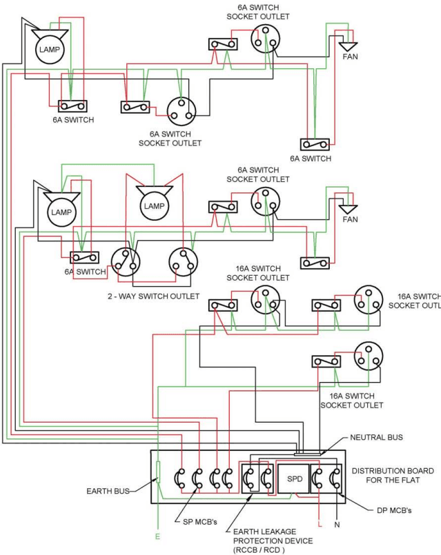
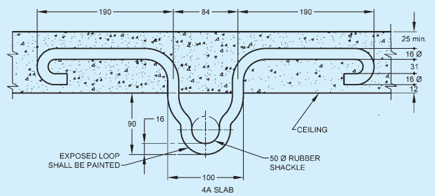
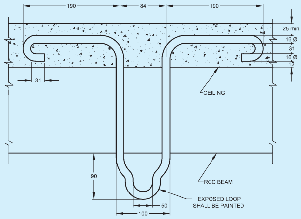
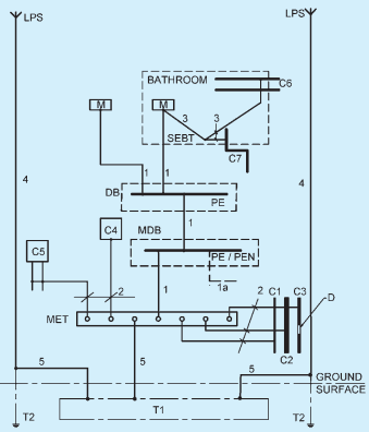
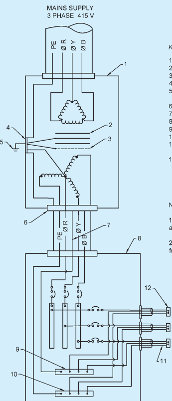
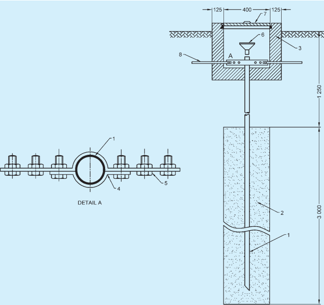
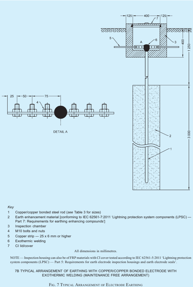
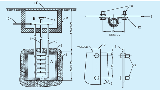
2.1 For the purpose of this Section, the following definitions shall apply. For definition of other terms, reference may be made to accepted standards [8-2(1)].
2.1.1 Accessory — A device, other than current using equipment, associated with such equipment or with the wiring of an installation.
2.1.2 Apparatus — Electrical apparatus including all machines, appliances and fittings in which conductors are used or of which they form a part.
2.1.3 Appliance — An item of current using equipment other than a luminaire or an independent motor.
2.1.4 Back-up Protection — Protection which is intended to operate when a system fault is not cleared or abnormal condition not detected in the required time, because of failure or inability of other protection to operate or failure of appropriate circuit-breaker to trip.
2.1.5 Barrier — A part providing a defined degree of protection against contact with live parts, from any usual direction of access.
2.1.6 Basic Protection — Protection against electric shock under fault-free condition.
NOTE — For low voltage installations, systems and equipment, basic protection generally corresponds to protection against direct contact that is ‘contact of persons or live parts’.
2.1.7 Bonding Conductor — A protective conductor providing equipotential bonding.
2.1.8 Bonding Ring Conductor (BRC) — A bus earthing conductor in the form of a closed ring.
NOTE — Normally the bonding ring conductor, as part of the bonding network, has multiple connections to the common bonding network (CBN) that improves its performance.
2.1.9 Bunched — Cables are said to be ‘bunched’ when two or more are contained within a single conduit, duct, ducting, or trunking, or, if not enclosed, are not separated from each other.
2.1.10 Buried Direct — A cable laid in the ground in intimate contact with the soil.
2.1.11 Busbar Trunking System — A type-tested assembly, in the form of an enclosed conductor system comprising solid conductors separated by insulating materials. The assembly may consist of units such as:
a) Busbur trunking units, with or without tap-off facilities;
b) Tap-off units where applicable; and
c) Phase-transposition, expansion, building-movement, flexible, end-feeder and adaptor units.
2.1.12 Bypass Equipotential Bonding Conductor — Bonding conductor connected in parallel with the screens of cables.
2.1.13 Cable — A length of single-insulated conductor (solid or stranded), or two or more such conductors, each provided with its own insulation, which are laid up together. The insulated conductor or conductors may or may not be provided with an overall mechanical protective covering.
2.1.14 Cable, Circuit Integrity — A cable which continues to function, that is, maintains the continuity of the circuit under circumstances of fire (against a specified temperature and period of the test).
NOTE — For circuit integrity cable requirements reference may be made to accepted standard [8-2(2)] , which prescribes a fire survival test at 750° C for 3 h.
2.1.15 Cable, Flame Retardant (FR) — A cable which is flame retardant as per the accepted standard [8-2(3)].
2.1.16 Cable, Flame Retardant Low Smoke and Halogen (FR-LSH) — A cable which is flame retardant and emits low smoke and halogen as per the accepted standard [8-2(3)].
2.1.17 Cable, Flexible — A cable containing one or more cores, each formed of a group of wires, the diameters of the cores and of the wires being sufficiently small to afford flexibility.
2.1.18 Cable, Metal-Sheathed — An insulated cable with a metal sheath.
2.1.19 Cable, PVC Sheathed-Insulated — A cable in which the insulation of the conductor is a polyvinylchloride (PVC) compound; with PVC sheath also providing mechanical protection to the conductor core or cores in the cable.
2.1.20 Cable, Weatherproof — A cable so constructed that when installed in uncovered locations, it will withstand all kinds of weather variations (see 2.1.186 for definition of weatherproof).
2.1.21 Cable, XLPE — A cable in which the insulation of the conductor is cross-linked polythene and the mechanical protection is provided for the core or cores by a sheath of a polyvinyl chloride compound.
2.1.22 Cable Armoured — A cable provided with a wrapping of metal (usually in the form of tape or wire) serving as a mechanical protection.
2.1.23 Cable Bracket — A cable support consisting of single devices fixed to elements of building or plant construction.
2.1.24 Cable Channel — An enclosure situated above or in the ground, open or ventilated or closed, and having dimensions which do not permit the access of persons but allow access to the conductor and/or cables throughout their length during and after installation.
NOTE — A cable channel may or may not form part of the building construction.
2.1.25 Cable Cleat — A component of a support system which consists of elements spread at intervals along the length of the cable or conduits and which mechanically retains the cable or conduit.
2.1.26 Cable Coupler — A means enabling the connection, at will, of two flexible cables. It consists of a connector and a plug.
2.1.27 Cable Ducting — A manufactured enclosure of metal or insulating material, other than conduit or cable trunking, intended for the protection of cables which are drawn-in after erection of the ducting, but which is not specifically intended to form part of a building structure.
2.1.28 Cable Ladder — A cable support occupying less than 10 percent of the plan area and consisting of a series of supporting elements rigidly fixed to each other or to a main supporting member or members.
2.1.29 Cable Raceways — An enclosed channel of metal or non-metallic materials designed expressly for holding wires, cables or busbars, with openable/maintainable construction having provision of ventilation. These include electrical non-metallic tubing, electrical metallic tubing, underfloor raceways, cellular concrete floor raceways, cellular metal floor raceways, surface raceways and wireways.
2.1.30 Cable Tray — A cable support consisting of a continuous base with raised edges and no covering. A cable tray is considered to be non-perforated, where less than 30 percent of the material is removed from the base.
2.1.31 Cable Trunking — A factory made closed support and protection system into which conductors and/or cables are laid after removal of the cover.
2.1.32 Cable Tunnel — An enclosure (corridor) containing supporting structures for conductors and/or cables and joints and whose dimensions allow free access to persons throughout the entire length.
2.1.33 Cartridge Fuse Link — A device comprising a fuse element or several fuse elements connected in parallel enclosed in a cartridge usually filled with an arc-extinguishing medium and connected to terminations. The fuse link is the part of a fuse which requires replacing after the fuse has operated.
2.1.34 Ceiling Rose — A fitting (usually used to attach to the ceiling) designed for the connection between the electrical installation wiring and a flexible cord (which is in turn connected to a lampholder).
2.1.35 Circuit — An assembly of electrical equipment supplied from the same origin and protected against overcurrent by the same protective device(s). Circuits are categorized as follows:
a) Category 1 circuit — A circuit (other than a fire alarm annunciation or emergency lighting circuit and other circuits required to work during fire in a building) operating at low voltage and supplied directly from a mains supply system.
b) Category 2 circuit — With the exception of Category 3 circuits, any circuit for extra low-voltage (ELV)/telecommunication [for example, radio, telephone, sound distribution, building management system (BMS), public address system (PAS), intruder alarm, bell and call and data transmission circuits)] which is supplied from a safety source.
c) Category 3 circuit — A fire alarm circuit or an emergency lighting circuit and other circuits required to work during fire in a building.
2.1.36 Circuit Breaker — A mechanical switching device, capable of making, carrying and breaking currents under normal circuit conditions and also of making, carrying for a specified time, and breaking currents under specified abnormal circuit conditions such as those of short circuit.
NOTE — A circuit breaker is usually intended to operate infrequently, although some types are suitable for frequent operation.
2.1.36.1 Miniature circuit breaker (MCB) — A compact mechanical switching device capable of making, carrying and breaking currents under normal circuit conditions and also making and carrying currents for specified times and automatically breaking currents
under specified abnormal circuit conditions, such as those of overload and short circuits.
2.1.36.2 Circuit breaker, linked — A circuit breaker, the contacts of which are so arranged as to make or break all poles simultaneously or in a definite sequence.
2.1.36.3 Moulded case circuit breaker (MCCB) — A circuit breaker having a supporting housing of moulded insulating material forming an integral part of the circuit breaker.
2.1.36.4 Air circuit breaker (ACB) — A circuit breaker in which the contacts open and close in air at atmospheric pressure.
2.1.36.5 Residual current operated circuit breaker — A mechanical switching device designed to make, carry and break currents under normal service conditions and to cause the opening of the contacts when the residual current attains a given value under specified conditions.
2.1.36.5.1 Residual current operated circuit breaker with integral overcurrent protection (RCBO) — A residual current operated circuit breaker designed to perform the functions of protection against overload and/or short-circuit.
2.1.36.5.2 Residual current operated circuit breaker without integral overcurrent protection (RCCB) — A residual current operated circuit breaker not designed to perform the functions of protection against overload and/or short-circuits.
NOTE — Similar function is provided by earth leakage circuit breaker (ELCB).
2.1.37 Circuit, Final Sub — An outgoing circuit connected to one-way distribution board and intended to supply electrical energy at one or more points to current, using appliances without the intervention of a further distribution board other than a one-way board. It includes all branches and extensions derived from that particular way in the board.
2.1.38 Circuit Integrity Cable Support and Fixing Materials — Supports and fixing materials for supporting circuit integrity cable (see 2.1.14), which continues in service after exposure to fire for a specified duration.
2.1.39 Compact Substation or Prefabricated Substation — Prefabricated and type-tested assembly which can be operated from inside (walk-in type) or outside (non-walk-in type) comprising components such as power transformer, high-voltage switchgear and controlgear, low-voltage switchgear and controlgear, corresponding interconnections (cable, busbar or other) and auxiliary equipment and circuits located next to each other, maintaining segregation and integrity of each compartment in which they are located along with
external interconnecting cables, earthing, protections, etc. The components shall be enclosed, by either a common enclosure or by an assembly of enclosures.
NOTE — See accepted standard [8-2(4)] for requirements of prefabricated substation.
2.1.40 Conductor of a Cable or Core — The conducting portion consisting of a single wire or group of wires, assembled together and in contact with each other or connected in parallel.
2.1.41 Conductor, Aerial — Any conductor which is supported by insulators above the ground and is directly exposed to the weather.
NOTE — Following four classes of aerial conductors are recognized:
a) Bare aerial conductors,
b) Covered aerial conductors,
c) Insulated aerial conductors, and
d) Weatherproof neutral-screened cable.
2.1.42 Conductor, Bare — A conductor not covered with insulating material.
2.1.43 Conductor, Earthed — A conductor with no provision for its insulation from earth.
2.1.44 Conductor, Insulated — A conductor adequately covered with insulating material of such quality and thickness as to prevent danger.
2.1.45 Conduit — A part of a closed wiring system, a circular or non-circular cross-section for conductors and/or cables in electrical installations, allowing them to be drawn in and/or replaced. Conduits should be sufficiently closed-jointed so that the conductors can only be drawn in and not inserted laterally.
2.1.46 Connector — The part of a cable coupler or of an appliance coupler which is provided with female contact and is intended to be attached to the flexible cable connected to the supply.
2.1.47 Connector Box or Joint Box — A box forming a part of wiring installation, provided to contain joints in the conductors of cables of the installations.
2.1.48 Connector for Portable Appliances — A combination of a plug and socket arranged for attachment to a portable electrical appliance or to a flexible cord.
2.1.49 Consumer's Terminals — The ends of the electrical conductors situated upon any consumer's premises and belonging to him, at which the supply of energy is delivered from the service line.
2.1.50 Continuous Operating Voltage (Uc) — Maximum rms voltage which may be continuously applied to a surge protection device's mode of protection. This is equal to rated voltage.
2.1.51 Cord, Flexible — A flexible cable having a large number of (typically 16 or 23 or 46 or 89, etc) strands of conductors of small cross-sectional area. Two flexible cords twisted together are known as twin ‘flexible cord’.
NOTE — Large number of fine strands of wires for each conductor makes the conductor capable of withstanding frequent bends thereby improving their flexibility.
2.1.52 Core of a Cable — A single conductor of a cable with its insulation but not including any mechanical protective covering.
2.1.53 Current Carrying Capacity of a Conductor — The maximum current which can be carried by a conductor under specified conditions without its steady state temperature exceeding a specified value.
2.1.54 Current Using Equipment — Equipment which converts electrical energy in to another form of energy, such as light, heat, or motive power.
2.1.55 Cut-out — Any appliance for automatically interrupting the transmission of energy through any conductor when the current rises above a predetermined amount.
2.1.56 Damp Situation — A situation in which moisture is either permanently present or intermittently present to such an extent as likely to impair the effectiveness of an installation conforming to the requirements for ordinary situations.
2.1.57 Danger — Danger to health or danger to life or limb from shock, burn or injury from mechanical movement to persons (and livestock where present), or from fire attendant upon the use of electrical energy.
2.1.58 Dead — A portion of an electrical circuit (normally expected to carry a voltage) at or near earth potential or apparently disconnected from any live system. A circuit apparently disconnected from all sources is expected to be at earth potential; but capacitive storage of charge in cables, capacitors, etc, can keep the electric circuit at a significant voltage (and often dangerous voltages from aspects of shock). Such circuits with storage components will be dead only on connection to earth.
2.1.59 Design Current (of a Circuit) — The magnitude of the current intended to be carried by the circuit in normal service.
2.1.60 Direct Contact — Contact of persons or live stock with live parts which may result in electric shock.
2.1.61 Direct Earthing System — A system of earthing in which the parts of an installation are so earthed as specified, but are not connected within the installation
to the neutral conductor of the supply system or to earth through the trip coil of an earth leakage circuit-breaker.
2.1.62 Disconnector — A mechanical switching device which, in the open position, complies with the requirements specified for the isolation function.
NOTES
1 A disconnector is otherwise known as isolator.
2 A disconnector is capable of opening and closing a circuit when either a negligible current is broken or made, or when no significant change in the voltage across the terminals of each pole of the disconnector occurs. It is also capable of carrying currents under normal circuit conditions and carrying for a specified time, current under abnormal conditions, such as those of short-circuit.
2.1.63 Discrimination (Over-Current Discrimination) — Coordination of the operating characteristics of two or more over-current protective devices should be such that, on the incidence of over-currents within stated limits, the device intended to operate would be the device closest to the point of fault or abnormality, and if proper discrimination is achieved within these limits, only that device closest should operate, while the other circuit breakers upstream do not operate, thereby ensuring that there is minimum area of power supply which is interrupted.
1 Protective devices should have discrimination so that only the affected part (minimum section) of the circuit is isolated, even though a number of protective devices may be in the path of the over current.
2 The electrical network requires the discrimination for all the fault circuits, including overload, short-circuit, etc. The downstream device should take care of the fault up to the level of ultimate short-circuit breaking capacity, Icu of the downstream breaker which should be equal to the bus which is connected.
3 Distinction is made between series discrimination involving different over-current protective devices passing substantially the same over-current and network discrimination involving identical protective devices passing different proportions of the over-current.
4 Different types of protective devices may have to be used to ensure effective discrimination in circuits where proper and effective discrimination is necessary. Apart from the built-in sensors and actuators in circuit breakers, external relays operating on different parameters, and comparison of parameters between two or more points will have to be used for complex installations.
5 See also relevant parts of the accepted standard [8-2(5)].
2.1.64 Distance Area or Resistance Area (for an Earth Electrode Only) — The surface area of ground (around an earth electrode) on which a significant voltage gradient may exist.
2.1.65 Diversity Factor — A measure of the probability that a particular piece of equipment will turn on coincidentally to another piece of equipment. For aggregate systems it is defined as the ratio of the sum of the individual non-coincident maximum loads of
various subdivisions of the system to the maximum demand of the complete system.
2.1.66 Duct — A closed passage way formed underground or in a structure and intended to receive one or more cables which may be drawn in.
2.1.67 Ducting — See 2.1.27.
2.1.68 Earth — The conductive mass of the earth, whose electric potential at any point is conventionally taken as zero.
2.1.69 Earth Continuity Conductor — The conductor, including any clamp, connecting to the earthing lead or to each other, those parts of an installation which are required to be earthed. It may be in whole or in part, the metal conduit or the metal sheath or armour of the cables, or the special continuity conductor of a cable or flexible cord incorporating such a conductor.
2.1.70 Earthed Concentric Wiring — A wiring system in which one or more insulated conductors are completely surrounded throughout their length by a conductor, for example a sheath, which acts as a PEN conductor.
2.1.71 Earth Electrode — A conductor or group of conductors in intimate contact with the ground to provide a low resistance path for flow of current to earth.
2.1.72 Earth Electrode Network — Part of an earthing arrangement comprising only the earth electrodes and their interconnections.
2.1.73 Earth Electrode Resistance — The resistance of an earth electrode to earth.
2.1.74 Earth Fault — An unintended and undesirable connection of phase/neutral conductor to earth. When the impedance is negligible, the connection is called a dead earth fault.
2.1.75 Earth Fault Current — A current resulting from a fault of negligible impedance between a line conductor and an exposed conductive part or a protective conductor.
2.1.76 Earthing — Connection of the exposed conductive parts of an installation to the main earthing terminal of that installation.
2.1.77 Earthing Conductor — A protective conductor connecting the main earth terminal (or equipotential bonding conductor of an installation when there is no earth bus) to an earth electrode or to other means of earthing.
2.1.78 Earthing Lead — The final conductor by which the connection to the earth electrode is made.
2.1.79 Earth Leakage Current — A current which flows to earth, or to extraneous conductive parts, in a circuit which is electrically sound.
NOTE — This current may have a capacitive component including that resulting from the deliberate use of capacitors.
2.1.80 Earthing Resistance, Total — The resistance between the main earthing terminal and the earth.
2.1.81 Electrical Equipment (abb: Equipment) — Any item for such purposes as generation, conversion, transmission, distribution or utilization of electrical energy, such as machines, transformers, apparatus, measuring instruments, protective devices, wiring materials, accessories, and appliances.
2.1.82 Electrically Independent Earth Electrodes — Earth electrodes located at such a distance from one another that the maximum current likely to flow through one of them does not significantly affect the potential of the other(s).
2.1.83 Electrical Supply System for Life and Safety Services — A supply system intended to maintain the operation of essential parts of an electrical installation and equipment,
a) for health and safety of persons and livestock; and
b) to avoid damage to the environment and to other equipment.
NOTES
1 The supply system includes the source and the circuit(s) up to the terminals of the electrical equipment.
2 See also Part 4 ‘Fire and Life Safety’ of the Code regarding emergency fire and life safety services.
2.1.84 Electric Shock — A dangerous pathophysiological effect resulting from the passing of an electric current through a human body or an animal.
2.1.85 Emergency Switching — Rapid cutting off of electrical energy to remove any hazard to persons, livestock, or property which may occur unexpectedly.
2.1.86 Enclosed Distribution Board — An enclosure containing bus bars with one or more control and protected devices for the purpose of protecting, controlling or connecting more than one outgoing circuits fed from one or more incoming circuits.
2.1.87 Enclosure — A part providing protection of equipment against certain external influences and, in any direction, protection against direct contact.
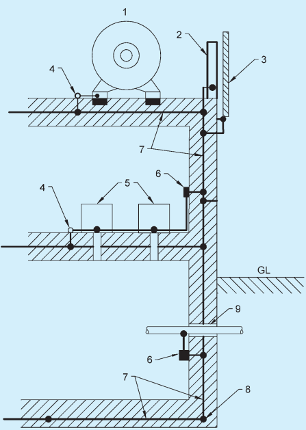
2.1.88 Equipotential Bonding — Electrical connection putting various exposed conductive parts and extraneous conductive parts at a substantially equal potential.
NOTE — In a building installation equipotential bonding conductors shall interconnect the following conductive parts:
a) Protective conductor,
b) Earth continuity conductor, and
c) Risers of air conditioning system and heating systems (if any).
2.1.89 Exposed Conductive Part — A conductive part of electrical equipment, which can be touched and which is not normally live, but which may become live under fault conditions.
2.1.90 Exposed Metal — All metal parts of an installation which are easily accessible other than,
a) parts separated from live parts by double insulation;
b) metal name-plates, screw heads, covers, or plates, which are supported on, or attached, or connected to substantial non-conducting material only in such a manner that they do not become alive in the event of failure of insulation of live parts and whose means of fixing do not come in contact with any internal metal; and
c) parts which are separated from live parts by other metal parts which are themselves earthed or have double insulation.
2.1.91 External Influence — Any influence external to an electrical installation which affects the design and safe operation of that installation.
2.1.92 Extraneous Conductive Part — A conductive part not forming part of the electrical installation and liable to introduce a potential, generally the earth potential.
2.1.93 Fault — A circuit condition in which current flows through an abnormal or unintended path. This may result from an insulation failure or a bridging of insulation. Conventionally the impedance between live conductors or between lives conductors and exposed or extraneous conductive parts at the fault position is considered negligible.
2.1.94 Fault Current — A current resulting from a fault.
2.1.95 Fault Protection — Protection against electric shock under single fault conditions.
NOTE — For low voltage installation, system’s and equipment’s fault protection generally corresponds to protection against indirect contact, mainly with regards to failure of basic insulation. Indirect contact is ‘contact of persons or livestock with exposed-conductive parts which have become live under fault conditions’.
2.1.96 Final Circuit — A circuit connected directly to current using equipment, or to socket outlets or other outlet points for the connection of such equipment.
2.1.97 Fire Survival Distribution Board — A distribution board which continues in service after exposure to fire to the required system rating.
2.1.98 Fitting, Lighting — A device for supporting or containing a lamp or lamps [for example, fluorescent or incandescent or halogen or compact fluorescent lamp (CFL) or light emitting diode (LED)] together with any holder, shade, or reflector, for example, a bracket, a pendant with ceiling rose, an electrolyer, or a portable unit.
2.1.99 Fixed Equipment — Equipment fastened to a support or otherwise secured.
2.1.100 Flameproof Enclosure — An enclosure which will withstand without injury any explosion of inflammable gas that may occur within it under practical conditions of operation within the rating of the apparatus (and recognized overloads, if any, associated therewith) and will prevent the transmission of flame which may ignite any inflammable gas that may be present in the surrounding atmosphere.
1 Hazardous areas are classified into different zones, depending upon the extent to which an explosive atmosphere may exist at that place. In such areas, flame proof switchgear, fittings, accessories, have to be used/installed in flameproof enclosure.
2 An electrical apparatus is not considered as flameproof unless it complies with the appropriate statutory regulations.
3 Other types of fittings are also in vogue in wiring installations, for example, ‘increased safety’.
2.1.101 Functional Earthing — Connection to earth necessary for proper functioning of electrical equipment.
2.1.102 Fuse — A device which, by melting of one or more of its specially designed and proportioned components, opens the circuit in which it is inserted by breaking the current when this exceeds a given value for a sufficient time. The fuse comprises all the parts that form the complete device.
2.1.103 Fuse Carrier — The movable part of a fuse designed to carry a fuse link.
2.1.104 Fuse Element — A part of a fuse designed to melt when the fuse operates.
2.1.105 Fuse Link — A part of fuse, including the fuse element(s), which requires replacement by a new or renewable fuse link after the fuse has operated and before the fuse is put back into service.
2.1.106 Hand-Held Equipment — Portable equipment intended to be held in the hand during normal use, in which the motor, if any, forms an integral part of the equipment.
NOTE — A hand held equipment is an item of equipment, the functioning of which requires constant manual support or guidance.
2.1.107 Harmonics (Current and Voltage) — All alternating current which is not absolutely sinusoidal is made up of a fundamental and a certain number of current and voltage harmonics [multiples of 50 Hz (basic frequency)] which are the cause of its deformation (distortion) when compared to the theoretical sine-wave.
2.1.108 Hazardous Live Part — A live part which can give, under certain condition of external influence, an electric shock.
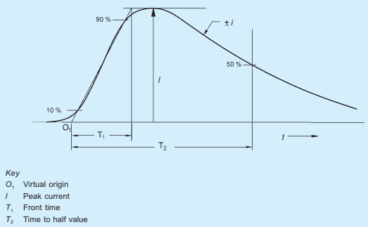
2.1.109 Impulse Current — A parameter used for the classification test for SPDs; it is defined by three elements, a current peak value, a charge Q and a specific energy W/R.
2.1.110 Impulse Withstand Voltage — The highest peak value of impulse voltage of prescribed form and polarity which does not cause breakdown of insulation under specified condition.
2.1.111 Indirect Contact — Contact of persons or livestock with exposed conductive parts made live by a fault and which may result in electric shock.
2.1.112 Industrial Plugs and Sockets — Plugs and socket-outlets, cable couplers and appliance couplers, primarily intended for industrial use, either indoors or outdoors.
NOTE — For the purpose of this Code, industrial plugs and sockets conforming to lS/IEC 60309-1:2002 ‘Plugs, socket-outlets and couplers for industrial purposes — Part 1: General requirements’; and lS/IEC 60309-2:2002 ‘Plugs, socket-outlets and couplers for industrial purposes — Part 2: Dimensional Interchangeability Requirements for Pin and Contact Tube Accessories’ shall be used for industrial purpose.
2.1.113 Inflammable Material — A material capable of being easily ignited.
2.1.114 Installation (Electrical) — An assembly of associated electrical equipment to fulfill a specific purpose or purposes and having coordinated characteristics.
2.1.115 Insulated — Insulated shall mean separated from adjacent conducting material or protected from personal contact by a non-conducting substance or an air space, in either case offering permanently sufficient resistance to the passage of current or to disruptive discharges through or over the surface of the substance or space, to obviate danger or shock or injurious leakage of current.
2.1.116 Insulation — Suitable non-conducting material, enclosing, surrounding or supporting a conductor.
2.1.116.1 Insulation, basic — Insulation applied to live parts to provide basic protection against electric shock and which does not necessarily include insulation used exclusively for functional purposes.
2.1.116.2 Insulation, double — Insulation comprising both basic and supplementary insulation.
NOTE — Double insulation for small hand held equipment allows them to be used without a safety earth connection, without shock risk such hand held equipment.
2.1.116.3 Insulation, reinforced — Single insulation applied to live parts, which provides a degree of protection against electric shock equivalent to double insulation under the conditions specified in the relevant standard.
NOTE — The term ‘single insulation’ does not imply that the insulation is a homogeneous piece. It may comprise several layers which cannot be tested singly as supplementary or basic insulation.
2.1.116.4 Insulation, supplementary — Independent insulation applied in addition to basic insulation in order to provide protection against electric shock in the event of a failure of basic insulation.
2.1.117 Isolation — Cutting off an electrical installation, a circuit, or an item of equipment from every source of electrical energy.
2.1.118 Isolator — A mechanical switching device which, in the open position, complies with the requirements specified for the isolating function. An isolator is otherwise known as a disconnector.
2.1.119 Junction Box — A box forming a part of wiring installation, intended to conceal electrical connections and joints of conductors/ cables in order to protect the connection from external influences such as direct contact, dust, water, moisture, UV radiation, etc, depending upon the protection requirement of the space or utility.
2.1.120 LEMP Protection Measures (SPM) — Measures taken to protect internal systems against the effects of LEMP.
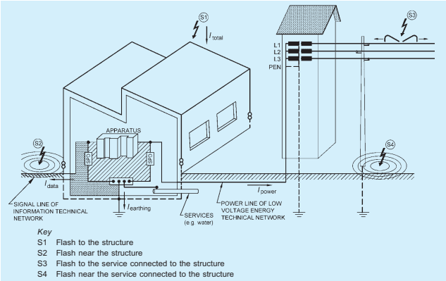
2.1.121 Lightning Electromagnetic Impulse (LEMP) — All electromagnetic effects of lightning current via resistive, inductive and capacitive coupling that create surges and radiated electromagnetic fields.
2.1.122 Lightning Protection — Complete system for protection of structures against lightning, including their internal systems and contents, as well as persons, in general consisting of an LPS and SPM.
2.1.123 Lightning Protection Level (LPL) — A number related to a set of lightning current parameters values relevant to the probability that the associated maximum and minimum design values will not be exceeded in naturally occurring lightning.
NOTE — Lightning protection level is used to design protection measures according to the relevant set of lightning current parameters.
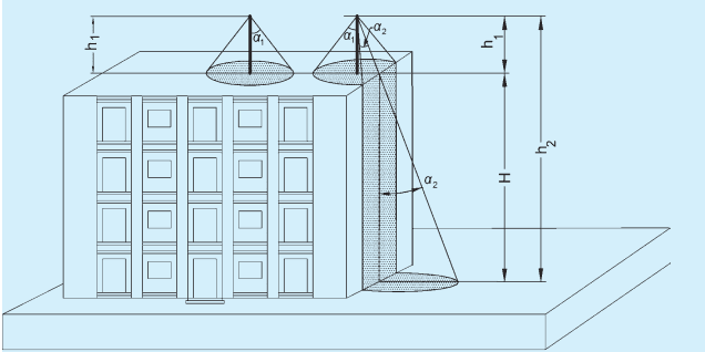
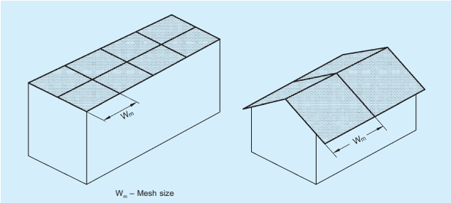
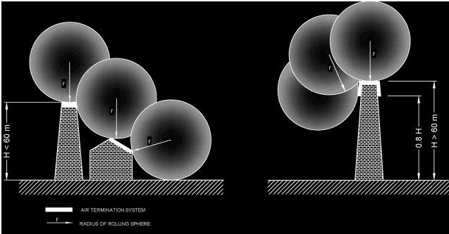
2.1.124 Lightning Protection System (LPS) — Complete system used to reduce physical damage due to lightning flashes to a structure.
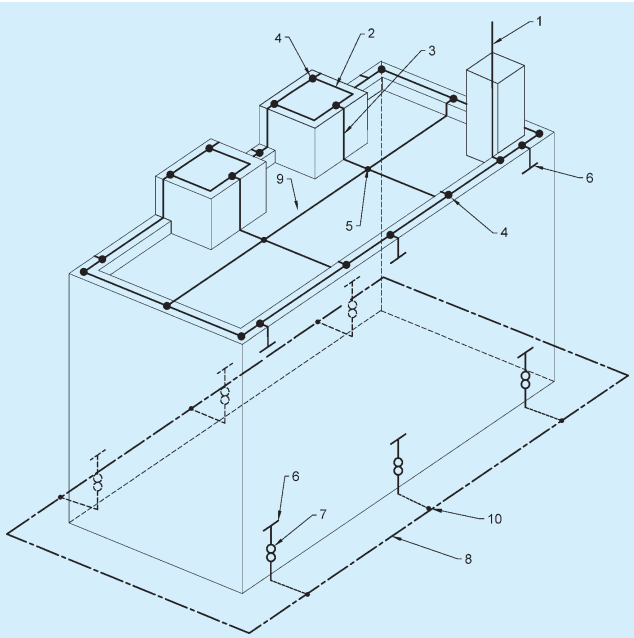
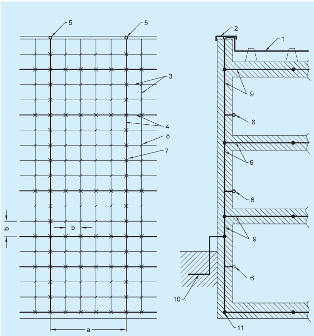
2.1.124.1 External lightning protection system — Part of the LPS consisting of an air-termination system, a down-conductor system and an earth-termination system.
2.1.124.2 Internal lightning protection system — Part of the LPS consisting of lightning equipotential bonding and/or electrical insulation of external LPS.
2.1.125 Lightning Protection Zone — Zone where the lightning electromagnetic environment is defined.
2.1.126 Live or Alive — Electrically charged so as to have a potential different from that of earth.
2.1.127 Locations, Industrial — Locations where tools and machinery requiring electrical wiring are installed for manufacture or repair.
2.1.128 Locations, Non-Industrial — Locations other than industrial locations, and shall include residences, offices, shops, showrooms, stores and similar premises requiring electrical wiring for lighting, or similar purposes.
2.1.129 Leakage Current — Electric current in an unwanted conductive path under normal operating conditions.
2.1.130 Line Conductor — A conductor of an a.c. system for the transmission of electrical energy other than a neutral conductor or a PEN conductor. This also means the equivalent conductor of a d.c. system unless otherwise specified in this Code.
2.1.131 Live Part — A conductor or conductive part intended to be energised in normal use including a neutral conductor but, by convention, not a PEN conductor.
2.1.132 Low Voltage Switchgear and Controlgear Assembly — A combination of one or more low voltage switching devices together with associated control, measuring, signalling, protective, regulating equipment, etc, completely assembled under the responsibility of the manufacturer with all the internal electrical and mechanical interconnections and structural parts. The components of the assembly may be electromechanical or electronic.
2.1.133 Luminaire — Equipment which distributes, filters or transforms the light from one or more lamps, and which includes any parts necessary for supporting, fixing and protecting the lamps, but not the lamps themselves, and, where necessary, circuit auxiliaries together with the means for connecting them to the supply.
NOTE — For the purposes of this Code a batten lampholder, or a lampholder suspended by flexible cord, is a luminaire.
2.1.134 Main Earthing Terminal — The terminal or bar which is the equipotential bonding conductor of protective conductors, and conductors for functional earthing, if any, to the means of earthing.
2.1.135 Meshed Bonding Network (MESH-BN) — Bonding network in which all associated equipment frames, racks and cabinets and usually the d.c. power return conductor are bonded together as well as at multiple points to the CBN and may have the form of a mesh.
2.1.136 Mobile Equipment — Electrical equipment which is moved while in operation or which can be easily moved from one place to another while connected to the supply.
2.1.137 Monitoring — Observation of the operation of a system or part of a system to verify correct functioning or detect incorrect functioning by measuring system variables and comparing the measured value with the specified value.
2.1.138 Multiple Earthed Neutral System — A system of earthing in which the parts of an installation specified to be earthed are connected to the general mass of earth and, in addition, are connected within the installation to the neutral conductor of the supply system.
2.1.139 Neutral Conductor — Includes the conductor of a three-phase four-wire system; the conductor of a single-phase or d.c. installation, which is earthed by the supply undertaking (or otherwise at the source of the supply), and the middle wire or common return conductor of a three-wire d.c. or single-phase a.c. system.
2.1.140 Origin of an Electrical Installation — The point at which electrical energy is delivered to an installation.
NOTE — An electrical installation may have more than one origin.
2.1.141 Overcurrent — A current exceeding the rated value. For conductors the rated value is the current carrying capacity.
2.1.142 Overload Current (of a Circuit) — An overcurrent occurring in a circuit in the absence of an electrical fault.
2.1.143 PEN Conductor — A conductor combining the functions of both protective conductor and neutral conductor.
2.1.144 Phase Conductor — See 2.1.130.
2.1.145 Plug — A device, provided with contact pins, which is intended to be attached to a flexible cable,
and which can be engaged with a socket outlet or with a connector.
2.1.146 Point (in Wiring) — A termination of the fixed wiring intended for the connection of current using equipment.
2.1.147 Portable Equipment — Equipment which is moved while in operation or which can easily be moved from one place to another while connected to the supply.
2.1.148 Protection, Ingress — The degree of protection against intrusions (body parts such as hands and fingers), dust, accidental contact and water.
NOTE — The classification of degrees of ingress protection provided by enclosures for electrical equipment shall be as per the accepted standard [8-2(6)].
2.1.149 Protection, Mechanical Impact — The degrees of protection provided by enclosures for electrical equipment against external mechanical impacts.
NOTE — The classification of degrees of protection against mechanical impact provided by enclosures for electrical equipment shall be as per IEC 62262:2002 ‘Degrees of protection provided by enclosures for electrical equipment against external mechanical impacts (IK code)’.
2.1.150 Prospective Fault Current ( Ipf ) — The value of overcurrent at a given point in a circuit resulting from a fault of negligible impedance between live conductor having a difference of potential under normal operating conditions, or between a live conductor and an exposed-conductive part.
2.1.151 Protective Conductor — A conductor used for some measures of protection against electric shock and intended for connecting together any of the following parts:
a) Exposed conductive parts,
b) Extraneous conductive parts,
c) Main earthing terminal, and
d) Earthed point of the source, or an artificial neutral.
2.1.152 Protective Conductor Current — Electric current appearing in a protective conductor, such as leakage current or electric current resulting from an insulation fault.
2.1.153 Protective Earthing — Earthing of a point or points in a system or in equivalent for the purpose of safety.
2.1.154 Protective Separation — Separation of one electric circuit from another by means of,
a) double insulation;
b) basic insulation and electrically protective screening (shielding); or
c) reinforced insulation.
2.1.155 Rated Current — Value of current used for specification purposes, established for a specified set of operating conditions of a component, device, equipment or system.
2.1.156 Rated Impulse Withstand Voltage Level ( Uw ) — The level of impulse withstand voltage assigned by the manufacturer to the equipment, or to part of it, characterizing the specified withstand capability of its insulation against overvoltage.
2.1.157 Residual Current — The algebraic sum of the instantaneous values of current flowing through all live conductors of a circuit at a point of the electrical installation.
2.1.158 Residual Current Device (RCD) — A mechanical switching device or association of devices intended to cause the opening of the contacts when the residual current attains a given value under specified conditions.
2.1.159 Residual Operating Current — Residual current which causes the residual current device to operate under specified conditions.
2.1.160 Service — The conductors and equipment required for delivering energy from the electric supply system to the wiring system of the premises served.
2.1.161 Shock Current A current passing through the body of a person or an animal and having characteristics likely to cause dangerous patho-physiological effects.
2.1.162 Short-Circuit Current — An overcurrent resulting from a fault of negligible impedance between live conductors having a difference in potential under normal operating conditions.
2.1.163 Space Factor — The ratio (expressed as a percentage) of the sum of the overall cross-sectional areas of cables (including insulation and sheath) to the internal cross-sectional area of the conduit or other cable enclosure in which they are installed. The effective overall cross-sectional area of a non-circular cable is taken as that of a circle of diameter equal to the major axis of the cable.
2.1.164 Standby Supply System — A system intended to maintain supply to the installation or part thereof, in case of interruption of the normal supply, for reasons other than safety of persons.
NOTE — Standby supplies are necessary, for example, to avoid interruption of continuous industrial processes or data processing.
2.1.165 Stationary Equipment — Either fixed equipment or equipment not provided with a carrying handle and having such a mass that it cannot easily be moved.
2.1.166 Step Voltage — The potential difference between two points on the earth's surface, separated by distance of one pace, that will be assumed to be one metre in the direction of maximum potential gradient.
2.1.167 Socket-Outlet — A device, provided with female contacts, which is intended to be installed with the fixed wiring, and intended to receive a plug.
NOTE — A luminaire track system is not regarded as a socket-outlet system.
2.1.168 Surge — A transient created by LEMP that appears as an overvoltage and/or an overcurrent.
2.1.169 Surge Protective Devices (SPD) — A device intended to limit transient overvoltages and divert surge currents. It contains at least one non-linear component.
2.1.170 Switch — A mechanical switching device capable of making, carrying and breaking current under normal circuit conditions, which may include specified operating overload conditions; and also of carrying for a specified time currents under specified abnormal circuit conditions, such as those of short circuit.
NOTE — A switch may also be capable of making, but not breaking, short-circuit currents.
2.1.171 Switchboard — An assembly of switchgear with or without instruments, but the term does not apply to a group of local switches in a final circuit.
NOTE — The term ‘switchboard’ includes a distribution board.
2.1.172 Switch Disconnector — A switch which, in the open position, satisfies the isolating requirements specified for a disconnector.
NOTE — A switch disconnector is otherwise known as an isolating switch.
2.1.173 Switch Disconnector Fuse — A composite unit, comprising a switch with the fuse contained in or mounted on the moving member of the switch.
2.1.174 Switch, Linked — A switch, the contacts of which are so arranged as to make or break all poles simultaneously or in a definite sequence.
2.1.175 Switchgear — An assembly of main and auxiliary switching apparatus for operation, regulation, protection or other control of electrical installations.
2.1.176 System (Electrial) — An electrical system consisting of a single source or multiple sources running in parallel of electrical energy and an installation. Types of system are identified as follows, depending upon the relationship of the source, and of exposed-conductive parts of the installation, to earth:
a) TN system — A system having one or more points of the source of energy directly earthed, the exposed conductive-parts of the installation being connected to that point by
protective conductors.
b) TN-C system — A system in which neutral and protective conductors are combined in a single conductor throughout the system.
c) TN-S system — A system having separate neutral and protective conductor throughout the system.
d) TN-C-S system — A system in which neutral and protective conductors are combined in a single conductor in part of the system.
e) TT system — A system having one point of the source of energy directly earthed, the exposed-conductive-parts of the installation being connected to the earth electrodes electrically independent of the earth electrodes of the source.
f) IT system — A system having no direct connection between live parts and earth, the exposed-conductive-parts of the electrical installation being earthed.
2.1.177 Touch Voltage — The potential difference between the ground potential rise (GPR) of a grounded metallic structure and the surface potential at the point where a person could be standing while at the same time having a hand in contact with the grounded metallic structure. Touch voltage measurements can be ‘open circuit’ (without the equivalent body resistance included in the measurement circuit) or ‘closed circuit’ (with the equivalent body resistance included in the measurement circuit) voltage by which an installation or part of an installation is designated.
2.1.178 Usable Wall Space — All portions of a wall, except that occupied by a door in its normal open position, or occupied by a fire place opening, but excluding wall spaces which are less than 1 m in extent measured along the wall at the floor line.
2.1.179 Utility Building — A standalone separate single or two storied service building structure outside the main building structure meant for only accommodating services’ spaces, such as electric substation, diesel generator plant room, a.c. plant room, plumbing plant room, sewerage treatment plant, medical gases, electrical and mechanical maintenance rooms. Such buildings do not have any permanent occupancy other than by personnel on duty.
2.1.180 Voltage, Nominal (of an Installation) — Voltage by which an installation or part of an installation is designated.
2.1.181 Voltage, Extra Low (ELV) — The voltage which does not normally exceed 50 V.
2.1.182 Voltage, Low (LV) — The voltage which normally exceeds 50 V but does not normally exceed 250 V.
2.1.183 Voltage, Medium (MV) — The voltage which normally exceeds 250 V but does not exceed 650 V.
2.1.184 Voltage, High (HV) — The voltage which normally exceeds 650 V but less than or equal to 33 kV.
2.1.185 Voltage, Extra High (EHV) — The voltage, which normally exceeds 33 kV.
2.1.186 Weatherproof — Accessories, lighting fittings, current-using appliances and cables are said to be of the weatherproof type with ingress protection according to the application, if they are so constructed that when installed in open situation they will withstand the effects of rain, snow, dust and temperature variations.
2.2 Conventional Symbols
The architectural symbols that are to be used in all drawings, wiring plans, etc, for electrical installations in buildings shall be as given in Annex A.
For other graphical symbols used in electrotechnology, reference may be made to good practice [8-2(1)].