| bf | — | Width of the flange | Ftest, Min | — | Minimum test load from the test to failure |
| bi | — | Width of flange as an internal element | | | Minimum test load from the test to failure |
| bo | — | Width of flange outstand | Ftest, R | — | Test load resistance |
| bp | — | Panel zone width between column flanges at beam-column junction | Ftest, S | — | Strength test load |
| bp | — | Panel zone width between column flanges at beam-column junction | Fw | — | Design capacity of the web in bearing |
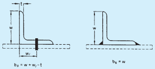
| bs | — | Shear lag distance | Fx | — | External load, force or reaction |
| bt | — | Width of tension field | Fxd | — | Buckling resistance of load carrying web stiffener |
| bw | — | Width of outstanding leg | | | Buckling resistance of load carrying web stiffener |
| C | — | Centre-to-centre longitudinal distance of battens | f | — | Actual normal stress range for the detail category |
| Cm | — | Coefficient of thermal expansion | f₁ | — | Frequency for a simply supported one way system |
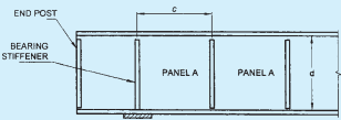
| c | — | Spacing of transverse stiffener | | | Frequency for a simply supported one way system |
| cb | — | Moment amplification factor for braced member | f₂ | — | Frequency of floor supported on steel girder perpendicular to the joist |
| cm | — | Moment reduction factor for lateral torsional buckling strength calculation | fa | — | Calculated stress due to axial force at service load |
| cm | — | Moment reduction factor for lateral torsional buckling strength calculation | fabc | — | Permissible bending stress in compression at service load |
| cs | — | Moment amplification factor for sway frame | fac | — | Permissible compressive stress at service load |
| D | — | Overall depth/diameter of the cross-section | fabt | — | Permissible bending stress in tension at service load |
| d | — | Depth of web, nominal diameter | | | Permissible bending stress in tension at service load |
| d₂ | — | Twice the clear distance from the compression flange angles, plates or tongue plates to the neutral axis | fapb | — | Permissible bearing stress of the bolt at service load |
| d₂ | — | Twice the clear distance from the compression flange angles, plates or tongue plates to the neutral axis | fasb | — | Permissible stress of the bolt in shear at service load |
| dh | — | Diameter of a bolt/ rivet hole | fat | — | Permissible tensile stress at service load |
| do | — | Nominal diameter of the pipe column or the dimensions of the column in the depth direction of the base plate | fatb | — | Permissible tensile stress of the bolt at service load |
| dp | — | Panel zone depth in the beam-column junction | faw | — | Permissible stress of the weld at service load |
| E | — | Modulus of elasticity for steel | | | Permissible stress of the weld at service load |
| E(T) | — | Modulus of elasticity of steel at T°C | fb | — | Actual bending stress at service load |
| E(20) | — | Modulus of elasticity of steel at 20°C | fbc | — | Actual bending stress in compression at service load |
| Ep | — | Modulus of elasticity of the panel material | fbd | — | Design bending compressive stress corresponding to lateral buckling |
| Fcdw | — | Buckling strength of un-stiffened beam web under concentrated load | fbr | — | Actual bearing stress due to bending at service load |
| Fd | — | Factored design load | fbt | — | Actual bending stress in tension at service load |
| Fn | — | Normal force | | | Actual bending stress in tension at service load |
| Fo | — | Minimum proof pretension in high strength friction grip bolts | fbs | — | Permissible bending stress in column base at service load |
| Fpsd | — | Bearing capacity of load carrying stiffener | fc | — | Actual axial compressive stress at service load |
| Fq | — | Stiffener force | fcc | — | Elastic buckling stress of a column, Euler buckling stress |
| Fqd | — | Stiffener buckling resistance | | | Elastic buckling stress of a column, Euler buckling stress |
| Ftest | — | Test load | fcd | — | Design compressive stress |
| Ftest,a | — | Load for acceptance test | fcr,b | — | Extreme fibre compressive stress |
| | corresponding to elastic lateral buckling moment | G | — | Modulus of rigidity for steel |
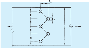
| | corresponding to elastic lateral buckling moment | g | — | Gauge length between centres of the holes perpendicular to the load direction, acceleration due to gravity |
| fe | — | Equivalent stress at service load | | | Gauge length between centres of the holes perpendicular to the load direction, acceleration due to gravity |
| ff | — | Fatigue stress range corresponding to 5 × 10⁶ cycles of loading | h | — | Depth of the section |
| ffeq | — | Equivalent constant amplitude stress | hb | — | Total height from the base to the floor level concerned |
| ffd | — | Design normal fatigue strength | | | Total height from the base to the floor level concerned |
| ff, Max | — | Highest normal stress range | hc | — | Height of the column |
| ffn | — | Normal fatigue stress range | he | — | Effective thickness |
| fnw | — | Normal stress in weld at service load | hf | — | Centre-to-centre distance of flanges |
| fo | — | Proof stress | hi | — | Thickness of fire protection material |
| fp | — | Actual bearing stress at service load | hL | — | Height of the lip |
| fpb | — | Actual bearing stress in bending at service load | hs | — | Storey height |
| | | hy | — | Distance between shear centre of the two flanges of a cross-section |
| fpsd | — | Bearing strength of the stiffeners | | | Distance between shear centre of the two flanges of a cross-section |
| fr | — | Frequency | I | — | Moment of inertia of the member about an axis perpendicular to the plane of the frame |
| fsb | — | Actual shear stress in bolt at service load | | | Moment of inertia of the member about an axis perpendicular to the plane of the frame |
| ft | — | Actual tensile stress at service load | Ifc | — | Moment of inertia of the compression flange of the beam about the axis parallel to the web |
| ftb | — | Actual tensile stress of the bolt at service load | | | Moment of inertia of the compression flange of the beam about the axis parallel to the web |
| fu | — | Characteristic ultimate tensile stress | Ift | — | Moment of inertia of the tension flange of the beam about minor axis |
| fub | — | Characteristic ultimate tensile stress of the bolt | Iq | — | Moment of inertia of a pair of stiffener about the centre of the web, or a single stiffener about the face of the web. |
| fum | — | Average ultimate stress of the material as obtained from test | | | Moment of inertia of a pair of stiffener about the centre of the web, or a single stiffener about the face of the web. |
| fup | — | Characteristic ultimate tensile stress of the connected plate | Is | — | Second moment of inertia |
| fv | — | Applied shear stress in the panel designed utilizing tension field action | Iso | — | Second moment of inertia of the stiffener about the face of the element perpendicular to the web |
| fw | — | Actual stress of weld at service load | IT | — | Transformed moment of inertia of the one way system (in terms of equivalent steel, assuming the concrete flange of width equal to the spacing of the beam to be effective) |
| fwd | — | Design stress of weld at service load | | | Transformed moment of inertia of the one way system (in terms of equivalent steel, assuming the concrete flange of width equal to the spacing of the beam to be effective) |
| fwn | — | Nominal strength of fillet weld | | | Transformed moment of inertia of the one way system (in terms of equivalent steel, assuming the concrete flange of width equal to the spacing of the beam to be effective) |
| fx | — | Maximum longitudinal stress under combined axial force and bending | It | — | St. Venant's torsion constant |
| fy | — | Characteristic yield stress | Iw | — | Warping constant |
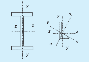
| fy(T) | — | Yield stress of steel at T°C | Iy | — | Moment of inertia about the minor axis of the cross-section |
| fy(20) | — | Yield stress of steel at 20°C | Iz | — | Moment of inertia about the major axis of the cross-section |
| fyb | — | Characteristic yield stress of bolt | | | Moment of inertia about the major axis of the cross-section |
| fyf | — | Characteristic yield stress of flange | Kb | — | Effective stiffness of the beam and column |
| fym | — | Average yield stress as obtained from test | Kh | — | Reduction factor to account for the high strength friction grip connection bolts in oversized and slotted holes |
| fyp | — | Characteristic yield stress of connected plate | | | Reduction factor to account for the high strength friction grip connection bolts in oversized and slotted holes |
| fyq | — | Characteristic yield stress of stiffener material | KL | — | Effective length of the member |
| fyw | — | Characteristic yield stress of the web material | KL/r | — | Appropriate effective slenderness ratio of the section |
| | | KL/ry | — | Effective slenderness ratio of the |
| | section about the minor axis of the section | M | — | Bending moment |
| KL/rz | — | Effective slenderness ratio of the section about the major axis of the section | Ma | — | Applied bending moment |
| KL/rz | — | Effective slenderness ratio of the section about the major axis of the section | Mcr | — | Elastic critical moment corresponding to lateral torsional buckling of the beam |
| ((KL)/(r))o | — | Actual maximum effective slenderness ratio of the laced column | Md | — | Design flexural strength |
| ((KL)/(r))o | — | Actual maximum effective slenderness ratio of the laced column | Mdv | — | Moment capacity of the section under high shear |
| ((KL)/(r))e | — | Effective slenderness ratio of the laced column accounting for shear deformation | Mdy | — | Design bending strength about the minor axis of the cross-section |
| ((KL)/(r))e | — | Effective slenderness ratio of the laced column accounting for shear deformation | Mdz | — | Design bending strength about the major axis of the cross-section |
| Kv | — | Shear buckling coefficient | Meff | — | Reduced effective moment |
| Kw | — | Warping restraint factor | Mfr | — | Reduced plastic moment capacity of the flange plate |
| k | — | Regression coefficient | | | |
| ksm | — | Exposed surface area to mass ratio | Mfd | — | Design plastic resistance of the flange alone |
| Ky, Kz, | — | Moment amplification factors (see 10.4.2, 10.4.3.1, 10.4.3.3 and 15.3.2.2) | Mnd | — | Design bending strength under combined axial force and uniaxial moment |
| KLT | | Moment amplification factors (see 10.4.2, 10.4.3.1, 10.4.3.3 and 15.3.2.2) | Mnd | — | Design bending strength under combined axial force and uniaxial moment |
| L | — | Actual length, unsupported length, length centre-to-centre distance of the intersecting members, cantilever length | Mndy, Mndz | — | Design bending strength under combined axial force and the respective uniaxial moment acting alone |
| Lc | — | Length of end connection in bolted and welded members, taken as the distance between outermost fasteners in the end connection, or the length of the end weld, measured along the length of the member | Mp | — | Plastic moment capacity of the section |
| Lc | — | Length of end connection in bolted and welded members, taken as the distance between outermost fasteners in the end connection, or the length of the end weld, measured along the length of the member | Mpb | — | Moment in the beam at the intersection of the beam and column centre lines |
| LLT | — | Effective length for lateral torsional buckling | Mpc | — | Moments in the column above and below the beam surfaces |
| Lm | — | Maximum distance from the restraint to the compression flange at the plastic hinge to an adjacent restraint (limiting distance) | Mpd | — | Plastic design strength |
| Lm | — | Maximum distance from the restraint to the compression flange at the plastic hinge to an adjacent restraint (limiting distance) | Mpdf | — | Plastic design strength of flanges only |
| Lm | — | Maximum distance from the restraint to the compression flange at the plastic hinge to an adjacent restraint (limiting distance) | Mq | — | Applied moment on the stiffener |
| Lo | — | Length between points of zero moment (inflection) in the span | Ms | — | Moment at service (working) load |
| Lo | — | Length between points of zero moment (inflection) in the span | Mtf | — | Moment resistance of tension flange |
| l | — | Centre-to-centre length of the supporting member | My | — | Factored applied moment about the minor axis of the cross-section |
| le | — | Distance between prying force and bolt centre line | Myq | — | Moment capacity of the stiffener based on its elastic modulus |
| lg | — | Grip length of bolts in a connection | Mz | — | Factored applied moment about the major axis of the cross-section |
| lj | — | Length of the joint | N | — | Number of parallel planes of battens |
| ls | — | Length between points of lateral support to the compression flange in a beam. | Nd | — | Design strength in tension or in compression |
| lv | — | Distance from bolt centre line to the toe of fillet weld or to half the root radius for a rolled section | Nf | — | Axial force in the flange |
| lv | — | Distance from bolt centre line to the toe of fillet weld or to half the root radius for a rolled section | NSC | — | Number of stress cycles |
| lv | — | Distance from bolt centre line to the toe of fillet weld or to half the root radius for a rolled section | n | — | Number of bolts in the bolt group/critical section |
| lw | — | Length of weld | | | |