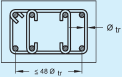
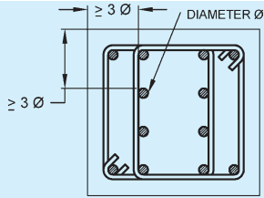
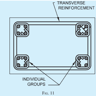
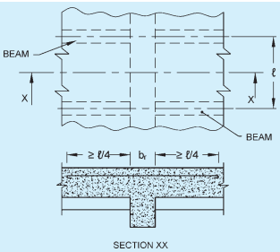
This Code (Part 6/Subsection 5A) covers the structural design aspects of plain and reinforced concrete.
The Section 5 of Part 6 of the Code covers plain and reinforced concrete and also the prestressed concrete. The Section has been subdivided into the following subsections:
5A Plain and Reinforced Concrete
5B Prestressed Concrete
This Subsection 5A was first published in 1970 as Subsection 5A of SP 7 (Part 6) and was subsequently revised in 1983 and 2005, to bring it in line with revised version of IS 456 : 1978 and IS 456 : 2000, respectively on which this chapter was based.
The second revision (NBC 2005) incorporated a number of important changes. The major thrust being:
a) In recent years, durability of concrete structures have become the cause of concern to all concrete technologists. This has led to codify the durability requirements world over. In this revision of the Code, in order to introduce in-built protection from factors affecting a structure, earlier clause on durability has been elaborated and a detailed clause covering different aspects of design of durable structure has been incorporated.
b) Sampling and acceptance criteria for concrete have been revised. With this revision acceptance criteria has been simplified in line with the provisions given in BS 5328 (Part 4): 1990 'Concrete: Part 4 Specification for the procedures to be used in sampling, testing and assessing compliance of concrete'.
Some of the significant changes incorporated in the 2005 version were: inclusion of all the three grades of ordinary Portland cement, namely 33 Grade, 43 Grade and 53 Grade and sulphate resisting Portland cement in the list of types of cement used (in addition to other types of cement); modification of the permissible limits for solids in water keeping in view the durability requirements; modification of the clause on admixtures in view of the availability of new types of admixtures including superplasticizers; inclusion of grades higher than M 40 in Table 2 'Grades of Concrete'; recommendations regarding minimum grade of concrete to be not less than M 20 in reinforced concrete work (see also 5.1.3); revision of the formula for estimation of modulus of elasticity of concrete; specification of workability only in terms of slump, in the absence of proper correlation between compacting factor, vee-bee time and slump, modification of the clause on 'Durability' to include detailed guidance concerning the factors affecting durability; modification of the table on 'Environmental Exposure Conditions' to include 'very severe' and 'extreme' exposure conditions, also covering requirements for shape and size of member, depth of concrete cover, concrete quality, requirement against exposure to aggressive chemical and sulphate attack, minimum cement requirement and maximum water cement ratio, limits of chloride content, alkali silica reaction, and importance of compaction, finishing and curing; incorporation of a clause on 'Quality Assurance Measures' to give due emphasis to good practices of concreting; introduction of proper limits on the accuracy of measuring equipments to ensure accurate batching of concrete; modification of the clause on 'Construction Joints'; and modification of the clause on 'Inspection' to give more emphasis on quality assurance.
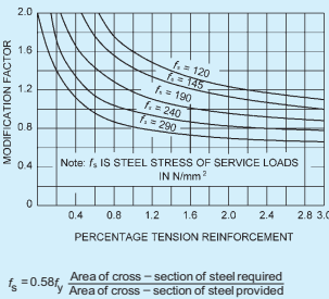
The significant changes incorporated in Section 5A (C) of the 2005 version were: detailing of requirements for ‘Fire Resistance’; modification of the figure for estimation of modification factor for tension reinforcement used in calculation of basic values of span to effective depth to control the deflection of flexural member; addition of recommendations regarding effective length of cantilever; addition of recommendations regarding deflection due to lateral loads; inclusion of recommendations for adjustments of support moments in restrained slabs; introduction of stability index in the determination of effective length of compression members, to determine sway or no sway conditions; inclusion of recommendations for lap length of hooks for bars in direct tension and flexural tension; modification of recommendations regarding strength of welds; modification in recommendations regarding cover to reinforcement; prescription of cover based on durability requirements for different exposure conditions; introduction of the term ‘nominal cover’; and prescription of the cover based on durability requirement as well as for fire requirements.
The significant change incorporated in Section 5A (D) of the 2005 version included modification of the clause on walls. The modified clause includes design of walls against horizontal shear.
In Section 5 of the 2005 version on limit state method, a new clause was added for calculation of enhanced shear strength of sections close to supports. Some modifications were also made in the clause on Torsion. Formula for calculation of crack width were added (separately in Annex F).
Working stress method was added in Annex A so as to give greater emphasis to limit state design. In this annex, modifications regarding torsion and enhanced shear strength on the same lines as in Section 5 have been made.
Whilst the common methods of design and construction have been covered in this code, special systems of design and construction of any plain or reinforced concrete structure not covered by this code may be permitted on production of satisfactory evidence regarding their adequacy and safety by analysis or test or both (see 18).
In this Code it has been assumed that the design of plain and reinforced cement concrete work is entrusted to a qualified engineer and that the execution of cement concrete work is carried out under the direction of a qualified and experience supervisor.
In this third revision of this Subsection, the following major modifications have been incorporated:
a) All the 4 amendments so far issued to IS 456 : 2000 ‘Code of practice for plain and reinforced concrete (fourth revision)’ have been incorporated.
b) Provisions relating to use of mineral admixtures, their effects on properties of fresh and hardened concrete have been elaborated, including precautions associated therewith.
c) Aggregates from other than natural sources, including iron slag aggregate, steel slag aggregate, copper slag aggregate, bottom ash from thermal power plant, and aggregate derived from construction and demolition waste, have been included through cross reference to the revised IS 383, namely IS 383 : 2016 ‘Specification for coarse and fine aggregate for concrete (third revision)’.
d) Provisions relating to stripping time of forms for beams and slabs have been modified, also emphasizing the need for immediate replacement of props have been included.
e) The stripping time in case of the concrete made using cement other than OPC or using cementitious materials like fly ash and slag, has been specified, also giving guidance on minimum cube strength requirements of concrete before removal of formwork in case provision of stripping time applicable for concrete made using OPC, is to be used.
f) Provisions related to self compacting concrete (SCC) and high performance concrete (HPC) have been included as part of special concretes.
g) Design provisions related to steel fibre reinforced concrete have been included as part of special concretes.
h) Provisions related to shear stress for coupled shear walls have been included.
j) Comprehensive provisions on ductile detailing have been included from IS 13920 : 2016 ‘Code of practice for ductile detailing of reinforced concrete structures subjected to seismic forces (first revision)’ to help extensive implementation of ductile detailing provisions in all relevant structures.
k) List of Indian Standards referred as good practice has been updated, especially in view of formulation of a number of new/revision of Indian Standards relating to concrete.
This Subsection is largely based on the following Indian Standards:
IS 456 : 2000 Code of practice for plain and reinforced concrete (fourth revision)
IS 13920 : 2016 Code of practice for ductile detailing of reinforced concrete structures subjected to seismic forces (first revision)
All standards, whether given herein above or cross-referred to in the main text of this Subsection, are subject to revision. The parties to agreement based on this Subsection are encouraged to investigate the possibility of applying the most recent editions of the standards.
For the purpose of deciding whether a particular requirement of this Subsection is complied with, the final value, observed or calculated, expressing the result of a test or analysis, shall be rounded off in accordance with IS 2 : 1960 ‘Rules for rounding off numerical values (revised)’. The number of significant places retained in the rounded off value should be the same as that of the specified value in this Subsection.
(a) General
3Symbols
For the purpose of this Subsection, the following letter symbols shall have the meaning indicated against each; where other symbols are used, they are explained at the appropriate place:
A — Area
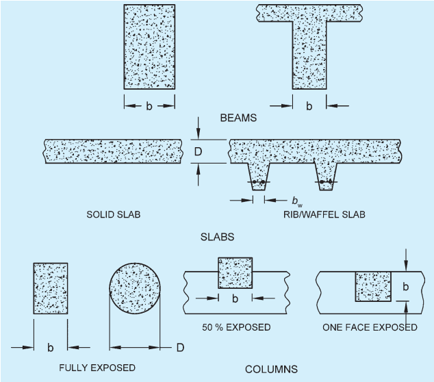
b — Breadth of beam, or shorter dimension of
a rectangular column
bef — Effective width of slab
bf — Effective width of flange
bw — Breadth of web or rib
D — Overall depth of beam or slab or diameter of column; dimension of a rectangular column in the direction under consideration
Df — Thickness of flange
DL — Dead load
d — Effective depth of beam or slab
d' — Depth of compression reinforcement from the highly compressed face
Ec — Modulus of elasticity of concrete
EL — Earthquake load
Es — Modulus of elasticity of steel
e — Eccentricity
fck — Characteristic cube compressive strength of concrete
fcr — Modulus of rupture of concrete (flexural tensile strength)
fct — Splitting tensile strength of concrete
fd — Design strength
fy — Characteristic strength of steel
Hw — Unsupported height of wall
Hwe — Effective height of wall
Ief — Effective moment of inertia
Igr — Moment of inertia of the gross section excluding reinforcement
Ir — Moment of inertia of cracked section
K — Stiffness of member
k — Constant or coefficient or factor
Ld — Development length
L/IL — Live load or imposed load
l — Length of a column or beam between adequate lateral restraints or the unsupported length of a column
lef — Effective span of beam or slab or effective length of column
lex — Effective length about x-x axis
ley — Effective length about y-y axis
ln — Clear span, face-to-face of supports
ln′ — ln for shorter of the two spans at right angles
lx — Length of shorter side of slab
ly — Length of longer side of slab
l₀ — Distance between points of zero moments in a beam
l₁ — Span in the direction in which moments are determined, centre-to-centre of supports
l₂ — Span transverse to l₁, centre-to-centre of supports
l2′ — l₂ for the shorter of the continuous spans
M — Bending moment
m — Modular ratio
n — Number of samples
P — Axial load on a compression member
qo — Calculated maximum bearing pressure of soil
s — Spacing of stirrups or standard deviation
w
wd — Distributed dead load per unit area
w₁ — Distributed imposed load per unit area
γf
γm
δm — Percentage reduction in moment
εcc
σcbc — Permissible stress in concrete in bending compression
σcc — Permissible stress in concrete in direct compression
σmc — Permissible stress in metal in direct compression
σsc — Permissible stress in steel in compression
σst — Permissible stress in steel in tension
σsv — Permissible stress in shear reinforcement
τbd — Design bond stress
τc — Shear stress in concrete
τc, — Maximum shear stress in concrete with shear reinforcement
τv — Nominal shear stress
— Diameter of bar
Section 5A (B1) Materials, Workmanship, Inspection and Testing
4Materials
4.1 Cement
The cement used shall be any of the following conforming to accepted standards [6-5A(3)] and the type selected should be appropriate for the intended use:
Other combinations of Portland cement with mineral admixture (see 4.2) of quality conforming with relevant Indian Standards laid down may also be used in the manufacture of concrete provided that there are satisfactory data on their suitability, such as performance test on concrete containing them.
4.1.1 Low heat Portland cement conforming to accepted standards [6-5A(4)] shall be used with adequate precautions with regard to removal of formwork, etc.
4.1.2 High alumina cement conforming to accepted standard [6-5A(5)] or supersulphated cement conforming to accepted standard [6-5A(6)] may be used only under special circumstances with the prior approval of the Engineer-in-Charge. Specialist literature may be consulted for guidance regarding the use of these types of cements.
4.1.3 The attention of the Engineer-in-Charge and users of cement is drawn to the fact that quality of various cements mentioned in 4.1 is to be determined on the basis of its conformity to the performance characteristics given in the respective Indian Standard specification for that cement. Any trade-mark or any trade name indicating any special features not covered in the standard or any qualification or other special performance characteristics sometimes claimed/indicated on the bags or containers or in advertisements alongside the ‘Statutory Quality Marking’ or otherwise have no relation whatsoever with the characteristics guaranteed by the Quality Marking as relevant to that cement. Consumers are, therefore, advised to go by the characteristics as given in the corresponding Indian Standard Specification or seek specialist advice to avoid any problem in concrete making and construction.
4.2 Mineral Admixtures
Mineral admixtures listed below may be used along with ordinary Portland cement. Uniform blending of the additions with the cement should be ensured. For this purpose, specific facility is required to be available at the construction site or RMC plant.
NOTE — In case more than one type of mineral admixture is to be used in the same concrete or mineral admixture is used along with blended cement, the necessary trials for suitability of concrete so made shall be done and duly approved by the Engineer-in-Charge.
4.2.1 Pozzolanas
Pozzolanic materials as given below may be used.
4.2.1.1 Fly ash (pulverized fuel ash)
Fly ash conforming to accepted standard [6-5A(7)] may be used as part replacement of ordinary Portland cement.
4.2.1.2 Silica fume
Silica fume conforming to accepted standard [6-5A(8)] may be used as part replacement of ordinary Portland cement. Silica fume is usually used in proportion of 5 to 10 percent of the cement.
4.2.1.3 Rice husk ash
Rice husk ash giving required performance and uniformity characteristics may be used with the approval of the Engineer-in-Charge.
NOTE — Rice husk ash is produced by burning rice husk and contains large proportion of silica. To achieve amorphous state, rice husk may be burnt at controlled temperature. It is necessary to evaluate the product from a particular source for performance and uniformity since it can be as deleterious as silt when incorporated in concrete. Water demand and drying shrinkage should be studied before using rice husk.
4.2.1.4 Metakaolin
Metakaolin conforming to accepted standard [6-5A(9)] may be used as part replacement of ordinary Portland cement.
4.2.2 Ground Granulated Blast Furnace Slag
Ground granulated blast furnace slag obtained by grinding granulated blast furnace slag conforming to accepted standards [6-5A(10)] may be used as part replacement of ordinary Portland cement.
4.2.3 Precautions
4.2.3.1 For concrete made with mineral admixtures, the setting time and rate of gain of strength may be different from those of concrete made with ordinary Portland cement alone. Cognizance of such modified properties shall be taken into account in deciding de-shuttering time, rate of movement of formwork in slipform construction, initial time of prestressing, longer curing period and for early age loading. The compatibility of chemical admixtures and cementitious materials should be ensured by trials.
Concrete containing mineral admixtures generally have equal or improved finishability compared to similar concrete mixes without them. Mixes that contain high dosages of mineral admixtures, specially silica fume, can be sticky and difficult to finish.
Concrete containing mineral admixtures may exhibit an increase in plastic shrinkage cracking because of its low bleeding characteristics. The problem may be avoided by ensuring that such concrete is protected against drying, both during and after finishing.
4.2.3.2 Compatibility of chemical admixtures and superplasticizers conforming to accepted standards [6-5A(11)] with the binder system shall be ensured by trials.
4.2.3.3 Some other properties of concrete such as modulus of elasticity, tensile strength, creep and shrinkage are not likely to be significantly different. For design purposes, it will be sufficiently accurate to adopt the same values as those used for concrete made with ordinary Portland cement alone.
4.3 Aggregates
Aggregates, derived from natural sources and from other than natural sources, shall comply with the requirements of accepted standards [6-5A(12)].
4.3.1 Other types of aggregates such as crushed overburnt brick or tile, which may be found suitable with regard to strength, durability of concrete and freedom from harmful effects may be used for plain concrete members, but such aggregates should not contain more than 0.5 percent of sulphates as SO₃ and should not absorb more than 10 percent of their own mass of water.
4.3.2 Heavy weight aggregates or light weight aggregates such as bloated clay aggregates and sintered fly ash aggregates may also be used provided the Engineer-in-Charge is satisfied with the data on the properties of concrete made with them.
NOTE — Some of the provisions of the code would require modification when these aggregates are used; specialist literature may be consulted for guidance.
4.3.3 Size of Aggregate
The nominal maximum size of coarse aggregate should be as large as possible within the limits specified but in no case greater than one-fourth of the minimum thickness of the member, provided that the concrete can be placed without difficulty so as to surround all reinforcement thoroughly and fill the corners of the form. For most work, 20 mm aggregate is suitable. Where there is no restriction to the flow of concrete into sections, 40 mm or larger size may be permitted. In concrete elements with thin sections, closely spaced reinforcement or small cover, consideration should be given to the use of 10 mm nominal maximum size.
Plums above 160 mm and up to any reasonable size may be used in plain concrete work up to a maximum limit of 20 percent by volume of concrete when specifically permitted by the Engineer-in-Charge. The plums shall be distributed evenly and shall be not closer than 150 mm from the surface.
4.3.3.1 For heavily reinforced concrete members as in the case of ribs of main beams, the nominal maximum
size of the aggregate should usually be restricted to 5 mm less than the minimum clear distance between the main bars or 5 mm less than the minimum cover to the reinforcement whichever is smaller.
4.3.4 Coarse and fine aggregate shall be batched separately.
4.4 Water
Water, natural or treated, used for mixing and curing shall be clean and free from injurious amounts of oils, acids, alkalis, salts, sugar, organic materials or other substances that may be deleterious to concrete or steel.
Potable water is generally considered satisfactory for mixing concrete. As a guide the following concentrations represent the maximum permissible values:
a) To neutralize 100 ml sample of water, using phenolphthalein as an indicator, it should not require more than 5 ml of 0.02 normal NaOH. The details of test are given in 7.1 of good practice [6-5A(13)].
b) To neutralize 100 ml sample of water, using mixed indicator, it should not require more than 25 ml of 0.02 normal H₂SO₄ . The details of test shall be as given in 7 of good practice [6-5A(13)].
c) Permissible limits for solids shall be as given in Table 1.
Table 1Permissible Limit for Solids (Clause 4.4)
Sl No.
Parameter
Tested as Per
Permissible Limit Max
(1)
(2)
(3)
(4)
i)
Organic
Good practice [6-5A(13)]
200 mg/l
ii)
Inorganic
Good practice [6-5A(13)]
3 000 mg/l
iii)
Sulphates (as SO3)
Good practice [6-5A(13)]
400 mg/l
iv)
Chlorides (as Cl)
Good practice [6-5A(13)]
2 000 mg/l for concrete not containing embedded steel and 500 mg/l for reinforced concrete work
v)
Suspended matter
Good practice [6-5A(13)]
2 000 mg/l
4.4.1 In case of doubt regarding development of strength, the suitability of water for making concrete shall be ascertained by the compressive strength and initial setting time tests specified in 4.4.1.2 and 4.4.1.3.
4.4.1.1 The sample of water taken for testing shall represent the water proposed to be used for concreting,
due account being paid to seasonal variation. The sample shall not receive any treatment before testing other than that envisaged in the regular supply of water proposed for use in concrete. The sample shall be stored in a clean container previously rinsed out with similar water.
4.4.1.2 Average 28 days compressive strength of at least three 150 mm concrete cubes prepared with water proposed to be used shall not be less than 90 percent of the average of strength of three similar concrete cubes prepared with distilled water. The cubes shall be prepared, cured and tested in accordance with good practice [6-5A(14)].
4.5 Chemical Admixtures
4.5.1 Admixture, if used shall comply with accepted standards [6-5A(15)] . Previous experience with and data on such materials should be considered in relation to the likely standards of supervision and workmanship to the work being specified.
4.5.2 Admixtures should not impair durability of concrete nor combine with the constituent to form harmful compounds nor increase the risk of corrosion of reinforcement.
4.5.3 The workability, compressive strength and the slump loss of concrete with and without the use of admixtures shall be established during the trial mixes before use of admixtures.
4.5.4 The relative density of liquid admixtures shall be checked for each drum containing admixtures and compared with the specified value before acceptance.
4.5.5 The chloride content of admixtures shall be independently tested for each batch before acceptance.
4.5.6 If two or more admixtures are used simultaneously in the same concrete mix, data should be obtained to assess their interaction and to ensure their compatibility.
4.5.7 The amount of admixture added to a mix shall be recorded in the production record. Redosing of admixtures is not normally permitted. In special circumstances, if necessary, additional dose of admixture may be added at project site and mixed adequately in mixer itself to regain the workability of concrete with the mutual agreement between the producer/supplier and the purchaser/user of concrete. However, the producer/supplier shall assure the ultimate quality of concrete supplied by him and maintain record of quantity and time of addition.
4.6 Reinforcement
The reinforcement shall be any of the following conforming to the accepted standards [6-5A(16)]:
a) Mild steel and medium tensile steel bars.
b) High strength deformed steel bars.
c) Hard-drawn steel wire fabric.
d) Structural steel of Grade A.
4.6.1 All reinforcement shall be free from loose mill scales, loose rust and coats of paints, oil, mud or any other substances which may destroy or reduce bond. Sand blasting or other treatment is recommended to clean reinforcement.
4.6.2 Special precautions like coating of reinforcement may be required for reinforced concrete elements in exceptional cases and for rehabilitation of structures. Specialist literature may be referred to in such cases. Reduction in design bond strength of coated bars shall be looked into.
4.6.3 The modulus of elasticity of steel shall be taken as 200 kN/mm² . The characteristic yield strength of different steel shall be assumed as the minimum yield stress/0.2 percent proof stress specified in the relevant Indian Standard.
4.7 Fibres
Fibres may be added to concrete for special applications to enhance properties, for which specialist literature may be referred to. See also 16B.
4.8 Storage of Materials
Storage of materials shall be as described in good practice [6-5A(17)].
5Concrete
5.1 Grades
The concrete shall be in grades designated as per Table 2.
Table 2 Grades of Concrete(Clauses 5.1, 8.2.2, 14.1.1 and 35.1)
Sl No.
Group
Grade Designation
Specified Characteristic Compressive Strength of 150 mm Cube at 28 Days N/mm²
(1)
(2)
(3)
(4)
i)
Ordinary concrete
M 10
10
M 15
15
M 20
20
ii)
Standard concrete
M 25
25
M 30
30
M 35
35
M 40
40
M 45
45
M 50
50
M 55
55
M 60
60
iii)
High strength concrete
M 65
65
M 70
70
M 75
75
M 80
80
M 90
90
M 95
95
M 100
100
NOTES1 In the designation of concrete mix, M refers to the mix and the number to the specified compressive strength of 150 mm size cube at 28 days, expressed in N/mm² .2 For concrete of grades above M 60, design parameters given in the standard may not be applicable and the values may be obtained from specialized literatures and experimental results.
5.1.1 The characteristic strength is defined as the strength of material below which not more than 5 percent of the test results are expected to fall.
5.1.2 The minimum grade of concrete for plain and reinforced concrete shall be as per Table 5.
5.1.3 Concrete of grades lower than those given in Table 5 may be used for lean concrete, foundation for masonry walls or temporary reinforced concrete construction.
5.2 Properties of Concrete
5.2.1 Increase of Strength with Age
There is normally a gain of strength beyond 28 days.
The quantum of increase depends upon the grade and type of cement, curing and environmental conditions, etc. The design should be based on 28 days characteristic strength of concrete unless there is an evidence to justify a higher strength for a particular structure due to age.
5.2.1.1 For concrete of grade M 30 and above, the rate of increase of compressive strength with age shall be based on actual investigations.
5.2.1.2 Where members are subjected to lower direct load during construction, they should be checked for stresses resulting from combination of direct load and bending during construction.
5.2.2 Tensile Strength of Concrete
The flexural and splitting tensile strengths shall be obtained in accordance with good practice [6-5A(18)]. When the designer wishes to use an estimate of the tensile strength from the compressive strength, the following formula may be used:
Flexural strength, fcr = 0.7√fck N/mm²
where
fck = characteristic cube compressive strength of concrete, in N/mm ² .
5.2.3 Elastic Deformation
The modulus of elasticity is primarily influenced by the elastic properties of the aggregate and to a lesser extent by the conditions of curing and age of the concrete, the mix proportions and the type of cement. The modulus of elasticity is normally related to the compressive strength of concrete.
5.2.3.1 The modulus of elasticity of concrete can be assumed as follows:
Ec=5000fck
5.2.4 Shrinkage
The total shrinkage of concrete depends upon the constituents of concrete, size of the member and environmental conditions. For a given humidity and temperature, the total shrinkage of concrete is most influenced by the total amount of water present in the concrete at the time of mixing and, to a lesser extent, by the cement content.
5.2.4.1 In the absence of test data, the approximate value of the total shrinkage strain for design may be taken as 0.0003 {for more information, see accepted standard [6-5A(19)]}.
5.2.5 Creep of Concrete
Creep of concrete depends, in addition to the factors listed in 5.2.4, on the stress in the concrete, age at loading and the duration of loading. As long as the stress in concrete does not exceed one-third of its characteristic compressive strength, creep may be assumed to be proportional to the stress.
5.2.5.1 In the absence of experimental data and detailed information on the effect of the variables, the ultimate creep strain may be estimated from the following values of creep coefficient (that is, ultimate creep strain/elastic strain at the age of loading); for long span structure, it is advisable to determine actual creep strain, likely to take place:
Age at Loading
Creep Coefficient
7 days
2.2
28 days
1.6
1 year
1.1
NOTE — The ultimate creep strain, estimated as described above does not include the elastic strain.
5.2.6 Thermal Expansion
The coefficient of thermal expansion depends on nature of cement, the aggregate, the cement content, the relative humidity and the size of sections.
The value of coefficient of thermal expansion for concrete with different aggregates may be taken as given below:
Type of Aggregate
Coefficient of Thermal Expansion for Concrete/°C
Quartzite
1.2 to 1.3 × 10⁻⁵
Sandstone
0.9 to 1.2 × 10⁻⁵
Granite
0.7 to 0.95 × 10⁻⁵
Basalt
0.8 to 0.95 × 10⁻⁵
Limestone
0.6 to 0.9 × 10⁻⁵
7.2Requirements for Durability
7.2.1 Shape and Size of Member
The shape or design details of exposed structures should be such as to promote good drainage of water and to avoid standing pools and rundown of water. Care should also be taken to minimise any cracks that may collect or transmit water. Adequate curing is essential to avoid the harmful effects of early loss of moisture (see 12.5). Member profiles and their intersections with other members shall be designed and detailed in a way to ensure easy flow of concrete and proper compaction during concreting.
Concrete is more vulnerable to deterioration due to chemical or climatic attack when it is in thin sections, in sections under hydrostatic pressure from one side only, in partially immersed sections and at corners and edges of elements. The life of the structure can be lengthened by providing extra cover to steel, by chamfering the corners or by using circular cross-sections or by using surface coatings which prevent or reduce the ingress of water, carbon dioxide or aggressive chemicals.
7.2.2 Exposure Conditions
7.2.2.1 General environment
The general environment to which the concrete will be exposed during its working life is classified into five levels of severity, that is, mild, moderate, severe, very severe and extreme as described in Table 3.
Table 3Environmental Exposure Conditions (Clauses 7.2.2.1 and 34.3.2)
Sl No.
Environment
Exposure Conditions
(1)
(2)
(3)
i)
Mild
Concrete surfaces protected against weather or aggressive conditions, except those situated in coastal area
ii)
Moderate
a) Concrete surfaces sheltered from severe rain or freezing whilst wetb) Concrete exposed to condensation and rainc) Concrete continuously under waterd) Concrete in contact or buried under non-aggressive soil/ground watere) Concrete surfaces sheltered from saturated salt air in coastal area
iii)
Severe
a) Concrete surfaces exposed to severe rain, alternate wetting and drying or occasional freezing whilst wet or severe condensationb) Concrete completely immersed in sea waterc) Concrete exposed to coastal environment
iv)
Very severe
a) Concrete surfaces exposed to sea water spray, corrosive fumes or severe freezing conditions whilst wetb) Concrete in contact with or buried under aggressive sub-soil/ground water
v)
Extreme
a) Surface of members in tidal zoneb) Members in direct contact with liquid/solid aggressive chemicals
7.2.2.2 Abrasion
Abrasion of concrete surfaces results from friction, which may cause a grinding action; or by repetitive impact and overloading, which causes local crushing.
Abrasion resistant surfaces primarily involve consideration of surface finishing technique curing regime, aggregate characteristics and cement content. Compressive strength of concrete may also provide a relative indication of resistance.
Specialist literatures may be referred to for durability requirements of concrete surfaces exposed to abrasive action, for example, in case of machinery and metal tyres.
7.2.2.3 Freezing and thawing
Where freezing and thawing actions under wet conditions exist, enhanced durability can be obtained by the use of suitable air entraining admixtures. When concrete lower than grade M 50 is used under these conditions, the mean total air content by volume of the fresh concrete at the time of delivery into the construction should be:
Nominal Maximum Size Aggregate mm
Entrained Air Percentage
10
7 ± 1
20
5 ± 1
40
4 ± 1
Since air entrainment reduces the strength, suitable adjustments may be made in the mix design for achieving required strength.
7.2.2.4 Exposure to sulphate attack
Table 4 gives recommendations for the type of cement, maximum free water/cement ratio and minimum cement content, which are required at different sulphate concentrations in near-neutral ground water having pH of 6 to 9.
For the very high sulphate concentrations in Class 5 conditions, some form of lining such as polyethylene or polychloroprene sheet; or surface coating based on asphalt, chlorinated rubber, epoxy; or polyurethane materials should also be used to prevent access by the sulphate solution.
7.2.3 Requirement of Concrete Cover
7.2.3.1 The protection of the steel in concrete against corrosion depends upon an adequate thickness of good quality concrete.
7.2.3.2 The nominal cover to the reinforcement shall be provided as per 25.4.
7.2.4 Concrete Mix Proportions
7.2.4.1 General
The free water-cement ratio is an important factor in governing the durability of concrete and should always be the lowest value. Appropriate values for minimum cement content and the maximum free water-cement ratio are given in Table 5 for different exposure conditions. The minimum cement content and maximum water-cement ratio apply to 20 mm nominal maximum size aggregate. For other sizes of aggregate they should be changed as given in Table 6.
7.2.4.2 Maximum cement content
Cement content not including fly ash and ground granulated blast furnace slag in excess of 450 kg/m³ should not be used unless special consideration has been given in design to the increased risk of cracking due to drying shrinkage in thin sections, or to early thermal cracking and to the increased risk of damage due to alkali silica reactions.
7 Where chloride is encountered along with sulphates in soil or ground water, ordinary Portland cement with C₃A content from 5 to 8 percent shall be desirable to be used in concrete, instead of sulphate resisting cement. Alternatively, Portland slag cement conforming to accepted standard [6-5A(21)] having more than 50 percent slag or a blend of ordinary Portland cement and slag may be used.
Table 4Requirements for Concrete Exposed to Sulphate Attack (Clauses 7.2.2.4 and 8.1.2)
Sl No.
Class
Concentration of Sulphates, Expressed as SO₃
Type of Cement
Dense, Fully Compacted Concrete. Made with 20 mm Nominal Maximum Size Aggregates in Accordance with Accepted Standard [6-5A(12)]
In Soil
In Ground Water
Total SO₃
SO₃ in 2:1 Water: Soil Extract
Percent
g/l
g/l
Minimum Cement Content kg/m³
Maximum Free Water-Cement Ratio
(1)
(2)
(3)
(4)
(5)
(6)
(7)
(8)
i)
1
Traces (<0.2)
Less than 1.0
Less than 0.3
Ordinary Portland cement or Portland slag cement or Portland pozzolana cement
280
0.55
ii)
2
0.2 to 0.5
1.0 to 1.9
0.3 to 1.2
Ordinary Portland cement or Portland slag cement or Portland pozzolana cement
330
0.50
iii)
3
7.2.5 Mix Constituents
7.2.5.1 General
For concrete to be durable, careful selection of the mix and materials is necessary, so that deleterious constituents do not exceed the limits.
7.2.5.2 Chlorides in concrete
Whenever there is chloride in concrete there is an increased risk of corrosion of embedded metal. The higher the chloride content, or if subsequently exposed to warm moist conditions, the greater the risk of corrosion. All constituents may contain chlorides and concrete may be contaminated by chlorides from the external environment. To minimise the chances of
deterioration of concrete from harmful chemical salts, the levels of such harmful salts in concrete coming from concrete materials, that is, cement, aggregates, water and admixtures, as well as by diffusion from the environment should be limited. The total amount of chloride content (as Cl) in the concrete at the time of placing shall be as given in Table 7.
The total acid soluble chloride content should be calculated from the mix proportions and the measured chloride contents of each of the constituents. Wherever possible, the total chloride content of the concrete should be determined.
7.2.5.3 Sulphates in concrete
Sulphates are present in most cements and in some
Table 5 Minimum Cement Content, Maximum Water-Cement Ratio and Minimum Grade of Concrete for Different Exposures with Normal Weight Aggregates of 20 mm Nominal Maximum Size
(Clauses 5.1.2, 5.1.3, 7.2.4.1 and 8.1.2)
Sl No.
Exposure
Plain Concrete
Reinforced Concrete
Minimum Cement Content kg/m³
Maximum Free Water-Cement Ratio
Minimum Grade of Concrete
Minimum Cement Content kg/m³
Maximum Free Water-Cement Ratio
Minimum Grade of Concrete
(1)
(2)
(3)
(4)
(5)
(6)
(7)
(8)
i)
Mild
220
0.60
?
300
0.55
M 20
ii)
Moderate
240
0.60
M 15
300
0.50
M 25
iii)
Severe
250
0.50
M 20
320
0.45
M 30
iv)
Very severe
260
0.45
M 20
340
0.45
M 35
7.2.6 Concrete in Aggressive Soils and Water
7.2.6.1 General
The destructive action of aggressive waters on concrete is progressive. The rate of deterioration decreases as the concrete is made stronger and more impermeable, and increases as the salt content of the water increases. Where structures are only partially immersed or are in contact with aggressive soils or waters on one side only, evaporation may cause serious concentrations of salts with subsequent deterioration, even where the original salt content of the soil or water is not high.
NOTE — Guidance regarding requirements for concrete exposed to sulphate attack is given in 7.2.2.4.
7.2.6.2 Drainage
At sites where alkali concentrations are high or may become very high, the ground water should be lowered by drainage so that it will not come into direct contact with the concrete.
Additional protection may be obtained by the use of suitable impermeable barriers.
7.2.7 Compaction, Finishing and Curing
Adequate compaction without segregation should be ensured by providing suitable workability and by employing appropriate placing and compacting equipment and procedures. Full compaction is particularly important in the vicinity of construction and movement joints and of embedded water bars and reinforcement.
Good finishing practices are essential for durable concrete.
Overworking the surface and the addition of water/cement to aid in finishing should be avoided; the resulting laitance will have impaired strength and durability and will be particularly vulnerable to freezing and thawing under wet conditions.
It is essential to use proper and adequate curing techniques to reduce the permeability of the concrete and enhance its durability by extending the hydration of the cement, particularly in its surface zone (see 12.5).
7.2.8 Concrete in Sea-Water
Concrete in sea-water or exposed directly along the sea-coast shall be at least M 20 Grade in the case of plain concrete and M 30 in case of reinforced concrete. The use of slag or pozzolana cement is advantageous under such conditions.
7.2.8.1 Special attention shall be given to the design of the mix to obtain the densest possible concrete; slag, broken brick, soft limestone, soft sandstone, or other porous or weak aggregates shall not be used.
7.2.8.2 As far as possible, preference shall be given to precast members unreinforced, well-cured and hardened, without sharp corners, and having trowel-smooth finished surfaces free from crazing, cracks or other defects; plastering should be avoided.
7.2.8.3 No construction joints shall be allowed within 600 mm below low water-level or within 600 mm of the upper and lower planes of wave action. Where unusually severe conditions or abrasion are anticipated, such parts of the work shall be protected by bituminous or silico-fluoride coatings or stone facing bedded with bitumen.
7.2.8.4 In reinforced concrete structures, care shall be taken to protect the reinforcement from exposure to saline atmosphere during storage, fabrication and use. It may be achieved by treating the surface of reinforcement with cement wash or by suitable methods.
8Concrete MIX Proportioning
8.1 Mix Proportion
The mix proportion shall be selected to ensure the workability of the fresh concrete and when concrete is hardened, it shall have the required strength, durability and surface finish.
8.1.1 The determination of the proportions of cement, aggregates and water to attain the required strengths shall be made as follows:
a) By designing the concrete mix; such concrete shall be called 'Design mix concrete', or
b) By adopting nominal concrete mix; such concrete shall be called ‘Nominal mix concrete’.
Design mix concrete is preferred to nominal mix. If design mix concrete cannot be used for any reason on the work for grades of M 20 or lower, nominal mixes may be used with the permission of Engineer-in-Charge, which, however, is likely to involve a higher cement content.
8.1.2 Information Required
In specifying a particular grade of concrete, the following information shall be included:
a) Type of mix, that is, design mix concrete or nominal mix concrete;
k) Maximum temperature of concrete at the time of placing;
m) Method of placing; and
n) Degree of supervision.
8.1.2.1 In appropriate circumstances, the following additional information may be specified:
a) Type of aggregate,
b) Maximum cement content, and
c) Whether an admixture shall or shall not be used and the type of admixture and the condition of use.
8.2 Design Mix Concrete
8.2.1 As the guarantor of quality of concrete used in the construction, the constructor shall carry out the mix design and the mix so designed (not the method of design) shall be approved by the employer within the limitations of parameters and other stipulations laid down by this standard. If so desired, the employer shall be provided with supporting data including graphs showing strength versus water-cement ratio for range of proportions, complete trial mix proportioning details to substantiate the choice of cement content, fine and coarse aggregate content, water, mineral admixtures, chemical admixtures, etc.
8.2.2 The mix shall be designed to produce the grade of concrete having the required workability and a characteristic strength not less than appropriate values given in Table 2. Proportion/grading of aggregates shall be made by trial in such a way as to make densest possible concrete. The target mean strength of concrete mix should be equal to the characteristic strength plus
1.65 times the standard deviation.
8.2.3 Mix design done earlier not prior to one year may be considered adequate for later work provided there is no change in source and the quality of the materials.
8.2.4 Standard Deviation
The standard deviation for each grade of concrete shall be calculated, separately.
8.2.4.1 Standard deviation based on test strength of sample
a) Number of test results of samples — The total number of test strength of samples required to constitute an acceptable record for calculation of standard deviation shall be not less than 30. Attempts should be made to obtain the 30 samples, as early as possible, when a mix is used for the first time.
b) In case of significant changes in concrete — When significant changes are made in the production of concrete batches (for example changes in the materials used, mix design, equipment or technical control), the standard deviation value shall be separately calculated for such batches of concrete.
c) Standard deviation to be brought up to date — The calculation of the standard deviation shall be brought up to date after every change of mix design.
8.2.4.2 Assumed standard deviation
Where sufficient test results for a particular grade of concrete are not available, the value of standard deviation given in Table 8 may be assumed for design of mix in the first instance. As soon as the results of samples are available, actual calculated standard deviation shall be used and the mix designed properly. However, when adequate past records for a similar grade exist and justify to the designer a value of standard deviation different from that shown in Table 8, it shall be permissible to use that value.
8.3 Nominal Mix Concrete
Nominal mix concrete may be used for concrete of M 20 or lower. The proportions of materials for nominal mix concrete shall be in accordance with Table 9.
8.3.1 The cement content of the mix specified in Table 9 for any nominal mix shall be proportionately increased if the quantity of water in a mix has to be increased to overcome the difficulties of placement and compaction, so that the water-cement ratio as specified is not exceeded.
Table 8Assumed Standard Deviation (Clause 8.2.4.2 and Table 11)
(SI No.
Grade of Concrete
Assumed Standard Deviation N/mm²
(1)
(2)
(3)
i)
M 10 }
3.5
ii)
M 15 }
iii)
M 20 }
4.0
M 25 }
iv)
M 30 }
v)
M 35
vi)
M 40
vii)
M 45 }
5.0
viii)
M 50
ix)
M 55
x)
M 60
NOTES1 The above values correspond to the site control having proper storage of cement; weigh batching of all materials; controlled addition of water; regular checking of all materials, aggregate grading and moisture content; and periodical checking of workability and strength. Where there is deviation from the above, the values given in the above table shall be increased by 1 N/mm² .2 For grades above M 60, the standard deviation shall be established by actual trials based on assumed proportions, before finalizing the mix.
9Production of Concrete
9.1 Quality Assurance Measures
9.1.1 In order that the properties of the completed structure be consistent with the requirements and the assumptions made during the planning and the design, adequate quality assurance measures shall be taken. The construction should result in satisfactory strength, serviceability and long term durability so as to lower the overall life-cycle cost. Quality assurance in construction activity relates to proper design, use of adequate materials and components to be supplied by the producers, proper workmanship in the execution of works by the contractor and ultimately proper care during the use of structure including timely maintenance and repair by the owner. The maintenance plays an important role in sustained durability of concrete.
9.1.2 Quality assurance measures are both technical and organizational. Some common cases should be specified in a general Quality Assurance Plan which shall identify the key elements necessary to provide fitness of the structure and the means by which they are to be provided and measured with the overall purpose to provide confidence that the realized project will work satisfactorily in service fulfilling intended needs. The job of quality control and quality assurance would involve quality audit of both the inputs as well as the outputs. Inputs are in the form of materials for concrete; workmanship in all stages of batching, mixing, transportation, placing, compaction and curing;
Table 9 Proportions for Nominal Mix Concrete(Clauses 8.3 and 8.3.1)
Sl No.
Grade of Concrete
Total Quantity of Dry Aggregates by Mass per 50 kg of Cement, to be Taken as the Sum of the Individual Masses of Fine and Coarse Aggregates kgMax
Proportion of Fine Aggregate to Coarse Aggregate (by Mass)
Quantity of Water per 50 kg of Cement1
(1)
(2)
(3)
(4)
(5)
i)
M 5
800
Generally 1:2
60
ii)
M 7.5
625
but subject to an upper limit
45
iii)
M 10
480
34
iv)
M 15
330
of 1 : 1(1)/(2) and a lower limit of 1 : 2(1)/(2)
32
v)
M 20
250
30
1 The proportion of the fine to coarse aggregates should be adjusted from upper limit to lower limit progressively as the grading of fine aggregates becomes finer and the maximum size of coarse aggregate becomes larger. Graded coarse aggregate shall be used.
Example
For an average grading of fine aggregate {that is, Zone II of Table 4 of the accepted standard [6-5A(12)]}, the proportions shall be 1:1(1)/(2), 1:2 and 1:2(1)/(2) for maximum size of aggregates 10mm, 20mm and 40mm, respectively.
2 Quantity of water required from durability point of view may be less than the value given above.
and the related plant, machinery and equipment; resulting in the output in the form of concrete in place. To ensure proper performance, it is necessary that each step in concreting which will be covered by the next step is inspected as the work proceeds (see also 16).
9.1.3 Each party involved in the realization of a project should establish and implement a Quality Assurance Plan, for its participation in the project. Supplier's and subcontractor's activities shall be covered in the plan. The individual Quality Assurance Plans shall fit into the general Quality Assurance Plan. A Quality Assurance Plan shall define the tasks and responsibilities of all persons involved, adequate control and checking procedures, and the organization and maintaining adequate documentation of the building process and its results. Such documentation should generally include,
a) test reports and manufacturer's certificate for materials, concrete mix design details;
b) pour cards for site organization and clearance for concrete placement;
c) record of site inspection of workmanship, field tests;
d) non-conformance reports, change orders;
e) quality control charts; and
f) statistical analysis.
NOTE — Quality control charts are recommended, wherever the concrete is in continuous production over considerable period.
9.2 Batching
To avoid confusion and error in batching, consideration should be given to using the smallest practical number of different concrete mixes on any site or in any one plant. In batching concrete, the quantity of both cement and aggregate shall be determined by mass; admixture, if solid, by mass; liquid admixture may however be measured in volume or mass; water shall be weighed or measured by volume in a calibrated tank {see also accepted standard [6-5A(23)]}.
For large and medium project sites, the concrete shall be sourced from ready-mixed concrete plants or from captive on-site or off-site automatic batching and mixing plants. The concrete produced and supplied by ready-mixed concrete plants shall be in accordance with good practices [6-5A(24)]. In case of concrete from captive on-site or off-site automatic batching and mixing plants, similar quality control shall be followed.
9.2.1 The grading of aggregate shall be controlled by obtaining the coarse aggregate in different sizes and blending them in right proportions, the different sizes being stocked in separate stock-piles. The material should be stock-piled for several hours preferably a day before use. The grading of coarse and fine aggregate should be checked as frequently as possible, the frequency for a given job being determined by the Engineer-in-Charge to ensure that the specified grading is maintained.
9.2.2 The accuracy of the measuring equipment shall be within ± 2 percent of the quantity of cement and mineral admixtures being measured and within ± 3 percent of the quantity of aggregate, chemical admixtures and water being measured. In a batching plant, the concrete production equipment shall be calibrated initially at the time of installation or reconditioning of the equipment and subsequently at the following intervals:
a) Mechanical/knife edge: At least once every systems two months
b) Electrical/load cell systems : At least once every three months
9.2.3 All ingredients of concrete shall be used by mass only except water and chemical admixtures, which may be by volume.
9.2.4 Volume batching may be allowed only where weigh-batching is not practical and provided accurate bulk densities of materials to be actually used in concrete have earlier been established. Allowance for bulking shall be made in accordance with accepted standard [6-5A(25)]. The mass volume relationship should be checked as frequently as necessary, the frequency for the given job being determined by Engineer-in-Charge
to ensure that the specified grading is maintained.
9.2.5 It is important to maintain the water-cement ratio constant at its correct value. To this end, determination of moisture contents in both fine and coarse aggregates shall be made as frequently as possible, the frequency for a given job being determined by the Engineer-in-Charge according to weather conditions. The amount of the added water shall be adjusted to compensate for any observed variations in the moisture contents. For the determination of moisture content in the aggregates, accepted standard [6-5A(25)] may be referred to. Where batching plants are used, it is recommended to determine moisture content by moisture probes fitted to the batching plants. To allow for the variation in mass of aggregate due to variation in their moisture content, suitable adjustments in the masses of aggregates shall also be made. In the absence of exact data, only in the case of nominal mixes, the amount of surface water may be estimated from the values given in Table 10.
9.3 Mixing
Concrete shall be mixed in a mechanical mixer {(see also the accepted standard [6-5A(26)]}. It shall be ensured that stationary or central mixers and truck mixers shall comply with the performance criteria of mixing efficiency as per the accepted standard [6-5A(27)]. Mixing efficiency test shall be performed at least once in a year. The mixers shall be fitted with water measuring (metering) devices. The mixing shall be continued until there is a uniform distribution of the materials and the mass is uniform in colour and consistency. If there is segregation after unloading from the mixer, the concrete should be remixed.
9.3.1 As a guidance, the mixing time shall be at least 2 min for conventional free fall (drum) batch type concrete mixers. For other types of more efficient mixers, manufacturer's recommendations shall be followed.
9.3.2 Workability should be checked at frequent intervals {see accepted standard [6-5A(20)]}.
9.3.3 Dosages of retarders, plasticizers and superplasticizers shall be restricted to 0.5, 1.0 and 2.0 percent, respectively by mass of cementitious materials; however, the dosages of polycarboxylate based admixtures shall not exceed 1.0 percent. A higher value of above admixtures may be used, if agreed upon between the manufacturer and the constructor based on performance tests relating to workability, setting time and early age strength.
11Assembly of Reinforcement
11.1 Reinforcement shall be bent and fixed in accordance with procedure specified in good practice [6-5A(29)] . The high strength deformed steel bars should not be re-bent or straightened without the approval of Engineer-in-Charge.
Bar bending schedules shall be prepared for all reinforcement work.
11.2 All reinforcement shall be placed and maintained in the position shown in the drawings by providing proper cover blocks, spacers, supporting bars, etc.
11.2.1 Crossing bars should not be tack-welded for assembly of reinforcement unless permitted by Engineer-in-Charge.
11.3 Placing of Reinforcement
Rough handling, shock loading (prior to embedment) and the dropping of reinforcement from a height should be avoided. Reinforcement should be secured against displacement outside the specified limits.
11.3.1 Tolerances on Placing of Reinforcement
Unless otherwise specified by Engineer-in-Charge, the reinforcement shall be placed within the following tolerances:
a) For effective depth 200 mm : ±10 mm or less
b) For effective depth more : ±15 mm than 200 mm
11.3.2 Tolerance for Cover
Unless specified otherwise, actual concrete cover should not deviate from the required nominal cover by +10₀ mm.
Nominal cover as given in 25.4.1 should be specified to all steel reinforcement including links. Spacers between the links (or the bars where no links exist) and the formwork should be of the same nominal size as the nominal cover.
Spacers, chairs and other supports detailed on drawings, together with such other supports as may be necessary, should be used to maintain the specified nominal cover to the steel reinforcement. Spacers or chairs should be placed at a maximum spacing of 1 m and closer spacing may sometimes be necessary.
Spacers, cover blocks should be of concrete of same strength or PVC.
11.4 Welded Joints or Mechanical Connections
Welded joints or mechanical connections in reinforcement may be used but in all cases of important connections, test shall be made to prove that the joints are of the full strength of bars connected. Welding of reinforcements shall be done in accordance with good practices [6-5A(30)].
11.5 Where reinforcement bars upto 12 mm for high strength deformed steel bars and up to 16 mm for mild steel bars are bent aside at construction joints and afterwards bent back into their original positions, care should be taken to ensure that at no time is the radius of the bend less than 4 bar diameters for plain mild steel or 6 bar diameters for deformed bars. Care shall also be taken when bending back bars, to ensure that the concrete around the bar is not damaged beyond the bend.
11.6 Reinforcement should be placed and tied in such a way that concrete placement be possible without segregation of the mix. Reinforcement placing should allow compaction by immersion vibrator. Within the concrete mass, different types of metal in contact should be avoided to ensure that bimetal corrosion does not take place.
12Transporting, Placing, Compaction and Curing
12.1 Transporting and Handling
After mixing, concrete shall be transported to the formwork as rapidly as possible by methods which will prevent the segregation or loss of any of the ingredients
or ingress of foreign matter or water and maintaining the required workability.
12.1.1 During hot or cold weather, concrete shall be transported in deep containers. Other suitable methods to reduce the loss of water by evaporation in hot weather and heat loss in cold weather may also be adopted.
12.2 Placing
The concrete shall be deposited as nearly as practicable in its final position to avoid rehandling. The concrete shall be placed and compacted before initial setting of concrete commences and should not be subsequently disturbed. Methods of placing should be such as to preclude segregation. Care should be taken to avoid displacement of reinforcement or movement of formwork. As a general guidance, the maximum permissible free fall of concrete may be taken as 1.5 m.
12.3 Compaction
Concrete should be thoroughly compacted and fully worked around the reinforcement, around embedded fixtures and into corners of the formwork.
12.3.1 Concrete shall be compacted using mechanical vibrators complying with accepted standard [6-5A(31)] . Over vibration and under vibration of concrete are harmful and should be avoided. Vibration of very wet mixes should also be avoided.
Whenever vibration has to be applied externally, the design of formwork and the disposition of vibrators should receive special consideration to ensure efficient compaction and to avoid surface blemishes.
12.4 Construction Joints and Cold Joints
Joints are a common source of weakness and, therefore, it is desirable to avoid them. If this is not possible, their number shall be minimised. Concreting shall be carried out continuously up to construction joints, the position and arrangement of which shall be indicated by the designer.
Construction joints shall be placed at accessible locations to permit cleaning out of laitance, cement slurry and unsound concrete, in order to create rough/uneven surface. It is recommended to clean out laitance and cement slurry by using wire brush on the surface of joint immediately after initial setting of concrete and to clean out the same immediately thereafter. The prepared surface should be in a clean saturated surface dry condition when fresh concrete is placed, against it.
In the case of construction joints at locations where the previous pour has been cast against shuttering the
recommended method of obtaining a rough surface for the previously poured concrete is to expose the aggregate with a high pressure water jet or any other appropriate means.
Fresh concrete should be thoroughly vibrated near construction joints so that mortar from the new concrete flows between large aggregates and develop proper bond with old concrete.
Where high shear resistance is required at the construction joints, shear keys may be provided.
Sprayed curing membranes and release agents should be thoroughly removed from joint surfaces.
12.5 Curing
Curing is the process of preventing the loss of moisture from the concrete whilst maintaining a satisfactory temperature regime. The prevention of moisture loss from the concrete is particularly important if the water-cement ratio is low, if the cement has a high rate of strength development, if the concrete contains granulated blast furnace slag or pulverized fuel ash. The curing regime should also prevent the development of high temperature gradients within the concrete.
The rate of strength development at early ages of concrete made with supersulphated cement is significantly reduced at lower temperatures. Supersulphated cement concrete is seriously affected by inadequate curing and the surface has to be kept moist for at least seven days.
12.5.1 Moist Curing
Exposed surfaces of concrete shall be kept continuously in a damp or wet condition by ponding or by covering with a layer of sacking, canvas, hessian or similar materials and kept constantly wet for at least seven days from the date of placing concrete in case of ordinary Portland Cement and at least 10 days where mineral admixtures or blended cements are used. The period of curing shall not be less than 10 days for concrete exposed to dry and hot weather conditions. In the case of concrete where mineral admixtures or blended cements are used, it is recommended that above minimum periods may be extended to 14 days.
12.5.2 Membrane Curing
Approved curing compounds may be used in-lieu of moist curing with the permission of the Engineer-in-Charge. Such compounds shall be applied to all exposed surfaces of the concrete as soon as possible after the concrete has set. Impermeable membranes such as polyethylene sheeting covering closely the concrete surface may also be used to provide effective barrier against evaporation.
12.6 Supervision
It is exceedingly difficult and costly to alter concrete once placed. Hence, constant and strict supervision of all the items of the construction is necessary during the progress of the work, including the proportioning and mixing of the concrete. Supervision is also of extreme importance to check the reinforcement and its placing before being covered.
12.6.1 Before any important operation, such as concreting or stripping of the formwork is started, adequate notice shall be given to the construction supervisor.
13Concreting under Special Conditions
13.1 Work in Extreme Weather Conditions
During hot or cold weather, the concreting should be done as per good practice [6-5A(32)].
13.2 Under-Water Concreting
13.2.1 When it is necessary to deposit concrete under water, the methods, equipment, materials and proportions of the mix to be used shall be submitted to and approved by the Engineer-in-Charge before the work is started.
13.2.2 Under-water concrete should have a slump recommended in 6.1. The water-cement ratio shall not exceed 0.6 and may need to be smaller, depending on the grade of concrete or the type of chemical attack. For aggregates of 40 mm maximum particle size, the cement content shall be at least 350 kg/m ³ of concrete.
13.2.3 Coffer-dams or forms shall be sufficiently tight to ensure still water if practicable, and in any case to reduce the flow of water to less than 3 m/min through the space into which concrete is to be deposited. Coffer-dams or forms in still water shall be sufficiently tight to prevent loss of mortar through the walls. De-watering by pumping shall not be done while concrete is being placed or until 24 h thereafter.
13.2.4 Concrete cast under water should not fall freely through the water. Otherwise it may be leached and become segregated. Concrete shall be deposited continuously until it is brought to the required height. While depositing, the top surface shall be kept as nearly level as possible and the formation of seams avoided. The methods to be used for depositing concrete under water shall be one of the following:
a) Tremie — The concrete is placed through vertical pipes the lower end of which is always inserted sufficiently deep into the concrete which has been placed previously but has not set. The concrete emerging from the pipe
pushes the material that has already been placed to the side and upwards and thus does not come into direct contact with water.
When concrete is to be deposited under water by means of tremie, the top section of the tremie shall be a hopper large enough to hold one entire batch of the mix or the entire contents the transporting bucket, if any. The tremie pipe shall not be less than 200 mm in diameter and shall be large enough to allow a free flow of concrete and strong enough to withstand the external pressure of the water in which it is suspended, even if a partial vacuum develops inside the pipe. Preferably, flanged steel pipe of adequate strength for the job should be used. A separate lifting device shall be provided for each tremie pipe with its hopper at the upper end. Unless the lower end of the pipe is equipped with an approved automatic check valve, the upper end of the pipe shall be plugged with a wadding of the gunny sacking or other approved material before delivering the concrete to the tremie pipe through the hopper, so that when the concrete is forced down from the hopper to the pipe, it will force the plug (and along with it any water in the pipe) down the pipe and out of the bottom end, thus establishing a continuous stream of concrete. It will be necessary to raise slowly the tremie in order to cause a uniform flow of the concrete, but the tremie shall not be emptied so that water enters the pipe. At all times after the placing of concrete is started and until all the concrete is placed, the lower end of the tremie pipe shall be below the top surface of the plastic concrete. This will cause the concrete to build up from below instead of flowing out over the surface, and thus avoid formation of laitance layers. If the charge in the tremie is lost while depositing, the tremie shall be raised above the concrete surface, and unless sealed by a check valve, it shall be re-plugged at the top end, as at the beginning, before refilling for depositing concrete.
b) Direct placement with pumps — As in the case of the tremie method, the vertical end piece of the pipe line is always inserted sufficiently deep into the previously cast concrete and should not move to the side during pumping.
c) Drop bottom bucket — The top of the bucket shall be covered with a canvas flap. The bottom doors shall open freely downward and outward when tripped. The bucket shall be filled completely and lowered slowly to avoid
backwash. The bottom doors shall not be opened until the bucket rests on the surface upon which the concrete is to be deposited and when discharged, shall be withdrawn slowly until well above the concrete.
d) Bags — Bags of at least 0.028 m³ capacity of jute or other coarse cloth shall be filled about two-thirds full of concrete, the spare end turned under so that bag is square ended and securely tied. They shall be placed carefully in header and stretcher courses so that the whole mass is interlocked. Bags used for this purpose shall be free from deleterious materials.
e) Grouting — A series of round cages made from 50 mm mesh of 6 mm steel and extending over the full height to be concreted shall be prepared and laid vertically over the area to be concreted so that the distance between centres of the cages and also to the faces of the concrete shall not exceed 1 m. Stone aggregate of not less than 50 mm nor more than 200 mm size shall be deposited outside the steel cages over the full area and height to be concreted with due care to prevent displacement of the cages.
A stable 1:2 cement-sand grout with a water-cement ratio of not less than 0.6 and not more than 0.8 shall be prepared in a mechanical mixer and sent down under pressure (about 0.2N / mm²) through 38 to 50 mm diameter pipes terminating into steel cages, about 50 mm above the bottom of the concrete. As the grouting proceeds, the pipe shall be raised gradually up to a height of not more than 600 mm above its starting level after which it may be withdrawn and placed into the next cage for further grouting by the same procedure.
After grouting the whole area for a height of about 600 mm, the same operation shall be repeated, if necessary, for the next layer of 600 mm and so on.
The amount of grout to be sent down shall be sufficient to fill all the voids which may be either ascertained or assumed as 55 percent of the volume to be concreted.
13.2.5 To minimise the formulation of laitance, great care shall be exercised not to disturb the concrete as far as possible while it is being deposited.
14Sampling and Strength of Designed Concrete MIX
14.1 General
Samples from fresh concrete shall be taken as per accepted standard [6-5A(20)] and cubes shall be made,
cured and tested at 28 days in accordance with accepted standard [6-5A(14)].
14.1.1 In order to get a relatively quicker idea of the quality of concrete, optional tests on beams for modulus of rupture at 72 ± 2 h or at 7 days, or compressive strength tests at 7 days may be carried out in addition to 28 days compressive strength test. For this purpose the values should be arrived at based on actual testing. In all cases, the 28 days compressive strength specified in Table 2 shall alone be the criterion for acceptance or rejection of the concrete in accordance with 15.
14.2 Frequency of Sampling
14.2.1 Sampling Procedure
A random sampling procedure shall be adopted to ensure that each concrete batch shall have a reasonable chance of being tested that is, the sampling should be spread over the entire period of concreting and cover all mixing units.
14.2.2 Frequency
The minimum frequency of sampling of concrete of each grade shall be in accordance with the following:
Quantity of Concrete in the Work m³
Number of Samples
1-5
1
6-15
2
16-30
3
31-50
4
51 and above
4 plus one additional sample for each additional 50 m³ or part thereof
NOTE — At least one sample shall be taken from each shift. Where concrete is produced at continuous production unit, such as ready-mixed concrete plant, frequency of sampling may be agreed upon mutually by the suppliers and the purchasers.
14.3 Test Specimen
Three test specimens shall be made for each sample for testing at 28 days. Additional specimens may be required for various purposes such as to determine the strength of concrete at 7 days or at the time of striking the formwork, or to determine the duration of curing, or to check the testing error. Additional specimens may also be required for testing specimens cured by accelerated methods as described in accepted standard [6-5A(33)]. The specimens shall be tested as described in accepted standard [6-5A(14)].
14.4 Test Results of Sample
The test results of the sample shall be the average of the strength of three specimens. The individual variation
should not be more than ± 15 percent of the average. If more, the test results of the sample are invalid.
15Acceptance Criteria
15.1 Compressive Strength
The concrete shall be deemed to comply with the strength requirements when both the following conditions are met:
a) The mean strength determined from any group of four non-overlapping consecutive test results complies with the appropriate limits in col 2 of Table 11.
b) Any individual test result complies with the appropriate limits in col 3 of Table 11.
15.2 Flexural Strength
When both the following conditions are met, the concrete complies with the specified flexural strength:
a) The mean strength determined from any group of four consecutive test results exceeds the specified characteristic strength by at least 0.3 N/mm² .
b) The strength determined from any test result is not less than the specified characteristic strength less by 0.3 N/mm² .
15.3 Quantity of Concrete Represented by Strength Test Results
The quantity of concrete represented by a group of four consecutive test results shall include the batches from which the first and last samples were taken together with all intervening batches.
For the individual test result requirements given in col 3 of Table 11 or in 15.2(b), only the particular batch from which the sample was taken shall be at risk.
Where the mean rate of sampling is not specified the maximum quantity of concrete that four consecutive test results represent shall be limited to 60m³.
15.4 If the concrete is deemed not to comply pursuant to 15.1 or 15.2 as the case may be, the structural adequacy of the parts affected shall be investigated (see 16) and any consequential action as needed shall be taken.
15.5 Concrete of each grade shall be assessed separately.
15.6 Concrete is liable to be rejected if it is porous or honey-combed, its placing has been interrupted without providing a proper construction joint, the reinforcement has been displaced beyond the tolerances specified, or construction tolerances have not been met. However,
Table 11 Characteristic Compressive Strength Compliance Requirement(Clauses 15.1 and 15.3)
Specified Grade
Mean of the Group of 4 Non-Overlapping Consecutive Test Results
Individual Test Results
N/mm²
N/mm²
Min
Min
(1)
(2)
(3)
M 15 and above
≥ fck + 0.825 × established standard deviation (rounded off to nearest 0.5 N/mm² )or fck + 3 ,whichever is greater
≥ fck - 3
NOTES
1 In the absence of established value of standard deviation, the values given in Table 8 may be assumed, and attempt should be made to obtain results of 30 samples as early as possible to establish the value of standard deviation.2 For concrete of quantity up to 30 m³ (where the number of samples to be taken is less than four as per the frequency of sampling given in 14.2.2), the mean of test results of all such samples shall be fck + 4 N/mm² , minimum and the requirement of minimum individual test results shall be fck - 2 N/mm² , minimum. However, when the number of sample is only one as per 14.2.2, the requirement shall be fck + 4 N/mm² , minimum.
the hardened concrete may be accepted after carrying out suitable remedial measures to the satisfaction of the Engineer-in-Charge.
16Inspection and Testing of Structures
16.1 Inspection
To ensure that the construction complies with the design an inspection procedure should be set up covering materials, records, workmanship and construction.
16.1.1 Tests should be made on reinforcement and the constituent materials of concrete in accordance with the relevant standards. Where applicable, use should be made of suitable quality assurance schemes.
16.1.2 Care should be taken to see that,
a) design and detail are capable of being executed to a suitable standard, with due allowance for dimensional tolerances;
b) there are clear instructions on inspection standards;
c) there are clear instructions on permissible deviations;
d) elements critical to workmanship, structural performance, durability and appearance are identified; and
e) there is a system to verify that the quality is satisfactory in individual parts of the structure, especially the critical ones.
16.2 Immediately after stripping the formwork, all concrete shall be carefully inspected and any defective work or small defects either removed or made good before concrete has thoroughly hardened.
16.3 Testing
In case of doubt regarding the grade of concrete used, either due to poor workmanship or based on results of cube strength tests, compressive strength tests of concrete on the basis of 16.4 and/or load test (see 16.6) may be carried out.
16.4Core Test
16.4.1 The points from which cores are to be taken and the number of cores required shall be at the discretion of the Engineer-in-Charge and shall be representative of the whole of concrete concerned. In no case, however, shall fewer than three cores be tested.
16.4.2 Cores shall be prepared and tested as described in accepted standard [6-5A(14)].
16.4.3 Concrete in the member represented by a core test shall be considered acceptable if the average equivalent cube strength of the cores is equal to at least 85 percent of the cube strength of the grade of concrete specified for the corresponding age and no individual core has a strength less than 75 percent.
16.5 In case the core test results do not satisfy the requirements of 16.4.3 or where such tests have not been done, load test (see 16.6) may be restored to.
16.6Load Tests for Flexural Member
16.6.1 Load tests should be carried out as soon as possible after expiry of 28 days from the time of placing of concrete.
16.6.2 The structure should be subjected to a load equal to full dead load of the structure plus 1.25 times the imposed load for a period of 24h and then the imposed load shall be removed.
NOTE — Dead load includes self weight of the structural members plus weight of finishes and walls or partitions, if any, as considered in the design.
16.6.3 The deflection due to imposed load only shall be recorded. If within 24 h of removal of the imposed load, the structure does not recover at least 75 percent of the deflection under superimposed load, the test may be repeated after a lapse of 72 h. If the recovery is less than 80 percent, the structure shall be deemed to be unacceptable.
16.6.3.1 If the maximum deflection in mm, shown
during 24h under load is less than 40((l²)/(D)), where l is the effective span in m; and D, the overall depth of the section, in mm, it is not necessary for the recovery to be measured and the recovery provisions of 16.6.3 shall not apply.
16.7 Members Other Than Flexural Members
Members other than flexural members should be preferably investigated by analysis.
2Terminology
For the purpose of this Subsection, the definitions given in accepted standards [6-5A(2)] shall apply.
7Durability of Concrete
7.1 General
A durable concrete is one that performs satisfactorily in the working environment during its anticipated exposure conditions during service life. The materials and mix proportions specified and used should be such as to maintain its integrity and, if applicable, to protect embedded metal from corrosion.
7.1.1 One of the main characteristics influencing the durability of concrete is its permeability to the ingress of water, oxygen, carbon dioxide, chloride, sulphate and other potentially deleterious substances. Impermeability is governed by the constituents and workmanship used in making the concrete. With normal-weight aggregates a suitably low permeability is achieved by having an adequate cement content, sufficiently low free water/
cement ratio, by ensuring complete compaction of the concrete, and by adequate curing.
The factors influencing durability include,
a) the environment;
b) the cover to embedded steel;
c) the type and quality of constituent materials;
d) the cement content and water/cement ratio of the concrete;
e) workmanship, to obtain full compaction and efficient curing; and
f) the shape and size of the member.
The degree of exposure anticipated for the concrete during its service life together with other relevant factors relating to mix composition, workmanship, design and detailing should be considered. Maintenance plays an important role in sustained durability of concrete (see also 9.1). The concrete mix to provide adequate durability under these conditions should be chosen taking account of the accuracy of current testing regimes for control and compliance as described in this Section.
Section 5A(B2) Special Concrete
16A Self Compacting Concrete
16A.1 General
The Self Compacting Concrete (SCC) is highly flowable, non-segregating concrete that fills uniformly and completely every corner of formwork by its own weight without the need for any compaction and encapsulates reinforcement or any other embedment. The provisions relating to its application areas, features, mix proportioning principles, and production and engineering properties are given hereunder. The provisions for concrete making materials and concrete as given in Section 5A (B1) ‘Materials, Workmanship, Inspection and Testing’ shall apply to SCC except where different provisions or departures have been indicated hereunder.
16A.2 Application Areas
SCC may be used in in-situ concrete or for precast concrete applications. It is particularly appropriate for sections with highly congested reinforcement such as, nuclear power plant structures, machine foundations, piers and abutments; and areas having restricted access
to concrete placement and compaction like shafts in hydropower structures. SCC is also suitable for the construction of tunnel lining sections and casting of concrete-filled steel tubular columns. SCC may also be used for columns and beams in normal construction with appropriate formwork design.
SCC may be produced in a batching plant on site or in ready-mixed concrete plant and transported to site by transit mixers. It may be placed either by pumping or other placement methods into horizontal or vertical forms.
16A.3 Features of Fresh Self Compacting Concrete
The features of fresh SCC are:
a) Filling ability (Flowability),
b) Passing ability,
c) Segregation resistance, and
d) Viscosity.
16A.3.1 Filling Ability (Flowability)
Filling ability of SCC determines its ability to flow into and fill all spaces within the formwork, under its own weight. The filling ability is tested using slump-flow test.
16A.3.1.1 Procedure
Slump flow test shall be carried out in accordance with accepted standard [6-5A(20)].
16A.3.1.2 Classes of slump-flow and their application
There are three classes of slump-flow, as follows:
a) SF1 (slump flow 550 mm - 650 mm) — This class of SCC is appropriate for,
unreinforced or slightly reinforced concrete structures that are cast from the top with free displacement from the delivery point (such as slabs),
casting by a pump injection system (such as tunnel linings), and
sections those are small enough to prevent long horizontal flow (for example, piles and some deep foundations).
b) SF2 (slump flow 650 mm - 750 mm) is suitable for many normal applications (for example, walls, columns)
c) SF3 (slump flow 750 mm - 850 mm) is typically produced with a small maximum size of aggregates (less than 20 mm) and is used for vertical applications in structures having congested reinforcement, structures with complex shapes, etc. SF3 will often give better surface finish than SF2 for normal vertical applications but segregation resistance is more difficult to control.
16A.3.2 Passing Ability (Free from Blocking at Reinforcement)
Passing ability describes the capacity of the fresh mix to flow through confined spaces and narrow openings such as areas of congested reinforcement without segregation. If there is little or no reinforcement, there may be no need to specify passing ability as a requirement. L-box test is generally carried out to check the passing ability and the procedure shall be in accordance with accepted standard [6-5A(20)] . In this test, the height of the concrete left in the vertical section (h₁) and at the end of the horizontal section (h₂) is measured. The ratio of h₂/h₁ is calculated as the blocking ratio; which shall be between 0.8 and 1.0.
16A.3.3 Segregation Resistance (Stability)
Segregation resistance is the ability of fresh concrete to remain homogeneous in composition while in its fresh state. Segregation resistance is generally carried out using sieve test to check this property of fresh concrete.
16A.3.3.1 Procedure
Segregation resistance (sieve) test shall be carried out in accordance with accepted standard [6-5A(20)].
16A.3.3.2 Test results
There are two classes of segregation resistance, namely SR1 and SR2. For SR1 class, segregation resistance should be above 15 percent and ≤ 20 percent, and for SR2 it should be ≤15 percent.
SR1 is generally applicable for thin slabs and for vertical applications with a flow distance of less than 5 m and a confinement gap greater than 80 mm. SR2 is preferred in vertical applications if the flow distance is more than 5 m with a confinement gap greater than 80 mm in order to take care of segregation during flow. Segregation resistance becomes an important parameter with higher slump-flow classes and/or the lower viscosity class, or if placing conditions promote segregation. If none of these apply, it is usually not necessary to specify a segregation resistance class.
16A.3.4 Viscosity
Viscosity can be assessed by the V-funnel flow time. Concrete with a low viscosity will have a very quick initial flow and then stop. Concrete with a high viscosity may continue to creep forward over an extended time.
16A.3.4.1 Procedure
Viscosity by V-funnel test is carried out in accordance with accepted standard [6-5A(20)]. A V-shaped funnel is filled with fresh concrete and the time taken for the concrete to flow out of the funnel is measured and recorded as the V-funnel flow time.
16A.3.4.2 Test results
The viscosity is divided into two classes, namely V1 and V2. For V1 class, the time taken to pass the concrete from V-funnel shall be ≤ 8 s and for V2 class, it shall be above 8 s and ≤ 25 s.
V1 has good filling ability even with congested reinforcement. It is capable of self-levelling and generally has excellent surface finish. V2 class viscosity is more likely to exhibit thixotropic effects, which may be helpful in limiting the formwork pressure or improving segregation resistance. But it may cause negative effects on surface finish and sensitivity to stoppages or delays between successive lifts.
16A.4 Mix Proportioning
16A.4.1 Mix Proportion Principles
The principles listed below shall be followed:
a) Lower coarse aggregate content;
b) Increased paste content;
c) Low water/powder ratio (see Note);
d) High range superplasticizer; and
e) Viscosity modifying admixture, if required.
NOTE — Powder is the material of particle size smaller than 0.125 mm. It includes this size fraction in the cement, mineral admixtures and aggregate.
16A.4.2 Mix Design Procedure
For mix design procedure, reference may be made to good practice [6-5A(35)].
16A.5 Production of Self Compacting Concrete
16A.5.1 General
SCC is less tolerant to changes in constituent characteristics and batching variances as compared to conventional concrete. Accordingly, it is important that all aspects of the production and placing processes are carefully supervised.
The production of SCC should be carried out in plants where the equipment, operation and materials are suitably controlled under a Quality Assurance Scheme. It is important that all personnel who will be involved in the production and delivery of SCC are adequately trained including practical demonstrations.
16A.5.2 Constituents
SCC is more sensitive than conventional concrete to variation in the physical properties of its constituents and especially to changes in aggregate moisture content, grading and shape. So, more frequent production checks are necessary. The moisture content of aggregates should be continuously monitored and the mix adjusted
to account for any variation.
Storage of constituent materials for SCC shall be same as that for materials for conventional concrete. However, as the SCC mix is more sensitive to variations, special precautions shall be taken for storage of aggregates, which should be properly stored to avoid cross-contamination between different types and sizes and protected from weather to minimise the fluctuation of surface moisture content and movement of fines. Ground stock should be stored in purpose-built partitioned bays, which should allow free drainage of excess moisture in the aggregates and rainwater.
16A.5.3 Mixing Equipment and Trial Mixes
SCC shall be produced with efficient forced action concrete mixers. The time necessary to achieve complete mixing of SCC may be longer than for conventional concrete due to reduced frictional forces and to fully activate the superplasticizer.
16A.5.4 Formwork
Formwork should be watertight and grout tight when placing SCC. The need to design the formwork for water tightness is greater than conventional formwork so as to avoid honeycombs and surface defects. The high fluid nature of SCC may lead to higher formwork pressure than conventional concrete, especially when the casting rate is high. As a result of the highly fluid nature of SCC, a high placement rate is likely and should be anticipated. Formwork designs, that accommodate the expected liquid head formwork pressure, can allow unrestricted placement rates and permit fast casting rate of the SCC. It is recommended to design the formwork for full liquid head.
16A.5.5 Curing
Curing is essential for all concrete, and early protection of exposed surfaces is essential to preventing rapid moisture loss that could lead to plastic shrinkage cracking. The top-surface of elements made with SCC can dry quickly because of the increased quantity of paste, the low water/fines ratio and the lack of bleed water at the surface. Initial curing should therefore commence as soon as practicable after placing and finishing in order to minimise the risk of surface crusting and shrinkage cracks caused by early age moisture evaporation.
16A.6 Engineering Properties
16A.6.1 General
SCC and conventional concrete of similar compressive strength have comparable properties.
16A.6.2 Compressive Strength
SCC with a similar water-cement ratio usually have a slightly higher strength compared to conventional concrete due to the lack of vibration giving an improved interface between the aggregate and hardened paste.
16A.6.3 Tensile Strength
SCC may be supplied with any specified concrete grade. For a given concrete grade, the tensile strength may be safely assumed to be the same as the one for a conventional concrete as the volume of paste (cement + fines + water) has no significant effect on tensile strength.
16A.6.4 Static Modulus of Elasticity
Increasing the paste volume may decrease the modulus of elasticity, Ec . As SCC has higher paste content than conventional concrete, some difference can be expected and the Ec may be somewhat lower and should be adequately covered by the safe assumptions in design.
If SCC does have a slightly lower Ec than conventional concrete, in prestressing work, this will affect the relationship between the compressive strength and the camber due to pre-tensioning or post-tensioning. For this reason, careful control should be exercised over the strength at the time when the pre-tensioning and post-tensioning strands or wires are released.
16A.6.5 Creep
Due to the higher volume of cement paste, the creep coefficient for SCC may be expected to be higher than for conventional concrete of equal strength, but such differences are small and shall be covered by the safe assumptions in design.
16A.6.6 Shrinkage
As concrete compressive strength is related to the water-cement ratio, in SCC with a low water-cement ratio drying shrinkage reduces, but with increased cementitious content and increased water content the drying shrinkage and autogenous shrinkage can increase.
16A.6.7 Durability
SCC is free from shortcomings due to improper compaction and result in consistently low and uniform permeability, offering less weak points for deleterious actions of the environment.
16B High Performance Concrete
16B.1 General
High performance concrete is a concrete whose ingredients, proportions and production methods are specifically chosen to meet special performance and
uniformity requirements. The higher performance requirements may be as follows:
Sl No.
Higher Performance Requirements
Remarks/Applications
(1)
(2)
(3)
i)
High resistance to deterioration of reinforced concrete due to carbonation
This is to help achieve longer service life. This is particularly applicable in semi-arid regions
ii)
High resistance to chloride attack/ingress
This is for longer service life of reinforced concrete exposed to severe chloride environment/coastal environment
iii)
High resistance to abrasion
This may be required in concrete structures, like parts of hydraulic structures exposed to continuous abrasive action due to silt, such as spillways/glacis; and concrete pavements exposed to heavy traffic
iv)
High resistance to impact
This may be required in structures like blast resistant structures and spillways
v)
Improvement in flexure and shear performance
This is required in bridge girders, joints of RCC framed structure, shear walls, etc
vi)
High resistance to cracking due to shrinkage (plastic and drying shrinkage)
This may be required in concrete/mortar used for repair of distressed concrete structures, etc
High strength concrete generally improves performance of all above parameters. The concrete mix proportioning for high strength concrete may be carried out in accordance with the good practice [6-5A(35)]. However, special measures are needed to further improve the specific performance requirements. As a guide, the measures given in 16B.2 may be adopted. For further details, expert literature may be referred.
16B.2 Measures for Improving Specific Performance Requirements
16B.2.1 Resistance to Carbonation
Resistance to carbonation of concrete is dependent mainly upon the following:
a) Type of binder, content of binder and pH value of concrete; and
b) Permeability of concrete.
Addition of silica fume, GGBS and fly ash improve denseness and reduce permeability, thus increasing resistance to ingress of carbon dioxide and moisture (needed for carbonation). The addition of fly ash above 35 percent tends to lower the alkalinity, and thus the resistance to carbonation. Lower water-cement ratios and higher grades of concrete can be adopted to improve performance in this case. Minimum OPC content is essential for adequate carbonation resistance for different exposure conditions.
Carbonation resistance can be checked by using accelerated carbonation tests (using 3 to 4 percent CO₂ concentrations for minimum 70 days exposure) at mix proportioning stage. For quality assurance purpose, rapid tests like rapid chloride ion penetration test (RCPT), air permeability test or electrical resistivity test may be used. Their values may be established by correlation with accelerated carbonation test values at mix proportioning stage.
16B.2.2 Resistance to Chloride Ingress
To improve performance of concrete exposed to chloride environment, the following two aspects need to be considered:
a) Total initial chloride content in concrete should be minimised; and
b) Permeability of concrete should be low.
Whereas chloride content of concrete can be controlled by checking chloride content of mix ingredients, the permeability of concrete can be reduced by careful selection of mix proportions and by use of supplementary cementing materials, either through use of blended cements like PPC and PSC or by direct addition of mineral admixtures, like fly ash, GGBS and silica fume. To control permeability, durability test of resistance to chloride ions shall be carried out by using chloride diffusion test by immersion or ponding method (using 3 percent NaCl exposure for 90 days) at mix proportioning stage. For quality assurance purpose rapid tests corresponding values like rapid chloride ion penetration test (RCPT) or electrical resistivity test shall be carried out. Corresponding values for these tests shall be established by developing a correlation with chloride diffusion test (by immersion/ponding) at mix proportioning stage.
16B.2.3 Resistance to Abrasion
To ensure good performance against abrasion, following points should be considered:
a) Use of higher grades of concrete;
b) Use of good quality strong aggregate;
c) Use of silica fume; and
d) Use of steel fibres (suited for increasing abrasion resistance in spillways/glacis, etc).
Test methods for measuring abrasion resistance are:
Revolving disc type test.
Under water abrasion resistance test using steel balls.
For further details regarding test methods and criteria, specialist literature may be referred.
16B.2.4 Improving Performance in Flexure, Shear, Impact, Ductility and Energy Absorption
Resistance to impact is generally increased when the strength of concrete is high and energy absorption is high. Energy absorption and toughness can be increased by use of steel fibres in concrete. Whereas addition of steel fibres, glass or carbon fibres improves flexural and shear strength also, the use of synthetic fibres like polypropylene fibres do not significantly improve the above properties. Polypropylene fibres do however reduce shrinkage cracking and are suitable for concrete/mortar used for concrete repairs.
For checking impact resistance, falling weight impact test can be used, wherein number of blows for crack initiation in small concrete slab panel are counted.
For further details regarding test methods and criteria, specialist literature may be referred. The use of steel fibre reinforced concrete shall be further governed by 16B.2.4.1.
16B.2.4.1 Use of steel fibre reinforced concrete (SFRC)
Following properties of concrete can be improved by using SFRC:
a) Ductility,
b) Toughness and energy absorption,
c) Abrasion, and
d) Flexural strength and shear strength.
Compressive and direct tensile strength gain in flexural and direct tensile strength is very significant when higher percentage of steel fibres are used which give the concrete a strain hardening effect (increase in ultimate load after initial crack). However significant improvements are achieved in strain softening zone also.
Steel fibres having aspect ratio 60 to 80 may be incorporated in concrete of different grades to improve the ductility of concrete. Fibre content varying from 0.5 to 2.5 percent volume may be incorporated in to the concrete to improve different mechanical and durability characteristics. However higher addition can cause problems in uniform mixing and placing of concrete which need to be checked at mix proportioning stage before using the mix. Corrosion of steel fibres
can also occur particularly in lower grades, so use of coated fibres and higher grades of concrete are recommended. Alternatively, a plain concrete cover of few mm can also be provided.
Design of steel fibre reinforced concrete (SFRC) for structural performance shall be in accordance with Annex A.
Section 5A (C) General Design Consideration
1Scope
1.1 This Code (Part 6/Subsection 5A) deals with the general structural use of plain and reinforced concrete.
1.1.1 For the purpose of this Subsection, plain concrete structures are those where reinforcement, if provided is ignored for determination of strength of the structure.
1.2 Special requirements of structures, such as shells, folded plates, arches, chimneys, blast resistant structures, hydraulic structures, liquid retaining structures and earthquake resistant structures, covered in respective Indian Standards, have not been covered in this Subsection; these Indian Standards shall be used in conjunction with this Subsection. See good practices [6-5A(1)].
18Loads and Forces
18.1 General
In structural design, account shall be taken of the dead, imposed and wind loads and forces such as those caused by earthquake, and effects due to shrinkage, creep, temperature, etc, where applicable.
18.2 Dead Loads
Dead loads shall be calculated on the basis of unit weights which shall be established taking into consideration the materials specified for construction.
18.2.1 Alternatively, the dead loads may be calculated on the basis of unit weights of materials given in 2 of Part 6 'Structural Design, Section 1 Loads, Forces and Effects' of the Code. Unless more accurate calculations are warranted, the unit weights of plain concrete and reinforced concrete made with sand and gravel or crushed natural stone aggregate may be taken as 24kN / m³ and 25kN / m³, respectively.
18.3 Imposed Loads, Wind Loads and Snow Loads
Imposed loads, wind loads and snow loads shall be assumed in accordance with 3, 4 and 6 of Part 6
'Structural Design, Section 1 Loads, Forces and Effects' of the Code.
18.4 Earthquake Forces
The earthquake forces shall be calculated in accordance with 5 of Part 6 ‘Structural Design, Section 1 Loads, Forces and Effects’ of the Code.
18.5 Shrinkage, Creep and Temperature Effects
If the effects of shrinkage, creep and temperature are liable to affect materially the safety and serviceability of the structure, these shall be taken into account in the calculations (see 5.2.4, 5.2.5 and 5.2.6 of this Subsection and 7 of Part 6 'Structural Design, Section 1 Loads, Forces and Effects' of the Code).
18.5.1 In ordinary buildings, such as low rise dwellings whose lateral dimension do not exceed 45 m, the effects due to temperature fluctuations and shrinkage and creep can be ignored in design calculations.
18.6 Other Forces and Effects
In addition, account shall be taken of the following forces and effects if they are liable to affect materially the safety and serviceability of the structure:
a) Foundation movement (see Part 6 'Structural Design, Section 4 Masonry' of the Code),
b) Elastic axial shortening,
c) Soil and fluid pressures (see 7 of Part 6 'Structural Design, Section 1 Loads, Forces and Effects' of the Code),
d) Vibration,
e) Fatigue,
f) Impact (see 7 of Part 6 ‘Structural Design, Section 1 Loads, Forces and Effects’ of the Code),
g) Erection loads (see 3 of Part 6 ‘Structural Design, Section 1 Loads, Forces and Effects’ of the Code), and
h) Stress concentration effect due to point load and the like.
18.7 Combination of Loads
The combination of loads shall be as given in 8 of Part 6 'Structural Design, Section 1 Loads, Forces and Effects' of the Code.
18.8 Dead Load Counteracting Other Loads and Forces
When dead load counteracts the effects due to other loads and forces in structural member or joint, special care shall be exercised by the designer to ensure adequate safety for possible stress reversal.
18.9 Design Load
Design load is the load to be taken for use in the appropriate method of design; it is the characteristic load in case of working stress method and characteristic load with appropriate partial safety factors for limit state design.
16.8Non-Destructive Tests
Non-destructive tests are used to obtain estimation of the properties of concrete in the structure. The methods adopted include ultrasonic pulse velocity and rebound hammer {see accepted standards [6-5A(34)]}, probe penetration, pullout and maturity. Non-destructive tests provide alternatives to core tests for estimating the strength of concrete in a structure, or can supplement the data obtained from a limited number of cores. These methods are based on measuring a concrete property that bears some relationship to strength. The accuracy of these methods, in part, is determined by the degree of correlation between strength and the physical quality measured by the non-destructive tests.
Any of these methods may be adopted, in which case the acceptance criteria shall be agreed upon prior to testing.
17Bases for Design
17.1 Aim of Design
The aim of design is the achievement of an acceptable probability that structures being designed will perform satisfactorily during their intended life. With an appropriate degree of safety, they should sustain all the loads and deformations of normal construction and use and have adequate durability and adequate resistance to the effects of misuse and fire.
17.2 Methods of Design
17.2.1 Structure and structural elements shall normally be designed by Limit State Method. Account should be taken of accepted theories, experiment and experience and the need to design for durability. Calculations alone do not produce safe, serviceable and durable structures. Suitable materials, quality control, adequate detailing and good supervision are equally important.
17.2.2 Where the Limit State Method cannot be conveniently adopted, Working Stress Method (see Annex B) may be used.
17.2.3 Design Based on Experimental Basis
Designs based on experimental investigations on models or full size structure or element may be accepted if they satisfy the primary requirements of 17.1 and subject to experimental details and the analysis connected therewith being approved by the Engineer-in-Charge.
17.2.3.1 Where the design is based on experimental investigation on full size structure or element, load tests shall be carried out to ensure the following:
a) The structure shall satisfy the requirements for deflection (see 22.2) and cracking (see 34.3.2) when subjected to a load for 24h equal to the characteristic load multiplied by 1.33γf where γf shall be taken from Table 18, for the limit state of serviceability. If within 24h of the removal of the load, the structure does not show a recovery of at least 75 percent of the maximum deflection shown during the 24h
under the load, the test loading should be repeated after a lapse of 72 h. The recovery after the second test should be at least 75 percent of the maximum deflection shown during the second test.
NOTE — If the maximum deflection in mm, shown
NOTE — If the maximum deflection in mm, shown during 24 h under load is less than 40 (( 2)/(D) ) where is the effective span in m; and D is the overall depth of the section, in mm, it is not necessary for the recovery to be measured.
b) The structure shall have adequate strength to sustain for 24 h, a total load equal to the characteristic load multiplied by 1.33 γf where γf shall be taken from Table 18 for the limit state of collapse.
17.3 Durability, Workmanship and Materials
It is assumed that the quality of concrete, steel and other materials and of the workmanship, as verified by inspections, is adequate for safety, serviceability and durability.
17.4 Design Process
Design, including design for durability, construction and use in service should be considered as a whole. The realization of design objectives requires compliance with clearly defined standards for materials, production, workmanship and also maintenance and use of structure in service.
23Solid Slabs
23.1 General
The provisions of 22.2 for beams apply to slabs also.
1 For slabs spanning in two directions, the shorter of the two spans should be used for calculating the span to effective depth ratios.
2 For two-way slabs of shorter spans (up to 3.5 m) with mild steel reinforcement, the span to overall depth ratios given below may generally be assumed to satisfy vertical deflection limits for loading class up to 3 kN/m ² .
a) Simply supported slabs : 35
b) Continuous slabs : 40
For high strength deformed bars of Grade Fe 415, the values given above should be multiplied by 0.8.
23.2 Slabs Continuous Over Supports
Slabs spanning in one direction and continuous over supports shall be designed according to the provisions applicable to continuous beams.
23.3 Slabs Monolithic with Supports
Bending moments in slabs (except flat slabs) constructed monolithically with the supports shall be calculated by taking such slabs either as continuous over supports and capable of free rotation, or as members of a continuous framework with the supports, taking into account the stiffness of such supports. If such supports are formed due to beams which justify fixity at the support of slabs, then the effects on the supporting beam, such as, the bending of the web in the transverse direction of the beam and the torsion in the longitudinal direction of the beam, wherever applicable, shall also be considered in the design of the beam.
23.3.1 For the purpose of calculation of moments in slabs in a monolithic structure, it will generally be sufficiently accurate to assume that members connected to the ends of such slabs are fixed in position and direction at the ends remote from their connections with the slabs.
23.3.2 Slabs Carrying Concentrated Load
23.3.2.1 If a solid slab supported on two opposite edges, carries concentrated loads the maximum bending moment caused by the concentrated loads shall be assumed to be resisted by an effective width of slab (measured parallel to the supporting edges) as follows:
a) For a single concentrated load, the effective width shall be calculated in accordance with the following equation provided that it shall not exceed the actual width of the slab:
21Analysis
21.1 General
All structures may be analysed by the linear elastic theory to calculate internal actions produced by design loads. In-lieu of rigorous elastic analysis, a simplified analysis as given in 21.4 for frames and as given in 21.5 for continuous beams may be adopted.
21.2 Effective Span
Unless otherwise specified, the effective span of a member shall be as follows:
a) Simply supported beam or slab — The effective span of a member that is not built integrally with its supports shall be taken as clear span plus the effective depth of slab or beam or centre-to-centre of supports, whichever is less.
b) Continuous beam or slab — In the case of continuous beam or slab, if the width of the support is less than 1/12 of the clear span, the effective span shall be as given in 21.2 (a). If the supports are wider than 1/12 of the clear
span or 600 mm, whichever is less, the effective span shall be taken as under :
For end span with one end fixed and the other continuous or for intermediate spans, the effective span shall be the clear span between supports;
For end span with one end free and the other continuous, the effective span shall be equal to the clear span plus half the effective depth of the beam or slab or the clear span plus half the width of the discontinuous support, whichever is less;
In the case of spans with roller or rocker bearings, the effective span shall always be the distance between the centres of bearings.
c) Cantilever — The effective length of a cantilever shall be taken as its length to the face of the support plus half the effective depth except where it forms the end of a continuous beam where the length to the centre of support shall be taken.
d) Frames — In the analysis of a continuous frame, centre-to-centre distance shall be used.
21.3 Stiffness
21.3.1 Relative Stiffness
The relative stiffness of the members may be based on the moment of inertia of the section determined on the basis of any one of the following definitions:
a) Gross section — The cross-section of the member ignoring reinforcement;
b) Transformed section — The concrete cross-section plus the area of reinforcement transformed on the basis of modular ratio (see B-1.3); or
c) Cracked section — The area of concrete in compression plus the area of reinforcement transformed on the basis of modular ratio.
20Fire Resistance
20.1 A structure or structural element required to have fire resistance should be designed to possess an appropriate degree of resistance to flame penetration;
heat transmission and failure. The fire resistance of a structural element is expressed in terms of time in hours in accordance with 3 of Part 4 ‘Fire and Life Safety’ of the Code. Fire resistance of concrete elements depends upon details of member size, cover to steel reinforcement detailing and type of aggregate (normal weight or light weight) used in concrete. Essential requirements of fire safety of buildings with respect to details of construction are also given in 3 of Part 4 ‘Fire and Life Safety’ of the Code.
20.2 Minimum requirements of concrete cover and member dimensions for normal-weight aggregate concrete members so as to have the required fire resistance shall be in accordance with 25.4.3 and Fig. 1, respectively.
20.3 The reinforcement detailing should reflect the changing pattern of the structural action and ensure that both individual elements and the structure as a whole contain adequate support, ties, bonds and anchorages for the required fire resistance.
20.3.1 Additional measures such as application of fire resistant finishes, provision of fire resistant false ceilings and sacrificial steel in tensile zone, should be adopted in case the nominal cover required exceeds 40 mm for beams and 35 mm for slabs, to give protection against spalling.
20.4 Specialist literature may be referred to for determining fire resistance of the structures which have not been covered in Fig. 1 or Table 16A.
24Compression Members
24.1 Definitions
24.1.1 Column or strut is a compression member, the effective length of which exceeds three times the least lateral dimension.
24.1.2 Short and Slender Compression Members
A compression member may be considered as short when both the slenderness lexD and leyb ratios are less than 12:
where
lex = effective length in respect of the major axis,
D = depth in respect of the major axis,
ley = effective length in respect of the minor axis, and
b = width of the member.
It shall otherwise be considered as a slender compression member.
24.1.3 Unsupported Length
The unsupported length, l, of a compression member shall be taken as the clear distance between end restraints except that,
a) in flat slab construction, it shall be clear distance between the floor and the lower extremity of the capital, the drop panel or slab, whichever is the least.
b) in beam and slab construction, it shall be the clear distance between the floor and the underside of the shallower beam framing into the columns in each direction at the next higher floor level.
c) in columns restrained laterally by struts, it shall be the clear distance between consecutive struts in each vertical plane, provided that to be an adequate support, two such struts shall meet the columns at approximately the same level and the angle between vertical planes through the struts shall not vary more than 30° from a right angle. Such struts shall be of adequate dimensions and shall have sufficient anchorage to restrain the member against lateral deflection.
d) in columns restrained laterally by struts or beams, with brackets used at the junction, it shall be the clear distance between the floor and the lower edge of the bracket, provided
that the bracket width equals that of the beam strut and is at least half that of the column.
24.2 Effective Length of Compression Members
In the absence of more exact analysis, the effective length lef of columns may be obtained as described in Annex E.
24.3 Slenderness Limits for Columns
24.3.1 The unsupported length between end restraints shall not exceed 60 times the least lateral dimension of a column.
25.4Nominal Cover to Reinforcement
25.4.1 Nominal Cover
Nominal cover is the design depth of concrete cover to all steel reinforcements, including links. It is the dimension used in design and indicated in the drawings. It shall be not less than the diameter of the bar.
25.4.2 Nominal Cover to Meet Durability Requirement
Minimum values for the nominal cover of normal-weight aggregate concrete which should be provided to all reinforcement, including links depending on the condition of exposure described in 7.2.2 shall be as given in Table 16.
25.4.2.1 However, for a longitudinal reinforcing bar in a column nominal cover shall in any case not be less than 40 mm, or less than the diameter of such bar. In the case of columns of minimum dimension of 200 mm or under, whose reinforcing bars do not exceed 12 mm, a nominal cover of 25 mm may be used.
3 For exposure condition ‘severe’ and ‘very severe’, reduction of 5 mm may be made, where concrete grade is M 35 and above.
Table 16Nominal Cover to Meet Durability Requirements (Clause 25.4.2)
Sl No.
Exposure
Nominal Concrete Cover not Less Than mm
(1)
(2)
(3)
i)
Mild
20
ii)
Moderate
30
iii)
Severe
45
iv)
Very severe
50
v)
Extreme
75
NOTES
1 For main reinforcement up to 12mm diameter bar for mild exposure the nominal cover may be reduced by 5mm.
2 Unless specified otherwise, actual concrete cover should not deviate from the required nominal cover by ⁺¹⁰₋₀ mm.
25.4.2.2 For footings minimum cover shall be 50 mm.
25.4.3 Nominal Cover to Meet Specified Period of Fire Resistance
Minimum values of nominal cover of normal-weight aggregate concrete to be provided to all reinforcement including links to meet specified period of fire resistance shall be given in Table 16A.
25.3Spacing of Reinforcement
25.3.1 For the purpose of this clause, the diameter of a round bar shall be its nominal diameter, and in the case of bars which are not round or in the case of deformed bars or crimped bars, the diameter shall be taken as the diameter of a circle giving an equivalent effective area. Where spacing limitations and minimum concrete cover (see 25.4) are based on bar diameter, a group of bars bundled in contact shall be treated as a single bar of diameter derived from the total equivalent area.
25.3.2 Minimum Distance Between Individual Bars
The following shall apply for spacing of bars:
a) The horizontal distance between two parallel main reinforcing bars shall usually be not less than the greatest of the following :
The diameter of the bar if the diameters are equal.
The diameter of the larger bar if the diameters are unequal, and
5 mm more than the nominal maximum size of coarse aggregate.
NOTE — This does not preclude the use of larger size of aggregates beyond the congested reinforcement in the same member; the size of aggregates may be reduced around congested reinforcement to comply with this provision.
b) Greater horizontal distance than the minimum specified in (a) should be provided, wherever possible. However, when needle vibrators are used the horizontal distance between bars of a group may be reduced to two-thirds the nominal maximum size of the coarse aggregate, provided that sufficient space is left between groups of bars to enable the vibrator to be immersed.
c) Where there are two or more rows of bars, the bars shall be vertically in line and the minimum vertical distance between the bars shall be 15 mm, two-thirds the nominal maximum size of aggregate or the maximum size of bars, whichever is greater.
25.3.3 Maximum Distance Between Bars in Tension
Unless the calculation of crack widths shows that a greater spacing is acceptable, the following rules shall be applied to flexural members in normal internal or external conditions of exposure:
a) Beams — The horizontal distance between parallel reinforcement bars, or groups, near
the tension face of a beam shall not be greater than the value given in Table 15 depending on the amount of redistribution carried out in analysis and the characteristic strength of the reinforcement.
26Expansion Joints
26.1 Structures in which marked changes in plan dimensions take place abruptly shall be provided with expansion joints at the section where such changes occur. Expansion joints shall be so provided that the necessary movement occurs with a minimum resistance at the joint. The structures adjacent to the joint should preferably be supported on separate columns or walls but not necessarily on separate foundations. Reinforcement shall not extend across an expansion joint and the break between the sections shall be complete.
26.2 The details as to the length of a structure where expansion joints have to be provided can be determined after taking into consideration various factors, such as temperature, exposure to weather, the time and season of the laying of the concrete, etc. Normally structures exceeding 45 m in length are designed with one or more expansion joints. However, in view of the large number of factors involved in deciding the location, spacing and nature of expansion joints, the provision of expansion joint in reinforced cement concrete structures should be left to the discretion of the designer. Good practice [6-5A(39)] gives the design considerations, which need to be examined and provided for.
Section 5A (D) Special Design Requirements for Structural Members and Systems
25.5Requirements of Reinforcement for Structural Members
25.5.1 Beams
25.5.1.1 Tension reinforcement
a) Minimum reinforcement – The minimum area of tension reinforcement shall be not less than that given by the following:
bdAs=
19Stability of the Structure
19.1 Overturning
The stability of a structure as a whole against overturning shall be ensured so that the restoring moment shall be not less than the sum of 1.2 times the maximum overturning moment due to the characteristic dead load and 1.4 times the maximum overturning moment due to the characteristic imposed loads. In cases where dead load provides the restoring moment, only 0.9 times the characteristic dead load shall be considered. Restoring moment due to imposed loads shall be ignored.
19.1.1 The anchorages or counterweights provided for overhanging members (during construction and service) should be such that static equilibrium should remain, even when overturning moment is doubled.
19.2 Sliding
The structure shall have a factor against sliding of not less than 1.4 under the most adverse combination of the applied characteristic forces. In this case only 0.9 times the characteristic dead load shall be taken into account.
19.3 Probable Variation in Dead Load
To ensure stability at all times, account shall be taken of probable variations in dead load during construction, repair or other temporary measures. Wind and seismic loading shall be treated as imposed loading.
19.4 Moment Connection
In designing the framework of a building, provisions shall be made by adequate moment connections or by a system of bracings to effectively transmit all the horizontal forces to the foundations.
19.5 Lateral Sway
Under transient wind load the lateral sway at the top should not exceed H/500, where H is the total height of the building. For seismic loading, reference should be made to 5 of Part 6 ‘Structural Design, Section 1 Loads, Forces and Effects’ of the Code.
27Concrete Corbels
27.1 General
A corbel is a short cantilever projection which supports a load bearing member and where,
a) the distance av between the line of the reaction to the supported load and the root of the corbel
is less than d (the effective depth of the root of the corbel); and
b) the depth at the outer edge of the contact area of the supported load is not less than one-half of the depth at the root of the corbel.
The depth of the corbel at the face of the support is determined in accordance with 39.5.1.
27.2 Design
27.2.1 Simplifying Assumptions
The concrete and reinforcement may be assumed to act as elements of a simple strut-and-tie system, with the following guidelines:
a) The magnitude of the resistance provided to horizontal force should be not less than one-half of the design vertical load on the corbel (see also 27.2.4).
b) Compatibility of strains between the strut-and-tie at the corbel root should be ensured.
It should be noted that the horizontal link requirement described in 27.2.3 will ensure satisfactory serviceability performance.
27.2.2 Reinforcement Anchorage
At the front face of the corbel, the reinforcement should be anchored either by:
a) Welding to a transverse bar of equal strength — In this case the bearing area of the load should stop short of the face of the support by a distance equal to the cover of the tie reinforcement, or
b) Bending back the bars to form a loop — In this case the bearing area of the load should not project beyond the straight portion of the bars forming the main tension reinforcement.
27.2.3 Shear Reinforcement
Shear reinforcement should be provided in the form of horizontal links distributed in the upper two-third of the effective depth of root of the corbel; this reinforcement should be not less than one-half of the area of the main tension reinforcement and should be adequately anchored.
27.2.4 Resistance to Applied Horizontal Force
Additional reinforcement connected to the supported member should be provided to transmit this force in its entirety.
28Deep Beams
28.1 General
a) A beam shall be deemed to be a deep beam
when the ratio of effective span to overall depth, (l)/(D) is less than,
2.0 for a simply supported beam; and
2.5 for a continuous beam.
b) A deep beam complying with the requirements of 28.2 and 28.3 shall be deemed to satisfy the provisions for shear.
28.2 Lever Arm
The lever arm z for a deep beam shall be determined as below:
a) For simply supported beams :
z=0.2(l+2D)when1≤
4.4.1.3 The initial setting time of test block made with the appropriate cement and the water proposed to be used shall not be less than 30 min and shall not differ by ± 30 min from the initial setting time of control test block prepared with the same cement and distilled water. The test blocks shall be prepared and tested in accordance with the good practice [6-5A(15)].
4.4.2 The pH value of water shall be not less than 6.
4.4.3 Sea Water
Sea water shall not be used for mixing or curing of concrete because of presence of harmful salts. Under unavoidable circumstances sea water may be used for mixing or curing in plain concrete with no embedded steel after having given due consideration to possible disadvantages and precautions including use of appropriate cement system.
4.4.4 Water found satisfactory for mixing is also suitable for curing concrete. However, water used for curing should not produce any objectionable stain or unsightly deposit on the concrete surface.
where
Ec = short term static modulus of elasticity, in N/mm ² .
Actual measured values may differ by ± 20 percent from the values obtained from the above expression.
0.5 to 1.0
1.9 to 3.1
1.2 to 2.5
Supersulphated cement or sulphate resisting Portland cement
310
0.50
Supersulphated cement or sulphate resisting Portland cement
330
0.50
Portland pozzolana cement or Portland slag cement
350
0.45
iv)
4
1.0 to 2.0
3.1 to 5.0
2.5 to 5.0
Supersulphated or sulphate resisting Portland cement
370
0.45
v)
5
More than 2.0
More than 5.0
More than 5.0
Sulphate resisting Portland cement or supersulphated cement with protective coatings
400
0.40
NOTES
1 Cement content given in this table is irrespective of grades of cement.
2 Use of supersulphated cement is generally restricted where the prevailing temperature is above 40°C.
3 Supersulphated cement gives an acceptable life provided that the concrete is dense and prepared with a water-cement ratio of 0.4 or less, in mineral acids, down to pH 3.5.
4 The cement contents given in col 7 of this table are the minimum recommended. For SO₃ contents near the upper limit of any class, cement contents above these minimum are advised. For the purpose of calculation of SO₃ content (if the test results are in the form of SO₄), the following relation shall be used: SO₃ = 0.833SO₄.
5 For severe conditions, such as thin sections under hydrostatic pressure on one side only and sections partly immersed, considerations should be given to a further reduction of water-cement ratio.
6 Portland slag cement conforming to accepted standard [6-5A(21)] with slag content more than 50 percent exhibits better sulphate resisting properties.
v)
Extreme
280
0.40
M 25
360
0.40
M 40
NOTES
1 Cement content prescribed in this table is irrespective of grades and types of cement and is inclusive of mineral admixtures mentioned in 4.2. The mineral admixtures such as fly ash or ground granulated blast furnace slag shall be taken into account in the concrete composition with respect to the minimum cement content and maximum water-cement ratio not exceeding the limit of fly ash and slag specified in accordance with accepted standards [6-5A(22)] and [6-5A(21)], beyond which these additions, though permitted, shall not be considered for these purposes.
2 Minimum grade for plain concrete under mild exposure condition is not specified.
3 The minimum cement content, maximum free water-cement ratio and minimum grade of concrete are individually related to exposure.
Table 6Adjustments to Minimum Cement Contents for Aggregates Other than 20 mm Nominal Maximum Size (Clause 7.2.4.1)
Sl No.
Nominal Maximum Aggregate Size
Adjustments to Minimum Cement Contents in Table 5
mm
kg/m³
(1)
(2)
(3)
i)
10
+40
ii)
20
0
iii)
40
-30
Table 7Limits of Chloride Content of Concrete (Clause 7.2.5.2)
Sl No.
Type or Use of Concrete
Maximum Total Acid Soluble Chloride Content Expressed as kg/m3of Concrete
(1)
(2)
(3)
i)
Concrete containing metal and steam cured at elevated temperature and prestressed concrete
0.4
ii)
Reinforced concrete or plain concrete containing embedded metal
0.6
iii)
Concrete not containing embedded metal or any material requiring protection from chloride
3.0
aggregates; excessive amounts of water-soluble sulphate from these or other mix constituents can cause expansion and disruption of concrete. To prevent this, the total water-soluble sulphate content of the concrete mix, expressed as SO₃ (where SO₃=0.833 SO₄ ), should not exceed 4 percent by mass of the cement in the mix. The sulphate content should be calculated as the total from the various constituents of the mix.
The 4 percent limit does not apply to concrete made with supersulphated cement complying with accepted standard [6-5A(6)].
7.2.5.4 Alkali-aggregate reaction
Some aggregates containing particular varieties of silica may be susceptible to attack by alkalis ( Na₂O and K₂O ) originating from cement or other sources, producing an expansive reaction which can cause cracking and disruption of concrete. Damage to concrete from this reaction will normally only occur when all the following are present together:
a) A high moisture level, within the concrete;
b) A cement with high alkali content, or another source of alkali; and
c) Aggregate containing an alkali reactive constituent.
Where the service records of particular cement/aggregate combination are well established, and do not include any instances of cracking due to alkali-aggregate reaction, no further precautions should be necessary. When the materials are unfamiliar, precautions should take one or more of the following forms:
a) Use of non-reactive aggregate from alternate sources.
b) Use of low alkali ordinary Portland cement having total alkali content not more than 0.6 percent (as Na₂O equivalent).
Further advantage can be obtained by use of fly ash conforming to accepted standard [6-5A(7)] or granulated blast furnace slag conforming to accepted standard [6-5A(10)] as part replacement of ordinary Portland cement (having total alkali content as Na₂O equivalent not more than 0.6 percent), provided fly ash content is at least 25 percent or slag content is at least 50 percent.
c) Measures to reduce the degree of saturation of the concrete during service such as use of impermeable membranes.
d) Limiting the cement content in the concrete mix and thereby limiting total alkali content in the concrete mix. For more guidance, specialist literatures may be referred.
Table 10Surface Water Carried by Aggregate (Clause 9.2.5)
Sl No.
Aggregate
Approximate Quantity of Surface Water
Percent by Mass(3)
litre/m³ (4)
(1)
(2)
i)
Very wet sand
7.5
120
ii)
Moderately wet sand
5.0
80
iii)
Moist sand
2.5
40
iv)
Moist gravel or crushed rock ¹⁾
1.25-2.5
20-40
9.2.6 No substitutions in materials used on the work or alterations in the established proportions, except as permitted in 9.2.4 and 9.2.5 shall be made without additional tests to show that the quality and strength of concrete are satisfactory.
bef=kx(1−lefx)+a
where
bef = effective width of slab,
k = constant having the values given in Table 14 depending upon the ratio of the width of the slab (l') to the effective span l_{ef},
x = distance of the centroid of the concentrated load from nearer support,
lcf = effective span, and
a = width of the contact area of the concentrated load from nearer support measured parallel to the supported edge.
And provided further that in case of a load near the unsupported edge of a slab, the effective width shall not exceed the above value nor half the above value plus the distance of the load from the unsupported edge.
Table 14Values of k for Simply Supported and Continuous Slabs (Clause 23.3.2.1)
Sl No.
l'/l<sub>ef</sub>
k for Simply Supported Slabs
k for Continuous Slabs
(1)
(2)
(3)
(4)
i)
0.1
0.4
0.4
ii)
0.2
0.8
0.8
iii)
0.3
1.16
1.16
iv)
0.4
1.48
1.44
v)
0.5
1.72
1.68
vi)
0.6
1.96
1.84
vii)
0.7
2.12
1.96
viii)
0.8
2.24
2.08
ix)
0.9
2.36
2.16
x)
1.0 and above
2.48
2.24
b) For two or more concentrated loads placed in a line in the direction of the span, the bending moment per metre width of slab shall be calculated separately for each load according to its appropriate effective width of slab calculated as in (a) and added together for design calculations.
c) For two or more loads not in a line in the direction of the span, if the effective width of slab for one load does not overlap the effective width of slab for another load, both calculated as in (a) above, then the slab for each load can be designed separately. If the effective width of slab for one load overlaps the effective width of slab for an adjacent load, the overlapping portion of the slab shall be designed for the combined effect of the two loads.
d) For cantilever solid slabs, the effective width shall be calculated in accordance with the
following equation :
b ef = 1. 2 a ₁ + a
where
b ef = effective width,
a₁ = distance of the concentrated load from the face of the cantilever support, and
a = width of contact area of the concentrated load measured parallel to the supporting edge.
Provided that the effective width of the cantilever slab shall not exceed one-third the length of the cantilever slab measured parallel to the fixed edge.
And provided further that when the concentrated load is placed near the extreme ends of the length of cantilever slab in the direction parallel to the fixed edge, the effective width shall not exceed the above value, nor shall it exceed half the above value plus the distance of the concentrated load from the extreme end measured in the direction parallel to the fixed edge.
23.3.2.2 For slabs other than solid slabs, the effective width shall depend on the ratio of the transverse and longitudinal flexural rigidities of the slab. Where this ratio is one, that is, where the transverse and longitudinal flexural rigidities are approximately equal, the value of effective width as found for solid slabs may be used. But as the ratio decreases, proportionately smaller value shall be taken.
23.3.2.3 Any other recognized method of analysis for cases of slabs covered by 23.3.2.1 and 23.3.2.2 and for all other cases of slabs may be used with the approval of the Engineer-in-Charge.
23.3.2.4 The critical section for checking shear shall be as given in 33.2.4.1.
23.4 Slabs Spanning in Two Directions at Right Angles
The slabs spanning in two directions at right angles and carrying uniformly distributed load may be designed by any acceptable theory or by using coefficients given in Annex D. For determining bending moments in slabs spanning in two directions at right angles and carrying concentrated load, any accepted method approved by the Engineer-in-Charge may be adopted.
NOTE — The most commonly used elastic methods are based on Pigeaud's or Wester-guard's theory and the most commonly used limit state of collapse method is based on Johansen's yield-line theory.
23.4.1 Restrained Slab with Unequal Conditions at Adjacent Panels
In some cases the support moments calculated from Table 30 for adjacent panels may differ significantly. The following procedure may be adopted to adjust them:
a) Calculate the sum of the midspan moment and the average of the support moments (neglecting signs) for each panel.
b) Treat the values from Table 30 as fixed end moments.
c) According to the relative stiffness of adjacent spans, distribute the fixed end moments across the supports, giving new support moments.
d) Adjust midspan moment such that, when added to the support moments from (c) (neglecting signs), the total should be equal to that from (a).
If the resulting support moments are significantly greater than the value from Table 30, the tension steel over the supports will need to be extended further. The procedure should be as follows:
Take the span moment as parabolic between supports: its maximum value is as found from (d).
Determine the points of contraflexure of the new support moments [from (c)] with the span moment [from (1)].
Extend half the support tension steel at each end to at least an effective depth or 12 bar diameters beyond the nearest point of contraflexure.
Extend the full area of the support tension steel at each end to half the distance from (3).
23.5 Loads on Supporting Beams
The loads on beams supporting solid slabs spanning in two directions at right angles and supporting uniformly
FIG. 7 LOAD CARRIED BY SUPPORTED BEAMS
distributed loads, may be assumed to be in accordance with Fig. 7.
The assumptions made shall be consistent for all the members of the structure throughout any analysis.
21.3.2 For deflection calculations, appropriate values of moment of inertia as specified in Annex C should be used.
21.4 Structural Frames
The simplifying assumptions as given in 21.4.1 to 21.4.3 may be used in the analysis of frames.
21.4.1 Arrangement of Imposed Load
a) Consideration may be limited to combinations of,
Fire Resistance
Minimum Beam Width
Rib Width of Slabs bw
Minimum Thickness of Floors
Minimum Column Dimension (b or D)
Minimum Wall Thickness
Fully Exposed
50% Exposed
One Face Exposed
p<0.4%
0.4% ≤ p ≤ 1%
p>1%
h(1)
b mm(2)
bw mm(3)
Dmm(4)
mm(5)
mm(6)
mm(7)
mm(8)
mm(9)
mm(10)
0.5
200
125
75
150
125
100
150
100
100
1
200
125
95
200
160
120
150
120
100
1.5
200
125
110
250
200
140
175
140
100
2
200
125
125
300
200
160
—
160
100
3
240
150
150
400
300
200
—
200
150
4
280
175
170
450
350
240
—
240
180
NOTES
1 These minimum dimensions relate specifically to the covers given in Table 16A.
2 p is the percentage of steel reinforcement.
FIG. 1 MINIMUM DIMENSIONS OF REINFORCED CONCRETE MEMBERS FOR FIRE RESISTANCE
design dead load on all spans with full design imposed load on two adjacent spans; and
design dead load on all spans with full design imposed load on alternate spans.
b) When design imposed load does not exceed three-fourths of the design dead load, the load arrangement may be design dead load and design imposed load on all the spans.
NOTE — For beams and slabs continuous over support 21.4.1(a) may be assumed.
21.4.2 Substitute Frame
For determining the moments and shears at any floor or roof level due to gravity loads, the beams at that level together with columns above and below with their far ends fixed may be considered to constitute the frame.
21.4.2.1 Where side sway consideration becomes critical due to unsymmetry in geometry or loading, rigorous analysis may be required.
21.4.3 For lateral loads, simplified methods may be used to obtain the moments and shears for structures that are symmetrical. For unsymmetrical or very tall structures, more rigorous methods should be used.
21.5 Moment and Shear Coefficients for Continuous Beams
21.5.1 Unless more exact estimates are made, for beams of uniform cross-section which support substantially uniformly distributed loads over three or more spans which do not differ by more than 15 percent of the longest, the bending moments and shear forces used in design may be obtained using the coefficients given in Table 12 and Table 13, respectively.
For moments at supports where two unequal spans meet or in case where the spans are not equally loaded, the average of the two values for the negative moment at the support may be taken for design.
Table 12Bending Moment Coefficients (Clause 21.5.1)
Sl No.
Type of Load
Span Moments
Support Moments
Near Middle of End Span(3)
At Middle of Interior Span(4)
At Support Next to the End Support(5)
At Other Interior Supports(6)
(1)
(2)
i)
Dead load and imposed load (fixed)
+(1)/(12)
+(1)/(16)
-(1)/(10)
-(1)/(12)
ii)
Imposed load (not fixed)
+(1)/(10)
+(1)/(12)
-(1)/(9)
-(1)/(9)
NOTE — For obtaining the bending moment, the coefficient shall be multiplied by the total design load and effective span.
Where coefficients given in Table 12 are used for calculation of bending moments, redistribution referred to in 21.7 shall not be permitted.
21.5.2 Beams and Slabs Over Free End Supports
Where a member is built into a masonry wall which develops only partial restraint, the member shall be designed to resist a negative moment at the face of the support of Wl/24 where W is the total design load and l is the effective span, or such other restraining moment as may be shown to be applicable. For such a condition shear coefficient given in Table 13 at the end support may be increased by 0.05.
Table 13 Shear Force Coefficients(Clauses 21.5.1 and 21.5.2)
Sl No.
Type of Load
At End Support
At Support Next to the End Support
At All Other Interior Supports
Outer Side(4)
Inner Side(5)
(1)
(2)
(3)
(6)
i)
Dead load and imposed load (fixed)
0.4
0.6
0.55
0.5
ii)
Imposed load (not fixed)
0.45
0.6
0.6
0.6
NOTE — For obtaining the shear force, the coefficient shall be multiplied by the total design load.
21.6 Critical Sections for Moment and Shear
21.6.1 For monolithic construction, the moments computed at the face of the supports shall be used in the design of the members at those section. For non-monolithic construction the design of the member shall be done keeping in view 21.2.
21.6.2 Critical Section for Shear
The shears computed at the face of the support shall be used in the design of the member at that section except as in 21.6.2.1.
21.6.2.1 When the reaction in the direction of the applied shear introduces compression into the end region of the member, sections located at a distance less than d from the face of the support may be designed for the same shear as that computed at distance d (see Fig. 2).
NOTE — The above clauses are applicable for beams generally carrying uniformly distributed load or where the principal load is located farther than 2d from the face of the support.
21.7 Redistribution of Moments
Redistribution of moments may be done in accordance with 36.1.1 for limit state method and in accordance with B-1.2 for working stress method. However, where
FIG. 2 TYPICAL SUPPORT CONDITIONS FOR LOCATING FACTORED SHEAR FORCE
simplified analysis using coefficients is adopted, redistribution of moments shall not be done.
24.3.2 If, in any given plane, one end of a column is unrestrained, its unsupported length, l shall not exceed
100(Db2)
where
b = width of that cross-section, and
D = depth of the cross-section measured in the plane under consideration.
24.4 Minimum Eccentricity
All columns shall be designed for minimum eccentricity, equal to the unsupported length of column/500 plus lateral dimensions/30, subject to a minimum of 20 mm. Where bi-axial bending is considered, it is sufficient to ensure that eccentricity exceeds the minimum about one axis at a time.
b) Slabs
The horizontal distance between parallel main reinforcement bars shall not be more than three times the effective depth of solid slab or 300 mm, whichever is smaller.
The horizontal distance between parallel reinforcement bars provided against shrinkage and temperature shall not be more than five times the effective depth of a solid slab or 300 mm, whichever is smaller.
Table 15Clear Distance Between Bars (Clause 25.3.3)
Sl No.
fy
Percentage Redistribution to or from Section Considered
-30
-15
0
+15
+30
Clear Distance Between Bars
(1)
N/mm2(2)
mm(3)
mm(4)
mm(5)
mm(6)
mm(7)
i)
250
215
260
300
300
300
ii)
415
125
155
180
210
235
iii)
500
105
130
150
175
195
NOTE — The spacings given in table are not applicable to members subjected to particularly aggressive environments unless in the calculation of the moment of resistance fy has been limited to 300 N/mm ² in limit state design and σst limited to 165 N/mm ² in working stress design.
fy0.85
where
As = minimum area of tension reinforcement;
b = breadth of beam or the breadth of the web of T-beam;
d = effective depth, and
fy = characteristic strength of reinforcement, in N / mm²
b) Maximum reinforcement – The maximum area of tension reinforcement shall not exceed 0.04 bD.
where
D = overall depth of beam or slab or diameter of column; dimension of a rectangular column in the direction under consideration.
NOTE — The use of 4 percent reinforcement may involve practical difficulty in placing and compacting concrete; hence lower percentage is recommended.
25.5.1.2 Compression reinforcement
The maximum area of compression reinforcement shall not exceed 0.04 bD. Compression reinforcement in beams shall be enclosed by stirrups for effective lateral restraint. The arrangement of stirrups shall be as specified in 25.5.3.2.
NOTE — The use of 4 percent reinforcement may involve practical difficulty in placing and compacting concrete; hence lower percentage is recommended.
25.5.1.3 Side face reinforcement
Where the depth of the web in a beam exceeds 750 mm, side face reinforcement shall be provided along the two faces. The total area of such reinforcement shall be not
Table 16ANominal Cover to Meet Specified Period of Fire Resistance (Clauses 20.4, 25.4.3 and Fig. 1)
Sl No.
Fire Resistance
Nominal Cover
Beams
Slabs
Ribs
Columns
Simply Supported mm (3)
Continuous mm (4)
Simply Supported mm (5)
Continuous mm (6)
Simply Supported mm (7)
Continuous mm (8)
mm (9)
(1)
h (2)
i)
0.5
20
20
20
20
20
20
40
ii)
1
20
20
20
20
20
20
40
iii)
1.5
20
20
25
20
35
20
40
iv)
2
40
30
35
25
45
35
40
v)
3
60
40
45
35
55
45
40
vi)
4
70
50
55
45
65
55
40
NOTES
1 The nominal covers given relate specifically to the minimum member dimensions given in Fig. 1.
2 Cases that lie below the bold line require attention to the additional measures necessary to reduce the risks of spalling (see 20.3.1).
less than 0.1 percent of the web area and shall be distributed equally on two faces at a spacing not exceeding 300mm or web thickness, whichever is less.
25.5.1.4 Transverse reinforcement in beams for shear and torsion
The transverse reinforcement in beams shall be taken around the outer-most tension and compression bars. In T-beams and I-beams, such reinforcement shall pass around longitudinal bars located close to the outer face of the flange.
25.5.1.5 Maximum spacing of shear reinforcement
The maximum spacing of shear reinforcement measured along the axis of the member shall not exceed 0.75 d for vertical stirrups and d for inclined stirrups at 45° , where d is the effective depth of the section under consideration. In no case shall the spacing exceed 300 mm.
25.5.1.6 Minimum shear reinforcement
Minimum shear reinforcement in the form of stirrups shall be provided such that,
bsvAsv≥0.87fy0.4
where
Asv = total cross-sectional area of stirrups legs effective in shear,
sv = stirrup spacing along the length of the member,
b = breadth of the beam or breadth of the web of flanged beam, and
fy = characteristic strength of the stirrup reinforcement, in N/mm ² , which shall not be taken greater than 415 N/mm ² .
Where the maximum shear stress calculated is less than half the permissible value and in members of minor structural importance such as lintels, this provision need not be complied with.
25.5.1.7 Distribution of torsion reinforcement
When a member is designed for torsion (see 40 or B-6) torsion reinforcement shall be provided as below:
a) The transverse reinforcement for torsion shall be rectangular closed stirrups placed perpendicular to the axis of the member. The spacing of the stirrups shall not exceed the least of x₁, (x₁ + y₁)/(4), and 300 mm, where x₁ and y₁ are respectively the short and long dimensions of the stirrup.
b) Longitudinal reinforcement shall be placed as
close as is practicable to the corners of the cross-section and in all cases, there shall be at least one longitudinal bar in each corner of the ties. When the cross-sectional dimension of the member exceeds 450 mm, additional longitudinal bars shall be provided to satisfy the requirements of minimum reinforcement and spacing given in 25.5.1.3.
25.5.1.8 Reinforcement in flanges of T-beams and L-beams shall satisfy the requirements in 22.1.1(b). Where flanges are in tension, a part of the main tension reinforcement shall be distributed over the effective flange width or a width equal to one-tenth of the span, whichever is smaller. If the effective flange width exceeds one-tenth of the span, nominal longitudinal reinforcement shall be provided in the outer portions of the flange.
25.5.2 Slabs
The rules given in 25.5.2.1 and 25.5.2.2 shall apply to slabs in addition to those given in the appropriate clauses.
25.5.2.1 Minimum reinforcement
The mild steel reinforcement in either direction in slabs shall not be less than 0.15 percent of the total cross-sectional area. However, this value can be reduced to 0.12 percent when high strength deformed bars or welded wire fabric are used.
25.5.2.2 Maximum diameter
The diameter of reinforcing bars shall not exceed one-eighth of the total thickness of the slab.
25.5.3 Columns
25.5.3.1 Longitudinal reinforcement
a) The cross-sectional area of longitudinal reinforcement, shall be not less than 0.8 percent nor more than 6 percent of the gross cross-sectional area of the column.
NOTE — The use of 6 percent reinforcement may involve practical difficulties in placing and compacting of concrete; hence lower percentage is recommended. Where bars from the columns below have to be lapped with those in the column under consideration, the percentage of steel shall usually not exceed 4 percent.
b) In any column that has a larger cross-sectional area than that required to support the load, the minimum percentage of steel shall be based upon the area of concrete required to resist the direct stress and not upon the actual area.
c) The minimum number of longitudinal bars provided in a column shall be four in rectangular columns and six in circular columns.
d) The bars shall not be less than 12 mm in diameter.
e) A reinforced concrete column having helical reinforcement shall have at least six bars of longitudinal reinforcement within the helical reinforcement.
f) In a helically reinforced column, the longitudinal bars shall be in contact with the helical reinforcement and equidistant around its inner circumference.
g) Spacing of longitudinal bars measured along the periphery of the column shall not exceed 300 mm.
h) In case of pedestals in which the longitudinal reinforcement is not taken in account in strength calculations, nominal longitudinal reinforcement not less than 0.15 percent of the cross-sectional area shall be provided.
NOTE — Pedestal is a compression member, the effective length of which does not exceed three times the least lateral dimension.
25.5.3.2 Transverse reinforcement
a) General — A reinforced concrete compression member shall have transverse or helical reinforcement so disposed that every longitudinal bar nearest to the compression face has effective lateral support against buckling subject to provisions in (b). The effective lateral support is given by transverse reinforcement either in the form of circular rings capable of taking up circumferential tension or by polygonal links (lateral ties) with internal angles not exceeding 135° . The ends of the transverse reinforcement shall be properly anchored [see 25.2.2.4(b)].
b) Arrangement of transverse reinforcement
If the longitudinal bars are not spaced more than 75 mm on either side, transverse reinforcement need only to go round corner and alternate bars for the purpose of providing effective lateral supports (see Fig. 8).
FIG. 8
If the longitudinal bars spaced at a distance of not exceeding 48 times the
diameter of the tie are effectively tied in two directions, additional longitudinal bars in between these bars need to be tied in one direction by open ties (see Fig. 9).
FIG. 9
Where the longitudinal reinforcing bars in a compression member are placed in more than one row, effective lateral support to the longitudinal bars in the inner rows may be assumed to have been provided, if
i) transverse reinforcement is provided for the outer-most row in accordance with 25.5.3.2; and
ii) no bar of the inner row is closer to the nearest compression face than three times the diameter of the largest bar in the inner row (see Fig. 10).
FIG. 10
Where the longitudinal bars in a compression member are grouped (not in contact) and each group adequately tied with transverse reinforcement in accordance with 25.5.3.2, the transverse reinforcement for the compression member as a whole may be provided on the assumption that each group is a single longitudinal bar for purpose of determining the pitch and diameter of the transverse reinforcement in accordance with 25.5.3.2. The diameter of such
transverse reinforcement need not, however, exceed 20mm (see Fig. 11).
c) Pitch and diameter of lateral ties
Pitch — The pitch of transverse reinforcement shall be not more than the least of the following distances:
i) The least lateral dimension of the compression members;
ii) Sixteen times the smallest diameter of the longitudinal reinforcement bar to be tied; and
iii) 300mm.
Diameter — The diameter of the polygonal links or lateral ties shall be not less than one-fourth of the diameter of the largest longitudinal bar, and in no case less than 6 mm.
d) Helical reinforcement
Pitch — Helical reinforcement shall be of regular formation with the turns of the helix spaced evenly and its ends shall be anchored properly by providing one and a half extra turns of the spiral bar. Where an increased load on the column on the strength of the helical reinforcement is allowed for, the pitch of helical turns shall be not more than 75 mm, nor more than one-sixth of the core diameter of the column, nor less than 25 mm, nor less than three times the diameter of the steel bar forming the helix. In other cases, the requirements of 25.5.3.2 shall be complied with.
The diameter of the helical reinforcement shall be in accordance with 25.5.3.2 (c) (2).
25.5.3.3 In columns where longitudinal bars are offset at a splice, the slope of the inclined portion of the bar with the axis of the column shall not exceed 1 in 6, and the portions of the bar above and below the offset shall be parallel to the axis of the column. Adequate horizontal support at the offset bends shall be treated as a matter of design, and shall be provided by metal ties, spirals, or parts of the floor construction. Metal ties or spirals so designed shall be placed near (not more than eight-bar diameters from) the point of bend. The horizontal thrust to be resisted shall be assumed as one and half times the horizontal components of the nominal stress in the inclined portion of the bar. Offset bars shall be bent before they are placed in the forms. Where column faces are offset 75 mm or more, splices of vertical bars adjacent to the offset face shall be made by separate dowels overlapped as specified in 25.2.5.1.
Dl
≤
2
or
z = 0. 6 l
whenDl<1
b) For continuous beams :
z=0.2(l+1.5D)when1≤Dl≤2.5
or
z = 0. 5 l
whenDl<1
where l is the effective span taken as centre-to-centre distance between supports or 1.15 times the clear span, whichever is smaller, and D is the overall depth.
28.3 Reinforcement
28.3.1 Positive Reinforcement
The tensile reinforcement required to resist positive bending moment in any span of a deep beam shall,
a) extend without curtailment between supports;
b) be embedded beyond the face of each support, so that at the face of the support it shall have a development length not less than 0.8 Ld ; where Ld is the development length (see 25.2.1), for the design stress in the reinforcement; and
c) be placed within a zone of depth equal to (0.25 D - 0.05 l) adjacent to the tension face of the beam where D is the overall depth and l is the effective span.
28.3.2 Negative Reinforcement
a) Termination of reinforcement — For tensile reinforcement required to resist negative bending moment over a support of a deep beam:
It shall be permissible to terminate not more than half of the reinforcement at a distance of 0.5 D from the face of the support, where D is as defined in 29.2; and
The remainder shall extend over the full span.
b) Distribution – When ratio of clear span to overall depth is in the range 1.0 to 2.5, tensile reinforcement over a support of a deep beam shall be placed in two zones comprising,
a zone of depth 0.2 D, adjacent to the tension face, which shall contain a proportion of the tension steel given by:
0.5(Dl−0.5)
where
l = clear span, and
D = overall depth.
a zone measuring 0.3 D on either side of the mid-depth of the beam, which shall contain the remainder of the tension steel, evenly distributed.
For span to depth ratios less than unity, the steel shall be evenly distributed over a depth of 0.8D measured from the tension face.
28.3.3 Vertical Reinforcement
If forces are applied to a deep beam in such a way that hanging action is required, bars or suspension stirrups shall be provided to carry all the forces concerned.
28.3.4 Side Face Reinforcement
Side face reinforcement shall comply with requirements of minimum reinforcement of wall (see 31.5).
22Beams
22.0 Effective Depth
Effective depth of a beam is the distance between the centroid of the area of tension reinforcement and the maximum compression fibre, excluding the thickness of finishing material not placed monolithically with the member and the thickness of any concrete provided to allow for wear. This will not apply to deep beams.
22.1 T-Beams and L-Beams
22.1.1 General
A slab which is assumed to act as a compression flange of a T-beam or L-beam shall satisfy the following:
a) The slab shall be cast integrally with the web, or the web and the slab shall be effectively bonded together in any other manner; and
b) If the main reinforcement of the slab is parallel to the beam, transverse reinforcement shall be provided as in Fig. 3; such reinforcement shall not be less than 60 percent of the main reinforcement at mid span of the slab.
22.1.2 Effective Width of Flange
In the absence of more accurate determination, the effective width of flange may be taken as the following but in no case greater than the breadth of the web plus half the sum of the clear distances to the adjacent beams on either side:
a) For T-beams, bf = (l₀)/(6) + bw + 6Df
b) For L-beams, bf = (l₀)/(12) + bw + 3Df
c) For isolated beams, the effective flange width shall be obtained as below but in no case
FIG. 3 TRANSVERSE REINFORCEMENT IN FLANGE OF T-BEAM WHEN MAIN REINFORCEMENT OF SLAB IS PARALLEL TO THE BEAM
greater than the actual width:
T-beams, bf = (l₀)/(((l₀)/(b)) + 4) + bw
L-beams, bf = (0.5l₀)/(((l₀)/(b)) + 4) + bw
where
bf = effective width of flange,
l₀ = distance between points of zero moments in the beam,
bw = breadth of the web,
Df = thickness of flange, and
b = actual width of the flange.
NOTE — For continuous beams and frames, l₀ may be assumed as 0.7 times the effective span.
22.2 Control of Deflection
The deflection of a structure or part thereof shall not adversely affect the appearance or efficiency of the structure or finishes or partitions. The deflection shall generally be limited to the following:
a) The final deflection due to all loads including the effects of temperature, creep and shrinkage and measured from the as-cast level of the supports of floors, roofs and all other horizontal members, should not normally exceed span/250.
b) The deflection including the effects of temperature, creep and shrinkage occurring after erection of partitions and the application of finishes should not normally exceed span/350 or 20 mm, whichever is less.
22.2.1 The vertical deflection limits may generally be assumed to be satisfied provided that the span to depth ratios are not greater than the values obtained as below:
a) Basic values of span to effective depth ratios for spans up to 10 m:
Cantilever : 7
Simply supported : 20
Continuous : 26
b) For spans above 10 m, the values in (a) may be multiplied by 10/span in metres, except for cantilever in which case deflection calculations should be made.
c) Depending on the area and the stress of steel for tension reinforcement, the values in (a) or (b) shall be modified by multiplying with the modification factor obtained as per Fig. 4.
FIG. 4 MODIFICATION FACTOR FOR TENSION REINFORCEMENT
d) Depending on the area of compression reinforcement, the value of span to depth ratio be further modified by multiplying with the modification factor obtained as per Fig. 5.
FIG. 5 MODIFICATION FACTOR FOR COMPRESSION REINFORCEMENT
e) For flanged beams, the values of (a) or (b) be modified as per Fig. 6 and the reinforcement percentage for use in Fig. 4 and Fig. 5 should be based on area of section equal to bfd. NOTE — When deflections are required to be calculated, the method given in Annex C may be used.
38
FIG. 6 REDUCTION FACTORS FOR RATIOS OF SPAN TO EFFECTIVE DEPTH FOR FLANGED BEAMS
22.3 Slenderness Limits for Beams to Ensure Lateral Stability
A simply supported or continuous beam shall be so proportioned that the clear distance between the lateral restraints does not exceed 60b or 250((b²)/(d)), whichever is less, where d is the effective depth of the beam and b the breadth of the compression face midway between the lateral restraints.
For a cantilever, the clear distance from the free end of the cantilever to the lateral restraint shall not exceed 25b or 100((b²)/(d)), whichever is less.
25Requirements Governing Reinforcement and Detailing
25.1 General
Reinforcing steel of same type and grade shall be used as main reinforcement in a structural member. However, simultaneous use of two different types or grades of steel for main and secondary reinforcement respectively is permissible.
25.1.1 Bars may be arranged singly, or in pairs in contact, or in groups of three or four bars bundled in contact. Bundled bars shall be enclosed within stirrups or ties. Bundled bars shall be tied together to ensure the bars remaining together. Bars larger than 32 mm diameter shall not be bundled, except in columns. Congestion of reinforcement should be avoided during detailing. Various methods such as choosing the diameter and grade of steel carefully and bundling of reinforcement, if required, are available.
25.1.2 The recommendations for detailing for earthquake-resistant construction given in Annex F should be taken into consideration, where applicable (see also 8 of Part 6 ‘Structural Design, Section 4 Masonry’ of the Code).