IS 2950(Part 1): 1981 Code of practice for design and construction of raft foundations: Part 1 Design (second revision)
All standards, whether given herein above or cross-referred to in the main text of this Section, are subject to the revision. The parties to agreement based on this Section are encouraged to investigate the possibility of applying the most recent editions of the standards.
For the purpose of deciding whether a particular requirement of this Section is complied with, the final value, observed or calculated, expressing the result of a test or analysis, shall be rounded off in accordance with IS 2 : 1960 ‘Rules for rounding off numerical values (revised)’. The number of significant places retained in the rounded off value should be the same as that of the specified value in this Section.
1Scope
1.1 This Code (Part 6/Section 2) covers geotechnical design (principles) of building foundations, such as shallow foundations like continuous strip footings, combined footings, raft foundations; deep foundations like pile foundations; and other foundation systems to ensure safety and serviceability without exceeding the permissible stresses of the materials of foundations and the bearing capacity of the supporting soil/rock.
1.2 It also covers provisions relating to preliminary work required for construction of foundations and protection of excavation.
2Terminology
For the purpose of this Section, the following definitions shall apply.
2.1 General
2.1.1 Clay — An aggregate of microscopic and sub-microscopic particles derived from the chemical decomposition and disintegration of rock constituents. It is plastic within a moderate to wide range of water content. The particles are less than 0.002 mm in size.
2.1.2 Clay, Firm — A clay which at its natural water content can be moulded by substantial pressure with the fingers and can be excavated with a spade.
2.1.3 Clay, Soft — A clay which at its natural water content can be easily moulded with the fingers and readily excavated.
2.1.4 Clay, Stiff — A clay which at its natural water content cannot be moulded with the fingers and requires a pick or pneumatic spade for its removal.
2.1.5 Foundation — That part of the structure which is in direct contact with and transmits loads to the ground.
2.1.6 Gravel — Angular, rounded or semi-rounded particles of rock or soil of particle size between 4.75 mm and 75 mm.
2.1.7 Peat — A fibrous mass of organic matter in various stages of decomposition generally dark brown to black in colour and of spongy consistency.
2.1.8 Sand — Cohesionless aggregates of angular, sub-angular, sub-rounded, rounded, flaky or flat fragments of more or less unaltered rocks, or mineral of size between 4.75 mm and 0.075 mm IS Sieve.
2.1.9 Sand, Coarse — Sand of particle size between 2.0 mm and 4.75 mm IS Sieve.
2.1.10 Sand, Fine — Sand of particle size between 0.075 mm and 0.425 mm IS Sieve.
2.1.11 Sand, Medium — Sand of particle size between 0.425 mm and 2.0 mm IS Sieve.
2.1.12 Silt — Fine-grained soil or fine-grained portion of soil which exhibits a little or no plasticity and has a little or no strength when air dried. The size of particles ranges from 0.075 mm to 0.002 mm.
2.1.13 Soft Rock — A rocky cemented material which offers a high resistance to picking up with pick axes and sharp tools but which does not normally require blasting or chiselling for excavation.
2.1.14 Soil, Black Cotton — Inorganic clays of medium to high compressibility. They form a major soil group in India. They are predominately montmorillonitic in structure and yellowish black or blackish grey in colour. They are characterized by high shrinkage and swelling properties.
2.1.15 Soil, Coarse Grained — Soils which include the coarse and largely siliceous and unaltered products of rock weathering. They possess no plasticity and tend to lack cohesion when in dry state. In these soils, more than half the total material by weight is larger than 75-micron IS Sieve size.
2.1.16 Soil, Fine Grained — Soils consisting of the fine and altered products of rock weathering, possessing cohesion and plasticity in their natural state, the former even when dry and both even when submerged. In these soils, more than half of the material by weight is smaller than 75-micron IS Sieve size.
2.1.17 Soil, Highly Organic and Other Miscellaneous Soil Materials — Soils consisting of large percentages of fibrous organic matter, such as peat, and particles of decomposed vegetation. In addition, certain soils containing shells, concretions, cinders, and other non-soil materials in sufficient quantities are also grouped in this division.
2.1.18 Total Settlement — The total downward movement of the foundation unit under load.
2.2 Ground Improvement
2.2.1 Ground Improvement — Enhancement of the in-place properties of the ground by controlled application of technique suited to subsoil conditions.
2.2.2 Injection — Introduction of a chemical/cementitious material into a soil mass by application of pressure.
2.2.3 Preloading - Application of loads to achieve improvement of soil properties prior to imposition of structural loads.
2.2.4 Soil Densification — A technique to densify cohesionless soils by imparting shocks or vibrations.
2.2.5 Soil Reinforcement — Rods, strips or fabrics incorporated within soil mass to impart resistance to tensile, shear and compressive forces.
2.3 Shallow Foundation
2.3.1 Back Fill — Materials used or reused to fill an excavation.
2.3.2 Bearing Capacity, Safe — The maximum intensity of loading that the soil will safely carry with a factor of safety against shear failure of soil irrespective of any settlement that may occur.
2.3.3 Bearing Capacity, Ultimate — The intensity of loading at the base of a foundation which would cause shear failure of the supporting soil.
2.3.4 Bearing Pressure, Allowable (Gross or Net) — The intensity of loading which the foundation will carry without undergoing settlement in excess of the permissible value for the structure under consideration but not exceeding safe bearing capacity.
The net allowable bearing pressure is the gross allowable bearing pressure minus the surcharge intensity.
NOTE — The concept of ‘gross’ and ‘net’ used in defining the allowable bearing pressure could also be extended to safe bearing capacity, safe bearing pressure and ultimate bearing capacity.
2.3.5 Factor of Safety (with Respect to Bearing Capacity) — A factor by which the ultimate bearing capacity (net) shall be reduced to arrive at the value of safe bearing capacity (net).
2.3.6 Footing — A structure constructed in brick work, masonry or concrete under the base of a wall or column for the purpose of distributing the load over a larger area.
2.3.7 Foundation, Raft — A substructure supporting an arrangement of columns or walls in a row or rows transmitting the loads to the soil by means of a continuous slab, with or without depressions or openings.
2.3.8 Made-Up Ground — Refuse, excavated soil or rock deposited for the purpose of filling a depression or raising a site above the natural surface level of the ground.
2.3.9 Offset — The projection of the lower step from the vertical face of the upper step.
2.3.10 Permanent Load — Loads which remain on the structure for a period, or a number of periods, long enough to cause time dependent deformation/settlement of the soil.
2.3.11 Shallow Foundation — A foundation whose width is generally equal to or greater than its depth. The shearing resistance of the soil in the sides of the foundation is generally neglected.
2.3.12 Spread (or Isolated or Pad) Foundation/Footing — A foundation which transmits the load to the ground through one or more footings. A spread footing (or isolated or pad) is provided to support an individual column. A spread footing is circular, square or rectangular slab of uniform thickness. Sometimes, it is stepped or haunched to spread the load over a large area.
2.3.13 Strip Foundation/Footing — A type of shallow foundation which provides continuous and longitudinal bearing for loads carried by vertical elements, such as continuous wall foundation beams or the like. A strip footing is also provided for a row of columns which are so closely spaced that their spread footings overlap or nearly touch each other. A strip footing is also known as continuous footing.
2.4 Pile Foundation
2.4.1 Allowable Load — The load which may be applied to a pile after taking into account its ultimate load capacity, group effect, the allowable settlement, negative skin friction and other relevant loading conditions including reversal of loads, if any.
2.4.2 Anchor Pile — A pile meant for resisting pull or uplift forces.
2.4.3 Batter Pile (Raker Pile) — The pile which is installed at an angle to the vertical using temporary casing or permanent liner.
2.4.4 Bored Cast in-situ Pile — Piles formed by boring a hole in the ground by percussive or rotary method with the use of temporary/permanent casing or drilling mud and subsequently filling the hole with reinforced concrete.
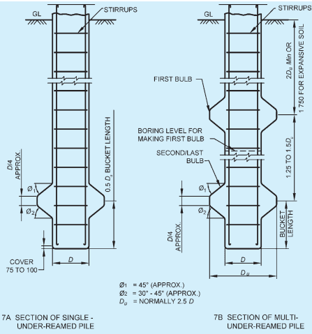
2.4.5 Bored Compaction Pile — A bored cast in-situ pile with or without bulb(s) in which the compaction of the surrounding ground and freshly filled concrete in pile bore is simultaneously achieved by a suitable method. If the pile is with bulb(s), it is known as under-reamed bored compaction pile.
2.4.6 Bored Pile — A pile formed with or without casing by excavating or boring a hole in the ground and subsequently filling it with plain or reinforced concrete.
2.4.7 Cut-off Level — It is the level where a pile is cut-off to support the pile caps or beams or any other structural components at that level.
2.4.8 Driven Cast in-situ Pile — The pile formed within the ground by driving a casing of uniform diameter, or a device to provide enlarged base and subsequently filling the hole with reinforced concrete. For displacing the subsoil the casing is driven with a plug or a shoe at the bottom. When the casing is left permanently in the ground, it is termed as cased pile and when the casing is taken out, it is termed as uncased pile. The steel casing tube is tamped during its extraction to ensure proper compaction of concrete.
2.4.9 Efficiency of a Pile Group — It is the ratio of the actual supporting value of a group of piles to the supporting value arrived at by multiplying the pile resistance of an isolated pile by their number in the group.
2.4.10 Initial Load Test — A test pile is tested to determine the load carrying capacity of the pile by loading either to its ultimate load or to twice the estimated safe load.
2.4.11 Negative Skin Friction — Negative skin friction is the force developed through the friction between the pile and the soil in such a direction as to increase the loading on the pile, generally due to drag of a consolidating soft layer around the pile resting on a stiffer bearing stratum such that the surrounding soil settles more than the pile.
2.4.12 Pile Spacing — The spacing of piles means the centre-to-centre distance between adjacent piles.
2.4.13 Precast Concrete Piles in Prebored Holes — A pile constructed in reinforced concrete in a casting yard and subsequently lowered into prebored holes and the annular space around the pile grouted.
2.4.14 Precast Driven Pile — The pile constructed in concrete in a casting yard and subsequently driven into the ground when it has attained sufficient strength.
3Site Investigation
3.1 General
Site investigation is essential in determining the physical, chemical and engineering properties of subsoil to arrive at the required foundation system. However, in areas which have already been developed, information may be obtained regarding the existing local knowledge, records of trial pits, boreholes, etc, in the vicinity, and the behaviour of the existing structures, particularly those of a similar nature to those proposed. This information may be made use of for design of foundation of lightly loaded structures of not more than two storeys and also for deciding the scope of further investigation for other structures.
3.1.1 If the existing information is not sufficient or is inconclusive, the proposed site should be explored in detail as per good practice [6-2(1)] , so as to obtain a knowledge of the type, uniformity, consistency, thickness, sequence and dip of the strata, hydrology of the area and also the engineering properties. In the case of lightly loaded structures of not more than two storeys the tests required to obtain the above information are optional, mainly depending on site conditions.
3.1.1.1 Site reconnaissance would help in deciding future programme of field investigations, that is, to assess the need for preliminary or detailed investigations. Information on some of these may be obtained from topographical maps, geological maps, pedological and soil survey maps, seismic maps and aerial photographs.
Geological maps of the area give valuable information of the site conditions. The general topography will often give some indications of the soil conditions and their variations. In certain cases the earlier uses of the land (like quarries, agricultural land, buried canals, etc) may have a very important bearing on the proposed new structures.
The presence of harmful chemicals in the subsoil can be easily identified by geology or by reconnaissance.
Data regarding removal of overburden by excavation, erosion or landslides should be obtained. This gives an idea of the amount of preconsolidation the soil strata has undergone. Similarly, data regarding recent fills is also important to study the consolidation characteristics of the fill as well as the original strata. Data regarding swelling or expansive soils will be useful information.
3.1.1.2 Ground water conditions
The ground water level fluctuates and will depend upon the permeability of the strata and the head causing the water to flow. The water level in streams and water courses, if any and wells in the vicinity give useful indications of the ground-water levels.
3.1.1.3 Rock out, crops if any may also be indicated during reconnaissance.
3.2Methods of Site Exploration
3.2.1 General
Subsurface explorations should generally be carried out in two stages, that is, preliminary and detailed.
3.2.1.1 Preliminary exploration
The investigation at this stage is to explore the feasibility aspects. The scope of preliminary exploration is restricted to the determination of depths, thickness, extent and composition of each soil stratum, location of rock and ground water and also to obtain approximate information regarding strength in compressibility of the various strata.
The number of boreholes to be explored depends upon the importance of the structure, the aerial extent of facility, the topography and the nature of sub-strata conditions. Less than five exploratory boreholes, few sounding tests, geophysical methods and often few trial pits are generally adequate in the case of preliminary exploration.
3.2.1.2 Detailed exploration
Detailed investigation follow preliminary investigation and should be planned on the basis of data obtained during review as the investigations progress. The scope of detailed exploration is generally to determine shear strength and compressibility of all types of soils, density, density index, natural moisture content and permeability. It is also necessary to determine the preconsolidation pressure of the strata from oedometer tests and consolidation characteristics beyond the preconsolidation pressure. The detailed investigation includes boring, detailed sampling and laboratory tests to determine the physical, chemical and engineering
properties of soil and rock. Field tests which may be performed are in-situ vane shear tests (suitable in case of soft cohesive soil) and plate load tests.
In a situation of liquefaction possibility, exploratory boreholes with SPT and sampling at very close depth intervals should be carried out, while static cone penetration tests with or without pore water pressure measurement are very useful. The cross hole shear tests and laboratory cyclic shear tests are useful in assessing the liquefaction potential.
NOTE — A method for assessment of liquefaction potential of a site is given in Annex J of Part 6 ‘Structural Design, Section 1 Loads, Forces and Effects’ of the Code.
3.2.1.3 The common methods of subsoil exploration are given below:
a) The most commonly used exploration procedure is boring in which different field testing procedures, like, standard penetration tests (SPT), field vane shear tests (VST), collection of undisturbed and disturbed sampling (UDS and DS), ground water table observations and field classification are employed.
b) Open trial pits — The method consists of excavating trial pits and thereby exposing the subsoil surface thoroughly, enabling undisturbed samples to be taken from the sides and bottom of the trial pits. This is suitable for all types of formations, but should be used for small depths (up to 3 m). In the case of cuts which cannot stand below water table, proper bracing should be given. The method may be used for examining the suitability of borrow pits.
Auger boring — The auger is either power or hand operated with periodic removal of the cuttings. Auger boring can be adopted in soft to stiff cohesive soils above water table. Augers shall be of helical or post hole type which may be manually or power operated. While boring, care shall be taken to minimize the disturbance to the deposits below the bottom of the borehole. The cuttings brought up by the auger shall be carefully examined in the field and the description of all the strata shall be duly recorded. No water shall be introduced from the top while conducting auger boring.
d) Shell and auger boring — Both manual and mechanized rig can be used for vertical borings. The tool normally consists of augers for soft to stiff clays, shells for very stiff and hard clays, and shells or sand pumps for sandy strata attached to sectional boring rods.
e) Wash boring — In wash boring, the soil is loosened and removed from the borehole by a stream of water or drilling mud is worked up and down or rotated in the borehole. The water or mud flow carries the soil up the annular space between the wash pipe and the casing and it overflows at ground level where the soil in suspension is allowed to settle in a pond or tank and the fluid is re-circulated as required. Samples of the settled out soil can be retained for identification purposes but this process is often unreliable. However, accurate identification can be obtained if frequent sampling is resorted to using undisturbed sample tubes.
f) Geophysical methods like electrical resistivity method and seismic method
g) Percussion boring
h) Rotary boring — In this system, boring is effected by the cutting action of a rotating bit and a mud-laden fluid or grout is pumped continuously down hollow drill rods and side of the hole.
j) Core drilling — To obtain the core samples, core drilling using double table barrel, preferably using hydraulic feed to avoid disturbance to the rock core, is used.
k) Pressure meter test (PMT) — In this, a uniform radial stress is applied to the borehole and consequent deformation is measured from which limiting pressures and modulus are obtained. This test can also be used where the sampling in hard strata becomes difficult or where there is no UDS collected. For industrial structures, 80 bars capacity energy will suffice. However for nuclear projects, higher capacity up to 200 bars may be required.
m) Plate load test — This test is conducted at shallow depths with an assumption that it directly determines the bearing capacity. Small size steel plates or relatively large RCC pads are used for conducting this test.
NOTE — While this procedure may be adequate for light or less important structures under normal conditions, relevant laboratory tests or field tests are essential in the case of unusual soil types and for all heavy and important structures. Plate load test, though useful in obtaining the necessary information about the soil with particular reference to design of foundation has some limitations. The test results reflect only the character of the soil located within a depth of less than twice the width of the bearing plate. Since the foundations are generally larger than the test plates, the settlement and shear resistance will depend on the properties of a much thicker stratum. Moreover, this method does not give the ultimate settlements particularly in case
of cohesive soils. Thus the results of the test are likely to be misleading, if the character of the soil changes at shallow depths, which is not uncommon. A satisfactory load test should, therefore, include adequate soil exploration {see good practice [6-2(2)]} with due attention being paid to any weaker stratum below the level of the footing. Another limitation is the concerning of the effect of size of foundation. For clayey soils the bearing capacity (from shear consideration) for a larger foundation is almost the same as that for the smaller test plate. But in dense sandy soils the bearing capacity increases with the size of the foundation. Thus tests with smaller size plate tend to give conservative values in dense sandy soils. It may, therefore, be necessary to test with plates of at least three sizes and the bearing capacity results extrapolated for the size of the actual foundation (minimum dimensions in the case of rectangular footings).
n) Laboratory investigation — This gives numerical values for strength, stiffness and consolidation parameters apart from the description and classification of different soil layers.
p) In-situ permeability test — In case of high water table and construction extending below the water table, prior lowering of water table would be necessary. In such situations, this test may be required.
q) Dynamic cone penetration test (DCPT)
r) Static cone penetration test (SCPT) — Apart from the above methods there are few other sounding procedures like Light Cone Penetration Tests (LCPT) and Dynamic Probing Tests (DPT), in which similar sounding techniques as in the case of DCPT are used, probably more effectively. Hydraulic feed of 20 t capacity helps to obtain data even from hard soils. For small projects 10 t hydraulic rig may suffice.
3.2.2 Number and Disposition of Test Locations
The number and disposition of various tests shall depend upon type of structure/buildings and the soil strata variations in the area. General guidelines are, however, given below:
a) For a compact building site covering an area of about 0.4 hectare, one borehole or trial pit in each corner and one in the centre should be adequate.
b) For smaller and less important buildings, even one borehole or trial pit in the centre will suffice.
c) For very large areas covering industrial and residential colonies, the geological nature of the terrain will help in deciding the number of boreholes and trial pits. For various commercial, industrial, infrastructure, power plants, cement plants, petrochemical plants,
steel plants, pump house on shore or offshore, etc, number of boreholes and/or trial pits should be decided considering the importance of structure and type as well as uniformity of strata. As a guide, dynamic or static cone penetration tests may be performed at every 100 m by dividing the area in a grid pattern and the number of boreholes or trial pits may be decided by examining the variation in the penetration curves. The cone penetration tests may not be possible at sites having generally gravelly/bouldery strata. In such cases, geophysical methods may be resorted to.
3.2.3 Depth of Exploration
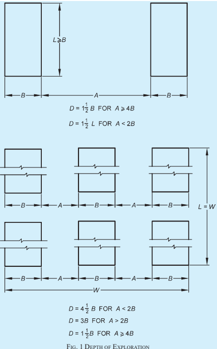
The depth of exploration required depends on the type of proposed structure, its total weight, the size, shape and disposition of the loaded areas, soil profile, and the physical properties of the soil that constitutes each individual stratum. The borings should be extended to strata of adequate bearing capacity and should penetrate all deposits which are unsuitable for foundation purposes, such as, unconsolidated fill, peat, organic silt and very soft and compressible clay. Normally, it should be one and a half times the width of the footing below foundation level. In certain cases, it may be necessary to take at least one borehole or cone test or both to twice the width of the foundation. If a number of loaded areas are in close proximity the effect of each is additive. In such cases, the whole of the area may be considered as loaded and exploration should be carried out up to one and a half times the lower dimension. In weak soils, the exploration should be continued to a depth at which the loads can be carried by the stratum in question without undesirable settlement and shear failure. In any case, the depth to which seasonal variations affect the soil should be regarded as the minimum depth for the exploration of sites. But where industrial processes affect the soil characteristics, this depth may be more. The presence of fast growing and water seeking trees also contributes to the weathering processes.
NOTE — Examples of fast growing and water seeking trees are Banyan (Ficusbengalensis), Pipal (Ficusreligiosa) and Neem (Azadirachtaindica).
3.2.3.1 An estimate of the variation with depth of the vertical normal stress in the soil arising from foundation loads may be made on the basis of elastic theory. The net loading intensity at any level below a foundation may be obtained approximately by assuming a spread of load of two vertical to one horizontal from all sides of the foundations, due allowance being made for the overlapping effects of load from closely spaced footings. As a general guidance, the depth of exploration at the start of the work may be decided as
given in Table 1, which may be modified as exploration proceeds, if required. However, for industrial plant and other main structures, the depth of exploration may be decided depending upon importance of structure, loading conditions and type as well as uniformity of
strata. For piles or piers, the depth shall be at least (2)/(3) L below the anticipated tip (that is, termination of pile) or 5.0m in rock with rock quality designation (RQD) ≥ 50 percent, whichever is earlier.
Table 1Depth of Exploration (Clause 3.2.3.1)
Sl No.(1)
Type of Foundation(2)
Depth of ExplorationD(3)
i)
Isolated spread footing or raft
3.2.4 Vertical Interval for Field Tests
Normally, once the type of foundation is decided as shallow footings based on initial findings, the test intervals shall be close to almost continuous at least for a depth equal to 1.5 times the foundation width.
Similarly, in the case of pile foundations, the test intervals shall be significantly small within a depth range of eight times the pile diameter above the pile tip and five times the pile diameter below the pile tip until incompressible stratum is encountered and confined geologically.
In case of housing colonies, the depth of borehole may be kept as 40 m or 5 m in rock with rock quality designation RQD ≥ 25 percent, whichever is earlier.
In the case of ground improvement programme like pre-loading, stone columns, compaction, etc, the field tests and sampling shall be almost continuous so that presence of thin soil layers of different texture can be identified.
3.3Choice of Method for Site Exploration
The choice of the method depends on the following factors.
3.3.1 Nature of Ground
a) Soils — In clayey soils, borings are suitable for
FIG. 1 DEPTH OF EXPLORATION
deep exploration and pits for shallow exploration. In case of soft sensitive clayey soils, field vane shear test may be carried out with advantage.
In sandy soils, boring is easy but special equipment, such as, Bishop or Osterberg piston samplers should be used for taking undisturbed samples below the water table. Where necessary, some form of ground water lowering is used. Standard penetration test, dynamic cone penetration test and static cone penetration test are used to assess engineering properties.
b) Gravel-boulder deposits — In the deposits where gravel-boulder proportion is large (>30 percent), the subsoil strata should be
explored by open trial pits of about 5 m × 5 m but in no case less than 2 m × 2 m . The depth of excavation may be up to 6 m . For determining strata characteristics, in-situ tests should be preferred. For shear characteristics and allowable soil pressure, pressure meter tests, load tests on cast in-situ footing and in-situ shear tests that is, boulder-boulder test or concrete-boulder test are more appropriate. For detailed information on these tests reference shall be made to good practice [6-2(3)]. Depending on the structure, if required, the strata may be explored by drilling borehole using suitable method.
c) Rocks — Core drillings are suitable in hard rocks and pits in soft rocks. Core borings are suitable for the identification of types of rock, but they provide limited data on joints and fissures. NX borehole camera is useful to photograph the stratification in drilled boreholes. For obtaining core, double tube core barrel with hydraulic feed is preferred. Triple tube core barrel may be used in fragmented or failure or sheared rock. Depending upon the design requirements, large diameter drilling may be explored if feasible.
3.3.2 Topography
In hilly country, the choice between vertical openings (for example, borings and trial pits) and horizontal openings (for example, headings) may depend on the geological structure, since steeply inclined strata are most effectively explored by headings and horizontal strata by trial pits or borings. Swamps and areas overlain by water are best explored by borings which may require use of a floating craft.
3.3.3 Cost
The cost of investigation varies depending upon project size, stratigraphy, location, marshy areas' access or approaches, etc. The data to be obtained for founding purpose, with a view to reducing or minimizing the surprises, is however, important. It also helps in solutions in respect of selection of appropriate type of foundation, construction materials, etc. For deep exploration, borings are usual, as deep shafts are costly. For shallow exploration in soil, the choice between pits and borings will depend on the nature of the ground and the information required by shallow exploration in rock; the cost of bringing a core drill to the site will be justified only, if several holes are required; otherwise, trial pits will be more economical.
3.4Sampling and Testing
3.4.1 Methods of Sampling
a) Disturbed samples — These are taken by methods which modify or destroy the natural structure of the material though with suitable precautions the natural moisture content can be preserved.
b) Undisturbed samples (UDS) — These are taken by methods which preserve the structure and properties of the material. Thin walled tube samples may be used for undisturbed samples in soils of medium strength and tests for the same may be carried out in accordance with good practice [6-2(1)]. Minimum one UDS shall be obtained from each cohesive layer. For thick layers, the UDS shall be taken at every 3 m intervals. UDS need not be taken from cohesion less soils (silty sand, sand and gravel).
NOTE — In case of loose sandy soils and soft
soils, specially below water table it may not be possible to take undisturbed sample, in which case other suitable methods may be adopted for exploration.
c) Representative samples — These samples have all their constituent parts preserved, but may or may not be structurally disturbed. Washed samples from rotary boring should not be collected.
3.4.1.1 The methods usually employed are:
Sl No.(1)
Nature of Ground(2)
Type of Sample(3)
Method of Sampling(4)
i) Soil
a) Disturbed
Chunk samplesAuger samples (for example, in clay)Shell samples (for example, in sand)
b) Undisturbed
Chunk samplesTube samples
ii) Rock
a) Disturbed
Wash samples from percussion or rotary drilling
b) Undisturbed
Core barrel sampling
3.4.2 Soil Samples
a) Disturbed soil samples — The mass of sample generally required for testing purposes is given in Table 2.
Table 2 Mass of Soil Sample Required[Clause 3.4.2(a)]
Sl No.
Purpose of Sample
Type
Mass of Sample Required kg(4)
(1)
(2)
(3)
i) Soil identification, natural moisture content tests, mechanical analysis and index properties
a) Cohesive soil
1
Chemical tests
b) Sands and gravels
3
ii) Compaction tests
a) Cohesive soils and sands
12.5
b) Gravely soils
25
iii) Comprehensive examination of construction materials including stabilization
a) Cohesive soils and sands
25 to 50
b) Gravely soils
50 to 100
NOTES1 The schedule for laboratory tests shall include the representative of the sub-strata layer for testing physical, engineering and chemical properties of soil and rock.2 Additional tests, if any required for assessing suitability of borrow material may also be included.
b) Undisturbed soil samples — The core diameter of the sample shall be 75 mm to 100 mm diameter and it shall preferably be 300 mm long. The upper few millimetres of the sample should be rejected as the soil at the bottom of the borehole usually gets disturbed by the boring tools.
3.4.3 Rock Samples
a) Disturbed samples — The sludge from percussion borings, or from rotary borings which have failed to yield a core, may be taken as a disturbed sample.
b) Undisturbed samples
Block samples — Such samples taken from the rock formation shall be dressed to a size convenient for packing to about 90 mm × 75 mm × 50 mm .
Core samples — Cores of rock shall be taken by means of rotary drills fitted with a coring bit with core retainer {see also good practice [6-2(4)]}.
3.4.4 Water Samples
Water samples have to be collected for chemical analysis. In cases, where mud circulation is used for advancing and stabilizing the boreholes, water samples are to be collected only after 24 h of completion of the borehole. The other option is to collect water samples from open wells in the close proximity. The sample shall be collected in a plastic container (about 500 ml) with airtight cover.
3.4.5 Protection, Handling and Labelling of Samples
Care should be taken in protecting, handling and subsequent transport of samples and in their full labelling, so that samples can be received in a fit state for examination and testing, and can be correctly recognized as coming from a specified trial pit or boring.
3.4.6 Examination and Testing of Samples
3.4.6.1 The following tests shall be carried out in accordance with accepted standard [6-2(5)]:
a) Tests on undisturbed and disturbed samples
Visual and engineering classification;
Sieve analysis and hydrometer analysis;
Liquid, plastic, and shrinkage limits;
Specific gravity;
Chemical analysis (sulphate, chloride and pH content of soil and ground water);
Swell pressure and free swell index determination;
Proctor compaction test; and
California bearing ratio.
b) Test on undisturbed samples
Bulk density and moisture content;
Relative density (for sand);
Unconfined compression test;
Box shear test (in case of cohesionless and c- φ soil);
Triaxial shear tests (depending on the type of soil and field conditions on undisturbed or remoulded samples):
i) Unconsolidated undrained,
ii) Consolidated undrained test with the measurement of pore water pressure, and
iii) Consolidated drained;
Consolidation test; and
Laboratory permeability test.
c) Test on rock samples
Visual classification;
Water absorption, porosity and density;
Specific gravity;
Hardness;
Slake durability;
Unconfined compression test (both saturated and at in-situ water content);
Point load strength index; and
Deformability test (both saturated and dry samples). NOTE — These tests may be reduced according to engineering requirements.
5Materials
5.1 Cement, coarse aggregate, fine aggregate, lime, Surkhi, steel, timber and other materials go into the construction of foundations shall conform to the requirements of Part 5 'Building Materials' of the Code.
5.2 Protection Against Deterioration of Materials
Where a foundation is to be in contact with soil, water or air, that is, in a condition conducive to the deterioration of the materials of the foundation, protective measures shall be taken to minimize the deterioration of the materials.
5.2.1 Concrete
The concrete used for construction shall be in accordance with Part 6 ‘Structural Design, Section 5 Concrete’ of the Code.
5.2.2 Timber
Where timber is exposed to soil, it shall be treated in accordance with good practice [6-2(7)].
6 GENERAL REQUIREMENTS FOR FOUNDATIONS/SUBSTRUCTURES FOR BUILDINGS
6.2Depth of Foundations
6.2.1 The depth to which foundations should be carried depends upon the following principal factors:
a) Securing of adequate allowable capacity.
b) In the case of clayey soils, penetration below the zone where shrinkage and swelling due to seasonal weather changes, and due to trees and shrubs are likely to cause appreciable movements.
c) In fine sands and silts, penetration below the zone in which trouble may be expected from frost.
d) Maximum depth of scour, wherever relevant, should also be considered and the foundation should be located sufficiently below this depth.
e) Other factors such as ground movements and heat transmitted from the building to the supporting ground may be important.
6.2.2 All foundations shall extend to a depth of at least 500 mm below natural ground level. On rock or such other weather resisting natural ground, removal of the top soil may be all that is required. In such cases, the surface shall be cleaned and, if necessary, stepped or otherwise prepared so as to provide a suitable bearing and thus prevent slipping or other unwanted movements.
6.2.3 Where there is excavation, ditch pond, water course, filled up ground or similar condition adjoining or adjacent to the subsoil on which the structure is to be erected and which is likely to impair the stability of structure, either the foundation of such structure shall be carried down to a depth beyond the detrimental influence of such conditions, or retaining walls or similar works shall be constructed for the purpose of shielding from their effects.
6.2.4 A foundation in any type of soil shall be below the zone significantly weakened by root holes or cavities produced by burrowing animals or works. The depth shall also be enough to prevent the rainwater scouring below the footings.
6.2.5 Clay soils, like black cotton soils, are seasonally affected by drying, shrinkage and cracking in dry and hot weather, and by swelling in the following wet weather to a depth which will vary according to the nature of the clay and the climatic condition of the region. It is necessary in these soils, either to place the foundation bearing at such a depth where the effects of seasonal changes are not important or to make the foundation capable of eliminating the undesirable effects due to relative movement by providing flexible type of construction or rigid foundations. Adequate load counteracting against swelling pressures also provide satisfactory foundations.
6.4Effect of Seasonal Weather Changes
During periods of hot, dry weather a deficiency of water develops near the ground surface and in clay soils, that is associated with a decrease of volume or ground shrinkage and the development of cracks. The shrinkage of clay will be increased by drying effect produced by fast growing and water seeking trees. The range of influence depends on size and number of trees and it increase during dry periods. In general, it is desirable that there shall be a distance of at least 8 m between such trees. Boiler installations, furnaces, kilns, underground cables and refrigeration installations and other artificial sources of heat may also cause increased volume changes of clay by drying out the ground beneath them, the drying out can be to a substantial depth. Special precautions either in the form of insulation or otherwise should be taken. In periods of wet weather, clay soils swell and the cracks lend to close, the water deficiency developed in the previous
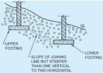
FIG. 3 FOOTING IN GRANULAR SOIL
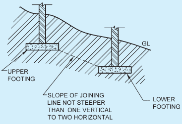
FIG. 4 FOOTING IN CLAYEY SOIL
dry periods may be partially replenished and a subsurface zone or zones deficient in water may persist for many years. Leakage from water mains and underground sewers may also result in large volume changes. Therefore, special care shall be taken to prevent such leakages.
6.3Foundation at Different Levels
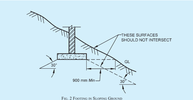
6.3.1 Where footings are adjacent to sloping ground or where the bottoms of the footings of a structure are at different levels or at levels different from those of the footings of adjoining structures, the depth of the footings shall be such that the difference in footing elevations shall be subject to the following limitations:
a) When the ground surface slopes downward adjacent to a footing, the sloping surface shall not intersect a frustum of bearing material under the footing having sides which make an angle of 30° with the horizontal for soil and horizontal distance from the lower edge of the footing to the sloping surface shall be at least 600 mm for rock and 900 mm for soil (see Fig. 2).
b) In the case of footings in granular soil, a line drawn between the lower adjacent edges of adjacent footings shall not have a steeper slope than one vertical to two horizontal (see Fig. 3).
c) In case of footing in clayey soils a line drawn between the lower adjacent edge of the upper footing and the upper adjacent edge of lower footing shall not have a steeper slope than one vertical to two horizontal (see Fig. 4).
6.3.2 The requirement given in 6.3.1 shall not apply in the condition where adequate provision is made for the lateral support (such as with retaining walls) of the material supporting the higher footing.
6.5Effect of Mass Movements of Ground in Unstable Areas
In certain areas mass movements of the ground are liable to occur from causes independent of the loads applied by the foundations of structures. These include mining subsidence, landslides on unstable slopes and creep on clay slopes.
6.5.1 Mining Subsidence
In mining areas, subsidence of the ground beneath a building or any other structure is liable to occur. The magnitude of the movement and its distribution over the area are likely to be uncertain and attention shall,
therefore, be directed to make the foundations and structures sufficiently rigid and strong to withstand the probable worst loading condition and probable ground movements. Long continuous buildings should be avoided in such areas and large building in such area should be divided into independent sections of suitable size, each with its own foundations. Expert advice from appropriate mining authority should be sought.
NOTE — For prediction of subsidence in coal mines, guidelines as given in the good practice [6-2(8)] may be referred.
6.5.2 Landslide Prone Areas
The construction of structures on slopes which are suspected of being unstable and are subject to landslip shall be avoided.
On sloping ground on clay soils, there is always a tendency for the upper layers of soil to move downhill, depending on type of soil, the angle of slope, climatic
conditions, etc. In some cases, the uneven surface of the slope on a virgin ground will indicate that the area is subject to small land slips and, therefore, if used for foundation, will obviously necessitate special design consideration.
Where there may be creep of the surface layer of the soil, protection against creep may be obtained by following special design considerations.
On sloping sites, spread foundations shall be on a horizontal bearing and stepped. At all changes of levels, they shall be lapped at the steps for a distance at least equal to the thickness of the foundation or twice the height of the step, whichever is greater. The steps shall not be of greater height than the thickness of the foundation, unless special precautions are taken.
Cuttings, excavations or sloping ground near and below foundation level may increase the possibility of shear failure of the soil. The foundation shall be well beyond the zone of such shear failure.
If the probable failure surface intersects a retaining wall or other revetment, the latter shall be made strong enough to resist any unbalanced thrust. In case of doubt as to the suitability of the natural slopes or cuttings, the structure shall be kept well away from the top of the slopes, or the slopes shall be stabilized.
Cuttings and excavations adjoining foundations reduce stability and increase the likelihood of differential settlement. Their effect should be investigated not only when they exist but also when there is possibility that they are made subsequently.
Where a structure is to be placed on sloping ground, additional complications are introduced. The ground itself, particularly if of clay, may be subject to creep or other forms of instability, which may be enhanced if the strata dip in the same direction as the ground surface. If the slope of the ground is large, the overall stability of the slope and substructure may be affected. These aspects should be carefully investigated.
6.6 Precautions for Foundations on Inclined Strata
In the case of inclined strata, if they dip towards a cutting of basement, it may be necessary to carry foundation below the possible slip planes, land drainage also requires special consideration, particularly on the uphill side of a structure to divert the natural flow of water away from the foundations.
6.7 Strata of Varying Thickness
Strata of varying thickness, even at appreciable depth, may increase differential settlement. Where necessary, calculations should be made of the estimated settlement
from different thickness of strata and the structure should be designed accordingly. When there is large change of thickness of soft strata, the stability of foundation may be affected. Site investigations should, therefore, ensure detection of significant variations in strata thickness.
6.8 Layers of Softer Material
Some soils and rocks have thin layers of softer material between layers of harder material, which may not be detected unless thorough investigation is carried out. The softer layers may undergo marked changes in properties if the loading on them is increased or decreased by the proposed construction or affected by related changes in ground water conditions. These should be taken into account.
6.9 Spacing Between Existing and New Foundation
The deeper the new foundation and the nearer to the existing it is located, the greater the damage is likely to be. The minimum horizontal spacing between existing and new footings shall be equal to the width of the wider one. While the adoption of such provision shall help minimizing damage to adjacent foundation, an analysis of bearing capacity and settlement shall be carried out to have an appreciation of the effect on the adjacent existing foundation.
6.10Preliminary Work for Construction
6.10.1 The construction of access roads, main sewers and drains should preferably be completed before commencing the work of foundations; alternatively, sufficient precautions shall be taken to protect the already constructed foundations during subsequent work.
6.10.2 Clearance of Site
Any obstacles, including the stump of trees, likely to interfere with the work shall be removed. Holes left by digging, such as those due to removal of old foundation, uprooted trees, burrowing by animals, etc, shall be back-filled with soil and well compacted.
6.10.3 Drainage
If the site of a structure is such that surface water shall drain towards it, land may be dressed or drains laid to divert the water away from the site.
6.10.4 Setting Out
Generally the site shall be levelled before the layout of foundations are set out. In case of sloping terrain, care shall be taken to ensure that the dimensions on plans are set out correctly in one or more horizontal planes.
6.10.5 The layout of foundations shall be set out with steel tapes. Angles should be set out with theodolites
in the case of important and intricate structures where the length of area exceeds 16 m. In other cases these shall be set out by measurement of sides. In rectangular or square setting out, diagonals shall be checked to ensure accuracy. The setting out of walls shall be facilitated by permanent row of pillars, parallel to and at a suitable distance beyond the periphery of the building. The pillars shall be located at junctions of cross walls with the peripheral line of pillars. The centre lines of the cross walls shall be extended to and permanently erected on the plastered tops of the corresponding sets of pillars. The datum lines parallel to and at the known fixed distance from the centre lines of the external walls also be permanently worked on the corresponding rows of pillars to pillars to serve as checks on the accuracy of the work as it proceeds. The tops of these pillars shall be at the same level and preferably at the plinth or floor level. The pillars shall be of sizes not less than 250 mm wide and shall be bedded sufficiently deep into ground, so that they are not disturbed.
6.11Protection of Excavation
6.11.1 The protection of excavation during construction of timbering and dewatering operations, where necessary, shall be done in accordance with [6-2(9)].
6.11.2 After excavation, the bottom of the excavation shall be cleared of all loose soil and rubbish and shall be levelled, where necessary. The bed shall be wetted and compacted by heavy rammers to an even surface.
6.11.3 Excavation in clay or other soils that are liable to be effected by exposure to atmosphere shall, wherever possible, be concreted as soon as they are dug. Alternatively, the bottom of the excavation shall be protected immediately by 8 cm thick layer of cement concrete not leaner than mix 1:5:10 over which shall come the foundation concrete; or in order to obtain a dry hard bottom, the last excavation of about 10 cm shall be removed only before concreting.
6.11.4 The refilling of the excavation shall he done with care so as not to disturb the constructed foundation, and shall be compacted in layers not exceeding 15 cm thick with sprinkling of minimum quantity of water necessary for proper compaction.
6.12Alterations During Construction
a) Where during construction the soil or rock to which foundation is to transfer loads is found not to be the type or in the condition assumed, the foundation shall be redesigned and constructed for the existing type or conditions and the Authority notified.
b) Where a foundation bears on gravel, sand or silt and where the highest level of the ground
water is or likely to be higher than an elevation defined by bearing surface minus the width of the footing, the bearing pressure shall be suitably altered.
c) Where the foundation has not been placed or located as indicated earlier or is damaged or bears on a soil whose properties may be adversely changed by climatic and construction conditions, the error shall be corrected, the damaged portion repaired or the design capacity of the affected foundation recalculated to the satisfaction of the Authority.
d) Where a foundation is placed, and if the results of a load test so indicate, the design of the foundation shall be modified to ensure structural stability of the same.
7.2Design Considerations
7.2.1 Design Loads
The foundation shall be proportioned for the following combination of loads:
a) Dead load + Imposed load; and
b) Dead load + Imposed load + Wind load or seismic loads, whichever is critical.
For details, reference shall be made to Part 6 ‘Structural Design, Section 1 Loads, Forces and Effects’ of the Code.
NOTE — For shallow foundations on coarse grained soils, settlements shall be estimated corresponding to 7.2.1 (b) and for foundations on fine grained soils, the settlement shall be estimated corresponding to permanent loads only. Permanent loads shall be in accordance with good practice [6-2(10)].
7.2.2 Allowable Bearing Pressure
The allowable bearing pressure shall be taken as either of the following, whichever is less:
a) The safe bearing capacity on the basis of shear strength characteristics of soil, or
b) The bearing pressure that the soil can take without exceeding the permissible settlement (see 7.2.3).
7.2.2.1 Bearing capacity by calculation
Where the engineering properties of the soil are available, that is, cohesion, angle of internal friction, density, etc, the bearing capacity shall be calculated from stability considerations of shear; factor of safety of 2.5 shall be adopted for safe bearing capacity. The effect of interference of different foundations should be taken into account. The procedure for determining the ultimate bearing capacity and bearing pressure of shallow foundations based on shear and allowable settlement criteria shall be in accordance with good practice [6-2(11)]. Depth factor correction is to be applied only when backfilling is done with proper compaction.
7.2.2.2 Field method for determining allowable bearing pressure
Where appropriate, plate load tests can be performed and allowable pressure determined as per accepted standard [6-2(12)]. The allowable bearing pressure for sandy soils may also be obtained by loading tests. When such tests cannot be done, the allowable bearing pressure for sands may be determined using penetration test.
7.2.2.3 Where the bearing materials directly under a foundation overlie a stratum having smaller safe bearing capacity, these smaller values shall not be exceeded at the level of such stratum.
7.2.2.4 Effect of wind and seismic force
7.2.2.4.1 Where the bearing pressure due to wind is less than 25 percent of that due to dead and imposed loads, it may be neglected in design. Where this exceeds 25 percent, foundations may be so proportioned that the pressure due to combined dead, imposed and wind loads does not exceed the allowable bearing pressure by more than 25 percent.
7.2.2.4.2 When earthquake forces are considered for the computation of design loads, the permissible
increase in bearing pressure of pertaining soil shall be as given in 5.3.3.5 of Part 6 ‘Structural Design, Section 1 Loads, Forces and Effects’ of the Code, depending upon the type of foundation of the structure and the type of soil.
7.2.2.5 Bearing capacity of buried strata
If the base of a foundation is close enough to a strata of lower bearing capacity, the latter may fail due to excess pressure transmitted to it from above. Care should be taken to see that the pressure transmitted to the lower strata is within the prescribed safe limits. When the footings are closely spaced, the pressure transmitted to the underlying soil will overlap. In such cases, the pressure in the overlapped zones will have to be considered. With normal foundations, it is sufficiently accurate to estimate the bearing pressure on the underlying layers by assuming the load to be spread at a slope of 2 (vertical) to 1 (horizontal).
7.2.3 Settlement
The permissible values of total and differential settlement for a given type of structure may be taken as given in Table 3. Total settlements of foundation due to net imposed loads shall be estimated in accordance with good practice [6-2(13)]. The following causes responsible for producing the settlement shall be investigated and taken into account.
a) Causes of settlement
Elastic compression of the foundation and the underlying soil,
Consolidation including secondary compression,
Ground water lowering — Specially repeated lowering and raising of water level in loose granular soils tend to compact the soil and cause settlement of the footings. Prolonged lowering of the water table in fine grained soils may introduce settlement because of the extrusion of water from the voids. Pumping water or draining water by tiles or pipes from granular soils without an adequate mat of filter material as protection may, in a period of time, carry a sufficient amount of fine particles away from the soil and cause settlement.
Seasonal swelling and shrinkage of expansive clays.
Ground movement on earth slope, for example, surface erosion, slow creep or landslides.
Other causes, such as adjacent excavation, mining, subsidence and underground erosion.
Table 3Permissible Differential Settlements and Tilt (Angular Distortion) for Shallow Foundations in Soils (Clause 7.2.3)
Sl No.
Type of Structure
Isolated Foundations
Raft Foundations
Sand and Hard Clay
Plastic Clay
Sand and Hard Clay
Plastic Clay
Maximum Settlement
Differential Settlement
Angular Distortion
Maximum Settlement
Differential Settlement
Angular Distortion
Maximum Settlement
Differential Settlement
Angular Distortion
Maximum Settlement
Differential Settlement
Angular Distortion
(1)
(2)
mm (3)
mm (4)
(5)
mm (6)
mm (7)
(8)
mm (9)
mm (10)
(11)
mm (12)
mm (13)
(14)
i)
For steel structure
50
.003 3L
1/300
50
.003 3L
1/300
75
7.2.4 Shallow Foundations on Rocks
Estimation of the safe bearing pressures of rocks for shallow foundations based on strength, allowable settlement and classification criteria; and also design and construction of shallow foundations on rocks shall be carried out in accordance with the good practice [6-2(14)].
7.3Pad or Spread and Strip Foundations
7.3.1 In such type of foundations, wherever the resultant of the load deviates from the centre line by more than 1/6 of its least dimension at the base of footing, it should be suitably reinforced.
7.3.2 For continuous wall foundations (plain or reinforced) adequate reinforcement should be provided particularly at places where there is abrupt change in magnitude of load or variation in ground support.
7.3.3 On sloping sites the foundation should have a horizontal bearing and stepped and lapped at changes
of levels for a distance at least equal to the thickness of foundation or twice the height of step, whichever is greater. The steps should not be of greater height than thickness of the foundations.
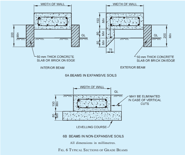
7.3.4 Ground Beams
The foundation can also have the ground beam for transmitting the load. The ground beam carrying a load bearing wall should be designed to act with the wall forming a composite beam, when both are of reinforced concrete and structurally connected by reinforcement. The ground beam of reinforced concrete structurally connected to reinforced brick work can also be used.
7.3.5 Dimensions of Foundation
The dimensions of the foundation in plan should be such as to support loads as given in good practice [6-2(10)]. The width of the footings shall be such that maximum stress in the concrete or masonry is within the permissible limits. The width of wall foundation (in mm) shall not be less than that given by:
B = W + 3 0 0
where
B = width at base, in mm; and
W = width of supported wall, in mm.
7.3.6 In the base of foundations for masonry foundation it is preferable to have the steps in multiples of thickness of masonry unit.
7.3.7 The plan dimensions of excavation for foundations should be wide enough to ensure safe and efficient working in accordance with good practice [6-2(9)].
7.3.8 Unreinforced foundation may be of concrete or masonry (stone or brick) provided that angular spread of load from the base of column/wall or bed plate to the outer edge of the ground bearing is not more than 1 vertical to 1/2 horizontal for masonry or 1 vertical to 1 horizontal for cement concrete and 1 vertical to 2/3 horizontal for lime concrete. The minimum thickness of the foundation of the edge should not be
less than 150 mm. In case the depth to transfer the load to the ground bearing is less than the permissible angle of spread, the foundations should be reinforced.
7.3.9 If the bottom of a pier is to be belled so as to increase its load carrying capacity such bell should be at least 300 mm thick at its edge. The sides should be sloped at an angle of not less than 45° with the horizontal. The least dimension should be 600 mm (circular, square or rectangular). The design should allow for the vertical tilt of the pier by 1 percent of its height.
7.3.10 If the allowable bearing capacity is available only at a greater depth, the foundation can be rested at a higher level for economic considerations and the difference in level between the base of foundation and the depth at which the allowable bearing capacity occurs can be filled up with either: (a) concrete of allowable compressive strength not less than the allowable bearing pressure, (b) incompressible fill material, for example, sand, gravel, etc, in which case the width of the fill should be more than the width of the foundation by an extent of dispersion of load from the base of the foundation on either side at the rate of 2 vertical to 1 horizontal.
7.3.11 The cement concrete foundation (plain or reinforced) should be designed in accordance with Part 6 ‘Structural Design, Section 5 Concrete, Subsection 5A Plain and Reinforced Concrete’ of the Code and masonry foundation in accordance with Part 6 ‘Structural Design, Section 4 Masonry’ of the Code.
7.3.12 Thickness of Footing
The thickness of different types of footings, if not designed according to 7.2, should be as given in Table 4.
7.3.13 Land Slip Area
On a sloping site, spread foundation shall be on a horizontal bearing and stepped. At all changes of levels, they shall be lapped at the steps for a distance at least equal to the thickness of the foundation or twice the
Table 4 Thickness of Footings(Clause 7.3.12)
SI No.(1)
Type of Footings(2)
Thickness of Footings, Min(3)
Remarks(4)
i)
Masonry
a) 250 mmb) Twice the maximum projection from the face of the wall
Select the greater of the two values
ii)
Plain concrete:
a) For normal structures
a) 200 mmb) Twice the maximum offset in a stepped footingc) 300 mm
—For footings resting on soilFor footings resting on top of the pileResting on soilResting on pile
b) For lightly loaded structures
a) 150 mmb) 200 mm
iii)
Reinforced concrete
a) 150 mmb) 300 mm
Resting on soilResting on pile
height of the step, whichever is greater. The steps shall not be of greater height than the thickness of the foundation unless special precautions are taken. On sloping ground on clay soils, there is always a tendency for the upper layers of soil to move downhill, depending on type of soil, the angle of slope, climatic conditions, etc. Special precautions are necessary to avoid such a failure.
7.3.14 In the foundations, the cover to the reinforcement shall be as prescribed in Part 6 ‘Structural Design, Section 5 Concrete, Subsection 5A Plain and Reinforced Concrete’ of the Code for the applicable environment exposure condition.
7.3.15 For detailed information regarding preparation of ground work, reference shall be made to good practice [6-2(15)].
7.4Raft Foundations
7.4.1 Design Considerations
Design provisions given in 7.2 shall generally apply.
7.4.1.1 The structural design of reinforced concrete rafts shall conform to Part 6 ‘Structural Design, Section 5 Concrete, Subsection 5A Plain and Reinforced Concrete’ of the Code.
7.4.1.2 In the case of raft, whether resting on soil directly or on lean concrete, the cover to the reinforcement shall be as prescribed in Part 6 ‘Structural Design, Section 5 Concrete, Subsection 5A Plain and Reinforced Concrete’ of the Code for the applicable environment exposure condition.
7.4.1.3 In case the structure supported by the raft consists of several parts with varying loads and heights, it is advisable to provide separation joints between these parts. Joints shall also be provided, wherever there is a change in the direction of the raft.
7.4.1.4 Foundations subject to heavy vibratory loads should preferably be isolated.
7.4.1.5 The minimum depth of foundation shall generally be not less than 1m.
7.4.1.6 Dimensional parameters
The size and shape of the foundation adopted affect the magnitude of subgrade modulus and long term deformation of the supporting soil and this, in turn, influences the distribution of contact pressure. This aspect needs to be taken into consideration in the analysis.
7.4.1.7 Eccentricity of loading
A raft generally occupies the entire area of the building and often it is not feasible and rather uneconomical to proportion it coinciding the centroid of the raft with the line of action of the resultant force. In such cases, the effect of the eccentricity on contact pressure distribution shall be taken into consideration.
7.4.1.8 Properties of supporting soil
Distribution of contact pressure underneath a raft is affected by the physical characteristics of the soil supporting it. Consideration shall be given to the increased contact pressure developed along the edges of foundation on cohesive soils and the opposite effect on granular soils. Long term consolidation of deep soil layers shall be taken into account in the analysis. This may necessitate evaluation of contact pressure distribution both immediately after construction and after completion of the consolidation process. The design shall be based on the worst conditions.
7.4.1.9 Rigidity of foundations
Rigidity of the foundation tends to iron out uneven deformation and thereby modifies the contact pressure distribution. High order of rigidity is characterized by long moments and relatively small, uniform settlements. A rigid foundation may also generate high secondary stresses in structural members. The effect of rigidity shall be taken into account in analysis.
7.4.1.10 Rigidity of the super structure
Free response of the foundations to soil deformation is restricted by the rigidity of the superstructure. In the extreme case, a stiff structure may force a flexible foundation to behave as rigid. This aspect shall be considered to evaluate the validity of the contact pressure distribution.
7.4.1.11 Modulus of elasticity and modulus of subgrade reaction
Annex A enumerates the methods of determination of modulus of elasticity ( Es ). The modulus of subgrade reaction (k) may be determined in accordance with Annex B.
7.4.2 Necessary Information
The following information is necessary for a satisfactory design and construction of a raft foundation:
a) Site plan showing the location of the proposed as well as the neighbouring structures;
b) Plan and cross-sections of building showing different floor levels, shafts and openings, etc, layout of loading bearing walls, columns, shear walls, etc;
c) Loading conditions, preferably shown on a schematic plan indicating combination of design loads transmitted to the foundation;
d) Information relating to geological history of the area, seismicity of their area, hydrological information indicating ground water conditions and its seasonal variations, etc;
e) Geotechnical information giving subsurface profile with stratification details, engineering
properties of the founding strata (namely, index properties, effective shear parameters determined under appropriate drainage conditions, compressibility characteristics, swelling properties, results of field tests like static and dynamic penetration tests, pressure meter tests, etc); and
f) A review of the performance of similar structure, if any, in the locality.
7.4.3 Choice of Raft Type
7.4.3.1 For fairly small and uniform column spacing
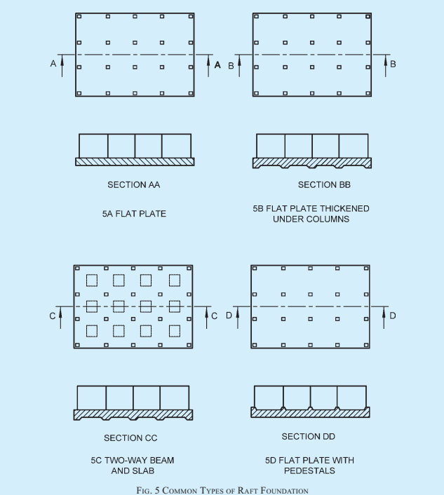
and when the supporting soil is not too compressible a flat concrete slab having uniform thickness throughout (a true mat) is most suitable (see Fig. 5A).
7.4.3.2 A slab may be thickened under heavy loaded columns to provide adequate strength for shear and negative moment. Pedestals may also be provided in such cases (see Fig. 5B).
7.4.3.3 A slab and beam type of raft is likely to be more economical for large column spacing and unequal column loads particularly when the supporting soil is very compressive (see Fig. 5C and Fig. 5D).
7.4.3.4 For very heavy structures, provision of cellular raft or rigid frames consisting of slabs and basement walls may be considered.
7.4.4 Methods of Analysis
The essential task in the analysis of a raft foundation is the determination of the distribution of contact pressure underneath the raft which is a complex function of the rigidity of the superstructure, the supporting soil and the raft itself, and cannot be determined with exactitude, except in very simple cases. This necessitates a number of simplifying assumptions to make the problem amenable to analysis. Once the distribution of contact pressure is determined, design bending moments and shears can be computed based on statics. The methods of analysis suggested are distinguished by the assumptions involved. Choice of a particular method should be governed by the validity of the assumptions in the particular case.
7.4.4.1 Rigid foundation (conventional method)
This method is based on the assumption of linear distribution of contact pressure. The basic assumptions of this method are,
a) the foundations rigid relative to the supporting soil and the compressible soil layer is relatively shallow; and
b) the contact pressure variation is assumed as planar, such that the centroid of the contact pressure coincides with the line of action of the resultant force of all loads acting on the foundation.
This method may be used when either of the following conditions is satisfied:
The structure behaves as rigid (due to the combined action of the superstructure and the foundation) with relative stiffness factor K>0.5 (for evaluation of K, see Annex C); and
The column spacing is less than 1.75 / λ (see Annex C).
The raft is analyzed as a whole in each of the two perpendicular directions. The contact pressure distribution is determined by the procedure outlined in Annex D. Further analysis is also based on statics.
In the case of uniform conditions when the variations in adjacent column loads and column spacings do not exceed 20 percent of the higher value, the raft may be divided into perpendicular strips of widths equal to the distance between mid-spans and each strip may be analyzed as an independent beam with known column loads and known contact pressures. Such beams will not normally satisfy statics due to shear transfer
between adjacent strips and design may be based on suitable moment coefficients, or by moment distribution.
NOTE — On soft soils, for example, normally consolidated clays, peat, muck, organic silts, etc, the assumptions involved in the conventional method are commonly justified.
7.4.4.2 Flexible foundations
a) Simplified method — In this method, it is assumed that the subgrade consists of an infinite array of individual elastic springs each of which is not affected by others. The spring constant is equal to the modulus of subgrade reaction (k). The contact pressure at any point under the raft is, therefore, linearly proportional to the settlement at the point. Contact pressure may be determined as given in Annex E. This method may be used when all the following conditions are satisfied:
7.5 Ring Foundations
For provisions regarding ring foundations, good practice [6-2(16)] shall be referred to.
7.6 Shell Foundations
For provisions regarding shell foundations, good practice [6-2(17)] shall be referred to.
8 DRIVEN/BORED CAST IN-SITU CONCRETE PILES
8.1General
Piles find application in foundations to transfer loads from a structure to competent subsurface strata having adequate load-bearing capacity. The load transfer mechanism from a pile to the surrounding ground is complicated and is not yet fully understood, although application of piled foundations is in practice over many decades. Broadly, piles transfer axial loads either substantially by friction along its shaft and/or by end bearing. Piles are used where either of the above load transfer mechanism is possible depending upon the subsoil stratification at a particular site. Construction of pile foundations require a careful choice of piling system depending upon the subsoil conditions, the load characteristics of a structure and the limitations of total settlement, differential settlement and any other special requirement of a project.
8.2Materials and Stresses
8.2.1 Concrete
Consistency of concrete to be used shall be consistent with the method of installation of piles. Concrete shall be so designed or chosen as to have a homogeneous mix having a slump/workability consistent with the method of concreting under the given conditions of pile installation.
The slump should be 150 to 180mm at the time of pouring.
The minimum grade of concrete to be used for bored piling shall be M 25. For sub-aqueous concrete, the requirements specified in Part 6 ‘Structural Design, Section 5 Concrete, Subsection 5A Plain and Reinforced Concrete’ of the Code shall be followed. The minimum cement content shall be 400 kg/m ³ . However, with proper mix design and use of proper admixture the cement content may be reduced but in no case the cement content shall be less than 350 kg/m ³ [see also Table 5 (and Notes thereunder) of Part 6 ‘Structural Design, Section 5 Concrete, Subsection 5A Plain and Reinforced Concrete’ of the Code].
For the concrete, water and aggregates, specifications laid down in Part 6 ‘Structural Design, Section 5 Concrete, Subsection 5A Plain and Reinforced Concrete’ of the Code shall be followed in general.
The average compressive stress under working load should not exceed 25 percent of the specified works cube strength at 28 days calculated on the total cross-sectional area of the pile. Where the casing of the pile is permanent, of adequate thickness and of suitable shape, the allowable compressive stress may be increased.
8.2.2 Steel Reinforcement
Steel reinforcement shall conform to any one of the types of steel specified in Part 6 ‘Structural Design, Section 5 Concrete, Subsection 5A Plain and Reinforced Concrete’ of the Code.
8.2Residential Buildings
8.2.1 Exterior Open Spaces
The exterior open spaces for residential buildings up to a height of 10m shall be in accordance with 8.2.1.1 to 8.2.1.3.
8.2.1.1 Front open space
a) Every building fronting a street shall have a front space, forming an integral part of the site
as given below:
Sl No.
Front Open Space, Min m
Width of Street Fronting the Plot m
(1)
(2)
(3)
i)
1.5¹⁾
Up to 7.5¹⁾
ii)
3.0
7.5 to 18
iii)
4.5
18 to 30
iv)
6.0
Above 30
¹⁾ For buildings up to a maximum height 7 m.
NOTE □ In case a building abuts two or more streets, the value of open spaces is to be based on the average width of streets, subject to a minimum of 1.8 m for Sl No. (ii), (iii) and (iv).
b) For streets less than 7.5 m in width, the distance of the building (building line) shall be at least 5 m from the centre line of the street (see 4.3.5).
NOTE — This limiting distance has to be determined by the Authority for individual road/street widths taking into account the traffic flow.
8.2.1.2 Rear open space
a) Every residential building shall have a rear open space, forming an integral part of the site, of an average width of 3.0 m and at no place measuring less than 1.8 m, except that in the case of a back-to-back sites, the width of the rear open space shall be 3.0 m throughout. Subject to the condition of free ventilation, the open space left up to half the width of the plot shall also be taken into account for calculating the average width of the rear open space. For plots of depths less than 9 m, for buildings up to 7 m in height, the rear open space may be reduced to 1.5 m.
b) Rear open space to extend the rear wall — The rear open space shall be co-extensive with the entire face of the rear wall. If a building abuts on two or more streets, such rear open space shall be provided throughout the face of the rear wall. Such rear wall shall be the wall on the opposite side of the face of the building abutting on the wider street unless the Authority directs otherwise.
c) In case of corner plots less than 300 m² in area, the rear open space should be 2.4 m minimum.
8.2.1.3 Side open space
a) Every semi-detached and detached building shall have a permanently open air space, forming an integral part of the site as given below:
For detached buildings there shall be a
minimum side open space of 3.0m on both the sides.
NOTE — For detached residential buildings up to 7 m in height on plots with a frontage less than 12 m (see 6.6.1), one of the side open spaces may be reduced to 1.5 m.
For semi-detached buildings, there shall be a minimum side open space of 3.0m on one side.
NOTE — For semi-detached buildings up to 7 m in height on plots with a frontage less than 9 m (see 6.6.1), the side open spaces may be reduced to 1.5 m.
For row-type buildings, no side open is required.
b) In the case of semi-detached buildings, the open spaces provided on one side shall be as in 8.2.1.3 (a) (2) and all habitable rooms shall abut either on this side open space or front and rear open spaces or an interior open space (see 8.2.5).
8.2.2 The provisions of 8.2.1.2 and 8.2.1.3 are not applicable to parking lock-up garages up to 3 m in height located at a distance of 7.5 m from any street line or front boundary of the plot.
8.2.3 The exterior open spaces for residential buildings of height above 10 m shall be in accordance with 8.2.3.1 and 8.2.3.2.
8.2.3.1 For buildings of height above 10 m, the open spaces (side and rear) shall be as given in Table 4. The front open spaces for increasing heights of buildings shall be governed by 9.4.1(a).
8.2.3.2 For tower-like structures, as an alternative to 8.2.3.1, open spaces shall be as given below:
a) Up to a height of 24 m, with one set-back, the open spaces at the ground level, shall be not less than 6 m [see Fig. 10A];
b) For heights between 24 m and 37.5 m with one set-back, the open spaces at the ground level, shall be not less than 9 m [see Fig. 10B];
c) For heights between 37.5 m and 70 m with two set-backs, the open spaces at the ground level, shall be not less than 12 m [see Fig. 10C];
d) For heights between 70 m and 120 m with two set-backs, the open spaces at the ground level, shall be not less than 14 m [see Fig. 10D];
e) For heights above 120 m and above with two set-backs, the open spaces at the ground level, shall be not less than 16 m [see Fig. 10E]; and
f) The deficiency in the open spaces shall be made good to satisfy 8.2.3.1 through the setbacks at the upper levels; these set-backs shall not be accessible from individual rooms/flats at these levels.
Table 4Side and Rear Open Spaces for Different Heights of Buildings (Clause 8.2.3.1)
8.2.4 The width of the abutting road and the front open space would govern the height of the building (see 9.4). 8.2.5 Interior Open Spaces
a) Inner courtyard — In case the whole of one side of every room excepting bath, WC and store room, is not abutting on either the front, rear or side open spaces, it shall abut on an inner courtyard, whose minimum width shall be 3 m. Further, the inner courtyard shall have an area, throughout its height, of not less than the square of one-fifth the height of the highest wall abutting the courtyard. Provided further that, when any room (excluding staircase bay, bathroom and water-closet) is dependent for its light and ventilation on an inner courtyard, the dimension shall be such as is required for each wing of the building.
Where only water-closet and bath room are abutting on the inner courtyard, the size of the inner courtyard shall be in line with the provision for ventilation shaft as given in 8.2.5 (b).
b) Ventilation shaft — For ventilating the spaces for water-closets and bath rooms, if not opening on to front, side, rear or interior open
spaces, these shall open on to the ventilation shaft, the size of which shall not be less than the values given below:
Sl No.
Height of Building
Size of Ventilation Shaft
Minimum One Dimension of the Shaft
m
m²
m
(1)
(2)
(3)
(4)
i)
Up to 10
1.2
0.9
ii)
12
2.8
1.2
iii)
18
4.0
1.5
iv)
24
5.4
1.8
v)
30
8.0
2.4
vi)
Above 30
9.0
3.0
NOTES
1 For buildings of height above 30m, a mechanical ventilation system shall be installed besides the provision of minimum ventilation shaft.
2 For fully air conditioned residential/business buildings, the ventilation shaft need not be insisted upon, provided the air conditioning system works in an uninterrupted manner, also, provided there is an alternative source of power supply.
c) Outer courtyard — The minimum width of the outer courtyard (as distinguished from its depth) shall be not less than 2.4 m. If the width of the outer courtyard is less than 2.4 m, it shall be treated as a notch and the provisions of outer courtyard shall not apply. However, if the depth of the outer courtyard is more than the width, the provisions of 8.1.2 shall apply for the open spaces to be left between the wings when any habitable room depends on light and ventilation from such outer courtyard.
8.2.6 Joint Open Air Space
Every such interior or exterior open air space, unless the latter is a street, shall be maintained for the benefit of such building exclusively and shall be entirely within the owner's own premises.
8.2.6.1 If such interior or exterior open air space is intended to be used for the benefit of more than one building belonging to the same owner, the width of such open air space shall be the one specified for the tallest building as specified in 8.2.3 abutting on such open air space [see Fig. 8A].
10D FOR BUILDINGS HEIGHT (H) BETWEEN 70 m AND 120 m
10A FOR BUILDINGS HEIGHT (H) UP TO 24 m
10B FOR BUILDINGS HEIGHT (H) BETWEEN 24 m AND 37.5 m
10C FOR BUILDINGS HEIGHT (H) BETWEEN 37.5 m AND 70 m
FIG. 10 — (Continued)
10E FOR BUILDINGS HEIGHT (H) ABOVE 120 m
FIG. 10 OPEN SPACES AROUND TOWER-LIKE STRUCTURES
8.2.6.2 If such interior or exterior open air space is jointly owned by more than one person, its width shall also be as specified in 8.2, provided every such person agrees in writing to allow his portion of such joint open air space to be used for the benefit of every building abutting on such joint open air space and provided he sends such written consent to the Authority for record. Such common open air space shall thenceforth be treated as a permanently open air space required for the purposes of the Code. No boundary wall between such joint open air space shall be erected or raised to a height of more than 2.0 m.
8.3Design Considerations
8.3.1 General
Pile foundations shall be designed in such a way that the load from the structure can be transmitted to the subsurface with adequate factor of safety against shear failure of subsurface and without causing such settlement (differential or total), which may result in structural damage and/or functional distress under permanent/transient loading. The pile shaft should have adequate structural capacity to withstand all loads (vertical, axial or otherwise) and moments which are to be transmitted to the subsoil and shall be designed according to Part 6 ‘Structural Design, Section 5 Concrete, Subsection 5A Plain and Reinforced Concrete’ of the Code.
8.3.2 Adjacent Structures
8.3.2.1 When working near existing structures, care shall be taken to avoid damage to such structures. The good practice [6-2(18)] may be used as a guide for studying qualitatively the effect of vibration on persons and structures.
8.3.2.2 In case of deep excavations adjacent to piles, proper shoring or other suitable arrangement shall be made to guard against undesired lateral movement of soil.
8.3.3 Pile Capacity
The load carrying capacity of a pile depends on the properties of the soil in which it is embedded. Axial load from a pile is normally transmitted to the soil through skin friction along the shaft and end bearing at its tip. A horizontal load on a vertical pile is transmitted to the subsoil primarily by horizontal subgrade reaction generated in the upper part of the shaft. Lateral load capacity of a single pile depends on the soil reaction developed and the structural capacity of the shaft under bending. It would be essential to investigate the lateral load capacity of the pile using appropriate values of horizontal subgrade modulus of the soil. Alternatively, piles may be installed in rake.
8.3.3.1 The ultimate load capacity of a pile may be estimated by means of static formula on the basis of soil test results, or by using a dynamic pile formula using data obtained during driving the pile. However, dynamic pile driving formula should be generally used as a measure to control the pile driving at site. Pile capacity should preferably be confirmed by initial load
tests {see good practice [6-2(19)]}. For rock-socketed piles, reference shall also be made to good practice [6-2(20)] for estimating the load capacity of piles.
The settlement of pile obtained at safe load/working load from load-test results on a single pile shall not be directly used for estimating the settlement of a structure. The settlement may be determined on the basis of subsoil data and loading details of the structure as a whole using the principles of soil mechanics.
8.3.3.1.1 Static formula
The ultimate load capacity of a single pile may be obtained by using static analysis, the accuracy being dependent on the reliability of the soil properties for various strata. When computing capacity by static formula, the shear strength parameters obtained from a limited number of borehole data and laboratory tests should be supplemented, wherever possible by in-situ shear strength obtained from field tests. The two separate static formulae, commonly applicable for cohesive and non-cohesive soil respectively, are indicated in Annex G. Other formula based on static cone penetration test {see the accepted standards [6-2(21)]} and standard penetration test {see the accepted standard [6-2(22)]} are given in G-3 and G-4.
8.3.3.1.2 Dynamic formula
For driven piles, any established dynamic formula may be used to control the pile driving at site giving due consideration to limitations of various formulae.
Whenever, double acting diesel hammers or hydraulic hammers are used for driving of piles, manufacturer's guidelines about energy and set criteria may be referred to. Dynamic formulae are not directly applicable to cohesive soil deposits such as saturated silts and clays as the resistance to impact of the tip of the casing will be exaggerated by their low permeability while the frictional resistance on the sides is reduced by lubrication.
8.3.3.1.3 Load test results
The ultimate load capacity of a single pile is determined with reasonable accuracy from test loading as per good practice [6-2(19)] . The load test on a pile shall not be carried out earlier than four weeks from the time of casting the pile.
8.3.3.2 Uplift capacity
The uplift capacity of a pile is given by sum of the frictional resistance and the weight of the pile (buoyant or total as relevant). The recommended factor of safety is 3.0 in the absence of any pullout test results and 2.0 with pullout test results. Uplift capacity can be obtained from static formula (see Annex G) by ignoring end
bearing but adding weight of the pile (buoyant or total as relevant).
8.3.4 Negative Skin Friction or Dragdown Force
When a soil stratum, through which a pile shaft has penetrated into a underlying hard stratum, compresses as a result of either it being unconsolidated or it being under a newly placed fill or as a result of remoulding during driving of the pile, a dragdown force is generated along the pile shaft up to a point in depth where the surrounding soil does not move downward relative to the pile shaft. Existence of such a phenomenon shall be assessed and suitable correction shall be made to the allowable load where appropriate.
8.3.5 Structural Capacity
The piles shall have necessary structural strength to transmit the loads imposed on it, ultimately to the soil. In case of uplift, the structural capacity of the pile, that is, under tension should also be considered.
8.3.5.1 Axial capacity
Where a pile is wholly embedded in the soil (having an undrained shear strength not less than 0.01 N/mm² ), its axial load carrying capacity is not necessarily limited by its strength as a long column. Where piles are installed through very weak soils (having an undrained shear strength less than 0.01 N/mm² ), special considerations shall be made to determine whether the shaft would behave as a long column or not. If necessary, suitable reductions shall be made for its structural strength following the normal structural principles covering the buckling phenomenon.
When the finished pile projects above ground level and is not secured against buckling by adequate bracing, the effective length will be governed by the fixity imposed on it by the structure it supports and by the nature of the soil into which it is installed. The depth below the ground surface to the lower point of contraflexure varies with the type of the soil. In good soil the lower point of contraflexure may be taken at a depth of 1 m below ground surface subject to a minimum of 3 times the diameter of the shaft. In weak soil (undrained shear strength less than 0.01 N/mm² ) such as soft clay or soft silt, this point may be taken at about half the depth of penetration into such stratum but not more than 3 m or 10 times the diameter of the shaft, whichever is more. The degree of fixity of the position and inclination of the pile top and the restraint provided by any bracing shall be estimated following accepted structural principles.
The permissible stress shall be reduced in accordance with similar provision for reinforced concrete columns as laid down in Part 6 ‘Structural Design, Section 5 Concrete, Subsection 5A Plain and Reinforced Concrete’ of the Code.
8.3.5.2 Lateral load capacity
A pile may be subjected to lateral force for a number of causes, such as wind, earthquake, water current, earth pressure, effect of moving vehicles or ships, plant and equipment, etc. The lateral load capacity of a single pile depends not only on the horizontal subgrade modulus of the surrounding soil but also on the structural strength of the pile shaft against bending, consequent upon application of a lateral load. While considering lateral load on piles, effect of other co-existent loads, including the axial load on the pile, should be taken into consideration for checking the structural capacity of the shaft. A recommended method for the pile analysis under lateral load in given in Annex H.
Because of limited information on horizontal subgrade modulus of soil and pending refinements in the theoretical analysis, it is suggested that the adequacy of a design should be checked by an actual field load test. In the zone of soil susceptible to liquefaction, the lateral resistance of the soil shall not be considered.
8.3.6 Spacing of Piles
The minimum centre-to-centre spacing of pile is considered from three aspects, namely,
a) practical aspects of installing the piles;
b) diameter of the pile; and
c) nature of the load transfer to the soil and possible reduction in the load capacity of piles group.
NOTE — In the case of piles of non-circular cross-section, diameter of the circumscribing circle shall be adopted.
8.3.6.1 In case of piles founded on hard stratum and deriving their capacity mainly from end bearing the minimum spacing shall be 2.5 times the diameter of the circumscribing circle corresponding to the cross-section of the pile shaft. In case of piles resting on rock, the spacing of two times the said diameter may be adopted.
8.3.6.2 Piles deriving their load carrying capacity mainly from friction shall be spaced sufficiently apart to ensure that the zones of soils from which the piles derive their support do not overlap to such an extent that their bearing values are reduced. Generally the spacing in such cases shall not be less than 3 times the diameter of the pile shaft.
8.3.7 Pile Groups
8.3.7.1 In order to determine the load carrying capacity of a group of piles a number of efficiency equations are in use. However, it is difficult to establish the accuracy of these efficiency equations as the behaviour of pile group is dependent on many complex factors. It is desirable to consider each case separately on its own merits.
8.3.7.2 The load carrying capacity of a pile group may be equal to or less than the load carrying capacity of individual piles multiplied by the number of piles in the group. The former holds true in case of friction piles, driven into progressively stiffer materials or in end-bearing piles. For driven piles in loose sandy soils, the group capacity may even be higher due to the effect of compaction. In such cases a load test may be carried out on a pile in the group after all the piles in the group have been installed.
8.3.7.3 In case of piles deriving their support mainly from friction and connected by a rigid pile cap, the group may be visualized as a block with the piles embedded within the soil. The ultimate load capacity of the group may then be obtained by taking into account the frictional capacity along the perimeter of the block and end bearing at the bottom of the block using the accepted principles of soil mechanics.
8.3.7.3.1 When the cap of the pile group is cast directly on reasonably firm stratum which supports the piles, it may contribute to the load carrying capacity of the group. This additional capacity along with the individual capacity of the piles multiplied by the number of piles in the group shall not be more than the capacity worked out as per 8.3.7.3.
8.3.7.4 When a pile group is subjected to moment either from superstructure or as a consequence of inaccuracies of installation, the adequacy of the pile group in resisting the applied moment should be checked. In case of a single pile subjected to moment due to lateral loads or eccentric loading, beams may be provided to restrain the pile cap effectively from lateral or rotational movement.
8.3.7.5 In case of a structure supported on single piles/group of piles resulting in large variation in the number of piles from column to column it may result in excessive differential settlement. Such differential settlement should be either catered for in the structural design or it may be suitably reduced by judicious choice of variations in the actual pile loading. For example, a single pile cap may be loaded to a level higher than that of the pile in a group in order to achieve reduced differential settlement between two adjacent pile caps supported on different number of piles.
8.3.8 Factor of Safety
8.3.8.1 Factor of safety should be chosen after considering,
a) the reliability of the calculated value of ultimate load capacity of a pile;
b) the types of superstructure and the type of loading; and
c) allowable total/differential settlement of the structure.
8.3.8.2 When the ultimate load capacity is determined from either static formula or dynamic formula, the factor of safety would depend on the reliability of the formula and the reliability of the subsoil parameters used in the computation. The minimum factor of safety on static formula shall be 2.5. The final selection of a factor of safety shall take into consideration the load settlement characteristics of the structure as a whole at a given site.
8.3.8.3 Higher value of factor of safety for determining the safe load on piles may be adopted, where,
a) settlement is to be limited or unequal settlement avoided;
b) large impact or vibrating loads are expected; and
c) the properties of the soil may deteriorate with time.
8.3.9 Transient Loading
The maximum permissible increase over the safe load of a pile, as arising out of wind loading, is 25 percent. In case of loads and moments arising out of earthquake effects, the increase of safe load shall be as given in 7.2.2.4.2. For transient loading arising out of superimposed loads, no increase is allowed.
8.3.10 Overloading
When a pile in a group, designed for a certain safe load is found, during or after execution, to fall just short of the load required to be carried by it, an overload up to 10 percent of the pile capacity may be allowed on each pile. The total overloading on the group should not, however, be more than 10 percent of the capacity of the group subject to the increase of the load on any pile being not more than 25 percent of the allowable load on a single pile.
8.3.11 Reinforcement
8.3.11.1 The design of the reinforcing cage varies depending upon the driving and installation conditions, the nature of the subsoil and the nature of load to be transmitted by the shaft - axial, or otherwise. The minimum area of longitudinal reinforcement of any type or grade within the pile shaft shall be 0.4 percent of the cross-sectional area of the pile shaft. The minimum reinforcement shall be provided throughout the length of the shaft.
8.3.11.2 The curtailment of reinforcement along the depth of the pile, in general, depends on the type of loading and subsoil strata. In case of piles subjected to compressive load only, the designed quantity of reinforcement may be curtailed at appropriate level according to the design requirements. For piles subjected to uplift load, lateral load and moments, separately or with compressive loads, it would be necessary to provide reinforcement for the full depth of pile. In soft clays or loose sands, or where there may be danger to green concrete due to driving of adjacent piles, the reinforcement should be provided to the full pile depth, regardless of whether or not it is required from uplift and lateral load considerations. However, in all cases, the minimum reinforcement specified in 8.3.11.1 shall be provided throughout the length of the shaft.
8.3.11.3 Piles shall always be reinforced with a minimum amount of reinforcement as dowels keeping the minimum bond length into the pile shaft below its cut-off level and with adequate projection into the pile cap, irrespective of design requirements.
8.3.11.4 Clear cover to all main reinforcement in pile shaft shall be not less than 50 mm. The laterals of a reinforcing cage may be in the form of links or spirals. The diameter and spacing of the same is chosen to impart adequate rigidity of the reinforcing cage during its handing and installations. The minimum diameter of the links or spirals shall be 8 mm and the spacing of the links or spirals shall be not less than 150 mm. Stiffner rings preferably of 16 mm diameter at every 1.5 m centre-to-centre should be provided along the length of the cage for providing rigidity to reinforcement cage. Minimum 6 numbers of vertical bars shall be used for a
circular pile and minimum diameter of vertical bar shall be 12 mm. The clear horizontal spacing between the adjacent vertical bars shall be four times the maximum aggregate size in concrete. If required, the bars can be bundled to maintain such spacing.
8.3.12 Design of Pile Cap
8.3.12.1 The pile caps may be designed by assuming that the load from column is dispersed at 45° from the top of the cap to the mid-depth of the pile cap from the base of the column or pedestal. The reaction from piles may also be taken to be distributed at 45° from the edge of the pile, up to the mid-depth of the pile cap. On this basis the maximum bending moment and shear forces should be worked out at critical sections. The method of analysis and allowable stresses should be in accordance with Part 6 ‘Structural Design, Section 5 Concrete, Subsection 5A Plain and Reinforced Concrete’ of the Code.
8.3.12.2 Pile cap shall be deep enough to allow for necessary anchorage of the column and pile reinforcement.
8.3.12.3 The pile cap should be rigid enough so that the imposed load could be distributed on the piles in a group equitably.
8.3.12.4 In case of a large cap, where differential settlement may occur between piles under the same cap, due consideration for the consequential moment should be given.
8.3.12.5 The clear overhang of the pile cap beyond the outermost pile in the group shall be a minimum of 150mm.
8.3.12.6 The cap is generally cast over a 75 mm thick levelling course of concrete. The clear cover for main reinforcement in the cap slab shall not be less than 60 mm.
8.3.12.7 The embedment of pile into cap should be 75 mm.
8.3.13 Grade Beams
8.3.13.1 The grade beams supporting the walls shall be designed taking due account of arching effect due to masonry above the beam. The beam with masonry due to composite action behaves as a deep beam.
of (wl²)/(50), where w is uniformly distributed load per metre
run (worked out by considering a maximum height of two storeys in structures with load bearing walls and one storey in framed structures) and l is the effective span, in metres, shall be taken, if the beams are supported during construction till the masonry above it gains strength. The value of bending moment shall
be increased to wl230 , if the beams are not supported. For considering composite action, the minimum height of wall shall be 0.6 times the beam span. The brick strength should not be less than 3 N/mm ² . For concentrated and other loads which come directly over the beam, full bending moment should be considered.
8.3.13.2 The minimum overall depth of grade beams shall be 150 mm. The reinforcement at the bottom should be kept continuous and an equal amount may be provided at top to a distance of a quarter span both ways from pile centres. The longitudinal reinforcement both at top and bottom should not be less than three bars of 10 mm diameter mild steel (or equivalent deformed steel) and stirrups of 6 mm diameter bars should be spaced at a minimum of 300 mm spacing.
8.3.13.3 In expansive soils, the grade beams shall be kept a minimum of 80 mm clear off the ground. In other soils, beams may rest on ground over a leveling concrete course of about 80 mm (see Fig. 6).
8.3.13.4 In the case of exterior beams over piles in expansive soils, a ledge projection of 75mm thickness and extending 80mm into ground (see Fig. 6) shall be provided on the outer side of the beam.
8.4 For detailed information on driven/bored cast in-situ concrete piles regarding control of piling, installation, defective pile and recording of data, reference shall be made to good practice [6-2(23)].
8.5 Bored Cast In-Situ Concrete Piles on Rocks
Design and construction of bored cast in-situ piles founded on rocks shall be carried out in accordance with good practice [6-2(20)].
8.6 Non-Destructive Testing
For quality assurance of concrete piles, non-destructive integrity test may be carried out prior to laying of beam/caps, in accordance with good practice [6-2(24)].
9Driven Precast Concrete Piles
9.1 Provisions of 8 except 8.3.11 shall generally apply.
9.2 Design of Pile Section
9.2.1 Design of pile section shall be such as to ensure the strength and soundness of the pile against lifting from the casting bed, transporting, handling and driving stresses without damage.
9.2.2 Any shape having radial symmetry will be satisfactory for precast piles. The most commonly used cross-sections are square and octagonal.
9.2.3 Where exceptionally long lengths of piles are required, hollow sections may be used. If the final condition requires larger cross-sectional area, the
hollow sections may be filled with concrete after driving in position.
9.2.4 Wherever, final pile length is so large that a single length precast pile unit is either uneconomical or impracticable for installation, the segmental precast RCC piles with a number of segments using efficient mechanical jointing could be adopted.
Excessive whipping during handling precast pile may generally be avoided by limiting the length of pile to a maximum of 50 times the least width. As an alternative, segmental precast piling technique could be used.
The design of joints shall take care of corrosion by providing additional sacrificial thickness for the joint, wherever warranted.
9.2.5 Stresses induced by bending in the cross-section of precast pile during lifting and handling may be estimated as for any reinforced concrete section in accordance with relevant provisions of Part 6 'Structural
Design, Section 5 Concrete, Subsection 5A Plain and Reinforced Concrete' of the Code. The calculations for bending moment for different support conditions during handling are given in Table 5.
Table 5 Bending Moment for Different Support Conditions(Clause 9.2.5)
Sl No.(1)
Number of Points of Pick Up(2)
Location of Support from End in Terms of Length of Pile for Minimum Moments(3)
Bending Moment to be Allowed for DesignkN.m(4)
i)
One
0.293 L
4.3 WL
ii)
Two
0.207 L
2.2 WL
iii)
Three
0.145 L, the middle point will be at the centre
1.05 WL
NOTE — W = weight of pile, in kN.L = length of pile, in m.
9.2.6 The driving stresses on a pile may be estimated
by the following formula:
| Driving resistance Cross - sectional area of the pile × [ (2)/(√(n)) - 1 ] where |
n = efficiency of the blow (see 9.2.6.1 for probable value of n).
NOTE — For the purpose of this formula, cross-sectional area of the pile shall be calculated as the overall sectional area of the pile including the equivalent area for reinforcement.
9.2.6.1 The formula for efficiency of the blow, representing the ratio of energy after impact to striking energy of ram, n, is:
a) where W is greater than P.e and the pile is driven into penetrable ground,
n=W+PW+(P⋅e2)
b) where W is less than P.e and the pile is driven into penetrable ground,
n=[W+PW+(P⋅e
The following are the values of n in relation to e and to the ratio of P / W:
Sl No. (1)
Ratio of P/W (2)
e = 0.5 (3)
e = 0.4 (4)
e = 0.32 (5)
e = 0.25 (6)
e = 0 (7)
i)
(1)/(2)
0.75
0.72
0.70
0.69
0.67
ii)
1
0.63
0.58
0.55
0.53
0.50
iii)
1(1)/(2)
0.55
0.50
0.47
0.44
0.40
iv)
2
0.50
0.44
0.40
0.37
0.33
v)
2(1)/(2)
0.45
0.40
0.36
0.33
0.28
vi)
3
0.42
0.36
0.33
0.30
0.25
vii)
3(1)/(2)
0.39
0.33
0.30
0.27
0.22
viii)
4
0.36
0.31
0.28
0.25
0.20
ix)
5
0.31
0.27
0.24
0.21
0.16
x)
6
0.27
0.24
0.21
0.19
0.14
xi)
7
0.24
0.21
0.19
0.17
0.12
xii)
8
0.22
0.20
0.17
0.15
0.11
NOTES
1 W = mass of the ram, in tonne and P = weight of the pile, anvil, helmet, and follower (if any), in tonne.
2 Where the pile finds refusal in rock, 0.5P should be substituted for P in the above expressions for n.
3 e is the coefficient of restitution of the materials under impact as tabulated below:
a) For steel ram of double-acting hammer striking on steel anvil and driving reinforced concrete pile, e = 0.5.
b) For cast-iron ram of single-acting or drop hammer striking on head of reinforced concrete pile, e = 0.4.
c) Single-acting or drop hammer striking a well-conditioned driving cap and helmet with hard wood dolly in driving reinforced concrete piles or directly on head of timber pile, e = 0.25.
d) For a deteriorated condition of the head of pile or of dolly, e = 0.
9.3 Reinforcement
9.3.1 The longitudinal reinforcement of any type or grade shall be provided in precast reinforced concrete piles for the entire length. All the main longitudinal bars shall be of the same length and should fit tightly into the pile shoe, if there is one. Shorter rods to resist local bending moments may be added but the same should be carefully detailed to avoid any sudden discontinuity of the steel which may lead to cracks during heavy driving. The area of main longitudinal reinforcement shall not be less than the following percentages of the cross-sectional area of the piles:
a) For piles with a length less than 30 times the least width: 1.25 percent,
b) For piles with a length 30 to 40 times the least width: 1.5 percent, and
c) For piles with a length greater than 40 times the least width: 1.5 percent.
9.3.2 Piles shall always be reinforced with a minimum amount of reinforcement as dowels keeping the minimum bond length into the pile shaft below its cut-off level and with adequate projection into the pile cap, irrespective of design requirements.
9.3.3 Clear cover to all main reinforcement in pile shaft shall be not less than 50 mm. The laterals of a reinforcing cage may be in the form of links or spirals. The diameter and spacing of the same is chosen to impart adequate rigidity of the reinforcing cage during its handing and installations. The minimum diameter of the links or spirals shall be 8 mm and the spacing of the links or spirals shall be not less than 150 mm. Stiffner rings preferably of 16 mm diameter at every 1.5 m centre-to-centre to be provided along the length of the cage for providing rigidity to reinforcement cage. Minimum 6 numbers of vertical bars shall be used for a circular pile and minimum diameter of vertical bar shall be 12 mm. The clear horizontal spacing between the adjacent vertical bars shall be four times the maximum aggregate size in concrete. If required, the bars may be bundled to maintain such spacing.
9.4 Additional provision for prestressed concrete piles shall be as per good practice [6-2(25)].
9.5 For detailed information regarding casting and curing, storing and handling, control of pile driving and recording of data, reference shall be made to good practice [6-2(25)].
9.6 Non-Destructive Testing
For quality assurance of concrete piles, non-destructive integrity test may be carried out prior to laying of beam/caps, in accordance with good practice [6-2(24)].
10 PRECAST CONCRETE PILES IN PREBORED HOLES
10.1 Provisions of 9 except 9.3 shall generally apply.
10.2 Handling Equipment for Lowering and Grouting Plant
Handling equipment such as crane, scotch derricks, movable gantry may be used for handling and lowering the precast piles in the bore. The choice of equipment will depend upon length, mass and other practical requirements.
The mixing of the grout shall be carried out in any suitable high speed colloidal mixer. Normally the colloidal mixer is adequate to fill the annular space with grouts. Where this is not possible, a suitable grout pump shall be used.
10.3 Reinforcement
10.3.1 The design of the reinforcing cage varies depending upon the handling and installation conditions, the nature of the subsoil and the nature of load to be transmitted by the shaft - axial, or otherwise. The minimum area of longitudinal reinforcement of any type or grade within the pile shaft shall be 0.4 percent of the cross-sectional area of the pile shaft or as required to cater for handling stresses (see 9.2.5), whichever is greater. The minimum reinforcement shall be provided throughout the length of the shaft.
10.3.2 Piles shall always be reinforced with a minimum amount of reinforcement as dowels keeping the minimum bond length into the pile shaft below its cut-off level and with adequate projection into the pile cap, irrespective of design requirements.
10.3.3 Clear cover to all main reinforcement in pile shaft shall be not less than 50 mm. The laterals of a reinforcing cage may be in the form of links or spirals. The diameter and spacing of the same is chosen to impart adequate rigidity of the reinforcing cage during its handing and installations. The minimum diameter of the links or spirals shall be 8 mm and the spacing of the links or spirals shall be not less than 150 mm. Stiffner rings preferably of 16 mm diameter at every 1.5 m centre-to-centre to be provided along length of the cage for providing rigidity to reinforcement cage. Minimum 6 numbers of vertical bars shall be used for a circular pile and minimum diameter of vertical bar shall be 12 mm. The clear horizontal spacing between the adjacent vertical bars shall be four times the maximum aggregate size in concrete. If required, the bars may be bundled to maintain such spacing.
10.3.4 A thin gauge sheathing pipe of approximately 40 mm diameter may be attached to the reinforcement cage, in case of solid piles, to form the central duct for pumping grout to the bottom of the bore. The bottom end of the pile shall have proper arrangements for
flushing/cleaning for grouting. Air lift technique may be used for cleaning the borehole, however this technique should be used carefully in case of silty and sandy soil.
10.4 For detailed information regarding casting and curing, storing and handling, control of pile installation and recording of data, reference shall be made to good practice [6-2(26)].
10.5 Non-Destructive Testing
For quality assurance of concrete piles, non-destructive integrity test may be carried out prior to laying of beam/caps, in accordance with good practice [6-2(24)].
11Under-reamed Piles
11.1 General
Under-reamed piles are bored cast in-situ and bored compaction concrete types having one or more bulbs formed by enlarging the borehole for the pile stem. These piles are suited for expansive soils which are often subjected to considerable ground movements due to seasonal moisture variations. These also find wide application in other soil strata where economics are favorable. When the ground consists of expansive soil, for example, black cotton soils, the bulb of under-reamed pile provide anchorage against uplift due to swelling pressure, apart from the increased bearing, provided topmost bulb is formed close to or just below the bottom of active zone. Negative slopes may not be stable in certain strata conditions, for example, in pure sands (clean sands with fines less than 5 percent) and very soft clayey strata having N of SPT less than 2 (undrained shear strength of less than 12.5 kN/m²). Hence formation of bulb(s) in such strata is not advisable. In subsoil strata above water table, the maximum number of bulbs in under-reamed pile should be restricted to four. In the strata such as clay, silty clay and clayey silt with high water table where sides of borehole stand by itself without needing any stabilization by using drilling mud or otherwise, the maximum number of bulbs in under-reamed piles should be restricted to two. In strata for example, clayey sand, silty sand and sandy silt with high water table where borehole needs stabilization by using drilling mud, under-reamed piles with more than one bulb shall not be used. In loose to medium pervious strata such as clayey sand, silty sand and sandy silt strata, compaction under-reamed piles may be used as the process of compaction increases the load carrying capacity of piles. From practical considerations, under-reamed piles of more than 10 m depth shall not be used without ensuring their construction feasibility and load carrying capacity by initial load tests in advance. In view of additional anchorage available with the provision of bulbs, under-reamed piles can be used with advantage to resist uplift loads.
11.2 Materials
Provisions of 8.2 shall generally apply.
11.3 Design Considerations
11.3.1 General
Under-reamed pile foundation shall be designed in such a way that the load from the structure they support can be transmitted to the soil without causing failure of soil or failure of pile material and without causing settlement (differential or total) under permanent transient loading as may result in structural damage and/or functional distress (see Fig. 7).
13Other Foundations, Substructures and Foundations for Special Structures
13.1 Pier Foundations
13.1.1 Design Considerations
13.1.1.1 General
The design of concrete piers shall conform to the
requirements for columns specified in Part 6 ‘Structural Design, Section 5 Concrete’ of the Code. If the bottom of the pier is to be belled so as to increase its load carrying capacity, such bell shall be at least 300 mm thick at its edge. The sides shall slope at an angle of not less than 60° with the horizontal. The least permissible dimensions shall be 600 mm, irrespective of the pier being circular, square or rectangular. Piers of smaller dimensions if permitted shall be designed as piles (see 8 and 9).
13.1.1.2 Plain concrete piers
The height of the pier shall not exceed 6 times the least lateral dimension. When the height exceeds 6 times the least lateral dimension, buckling effect shall be taken into account, but in no case shall the height exceed 12 times the least lateral dimension.
When the height exceeds 6 times the least lateral dimension, the deduction in allowable stress shall be given by the following formula:
f
12Timber Piles
12.1 General
Timber piles find extensive use for compaction of soils and also for supporting as well as protecting waterfront structures. The choice for using a timber pile shall be mainly governed by the site conditions, particularly the water-table conditions. Use of treated or untreated piles will depend upon the site conditions and upon whether the work is permanent or of temporary nature. The timber pile installed shall have its entire length embedded under water so that the pile may not get deteriorated. They have the advantages of being comparatively light for their strength and are easily handled. However, they will not withstand as hard driving as steel or concrete piles. Timber has to be selected carefully and treated where necessary for use as piles, as the durability and performance would considerably depend upon the quality of the material and relative freedom from natural defects. In coastal areas such as Kochi, Coconut/Palmyra tree trunks have been used as timber piles.
12.2 Materials
12.2.1 Timber
The timber shall have the following characteristics:
a) Only structural timber shall be used for piles (see Part 6 'Structural Design, Section 3 Timber and Bamboo, 3A Timber' of the Code);
b) The length of an individual pile shall be,
the specified length ± 300 mm for piles up to and including 12 m in length, and
the specified length ± 600mm for piles above 12m in length.
c) The ratio of heartwood diameter to the pile butt diameter shall be not less than 0.8; and
d) Piles to be used untreated shall have as little sapwood as possible.
12.3 Design Considerations
12.3.1 General
Timber piles shall be designed in such a way that the load from the structure can be transmitted to the subsurface with adequate factor of safety against shear failure of subsurface and without causing such settlement (differential or total), which may result in structural damage and/or functional distress under permanent/transient loading. The pile shaft should have adequate structural capacity to withstand all loads
(vertical, axial or otherwise) and moments which are to be transmitted to the subsoil and shall be designed according to Part 6 ‘Structural Design, Section 3 Timber and Bamboo, Subsection 3A Timber’ of the Code.
12.3.2 Adjacent Structures
14Ground Improvement
14.1 In poor and weak subsoils, the design of conventional foundation for structures and equipment
may present problems with respect to both sizing of foundation as well as control of foundation settlements. A viable alternative in certain situations, is to improve the subsoil to an extent such that the subsoil would develop an adequate bearing capacity and foundations constructed after subsoil improvement would have resultant settlements within acceptance limits. This method/technique is called ground improvement which is used to improve in-situ soil characteristics by improving its engineering performance as per the project requirement by altering its natural state, instead of having to alter the design in response to the existing ground limitations. The improvement is in terms of increase in bearing capacity, shear strength, reducing settlement and enhancing drainage facility, mitigating liquefaction potential, etc, of soil, as also in improving lateral capacity in case of deep foundations.
14.2 For provisions with regard to necessary data to be collected to establish the need for ground improvement at a site; considerations for establishing need for ground improvement methods; selection of ground improvement techniques; equipment and accessories for ground improvement; control of ground improvement works and recording of data, reference shall be made to good practice [6-2(30)] . Annex K presents various methods of ground improvement along with principles, applicability to various soil conditions, material requirements, equipment required, results likely to be achieved and limitations. This table may be referred to as guidance for selecting the proper method for a situation {see also good practice [6-2(30)] for details}.
14.2.1 For provisions relating to ground improvement by reinforcing the ground using stone columns so as to meet the twin objective of increasing the bearing capacity with simultaneous reduction of settlements, reference shall be made to good practice [6-2(31)].
14.2.2 Whenever soft cohesive soil strata underlying a structure are unable to meet the basic requirements of safe bearing capacity and tolerable settlement, ground improvement is adopted to make it suitable for supporting the proposed structure. Both the design requirements that is shear strength and settlement under loading, can be fulfilled by consolidating the soil by applying a preload, if necessary, before the construction of the foundation. This consolidation of soil is normally accelerated with the use of vertical drains. For provisions relating to ground improvement by preconsolidation using vertical drains, reference shall be made to good practice [6-2(32)] .
Annex A(Clauses 7.4.1.11 and B-3.3) Determination of Modulus of Elasticity ( $E{s}$ ) and Poisson's Ratio ( $mu$ ) A-1 Determination of Modulus of Elasticity $(E{mathrm{s}})$
The modulus of elasticity is a function of composition of the soil, its void ratio, stress history and loading rate. In granular soils it is a function of the depth of the strata, while in cohesive soil it is markedly influenced by the moisture content. Due to its great sensitivity to sampling disturbance, accurate evaluation of the modulus in the laboratory is extremely difficult. For general cases, therefore, determination of the modulus may be based on field tests (see A-2). Where properly equipped laboratory and sampling facility is available, Es may be determined in the laboratory (see A-3).
A-2 Field Determination
A-2.1 The value of Es shall be determined from plate load test in accordance with good practice [6-2(12)].
E
2.4.15 Routine Test — Test carried out on a working pile with a view to check whether pile is capable of taking the working load assigned to it without exceeding permissible settlement.
2.4.16 Safe Load — It is the load derived by applying a factor of safety on the ultimate load capacity of the pile/pile group or as determined from load test.
2.4.17 Ultimate Load Capacity — The maximum load which a pile can carry before failure, that is, when the founding strata fails by shear as evidenced from the load settlement curve or the pile fails as a structural member.
2.4.18 Under-Reamed Pile — A bored cast in-situ or bored compaction concrete pile with enlarged bulb(s) made by either cutting or scooping out the soil or by any other suitable process.
An under-reamed pile having more than one bulb is termed as multi under-reamed piles. The piles having two bulbs may be called double under-reamed piles.
2.4.19 Working Load — The load assigned to a pile as per design.
2.4.20 Working Pile — A pile forming part of the foundation system of a given structure.
One and a half times the width (B)(see Fig. 1)
ii)
Adjacent footings with clear spacing less than twice the width
One and a half times the length (L) of the footing (see Fig. 1)
iii)
Adjacent rows of footings
See Fig. 1
iv)
Pile and well foundations
To a depth of one and a half times the width of structure from the bearing (tip of pile or bottom of well)
v)
a) Road cuts
Equal to the bottom width of the cut
b) Fill
2 m below ground level or equal to the height of the fill, whichever is greater
.003 3L
1/300
100
.003 3L
1/300
ii)
For reinforced concrete structures
75
.001 5L
1/500
75
.002L
1/500
75
.003 3L
1/300
125
.003 3L
1/300
iii)
For multistoreyed buildings:
a) RC or steel framed buildings with panel walls
60
.002L
1/500
75
.003L
1/300
75
.002 5L
1/300
125
.003 3L
1/300
b) For load bearing walls
1) L/H=2¹⁾
60
.000 2L
1/5 000
60
.000 2L
1/5 000
← Not likely to be encountered →
2) L/H=7¹⁾
60
.000 4L
1/2 500
60
.000 4L
1/2 500
iv)
For water towers and silos
50
.001 5L
1/666
75
.001 5L
1/666
100
.002 5L
1/400
125
.002 5L
1/400
¹⁾ For intermediate ratios of L/H, the values can be interpolated.
1 The values given in the table may be taken only as a guide and the permissible total settlement/different settlement and tilt (angular distortion) in each case should be decided as per requirements of the designer.
2 L denotes the length of deflected part of wall/raft or centre-to-centre distance between columns.
3 H denotes the height of wall from foundation footing.
b) Causes of differential settlements
Geological and physical non-uniformity or anomalies in type, structure, thickness, and density of the soil medium (pockets of sand in clay, clay lenses in sand, wedge like soil strata, that is, lenses in soil), an admixture of organic matter, peat, mud;
Non-uniform pressure distribution from foundation to the soil due to non-uniform loading and incomplete loading of the foundations;
Water regime at the construction site,
Overstressing of soil at adjacent site by heavy structures built next to light ones;
Overlap of stress distribution in soil from adjoining structures;
Unequal expansion of the soil due to excavation for footing;
Non-uniform development of extrusion settlements; and
Non-uniform structural disruptions or disturbance of soil due to freezing and thawing, swelling and softening and drying of soils.
The structure (combined action of superstructure and raft) may be considered as flexible (relative stiffness factor K<0.5, see Annex C).
Variation in adjacent column load does not exceed 20 percent of the higher value.
b) General method — For the general case of a flexible foundation not satisfying the requirements of (a), the method based on closed form solution of elastic plate theory may be used. This method is based on the theory of plates on winkler foundation which takes into account the restraint on deflection of a point provided by continuity of the foundation in orthogonal foundation. The distribution of deflection and contact pressure on the raft due to a column load is determined by the plate theory. Since the effect of a column load on an elastic foundation is damped out rapidly, it is possible to determine the total effect at a point of all column loads within the zone of influence by the method of superimposition. The computation of effect at any point may be restricted to columns of two adjoining bays in all directions. The procedure is outlined in Annex F.
Sl No.
Height of Building
Side and Rear Open Spaces to be Left Around Building
m
m
(1)
(2)
(3)
i)
10
3
ii)
15
5
iii)
18
6
iv)
21
7
v)
24
8
vi)
27
9
vii)
30
10
viii)
35
11
ix)
40
12
x)
45
13
xi)
50
14
xii)
55
16
xiii)
70
17
xiv)
120
18
xv)
Above 120
20
NOTES
1 For buildings above 24m in height, there shall be a minimum front open space of 6m.
2 Where rooms do not derive light and ventilation from the exterior open space, the width of such exterior open space as given in col 3 may be reduced by 1m subject to a minimum of 3m and a maximum of 8m. No further projections shall be permitted.
3 If the length or depth of the building exceeds 40 m, add to col (3) ten percent of length or depth of building minus 4.0 m subject to maximum requirement of 20 m.
d) Sunken courtyard — Sunken courtyard up to 3 m in depth from the ground level as ‘light well’ within building envelope shall be permitted for light and ventilation for basement area, provided all concerns relating to drainage are taken care of.
8.3.5.2.1 Fixed and free head conditions
A group of three or more pile connected by a rigid pile cap shall be considered to have fixed head condition. Caps for single piles shall be interconnected by grade beams in two directions and for twin piles by grade beams in a line transverse to the common axis of the pair so that the pile head is fixed. In all other conditions the pile shall be taken as free headed.
8.3.5.3 Raker piles
Raker piles are normally provided where vertical piles cannot resist the applied horizontal forces. Generally the rake will be limited to 1 horizontal to 6 vertical. In the preliminary design, the load on a raker pile is generally considered to be axial. The distribution of load between raker and vertical piles in a group may be determined by graphical or analytical methods. Where necessary, due consideration should be made for secondary bending induced as a result of the pile cap movement, particularly when the cap is rigid. Free-standing raker piles are subjected to bending moments due to their own weight or external forces from other causes. Raker piles, embedded in fill or consolidating deposits, may become laterally loaded owing to the settlement of the surrounding soil. In consolidating clay, special precautions, like provision of permanent casing should be taken for raker piles.
2
)
]
−
[W+PW−(P⋅e)]2
11.3.1.1 In deep deposits of expansive soils the minimum length of piles, irrespective of any other considerations, shall be 3.5 m below ground level. If the expansive soil deposits are of shallow depth and overlying on non-expansive soil strata of good bearing or rock, piles of smaller length can also be provided. In recently filled up grounds or other strata or poor bearing the piles should pass through them and rest in good bearing strata.
11.3.1.2 The minimum stem diameter of under-reamed pile can be 200 mm up to 5 m depth in dry conditions, that is, strata with low water table. The minimum stem diameter for piles up to 5 m depth in strata with high
water table within pile depth, shall be 300 mm for normal under-reamed pile and 250 mm for compaction under-reamed pile. For piles of more than 5 m depth, the minimum diameter in two cases shall be 375 mm and 300 mm, respectively. The minimum diameter of stem for strata consisting of harmful constituents, such as sulphates, should also be 375 mm.
11.3.1.3 The diameter of under-reamed bulbs may vary from 2 to 3 times the stem diameter, depending, upon the feasibility of construction and design requirements. In bored cast in-situ under-reamed piles and under-reamed compaction piles, the bulb diameter shall be normally 2.5 and 2 times the stem diameter, respectively.
11.3.1.4 For piles of up to 300mm diameter, the spacing of the bulbs should not exceed 1.5 times the diameter of the bulb. For piles of diameter greater than 300mm, spacing can be reduced to 1.25 times the bulb diameter.
11.3.1.5 The topmost bulb should be at a minimum depth of two times the bulb diameter. In expansive soils it should also be not less than 2.75 m below ground level. The minimum clearance below the underside of pile cap embedded in the ground and the bulb should be a minimum of 1.5 times the bulb diameter.
11.3.1.6 Under-reamed piles with more than one bulb
All dimensions in millimetres.
FIG. 7 TYPICAL DETAILS OF BORED CAST IN-SITU UNDER-REAMD PILE FOUNDATION
are not advisable without ensuring their feasibility in strata needing stabilization of boreholes by drilling mud. The number of bulbs in the case of bored compaction piles should also not exceed one in such strata.
11.3.1.7 Under-reamed batter piles without lining in dry conditions, that is, strata with low water table can be constructed with batter not exceeding 15° .
11.3.2 Safe Load
Safe load on a pile can be determined,
a) by calculating the ultimate load from soil properties and applying a suitable factor of safety as given in Annex J;
b) by load test on pile as good practice [6-2(19)]; and
c) from safe load tables.
11.3.2.1 Load test
Provisions of 8.3.3.1.3 shall generally apply.
11.3.2.2 In the absence of detailed subsoil investigations and pile load tests for minor and less important structures, a rough estimate of safe load on piles may be made from the safe load table given in the good practice [6-2(27)].
NOTE — Safe loads as given in the above referred Table are symptomatic. Safe load carrying capacity of pile shall be worked out for the actual geotechnical data using 5.2.3.1 of good practice [6-2(27)], subjected to confirmation by initial pile load test in accordance with good practice [6-2(19)] and other provisions in 5.2.3.2 of good practice [6-2(27)].
11.3.3 Negative Skin Friction or Dragdown Force
Provisions of 8.3.4 shall generally apply subject to the condition that the under-reamed bulb is provided below the strata susceptible to negative skin friction.
11.3.4 Structural Capacity
Provisions of 8.3.5 shall generally apply except that the under-reamed pile stem is designed for axial capacity as a short column. Under-reamed piles under lateral loads and moments tend to behave more as rigid piles due the presence of bulbs and therefore the analysis can be done on rigid pile basis. Nominally reinforced long single bulb piles which are not rigid may be analyzed as per the method given in Annex G or as per other accepted methods.
11.3.5 Spacing
Generally the centre-to-centre spacing for bored cast in-situ under-reamed piles in a group should be two times the bulb diameter (2Du) . It shall not be less than 1.5Du . For under-grade beams, the maximum spacing of piles should generally not exceed 3 m. In under-reamed compaction piles, generally the spacing should not be less than 1.5Du . If the adjacent piles are of different
diameter, an average value of bulb diameter should be taken for spacing.
11.3.6 Group Efficiency
For bored cast in-situ under-reamed piles at a usual spacing of 2Du , the group efficiency will be equal to the safe load of an individual pile multiplied by the number of piles in the group. For piles at a spacing of 1.5Du , the safe load assigned per pile in a group should be reduced by 10 percent.
In under-reamed compaction piles, at the usual spacing of 1.5Du, the group capacity will be equal to the safe load on an individual pile multiplied by the number of piles in the group.
11.3.7 Transient and Overloading
Provisions of 8.3.9 and 8.3.10 shall generally apply.
11.3.8 Reinforcement
11.3.8.1 The minimum area of longitudinal reinforcement (any type or grade) within the pile shaft shall be 0.4 percent of the sectional area calculate on the basis of outside area of the shaft or casing if used. Reinforcement is to be provided in full length and further a minimum of 3 bars of 10 mm diameter mild steel or three 8 mm diameter high strength steel bars shall be provided. Transverse reinforcement shall not be less than 6 mm diameter at a spacing of not more than the stem diameter or 300 mm, whichever is less.
In under-reamed compaction piles, a minimum number of four 12 mm diameter bars shall be provided. For piles of lengths exceeding 5 m and of 375 mm diameter, a minimum number of six 12 mm diameter bars shall be provided. For piles exceeding 400 mm diameter, a minimum number of six 12 mm diameter bars shall be provided. The circular stirrups for piles of lengths exceeding 5 m and diameter exceeding 375 mm shall be minimum 8 mm diameter bars.
For piles in earthquake prone areas, a minimum number of six bars of 10 mm diameter shall be provided. Also transverse reinforcement in the form of stirrups or helical should be at 150 mm centre-to-centre in top few meter depth.
11.3.8.2 The minimum clear cover over the longitudinal reinforcement shall be 40 mm. In aggressive environment of sulphates, etc, it may be increased to 75 mm.
11.3.9 The design of pile cap and grade beams shall conform to the requirements specified in 8.3.12 and 8.3.13 respectively.
11.4 For detailed information on under-reamed piles regarding control of pile, installation, reference shall be made to good practice [6-2(26)].
11.5 Non-Destructive Testing
For quality assurance of concrete piles, non-destructive integrity test may be carried out prior to laying of beam/caps, in accordance with good practice [6-2(24)].
c
′
=
fc(1.3−20DH)
where
f c′ = reduced allowable stress,
f c = allowable stress,
H = height of pier, and
D = least lateral dimension.
NOTE - The above provision shall not apply for piers where the least lateral dimension is 1.8m or greater.
13.1.1.3 Reinforced concrete piers
When the height of the pier exceeds 18 times its least dimension, the maximum load shall not exceed:
P′=P(1.5−36DH)
where
P′ = permissible load;
P = permissible load when calculated as axially loaded short column;
H = height of the pier measured from top of bell, if any, to the level of cut-off of pier; and
D = least lateral dimension.
13.2 Design and construction of machine foundations, diaphragm walls, etc, shall be carried out in accordance with good practice [6-2(29)].
When working near existing structures, care shall be taken to avoid damage to such structures. In case of deep excavations adjacent to piles, proper shoring or other suitable arrangement shall be made to guard against undesired lateral movement of soil.
12.3.3 Pile Capacity
See 8.3.3.
12.3.4 Structural Capacity
The pile shall have the necessary structural strength to transmit the load imposed on it to the soil. Load tests shall be conducted on a single pile or preferably on a group of piles. For compaction piles, test should be done on a group of piles with their caps resting on the ground as good practice [6-2(19)]. If such test data is not available, the load carried by the pile shall be determined by the Engineering News formula (see Note).
NOTE — For timber piles, the load carried shall be determined by the Engineering News formula given below. Care shall be taken that while counting the number of blows, the head of the timber pile is not broomed or brushed and in case of interrupted driving, counting shall be done after 300 mm of driving.
For piles driven with drop hammer:
P=S+25160WH
For piles driven with single-acting steam hammer:
where
P=S+2.5160WH
P = safe load on pile, in kN
W = weight of monkey, in kN
H = free fall of monkey, in m ; and
S = penetration of pile, in mm, to be taken as the average of the last three blows.
12.3.5 For detailed information on timber piles regarding spacing, classification, control of pile driving, storing and handling, reference shall be made to good practice [6-2(28)].
14.2.3 Use of suitable geo-synthetics/geo-textiles may be made in an approved manner for ground improvement, where applicable. See also accepted standards [6-2(33)].
S
=
qBs(1−μ2)Iw
where
q = intensity of contact pressure,
B = least lateral dimension of test plate,
s = settlement,
µ = Poisson's ratio, and
I w = influence ratio
= 1. 0 0 for a circular plate.
NOTE — While this procedure may be adequate for light or less important structures under normal conditions, relevant laboratory tests or field tests are essential in the case of unusual soil types and for all heavy and important structures. Plate load test, though useful in obtaining the necessary information about the soil with particular reference to design of foundation has some limitations. The test results reflect only the character of the soil located within a depth of less than twice the width of the bearing plate. Since the foundations are generally larger than the test plates, the settlement and shear resistance will depend on the properties of a much thicker stratum. Moreover, this method does not give the ultimate settlements particularly in case of cohesive soils. Thus the results of the test are likely to be misleading, if the character of the soil changes at shallow depths, which is not uncommon. A satisfactory load test should, therefore, include adequate soil exploration {see good practice [6-2(2)]} with due attention being paid to any weaker stratum below the level of the footing. Another limitation is the concerning of the effect of size of foundation. For clayey soils the bearing capacity (from shear consideration) for a larger foundation
is almost the same as that for the smaller test plate. But in dense sandy soils the bearing capacity increases with the size of the foundation. Thus tests with smaller size plate tend to give conservative values in dense sandy soils. It may, therefore, be necessary to test with plates of at least three sizes and the bearing capacity results extrapolated for the size of the actual foundation (minimum dimensions in the case of rectangular footings).
A-2.1.1 The average value of Es shall be based on a number of plate load tests carried out over the area, the number and location of the tests, depending upon the extent and importance of the structure.
A-2.1.2 Effect of Size
In granular soils the value of Es corresponding to the size of the raft shall be determined as follows:
Es=EpBpBf[2BfBf+Bp]
Where Bf, Bp represent sizes of foundation and plate and Ep is the modulus determined by the plate load test.
A-2.2 For stratified deposits or deposits with lenses of different materials, results of plate load test will be unreliable and static cone penetration tests may be carried out to determine Es .
A-2.2.1 Static cone penetration tests shall be carried out in accordance with accepted standard [6-2(21)]. Several tests shall be carried out at regular depth intervals up to a depth equal to the width of the raft and the results plotted to obtain an average value of Es .
A-2.2.2 The value of Es may be determined from the following relationship:
Es=2Ckd
A-3 Laboratory Determination of ES
A-3.1 The value of Es shall be determined by conducting triaxial test in the laboratory in accordance with accepted standard [6-2(34)] on samples collected with least disturbances.
A-3.2 In the first phase of the triaxial test, the specimen shall be allowed to consolidate fully under an all-round confining pressure equal to the vertical effective overburden stress for the specimen in the field. In the
second phase, after equilibrium has been reached, further drainage shall be prevented and the deviator stress shall be increased from zero value to the magnitude estimated for the field loading condition. The deviator stress shall then be reduced to zero and
the cycle of loading shall be repeated.
A-3.3 The value of Es shall be taken as the tangent modulus at the stress level equal to one-half the maximum deviator stress applied during the second cycle of loading.
Annex B(Clause 7.4.1.11)
Determination of Modulus of Subgrade Reaction
B-1GENERAL
The modulus of subgrade reaction (k) as applicable to the case of load through a plate of size 300 mm x 300 mm or beams 300 mm wide on the soils is given in Table 6 for cohesionless soils and in Table 7 for cohesive soils. Unless more specific determination of k is done (see B-2 and B-3) these value may be used for design of raft foundation in cases where the depth of the soil affected by the width of the footing may be considered isotropic and the extra-polation of plate load test results is valid.
Table 6Modulus of Subgrade Reaction (k) for Cohesionless Soils (Clause B-1)
Sl No.
Soil Characteristic
Modulus of Subgrade Reaction, k¹⁾ kN/m3
Relative Density
Standard Penetration Test Value,(N) (Blows per 300 mm)
For Dry or Moist State
For Submerged State
(1)
(2)
(3)
(4)
(5)
i)
Loose
< 10
15 000
9 000
ii)
Medium
10 to 30
15 000 to 47 000
9 000 to 29 000
iii)
Dense
30 and over
47 000 to180 000
29 000 to 108 000
¹⁾ The above values apply to a square plate 300 mm x 300 mm or beams 300 mm wide.
B-2 Field Determination
B-2.1 In cases where the depth of the soil affected by the width of the footing may be considered as isotropic, the value of k may be determined in accordance with
accepted standard [6-2(35)]. The test shall be carried out with a plate of size not less than 300mm.
Table 7Modulus of Subgrade Reaction (k) for Cohesive Soils (Clause B-1)
SI No.
Soil Characteristic
Modulus of Subgrade Reaction, k¹⁾
Consistency
Unconfined Compressive Strength kN/m2
kN/m3
(1)
(2)
(3)
(4)
i)
Stiff
100 to 200
27 000
ii)
Very stiff
200 to 400
27 000 to 54 000
iii)
Hard
400 and over
54 000 to 108 000
¹⁾ The values apply to a square plate 300 mm x 300 mm. The above values are based on the assumption that the average loading intensity does not exceed half the ultimate bearing capacity.
B-2.2 The average value of k shall be based on a number of plate load tests carried out over the area, the number and location of the tests depending upon the extent and importance of the structure.
B-3 Laboratory Determination
B-3.1 For stratified deposits or deposits with lenses of different materials, evaluation of k from plate load test will be unrealistic and its determination shall be based on laboratory tests {see good practice [6-2(4)]}.
B-3.2 In carrying out the test, the continuing cell pressure may be so selected as to be representative of the depth of the average stress influence zone (about 0.5 B to B).
B-3.3 The value of k shall be determined from the following relationship:
k=0.65×12(
B-4 Calculations
When the structure is rigid (see Annex C), the average modulus of subgrade reaction may also be determined as follows:
ks=Average settlement of the raftAverage contact pressure
Annex D(Clause 7.4.4.1)
Calculation of Pressure Distribution by Conventional Method
D-1 Determination of Pressure Distribution
The pressure distribution (q) under the raft shall be determined by the following formula:
q=AQ±Ix′Qey′y±Iy′Qex′x
where
Q = total vertical load on the raft,
A = total area of the raft,
. ex′,ey′ Ix′,Iy′ = eccentricities and moments of inertia about the principal axes, through the centroid of the section, and
x, y = coordinates of any given point on the raft with respect to the x and y axes passing through the centroid of the area of the raft.
Ix′, Iy′, ex′, ey′ may be calculated from the following equations:
Ix′=Ix−
Iy′=Iy−
ex′=ex−
ey′=ey−
where
Ix, Iy= moment of inertia of the area of the raft respectively about the x and y axes through the centroid,
I xy = xy· dA for the whole area about x and y axes through the centroid, and
ex, ey = eccentricities in the x and y directions of the load from the centroid.
For a rectangular raft, the equation simplifies to:
q=AQ(1±b
where
a and b = dimensions of the raft in the x and y directions, respectively.
NOTE — If one or more of the values of (q) are negative as calculated by the above formula, it indicates that the whole area of foundation is not subject to pressure and only a part of the area is in contact with the soil, and the above formula will still hold good, provided the appropriate values of Ix , Iy , Ixy , ex and ey , are used with respect to the area in contact with the soil instead of the whole area.
Annex C(Clauses 7.4.4.1, 7.4.4.2 and B-4)
Rigidity of Superstructure and Foundation
C-1 DETERMINATION OF THE RIGIDITY OF THE STRUCTURE
The flexural rigidity EI of the structure of any section may be estimated according to the relation given below (see also Fig. 8)
FIG. 8 DETERMINATION OF RIGIDITY OF STRUCTURE
EI=2H2E1Iib2
where
E₁ = modulus of elasticity of the infilling material (wall material), in kN/m ² ;
Ii = moment of inertia of the infilling, in m⁴;
b = length or breadth of the structure in the direction of bending, in m;
H = total height of the infilling, in m
E₂ = modulus of elasticity of the frame material, in kN/m ² ;
Ib = moment of inertia of the beam, in m⁴
Iu′=huI
I1′=h1I
Ib′=lIb
l = spacing of the columns, in m
hu = length of the upper column, in m;
h₁ = length of the lower column, in m
If′=lIf
Iu = moment of inertia of the upper column, in m⁴ ;
I₁ = moment of inertia of the lower column, in m⁴ ; and
If = moment of inertia of the foundation beam or raft, in m ⁴ .
NOTE — The summation is to be done over all the storeys including the foundation beam or raft. In the case of the foundation, If′ replaces Ib′ and Il becomes zero, whereas for the topmost beam Iu′ becomes zero.
C-2 Relative Stiffness Factor, K
C-2.1 Whether a structure behaves as rigid or flexible depends on the relative stiffness of the structure and the foundation soil. This relation is expressed by the relative stiffness factor K given below:
a) For the whole structure, K = EIE sb3a
b) For rectangular rafts, K = E12Es ( (d)/(b) )3
c) For circular rafts, K = E12Es ( (d)/(2R) )3
where
EI = flexural rigidity of the structure over the length (a), in kN / m²;
Es = modulus of compressibility of the foundation soil, in kN/m ² ;
b = length of the section in the bending axis, in m;
a = length perpendicular to the section under investigation, in m;
d = thickness of the raft or beam, in m ; and
R = radius of the raft, in m.
C-2.1.1 For K > 0.5, the foundation may be considered as rigid [see 7.4.4.1 (a)].
C-3 Determination of Critical Column Spacing
Evaluation of the characteristics λ is made as follows:
λ=4(4EcI
Annex G(Clauses 8.3.3.1.1, 8.3.3.2 and 11.3.4)
Load Carrying Capacity of Piles — Static Analysis
G-1 Piles in Granular Soils
The ultimate load capacity (Qu) of piles, in kN, in granular soils is given by the following formula:
Qu=Ap(21DγNγ+PDNi=1∑nKiPDitanδrA
The first term gives end bearing resistance and the second term gives skin friction resistance.
where
Ap= cross-sectional area of pile tip, in m ² ;
D = diameter of pile shaft, in m;
γ = effective unit weight of the soil at pile tip, in kN / m³
Nγ and Nq = bearing capacity factors depending upon the angle of internal friction, φ at pile tip;
PD = effective overburden pressure at pile tip, in kN/m ² (see Note 5);
i=1n = summation for layers 1 to n in which pile is installed and which contribute to positive skin friction;
Ki= coefficient of earth pressure applicable for the ith layer (see Note 3);
PDi = effective overburden pressure for the ith layer, in kN/m ² ;
δi = angle of wall friction between pile and soil for the ith layer; and
Asi = surface area of pile shaft in the ith layer, in m ² .
NOTES
1 Nγ factor can be taken for general shear failure according to good practice [6-2(11)].
2 Nq factor will depend on the nature of soil, type of pile, the L/B ratio and its method of construction. The values applicable for driven and bored piles are given in Fig. 11A and Fig. 11B, respectively.
3 Ki , the earth pressure coefficient depends on the nature of soil strata, type of pile, spacing of piles and its method
of construction. For bored piles in loose to dense sand with φ varying between 30° and 40°, Ki values in the range of 1 to 2 may be used for driven piles and in case of bored piles, Ki values in the range of 1 to 1.5 may be used.
4 δ, the angle of wall friction may be taken equal to the friction angle of the soil around the pile shaft.
5 In working out pile capacity by static formula, the maximum effective overburden at the pile tip should correspond to the critical depth, which may be taken as 15 times the diameter of the pile shaft for φ ≤ 30° and increasing to 20 times for φ ≥ 40°.
6 For piles passing through cohesive strata and terminating in a granular stratum, a penetration of at least twice the diameter of the pile shaft should be given into the granular stratum.
G-2 Piles in Cohesive Soils
The ultimate load capacity (Qu) of piles, in kN, in cohesive soils is given by the following formula:
Qu=ApN
G-3 Use of Static Cone Penetration Data
G-3.1 When static cone penetration data are available for the entire depth, the following correlation may be used as a guide for the determination of ultimate load capacity of a pile.
G-3.2 Ultimate end bearing resistance (qu), in kN / m², may be obtained as:
qu=2
G-5 Factor of Safety
The minimum factor of safety for arriving at the safe pile capacity from the ultimate capacity obtained by using static formulae shall be 2.5.
G-6 Piles in Stratified Soil
In stratified soil/C- φ soil, the ultimate load capacity of piles should be determined by calculating the skin friction and end bearing in different strata by using appropriate expressions given in G-1 and G-2.
G-7 Piles in Hard Rock
When the crushing strength of the rock is more than characteristic strength of pile concrete, the rock should be deemed as hard rock. Bored piles resting directly on hard rock may be loaded to their safe structural capacity.
G-8 Piles in Weathered/soft Rock
For bored piles founded in weathered/soft rock different empirical approaches are used to arrive at the socket length necessary for utilizing the full structural capacity of the pile.
Since it is difficult to collect cores in weathered/soft rocks, the method suggested by Cole and Stroud using 'N' values is more widely used. The allowable load on the pile, Qa , in kN, by this approach, is given by:
Qa=cu1
H-1GENERAL
H-1.1 The ultimate resistance of a vertical pile to a lateral load and the deflection of the pile as the load builds up to its ultimate value are complex matters involving the interaction between a semi-rigid structural element and soil which deforms partly elastically and partly plastically. The failure mechanisms of an infinitely long pile and that of a short rigid pile are different. The failure mechanisms also differ for a restrained and unrestrained pile head conditions.
Because of the complexity of the problem only a procedure for an approximate solution that is adequate in most of the cases is presented here. Situations that need a rigorous analysis shall be dealt with accordingly.
H-1.2 The first step is to determine, if the pile will behave as a short rigid unit or as an infinitely long flexible member. This is done by calculating the stiffness factor R or T for the particular combination of pile and soil.
Having calculated the stiffness factor, the criteria for behaviour as a short rigid pile or as a long elastic pile are related to the embedded length Le of the pile. The depth from the ground surface to the point of virtual fixity is then calculated and used in the conventional elastic analysis for estimating the lateral deflection and bending moment.
H-2 Stiffness Factors
H-2.1 The lateral soil resistance for granular soils and normally consolidated clays which have varying soil modulus is modeled according to the equation:
yp=ηhz
where
p = lateral soil reaction per unit length of pile at depth z below ground level;
y = lateral pile deflection; and
ηh = modulus of subgrade reaction for which the recommended values are given in Table 10.
H-2.2 The lateral soil resistance for over-consolidated clays with constant soil modulus is modeled according to the equation:
H-2.3 Stiffness Factors
H-2.3.1 For Piles in Sand and Normally Consolidated Clays
Stiffness factor T, in m = √[5] EIη h where
E = Young's modulus of pile material, in MN / m²;
I = moment of inertia of the pile cross-section, in m⁴; and
ηh = modulus of subgrade reaction variation, in MN/m³ (see Table 10).
H-2.3.2 For Piles in Over-Consolidated Clays
Stiffness factorR,inm=4KBEI
H-3 Criteria for Short Rigid Piles and Long Elastic Piles
Having calculated the stiffness factor T or R, the criteria for behaviour as a short rigid pile or as a long elastic pile are related to the embedded length Le as given in Table 12.
H-4 Deflection and Moments in Long Elasticpiles
H-4.1 Equivalent cantilever approach gives a simple
Table 12Criteria for Behaviour of Pile Based on its Embedded Length (Clause H-3)
Sl No.
Type of Pile Behaviour
Relation of Embedded Length with Stiffness Factor
Linearly Increasing (3)
Constant (4)
(1)
(2)
i)
Short (rigid) pile
Le ≤ 2T
Le ≤ 2R
ii)
Long (elastic) pile
Le ≥ 4T
Le ≥ 3.5R
NOTE — The intermediate Le shall indicate a case between rigid pile behaviour and elastic pile behaviour.
procedure for obtaining the deflections and moments due to relatively small lateral loads. This requires the determination of depth of virtual fixity, zf.
The depth to the point of fixity may be read from the plots given in Fig. 14. 'e' is the effective eccentricity of the point of load application obtained either by converting the moment to an equivalent horizontal load or by actual position of the horizontal load application. R and T are the stiffness factors described earlier.
H-4.2 The pile head deflection, y shall be computed using the following equations:
Deflection,y
Annex E(Clause 7.4.4.2)
Contact Pressure Distribution and Moments Below Flexible Foundation
E-1 Contact Pressure Distribution
E-1.1 The distribution of contact pressure is assumed to be linear with the maximum value attained under the columns and the minimum value at mid span.
E-1.2 The contact pressure for the full width of the strip under an interior column load located at a point i can be determined as (see Fig. 9 A):
pi=
2
where
Ckd=cone resistance, in kN / m2.
EIEsB4
)
⋅
(1−μ2)Es⋅
B1
where
Es = modulus of elasticity of soil (see Annex A),
E = Young's modulus of foundation material,
µ = Poisson's ratio of soil,
I = moment of inertia of the foundation, and
B = width of the footing.
Iy
Ixy2
IxIxy2
I
x
Ixy
ey
Iy
Ixy
ex
2
12eyy
±
a212exx
)
+
∑E2Ib[1+(Ib′+Iu′+If′)l2(Iu′+I1′)b2]
u
;
1
;
;
;
kB
)
where
k = modulus of subgrade reaction, in kN / m³ , for footing of width B , in m (see Annex A);
B=width of raft, in m;
Ec = modulus of elasticity of concrete, in kN / m²; and
I = moment of inertia of raft, in m⁴
q
)
+
si
…
(
1
)
c
cp
+
i=1∑nαiciAsi…
(2)
The first term gives end bearing resistance and the second term gives the skin friction resistance.
where
Ap = cross-sectional area of pile tip, in m²
Nc = bearing capacity factor, may be taken as 9;
cp = average cohesion at pile tip, in kN / m²;
i=1n = summation for layers 1 to n in which pile is installed and which contribute to positive skin friction;
αi= adhesion factor for the ith layer depending on the consistency of soil (see Note);
ci = average cohesion for the ith layer, in kN / m²; and
Asi = surface area of pile shaft in the ith layer, in m²
NOTE — The value of adhesion factor, αi depends on the undrained shear strength of the clay and may be obtained from Fig. 12.
11A BEARING CAPACITY FACTOR, Nq FOR DRIVEN PILES
11A BEARING CAPACITY FACTOR, Nq FOR DRIVEN PILES
11B BEARING CAPACITY FACTOR, Nq FOR BORED PILES
11B BEARING CAPACITY FACTOR, Nq FOR BORED PILES
FIG. 11 BEARING CAPACITY FACTOR, Nq
FIG. 12 VARIATION OF α WITH Cu
2
qc0+qc1
+
qc2
where
    N = average N values at pile tip;
    L_b = length of penetration of pile in the bearing strata, in m;
    D = diameter or minimum width of pile shaft, in m;
    A_p = cross-sectional area of pile tip, in m^2;
    \overline\{N\} = average N along the pile shaft; and
    A_s = surface area of pile shaft, in m^2.
NOTE — The end bearing resistance should not exceed 400 NA_p
where
qc0 = average static cone resistance over a depth of 2D below the pile tip, in kN/m²;
qc1 = minimum static cone resistance over the same 2D below the pile tip, in kN/m²;
qc2 = average of the envelope of minimum static cone resistance values over the length of pile of 8D above the pile tip, in kN/m²; and
D = diameter of pile shaft.
G-3.3 Ultimate skin friction resistance can be approximated to local side friction ( fs ), in kN/m ² , obtained from static cone resistance as given in Table 8.
G-3.4 The correlation between standard penetration resistance, N (blows/30 cm) and static cone resistance, qc , in kN/m ² , as given in Table 9 may be used for working out the end bearing resistance and skin friction resistance of piles. This correlation should only be taken as a guide and should preferably be established for a given site as they can vary substantially with the grain size, Atterberg limits, water table, etc.
Table 8Side Friction for Different Soil Types (Clause G-3.3)
Sl No.(1)
Type of Soil(2)
Local Side Friction, fs kN/m² (3)
i)
qc less than 1 000 kN/m ²
qc/30 < fs < qc/10
ii)
Clay
qc/25 < fs < 2qc/25
iii)
Silty clay and silty sand
qc/100 < fs < qc/25
iv)
Sand
qc/100 < fs < qc/50
v)
Coarse sand and gravel
qc/100 < fs < qc/150
where qc = cone resistance, in kN/m ² .
Table 9Correlation Between N and qc for Different Types of Soil (Clause G-3.4)
Sl No.(1)
Type of Soil(2)
q<sub>e</sub>/N(3)
i)
Clay
150-200
ii)
Silts, sandy silts and slightly cohesive silt-sand mixtures
200-250
iii)
Clean fine to medium sand and slightly silty sand
300-400
iv)
Coarse sand and sands with little gravel
500-600
v)
Sandy gravel and gravel
800-1 000
G-4 USE OF STANDARD PENETRATION TEST DATA FOR COHESIONLESS SOIL
G-4.1 The correlation suggested by Meyerhof using standard penetration resistance, N in saturated cohesionless soil to estimate the ultimate load capacity of driven pile is given below. The ultimate load capacity of pile ( Qu ), in kN, is given as:
Qu=40NDLbAp+0.50NAs(... (3)
The first term gives the end bearing resistance and the second term gives the frictional resistance.
G-4.2 For non-plastic silt or very fine sand the equation has been modified as:
Qu=30NDLbAp+0.60NAs…(4)
The meaning of all terms is same as for equation 3.
G-4.3 The correlation suggested by Meyerhof using standard penetration resistance, N in saturated cohesionless soil to estimate the ultimate load capacity of bored pile is given below. The ultimate capacity of pile ( Qu ), in kN, is given as:
Qu=13NDLbAp+0.50NAs…(5)
The first term gives end bearing resistance and the second term gives frictional resistance.
The meaning of all terms is same as for equation 3.
NOTE — The end bearing resistance should not exceed 130 NAp .
G-4.4 For non-plastic silt or very fine sand the equation has been modified as:
Qu=10DLbAp+0.60NAs(... (6)
The meaning of all terms is same as for equation 3.
Nc
⋅
4FsπB2+
αcu2⋅
FsπBL
where
cu1 = shear strength of rock below the base of the pile, in kN/m ² (see Fig. 13);
Nc = bearing capacity factor taken as 9;
Fs = factor of safety usually taken as 3;
α = 0.9 (recommended value);
cu2 = average shear strength of rock in the socketed length of pile, in kN / m² (see Fig. 13);
B = minimum width of pile shaft (diameter in case of circular piles), in m; and
L = socket length of pile, in m.
NOTE — For N ≥ 60 , the stratum is to be treated as weathered rock rather than soil.
Shear Strength kN/m2
Approx. N Value
Strength / Consistency
Grade
Breakability
Penetration
Strength
40000
Strong
A
Difficult to break against solid object with hammer
Can not be scratched with knife
20000
10000
600
Moderately strong
B
Broken against solid object with hammer
Can just be scratched with knife
8000
6000
400
4000
Moderately weak
C
Broken in hand by hitting with hammer
Scratched with knife. Can just be scratched with thumb-nail
2000
200
D
Broken by leaning on sample with hammer
No penetration with knife
Scratched with thumb-nail
1000
Weak
800
100
E
Broken by hand
Penetration to about 2 mm with knife
600
80
Hard or very weak
F
Easily broken by hand
Penetration to about 5 mm with knife
400
60
200
40
Very stiff
Penetrated by thumb-nail and to about 1.5 mm with knife
100
20
Stiff
Indented by thumb
80
60
Firm
Penetrated by thumb with effort
40
10
8
Soft
Easily penetrated by thumb
20
6
10
4
2
Very Soft
NOTE — Standard penetration test may not be practicable for N values greater than 200. In such cases, design may be done on the basis of shear strength of rock.
FIG. 13 CONSISTENCY AND SHEAR STRENGTH OF WEATHERED ROCK
ANNEX H
(Clause 8.3.5.2)
Analysis of Laterally Loaded Piles
yp=K
where
K=1.5k1×B0.3
where k₁ is Terzaghi's modulus of subgrade reaction as determined from load deflection measurements on a 30 cm square plate and B is the width of the pile (diameter in case of circular piles). The recommended values of k₁ are given in Table 11.
Table 10Modulus of Subgrade Reaction for Granular Soils and Normally Consolidated Clays, ηh, kN/m³ (Clause H-2.1)
Sl No.
Soil Type
N (Blows/ 30 cm)
Range of ηh kN/m ³ x 10 ³
Dry (4)
Submerged (5)
(1)
(2)
(3)
i)
Soft organic silt
-
-
0.15
ii)
Soft normally consolidated clay
0 - 4
-
0.35 - 0.7
iii)
Very loose sand
0 - 4
<0.4
< 0.2
iv)
Loose sand
4 - 10
0.4 - 2.5
0.2 - 1.4
v)
Medium sand
10 - 35
2.5 - 7.5
1.4 - 5.0
vi)
Dense sand
>35
7.5 - 20.0
5.0 - 12.0
NOTE — The ηh values may be interpolated for intermediate standard penetration values, N.
Table 11Modulus of Subgrade Reaction for Cohesive Soil, k₁, kN/m³ (Clause H-2.2)
NOTE — For qu less than 25, k₁ may be taken as zero, which implies that there is no lateral resistance.
48
E = Young's modulus of pile material, in MN / m²;
I = moment of inertia of the pile cross-section, in m⁴;
K = k11.5 × (0.3)/(B) (see Table 11 for values of k₁, in MN/m³ (see also Note); and
B = width of pile shaft (diameter in case of circular piles), in m.
NOTE - Table 11 shall be referred if the average unconfined compression strength, qu is greater than or equal to 100kN / m².
=
3EIH(e+zf)3×
103(for free head pile)
Deflection, y = H(e + z f)312EI × 103 (for fixed head pile)
where
H = lateral load, in kN;
y = deflection of pile head, in mm;
E = Young's modulus of pile material, in kN / m²;
I = moment of inertia of the pile cross-section, in m⁴;
zf = depth to point of fixity, in m; and
e = cantilever length above ground/bed to the point of load application, in m.
H-4.3 The fixed end moment of the pile for the equivalent cantilever may be determined from the following expressions:
Fixed end moment, MF = H(e + zf) (for free head pile)
Fixed end moment, M F= H (e+z f )2 (for fixed head pile)
The fixed head moment, MF of the equivalent cantilever is higher than the actual maximum moment M in the pile. The actual maximum moment may be obtained by multiplying the fixed end moment of the equivalent cantilever by a reduction factor, m, given in Fig. 15.
FIG. 15 DETERMINATION OF REDUCTION FACTORS FOR COMPUTATION OF MAXIMUM MOMENT IN PILE
lˉ
5Pi
+
(lˉ)248Mi
where
I = average length of adjacent span, in m,
Pi = column load, in t at point i, and
Mi = moment under an interior columns loaded at i.
E-1.3 The minimum contact pressure for the full width of the strip at the middle of the adjacent spans can be determined as (see Fig. 9A and 9B):
pml=2Pi(lˉ1lˉlr)−pi(lˉ1l~)
pmr=2Pi(lrlˉll)−pi(lrlˉ)
pm=2pml+pmr
where lr, l₁ are as shown in Fig. 9A.
E-1.4 If E-2.3(a) governs the moment under the exterior columns, contact pressures under the exterior columns and at end of strip can be determined as (see Fig. 9C):
pe=C+l14Pe+C6Me−pm
pc=−C23Me−2pe
where Pe, pm, Me, l₁, C are as shown in Fig. 9C.
E-1.5 If E-2.3(b) governs the moment under the exterior columns, the contact pressures are determined as (see Fig. 9C):
pe=pc4C+l14Pe−pml1
E-2 Bending Moment Diagram
E-2.1 The bending moment under an interior column located at i (see Fig. 9A) can be determined as:
FIG. 9 MOMENT AND PRESSURE DISTRIBUTION AT COLUMNS
Mi=−4λPi(0.24λˉJˉ+0.16)
E-2.2 The bending moment at mid span is obtained as (see Fig. 9A):
M m = M o + M i
where
Mo = moment of simply supported beam
=48l2[pi(
Mi = average of negative moments Mi at each end of the bay.
where l,pi(l),pi(r),pm are as shown in Fig. 9B.
E-2.3 The bending moment Me under exterior columns can be determined as the least of (see Fig. 9C):
a)
Mel=−4λP
Me2=−(4C+l
ANNEX F
[Clause 7.4.4.2(b)]
FLEXIBLE FOUNDATION — GENERAL CONDITION
F-1 Closed Form Solution of Elastic Plate Theory
F-1.1 For a flexible raft foundation with non-uniform column spacing and load intensity, solution of the differential equation governing the behaviour of plates on elastic foundation (Winkler Type) gives radial moment (Mr) tangential moment (Mt) and deflection (w) at any point by the following expressions:
Mr=−4P[Z4(Lr)−(1−μ)(L
Mt=−4P
w=4DPL2⋅Z3
where
P = column load,
r = distance of the point under investigation from column load along radius, and
L = radius of effective stiffness
=(kD)1/4
where
k = modulus of subgrade reaction for footing of width B
D = flexural rigidity of the foundation,
P=12(1−μ)2Et2,
T = raft thickness,
E = modulus of elasticity of the foundation material,
µ = Possion's ratio of the foundation material, and
Z
FIG. 10 FUNCTIONS FOR SHEAR, MOMENT AND DEFLECTION
F-1.2 The radial and tangential moments can be converted to rectangular co-ordinates:
Mx=M
where
φ = angle with x-axis to the line joining origin to the point under consideration.
F-1.3 The shear, Q per unit width of raft can be determined by:
where
Q=−4LP
F-1.4 When the edge of the raft is located within the radius of influence, the following corrections are to be applied. Calculate moments and shears perpendicular to the edge of the raft within the radius of influence, assuming the raft to be infinitely large. Then apply
opposite and equal moments and shears on the edge of the mat. The method for beams on elastic foundation may be used.
F-1.5 Finally, all moments and shears calculated for each individual column and wall are superimposed to obtain the total moment and shear values.
l
1
l
)
+
4
pm
+
pi
(
r
)
]
e
(
0.13
λ
l1
+
1.06λC−
0.50)
(b)
1
)
(4Pe−pml1)
2C2
r
)
Z3′(Lr)
]
[μZ4(Lr)+(1−μ)(Lr)Z3′(Lr)]
(lr)
3
(Lr)
,
Z3′(Lr),
Z4(Lr)
⎭⎬⎫
=
functions of shear, moment and deflection (see Fig. 10)