9.8.1 The maximum effective slenderness ratio, KL / r; values of a beam, strut or tension member shall not exceed those given in Table 3. 'KL' is the effective length of the member and 'r' is appropriate radius of
| Sl No. | Compression Element | Ratio | Class of Section | ||||
| Class 1 Plastic | Class 2 Compact | Class 3 Semi-Compact | |||||
| (1) | (2) | (3) | (4) | (5) | (6) | ||
| i) | Outstanding element of compression flange | Rolled section | b/tf | 9.4ε | 10.5ε | 15.7ε | |
| Welded section | b/tf | 8.4ε | 9.4ε | 13.6ε | |||
| ii) | Internal element of compression flange | Compression due to bending | b/tf | 29.3ε | 33.5ε | 42ε | |
| Axial compression | b/tf | 42ε | 42ε | ||||
| iii) | Web of an I, H or box section | Neutral axis at mid-depth | d/tw | 84ε | 105ε | 126ε | |
| Generally | If r₁ is negative | d/tw | (84 )/(1+r1)but ≥ 42 | (105.0 )/(1+r1) | (126.0 )/(1+2 r2)but ≥ 42 | ||
| If r₁ is positive | d/tw | (105.0 )/(1+1.5r1)but ≥ 42 | |||||
| Axial compression | d/tw | 42ε | 42ε | 42ε | |||
| iv) | Web of a channel | d/tw | 42ε | 42ε | 42ε | ||
| v) | Angle, compression due to bending(Both criteria should be satisfied) | b/td/t | 9.4ε9.4 ε | 10.5ε10.5ε | 15.7ε15.7ε | ||
| vi) | Single angle, or double angles with the components separated, axial compression (All three criteria should be satisfied) | b/td/t(b+d)/t | 15.7ε15.7ε25ε | 15.7ε15.7ε25ε | 15.7ε15.7ε25ε | ||
| vii) | Outstanding leg of an angle in contact back-to-back in a double angle member | d/t | 9.4ε | 10.5ε | 15.7ε | ||
| viii) | Outstanding leg of an angle with its back in continuous contact with another component | d/t | 9.4ε | 10.5ε | 15.7ε | ||
| ix) | Stem of a T-section, rolled or cut from a rolled I-or H-section | d/t | 8.4ε | 9.4ε | 18.9ε | ||
| x) | Circular hollow tube, including welded tube subjected to: a) momentb) axial compression | D/t | 42 2 | 52 2 | 146 2 | ||
| D/t | Not applicable | 88 2 | |||||
| NOTES1 Elements which exceed semi-compact limits are to be taken as of slender Cross-section2 ε = (250 / fy )1/23 Webs shall be checked for shear buckling in accordance with 14.4.2 when d/t >67ε. Where, b is the width of the element may be taken as clear distance between lateral supports or between lateral support and free edge, as appropriate, t is the thickness of element, d is the depth of the web, D is the outer diameter of the element (see Fig 2, 9.7.3 and 9.7.4).4 Different elements of a cross-section can be in different classes. In such cases the section is classified based on the least favourable classification.5 The stress ratio r₁ and r₂ are defined as: r1 = Actual average axial stress (negative, if tensile) Design compressive stress of web alone r2 = Actual average axial stress (negative, if tensile) Design compressive stress of overall section | |||||||
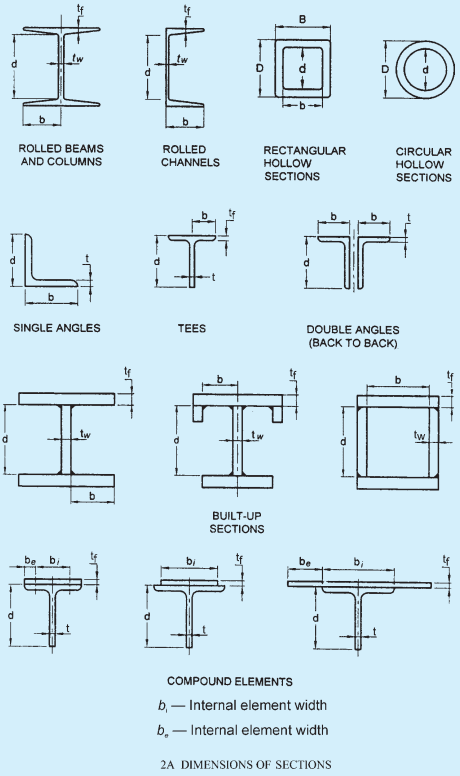
FIG. 2 CLASSIFICATION OF SECTIONS — (Continued)
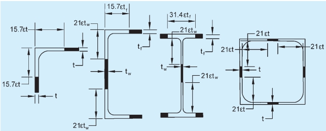
2B EFFECTIVE SECTION OF SLENDER MEMBERS UNDER COMPRESSION, PURE
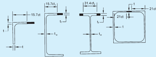
2C EFFECTIVE SECTION OF SLENDER MEMBERS UNDER COMPRESSION, FLEXURAL
FIG. 2 CLASSIFICATION OF SECTIONS
gyration based on the effective section as defined in 9.6.1.