This Part deals with the development control rules and general building requirements to ensure health and safety of the public.
Loading…
Plots/dwelling units when located along a pedestrianized or vehicular ‘cul-de-sac’ road (see Fig. 4).
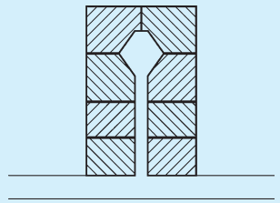
FIG. 4 CUL-DE-SAC CLUSTER
2.28 Density — The residential density expressed in terms of the number of dwelling units per hectare.
NOTE — Where such densities are expressed exclusive of community facilities and provision of open spaces and major roads (excluding incidental open spaces), these will be net residential densities. Where these densities are expressed taking into consideration the required open space provision and community facilities and major roads, these would be gross residential densities at neighbourhood level, sector level or town level, as the case may be. The provision of open spaces and community facilities will depend on the size of the residential community.
Incidental open spaces are mainly open spaces required to be left around and in between two buildings to provide lighting and ventilation.
2.29 Detached Building — A building detached on all sides.
2.30 Development — ‘Development’ with grammatical variations means the carrying out of building, engineering, mining or other operations, in, or over, or under land or water, on the making of any material change, in any building or land, or in the use of any building, land, and includes redevelopment and layout and subdivision of any land; and ‘to develop’ shall be construed accordingly.
2.31 Drain — A conduit, channel or pipe for the carriage of storm water, sewage, waste water or other water borne wastes in a building drainage system.
2.32 Drainage — The removal of any liquid by a system constructed for the purpose.
2.33 Dwelling Unit/Tenement — An independent housing unit with separate facilities for living, cooking and sanitary requirements.
2.34 Escalator — A power driven, inclined, continuous moving stairway used for raising or lowering passengers.
2.35 Exit — A passage, channel or means of egress from any building, storey or floor area to a street or other open space of safety.
2.36 External Faces of Cluster — Building edges facing the cluster open spaces.
2.37 Fire Separation — The distance in metres measured from the external wall of the building concerned to the external wall of any other building on the site, or from other site, or from the opposite side of a street or other public space for the purpose of preventing the spread of fire.
2.38 Floor — The lower surface in a storey on which one normally walks in a building. The general term ‘floor’ unless specifically mentioned otherwise shall not refer to a ‘mezzanine floor’.
2.39 Floor Area Ratio (FAR) — The quotient obtained
by dividing the total covered area (plinth area) on all floors by the area of the plot:
2.40 Gallery — An intermediate floor or platform projecting from a wall of an auditorium or a hall providing extra floor area, additional seating accommodation, etc. It shall also include the structures provided for seating in stadia.
2.41 Garage, Private — A building or a portion thereof designed and used for parking of private owned motor driven or other vehicles.
2.42 Garage, Public — A building or portion thereof, other than a private garage, designed or used for repairing, servicing, hiring, selling or storing or parking motor driven or other vehicles.
2.43 Group Housing — Housing for more than one dwelling unit, where land is owned jointly (as in the case of cooperative societies or the public agencies, such as local authorities or housing boards, etc) and the construction is undertaken by one Agency.
2.44 Group Open Space — Open space within a cluster.
Group open space is neither public open space nor private open space. Each dwelling unit around the cluster open space have a share and right of use in it. The responsibility for maintenance of the same is to be collectively shared by all the dwelling units around.
2.45 Habitable Room — A room occupied or designed for occupancy by one or more persons for study, living, sleeping, eating, kitchen if it is used as a living room, but not including bathrooms, water-closet compartments, laundries, serving and store pantries, corridors, cellars, attics, and spaces that are not used frequently or during extended periods.
2.46 Independent Cluster — Clusters surrounded from all sides by vehicular access roads and/or pedestrian paths (see Fig. 5).
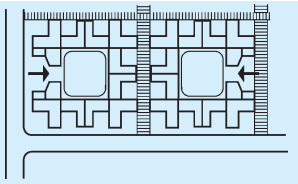
FIG. 5 INDEPENDENT CLUSTER
2.47 Interlocking Cluster — Clusters when joined at back and on sides with at least one side of a cluster common and having some dwelling units opening onto or having access from the adjacent clusters.
Dwelling units in such clusters should have at least two sides open to external open space. Houses in an interlocking cluster may have access, ventilation and light from the adjacent cluster and should also cater for future growth (see Fig. 6).

FIG. 6 INTERLOCKING CLUSTER
2.48 Internal Faces of Cluster — Building edges facing the adjacent cluster open space (as in case of interlocking cluster) of the surrounding pedestrian paths or vehicular access roads.
2.49 Ledge or Tand — A shelf-like projection, supported in any manner whatsoever, except by means of vertical supports within a room itself but not having projection wider than 1 m.
2.50 Lift — An appliance designed to transport persons or materials between two or more levels in a vertical or substantially vertical direction by means of a guided car or platform. The word ‘elevator’ is also synonymously used for ‘lift’.
2.51 Loft — A structure providing intermediate storage space in between two floors with a maximum height of 1.5 m, without having a permanent access.
2.52 Master Plan — A master plan formulated under any relevant act (Town and Country Planning or Development Act or Municipal Act) for any town, approved and notified by the State Government.
2.53 Mezzanine Floor — An intermediate floor between two floors of any storey forming an integral part of floor below.
2.54 Occupancy or Use Group — The principal occupancy for which a building or a part of a building is used or intended to be used; for the purposes of classification of a building according to occupancy; an occupancy shall be deemed to include subsidiary occupancies which are contingent upon it.
2.55 Occupancy, Mixed — A multiple occupancy where the occupancies are intermingled.
2.56 Open Clusters — Clusters where cluster open spaces are linked to form a continuous open space (see Fig. 7).
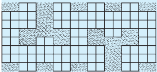
FIG. 7 OPEN CLUSTER
2.57 Open Space — An area, forming an integral part of the plot, left open to the sky.
NOTE — The open space shall be the minimum distance measured between the front, rear and side of the building and the respective plot boundaries.
2.58 Open Space, Front — An open space across the front of a plot between the building line and front boundary of the plot.
2.59 Open Space, Rear — An open space across the rear of a plot between the rear of the building and the rear boundary of the plot.
2.60 Open Space, Side — An open space across the side of the plot between the side of the building and the side boundary of the plot.
2.61 Owner — A person, a group of persons or a body having a legal interest in land and/or building thereon. This includes free holders, leaseholders or those holding a sublease, who will have a legal right to occupation and have liabilities in respect of safety or building condition.
In case of lease or sublease holders, as far as ownership with respect to the structure is concerned, the structure of a flat or structure on a plot belongs to the allottee/lessee till the allotment/lease subsists.
Note — For the purpose of the Code, the word ‘owner’ will also cover the generally understood terms like ‘client’, ‘user’, etc.
2.62 Parapet — A low wall or railing built along the edge of a roof or floor.
2.63 Parking Space — An area enclosed or unenclosed, covered or open, sufficient in size to park vehicles, together with a drive-way connecting the parking space with a street or alley and permitting ingress and egress of the vehicles.
2.64 Partition — An interior non-load bearing barrier, one storey or part-storey in height.
2.65 Plinth — The portion of a structure between the surface of the surrounding ground and surface of the floor, immediately above the ground.
2.66 Plinth Area — The built up covered area measured at the floor level of the basement or of any storey {see accepted standard [3(1)]}.
2.67 Porch — A covered structure supported on pillars or otherwise for the purpose of pedestrian or vehicular approach to a building.
2.68 Road — See ‘Street’.
2.69 Road Line — See ‘Street Line’.
2.70 Room Height — The vertical distance measured from the finished floor surface to the finished ceiling surface. Where a finished ceiling is not provided, the underside of the joists or beams or tie beams shall determine the upper point of measurement.
2.71 Row Housing/Row Type Building — A row of buildings, with only front, rear and interior open spaces, where applicable.
2.72 Semi-Detached Building — A building detached on three sides.
2.73 Service Road/Lane — A road/lane provided adjacent to a plot(s) for access or service purposes as the case may be.
2.74 Set-Back Line — A line usually parallel to the plot boundaries and laid down in each case by the Authority, beyond which nothing may be constructed towards the plot boundaries.
2.75 Site (Plot) — A parcel (piece) of land enclosed by definite boundaries.
2.76 Site, Corner — A site at the junctions of and fronting on two or more intersecting streets.
2.77 Site, Depth of — The mean horizontal distance between the front and rear site boundaries.
2.78 Site, Double Frontage — A site, having a frontage on two streets, other than a corner plot.
2.79 Site, Interior or Tandem — A site access to which is by a passage from a street whether such passage forms part of the site or not.
2.80 Staircover (or Mumty) — A structure with a roof over a staircase and its landing built to enclose only the stairs for the purpose of providing protection from weather and not used for human habitation.
2.81 Storey — The portion of a building included between the surface of any floor and the surface of the floor next above it, or if there be no floor above it, then the space between any floor and the ceiling next above it.
2.82 Storey, Topmost — The uppermost storey in a
building whether constructed wholly or partly on the roof.
2.83 Street — Any means of access, namely, highway, street, lane, pathway, alley, stairway, passageway, carriageway, footway, square, place or bridge, whether a thoroughfare or not, over which the public have a right of passage or access or have passed and had access uninterruptedly for a specified period, whether existing or proposed in any scheme, and includes all bunds, channels, ditches, storm-water drains, culverts, footpaths, sidewalks, traffic islands, roadside trees and hedges, retaining walls, fences, barriers and railings within the street lines.
2.84 Street Level or Grade — The officially established elevation or grade of the central line of the street upon which a plot fronts and if there is no officially established grade, the existing grade of the street at its mid-point.
2.85 Street Line — The line defining the side limits of a street.
2.86 To Erect — To erect a building means,
a) to erect a new building on any site whether previously built upon or not; and
b) to re-erect any building of which portions above the plinth level have been pull down, burnt or destroyed.
2.87 Tower-Like Structures — Structures shall be deemed to be tower-like structures when the height of the tower-like portion is at least twice the height of the broader base at ground level.
2.88 Verandah — A covered area with at least one side open to the outside with the exception of 1 m high parapet on the upper floors to be provided on the open side.
2.89 Volume to Plot Area Ratio (VPR) — The ratio of volume of building measured in cubic metre to the area of the plot measured in square metre, and expressed in metre.
2.90 Water Closet— A water flushed plumbing fixture designed to receive human excrement directly from the user of the fixture. The term is used sometimes to designate the room or compartment in which the fixture is placed.
2.91 Window — An opening to the outside other than a door, which provides all or part of the required natural light or ventilation or both to an interior space.
For the purpose of this Part, the following definitions shall apply.
2.1 Access — A clear approach to a plot or a building.
2.2 Accessory Use — Any use of the premises subordinate to the principal use and customarily incidental to the principal use.
2.3 Alteration — A change from one occupancy to another, or a structural change, such as an addition to the area or height, or the removal of part of a building, or any change to the structure, such as the construction of, cutting into or removal of any wall, partition, column, beam, joist, floor (including a mezzanine floor) or other support, or a change to or closing of any required means of ingress or egress or a change to the fixtures or equipment.
2.4 Approved — Approved by the Authority having jurisdiction.
2.5 Authority Having Jurisdiction — The Authority which has been created by a statute and which for the purpose of administering the Code/Part may authorize a committee or an official to act on its behalf; hereinafter called the ‘Authority’.
2.6 Back-to-Back Cluster — Clusters when joined back to back and/or on sides (see Fig. 1).
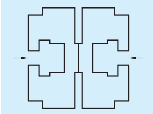
FIG. 1 BACK TO BACK CLUSTER
2.7 Balcony — A horizontal projection, with a handrail or balustrade or a parapet, to serve as passage or sitting out place.
2.8 Basement or Cellar — The lower storey of a building, below or partly below ground level.
2.9 Building — Any structure for whatsoever purpose and of whatsoever materials constructed and every part thereof, whether used as human habitation or not and includes foundation, plinth, walls, floors, roofs, chimneys, plumbing and building services, fixed platforms, Verandah, balcony, cornice or projection, part of a building or anything affixed thereto or any wall enclosing or intended to enclose any land or space and signs and outdoor display structures. Tents, Shamianahs, tarpaulin shelters, etc, erected for temporary and ceremonial occasions with the permission of the Authority shall not be considered as building.
2.10 Building, Height of — The vertical distance measured in the case of flat roofs, from the average level of the ground around and contiguous to the building or as decided by the Authority to the terrace of last livable floor of the building adjacent to the external walls; and in the case of pitched roofs, up to the point where the external surface of the outer wall intersects the finished surface of the sloping roof; and in the case of gables facing the road, the mid-point between the eaves level and the ridge. Architectural features serving no other function except that of decoration shall be excluded for the purpose of measuring heights. See 9.4.2.1.
2.11 Building Envelope — The horizontal spatial limits up to which a building may be permitted to be constructed on a plot.
2.12 Building Line — The line up to which the plinth of a building adjoining a street or an extension of a street or on a future street may lawfully extend. It includes the lines prescribed, if any, in any scheme. The building line may change from time to time as decided by the Authority.
2.13 Cabin — A non-residential enclosure constructed of non-load bearing partition.
2.14 Canopy — A projection over any entrance.
2.15 Carpet Area — The covered area of the usable rooms at any floor level (excluding the area of the wall) {see accepted standard [3(1)]}.
2.16 Chhajja — A sloping or horizontal structural overhang usually provided over openings on external walls to provide protection from sun and rain.
2.17 Chimney — An upright shaft containing one or more flues provided for the conveyance to the outer air of any product of combustion resulting from the operation of heat producing appliance or equipment employing solid, liquid or gaseous fuel.
2.18 Chowk or Courtyard — A space permanently open to the sky, enclosed fully or partially by building and may be at ground level or any other level within or adjacent to a building.
2.19 Chowk, Inner — A chowk enclosed on all sides.
2.20 Chowk, Outer — A chowk one of whose sides is not enclosed.
2.21 Closed Clusters —Clusters with only one common entry into cluster open space (see Fig. 2).
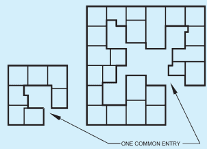
FIG. 2 CLOSED CLUSTER
2.22 Cluster — Plots or dwelling units or housing grouped around an open space (see Fig. 3). Ideally housing cluster should not be very large. In ground and one storeyed structures not more than 20 houses should be grouped in a cluster. Clusters with more dwelling units will create problems in identity, encroachments and of maintenance.
2.23 Cluster Court Town House — A dwelling in a cluster plot having 100 percent or nearly 100 percent ground coverage with vertical expansion, generally limited to one floor only and meant for self use.
2.24 Cluster Plot — Plot in a cluster.
2.25 Cooking Alcove — A cooking space having direct access from the main room without any inter-communicating door.
2.26 Covered Area — Ground area covered by the building immediately above the plinth level. The area covered by the following in the open spaces is excluded
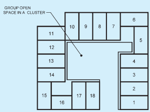
FIG. 3 CLUSTER
from covered area (see Table 5):
a) Garden, rockery, well and well structures, plant nursery, water pool, swimming pool (if uncovered), platform round a tree, tank, fountain, bench, Chabutra with open top and unenclosed on sides by walls and the like;
b) Drainage culvert, conduit, catch-pit, gully pit, chamber, gutter and the like;
c) Compound wall, gate, unstoreyed porch and portico, canopy, slide, swing, uncovered staircase, ramps areas covered by Chhajja and the like; and
d) Watchmen's booth, pump house, garbage shaft, electric cabin or sub-stations, and such other utility structures meant for the services of the building under consideration.
NOTE — For the purpose of this Part, covered area equals the plot area minus the area due for open spaces.
The land use classification may be as indicated below:
| Sl No. | Level 1 | Level 2 | ||||||
| N¹⁾ | A-N²⁾ | Use Category | Colour Code3),4) | Colour Code Description | N | A-N | Use Zone | |
| (1) | (2) | (3) | (4) | (5) | (6) | (7) | (8) | (9) |
| i) | 1 | R | Residential | Yellow | 11 | R-1 | Primary residential zone | |
| 12 | R-2 | Unplanned/Informal residential zone | ||||||
| ii) | 2 | C | Commercial | Red | 21 | C-1 | Retail shopping zone | |
| 22 | C-2 | General business and commercial district centres | ||||||
| 23 | C-3 | Wholesale, godowns, warehousing/regulated markets | ||||||
| 24 | C-4 | Service sector | ||||||
| 25 | C-5 | Regulated/Informal/Weekly markets | ||||||
| iii) | 3 | I | Industry | Purple | 31 | I-1 | Service and light industry | |
| 32 | I-2 | Extensive and heavy industry | ||||||
| 33 | I-3 | Special industrial zone - Hazardous, noxious and chemical | ||||||
| iv) | 4 | PS | Public and semi-public | Dark blue | 41 | PS-1 | Govt/Semi Govt/Public offices | |
| 42 | PS-2 | Govt land (use undetermined) | ||||||
| 43 | PS-3 | Police headquarter/Station, police line | ||||||
| 44 | PS-4 | Educational and research | ||||||
| 45 | PS-5 | Medical and health | ||||||
| 46 | PS-6 | Social, cultural and religious (including cremation and burial grounds) | ||||||
| 47 | PS-7 | Utilities and services | ||||||
| v) | 5 | M | Mixed use | Light yellow background with vertical hatching in black | 51 | M-1 | Mixed industrial use zone | |
| 52 | M-2 | Mixed residential zone | ||||||
| 53 | M-3 | Mixed commercial zone | ||||||
| vi) | 6 | P | Recreational | Light green | 61 | P-1 | Playgrounds/Stadium/Sports complex | |
| 62 | P-2 | Parks and gardens – Public open spaces | ||||||
| 63 | P-3 | Multi-open space (Maidan) | ||||||
²⁾ Alpha-numeric code.
¹⁾ Numeric code.
| (1) | (2) | (3) | (4) | (5) | (6) | (7) | (8) | (9) |
| vii) | 7 | T | Transportation and communication | Brown/Grey⁵⁾ | 71 | T-1 | Roads/Bus rapid transit system (BRTS) | |
| 72 | T-2 | Railways/Mass rapid transit system (MRTS) | ||||||
| 73 | T-3 | Airport | ||||||
| 74 | T-4 | Seaports and dockyards | ||||||
| 75 | T-5 | Bus depots/Truck terminals and freight complexes | ||||||
| 76 | T-6 | Transmission and communication | ||||||
| viii) | 8 | A | Primary activity | Dark green | 81 | PA-1 | Agriculture | |
| 82 | PA-2 | Forest and horticulture | ||||||
| 83 | PA-3 | Poultry and dairy farming | ||||||
| 84 | PA-4 | Rural settlements | ||||||
| 85 | PA-5 | Brick kiln and extractive areas | ||||||
| 86 | PA-6 | Others (Fishing, pottery, etc) | ||||||
| ix) | 9 | E | Protective and undevelopable use zone | Light blue | 91 | E-1 | Water bodies | |
| 92 | E-2 | Special recreation zone/Protective areas, such as sanctuaries/reserve forests and eco-sensitive zone | ||||||
| 93 | E-3 | Undevelopable use zone | ||||||
| x) | 10 | S | Special area | Pink | 101 | S-1 | Old built-up (Core) area | |
| 102 | S-2 | Heritage and conservation areas | ||||||
| 103 | S-3 | Scenic value areas | ||||||
| 104 | S-4 | Government restricted area (such as defence) | ||||||
| 105 | S-5 | Other uses/spot zone (see Note 5) |
NOTES
1 Overall, there could be 43 use zones at the development plan level within 10 land use categories at the perspective plan level as given in the above table.
2 Areas of informal activities may be identified in the above land use categories at level 2 for 1 to 7 level 1 use zones only.
3 Mixed use zone shall be identified at the development plan level, having dominant use and mixed use.
4 Use permissions for different activities, as specified in the next section on simplified use zone regulations may be provided at the project/action plan level or with the approval of the Statutory Authority as the case may be.
5 The process of changing/relaxing/modifying land use of part or ‘spot’ of a ‘zone’ in a particular land use is termed as ‘Spot Zoning’. Spot zoning may be done for comparatively smaller area in a particular land use zone in such a way that it does not affect the overall development plan.
6 Use zone regulations for the use permissibility (from the suggestive list) could be decided by the town planner depending upon the requirement/feasibility.
7 Appropriate code in terms of both numerical and alphabetic (letter) are provided to facilitate the reference and to have a simplified procedure to follow.
³⁾ This colour code is for Level 1 land uses.
⁴⁾ For subsequent levels of land uses different shades of Level 1 land use colour may be used along with relevant alpha-numeric code for clarity.
⁵⁾ For transportation and communication facilities, brown colour, and for roads, grey colour may be used. If so decided by the planning agency, different shades of grey may be used for both roads and facilities.
3.2 The various building uses and occupancies (see 7) permitted on the various zones shall be as given in the Master Plan of the town/city concerned.
Where the use of buildings or premises is not specifically designated on the Development/Master Plan or in the absence of Development Plan, shall be in conformity with the zone in which they fall.
Where the use of a site is specifically designated on the Development/Master Plan, it shall be used only for the purpose so designated.
No plot shall be put to any use, occupancy or premises other than the uses identified in 3.1, except with the prior approval of the Authority.
Buildings shall be so planned, designed and constructed as to ensure fire safety and this shall be done as per Part 4 ‘Fire and Life Safety’ of the Code.
3.7.1 Transferable development rights (TDR) is a compensation, in the form of floor area ratio (FAR) or development right, which shall entitle the owner for construction of built-up area, as per applicable regulations, on designated sites. The FAR credit shall be issued, in a certificate called as development right certificate (DRC). The DRC is transferrable in full or part thereof.
The development right certificate (DRC) shall be issued by the local body or the competent authority as per regulations and shall contain the following information:
a) Built-up area or FAR credit to which the owner is entitled;
b) Place and usage zone from which the DRC is generated (originating plot);
c) Place where the FAR credit shall be used (receiving plot); and
d) Details of development rights transferred and remaining.
TDR may be granted for,
a) Lands earmarked for various public purposes including road widening, which are subjected to acquisition, and are proposed in the plan or regulations prepared under the applicable town planning/municipal or any other legislation;
b) Development or construction of the amenity on the reserved land;
c) Heritage structure or precinct under the provision of development control regulations or any other applicable regulations;
d) In-lieu of constructing housing for slum dwellers, slum redevelopment, disused mill sites, etc; and
e) Purposes as may be notified by the Government as per notification.
Accommodation reservation (AR) is a planning tool for development of public amenities reserved in a redevelopment plan wherein local authority is not required to acquire the land by incurring expenditure on payment of compensation. In case of AR, the owner of land earmarked as public amenity, in the redevelopment plan, shall be permitted to develop his land, using full permissible FAR on the plot, subject to handing over the built-up area for the proposed use to the local body/Authority, free of all encumbrances, in lieu of full permissible FAR granted to him. The area utilized for the amenity shall not form part of FAR calculation.
In any layout or sub-division of land measuring 0.3 ha or more in residential and commercial zones, the community open spaces shall be reserved for recreational purposes which shall as far as possible
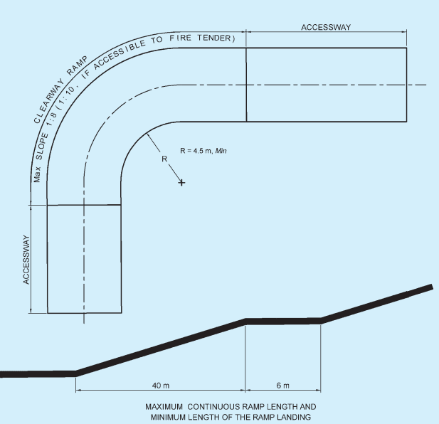
MINIMUM CLEAR RAMP WIDTH, m
| ONE WAY | TWO WAY | |
| LMV | 3.0 | 6.0 |
| LCV | 4.5 | 9.0 |
| HMV | 6.0 | 12.0 |
| FIRE TENDER | 7.5 | |
8B RAMPS FOR PODIUM
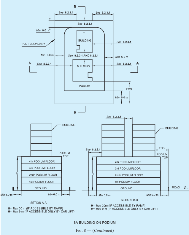
FIG. 8 BUILDINGS ON PODIUM AND THEIR RAMPS
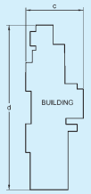
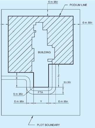
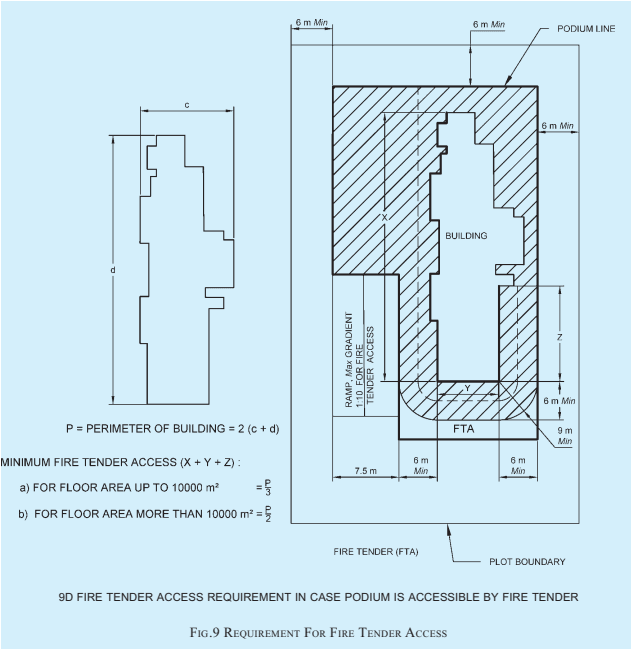
FIRE TENDER ACCESS (FTA)
9A EMERGENCY VEHICLE ACCESS REQUIREMENT IN CASE PODIUM IS NOT ACCESSIBLE BY FIRE TENDER
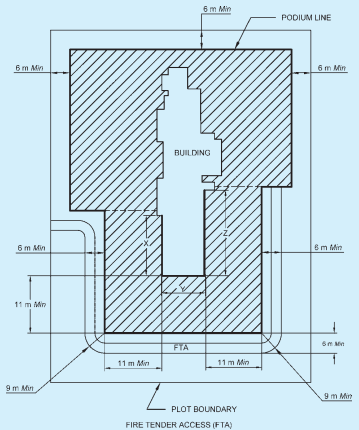
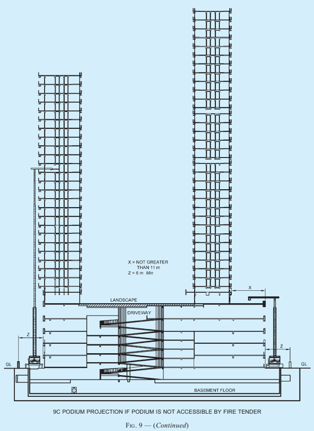
9B EXTENT OF PODIUM PROJECTION ALLOWED BEYOND BUILDING ON SIDE HAVING FIRE TNEDER ACCESS (IF PODIUM IS NOT ACCESSIBLE BY FIRE TENDER)
FIG. 9 — (Continued)
be provided in one place or planned out for the use of the community in clusters or pockets.
5.1.1 The community open spaces shall be provided catering to the needs of area of layout, population for which the layout is planned and the category of dwelling units. The following minimum provision shall be made:
a) 15 percent of the area of the layout, or
b) 0.3 to 0.4 ha/1 000 persons; for low income housing, the open spaces shall be 0.3 ha/1 000 persons.
5.2 No recreational space shall generally be less than 450m².
5.2.1 The minimum average dimension of such recreational space shall be not less than 7.5m; if the average width of such recreational space is less
than 24 m, the length thereof shall not exceed 2.5 times the average width. However, depending on the configuration of the site, commonly open spaces of different shapes may be permitted by the Authority, as long as the open spaces provided serve the needs of the immediate community contiguous to the open spaces.
5.2.2 In such recreational spaces, a single storeyed structure as pavilion or gymnasia up to 25m² in area may be permitted; such area may be excluded from FAR calculations.
5.3 Each recreational area and the structure on it shall have an independent means of access. Independent means of access may not be insisted upon if recreational space is approachable directly from every building in the layout. Further, the building line shall be at least 3 m away from the boundary of recreational open space.
In the case of sub-division of land in industrial zones of area 0.8 hectare or more, 5 percent of the total area shall be reserved as amenity open space which shall also serve as a general parking space; when such amenity open space exceeds 1 500 m² , the excess area could be utilized for the construction of buildings for banks, canteens, welfare centers and such other common purposes considered necessary for the industrial user, as approved by the Authority.
5.4.1 In all industrial plots measuring 1000m² or more in area, 10 percent of the total area shall be provided
as an amenity open space to a maximum of 2 500 m² . Such an amenity open space shall have a means of access and shall be so located that it could be conveniently utilized as such by the persons working in the industry.
6.1 No building shall be constructed on any site, on any part of which there is deposited refuse, excreta or other offensive matter objectionable to the Authority, until such refuse has been removed therefrom and the site has been prepared or left in a manner suitable for building purposes to the satisfaction to the Authority.
Wherever the dampness of a site or the nature of the soil renders such precautions necessary, the ground surface of the site between the walls of any building erected thereon shall be rendered damp-proof to the satisfaction of the Authority.
Any land passage or other area within the curtilage of a building shall be effectively drained by surface water drains or other means.
6.3.1 The written approval of the Authority shall be obtained for connecting any subsoil or surface water drain to a sewer.
An overhead line shall not cross an existing building as far as possible and no building shall be constructed under an existing overhead line. No accessible point from any Verandah, balcony, or the like shall be allowed to be erected or re-erected or any additions or alterations made to a building not having the following minimum clearances from an overhead electric supply line, in accordance with the current Central Electricity Authority (Measures Relating to Safety and Electric Supply) Regulations, 2010 as amended from time to time:
a) Clearance of buildings from lines of voltages and service lines not exceeding 650V
An overhead line shall not cross over an existing building as far as possible and no building shall be constructed under an existing overhead line.
Where an overhead line of voltage not exceeding 650 V passes above or adjacent to or terminates on any building, the following minimum clearances from any accessible point, on the basis of maximum sag, shall be observed:
i) For any flat roof, open balcony, Verandah roof and lean-to-roof:
a) where the line passes above the building, a vertical clearance of 2.5 m from the highest point, and
b) when the line passes adjacent to the building, a horizontal clearance of 1.2 m from the nearest point, and
ii) For pitched roof:
a) where the line passes above the building, a vertical clearance of 2.5m immediately under the line, and
b) when the line passes adjacent to the building, a horizontal clearance of 1.2m.
The horizontal clearance shall be measured when the line is at a maximum deflection from the vertical due to wind pressure.
Any conductor so situated as to have a clearance less than that specified above shall be adequately insulated and shall be attached at suitable intervals to a bare earthed bearer wire having a breaking strength of not less than 350 kg.
b) Clearances from buildings of lines of voltages exceeding 650 V
no building shall be constructed under an existing overhead line.
i) For lines of : 3.7 m upto and voltages including 33 kV; exceeding and 650 V
ii) For lines of : 3.7 m plus 0.30 m voltages for every additional 33 kV or part thereof. exceeding 33 kV
The horizontal clearance between the nearest conductor and any part of such building shall, on the basis of maximum deflection due to wind pressure, be not less than:
i) For lines of : 1.2 m voltages exceeding 650 V and up to and including 11 kV
ii) For lines of : 2.0 m voltages exceeding 11 kV and up to and including 33 kV
iii) For lines of : 2.0 m plus voltages exceeding 0.3 m for every additional 33 kV or part thereof
| Sl No. | d.c.Voltage | Vertical Clearance | Horizontal Clearance |
|---|---|---|---|
| kV | m | m | |
| (1) | (2) | (3) | (4) |
| i) | 100 | 4.6 | 2.9 |
| ii) | 200 | 5.8 | 4.1 |
| iii) | 300 | 7.0 | 5.3 |
| iv) | 400 | 7.0 | 6.2 |
| v) | 500 | 9.1 | 7.4 |
| vi) | 600 | 10.3 | 8.6 |
| vii) | 800 | 12.4 | 10.7 |
Distance of site from the normal edge of water course/area may be specified by the Authority, keeping in view the normal maximum flood/tide level.
Each plot shall have a minimum size/frontage corresponding to the type of development as given below:
| SlNo.(1) | Type of Development(2) | Plot Size m² (3) | Frontagem(4) |
| i) | Detached building | Above 250 | above 12 |
| ii) | Semi-detachedbuilding | 125-250 | 8 to 12 |
| iii) | Row type building | 50-125 | 4.5 to 8 |
| NOTE — For low income housing,see 14. | |||
6.6.1.1 The minimum size of the site for group housing development shall be as given in the Master Plan and local development control rules.
The size of the plot shall not be less than 300m² and its width shall not be less than 15m.
The minimum size of plots for buildings for other uses not covered under 5.5 shall be as decided by the Authority. Various requirements with respect to cinema buildings shall be in accordance with the good practice [3(2)].
4.1 Every building/plot shall abut on a public/private means of access like streets/roads duly formed.
4.2 Every person who erects a building shall not at any time erect or cause or permit to erect any building which in any way encroaches upon or diminishes the area set apart as means of access required in the Code. No buildings shall be erected so as to deprive any other building of the means of access.
The residential plots shall abut on a public means of access like street/road. Plots which do not abut on a street/road shall abut/front on a means of access, the width and other requirements of which shall be as given in Table 1.
| Sl No. | Width of Means of Access | Length of Means of AccessMax |
| m | m | |
| (1) | (2) | (3) |
| i) | 6.0 | 75 |
| ii) | 7.5 | 150 |
| iii) | 9.0 | 250 |
| iv) | 12.0 | 400 |
| v) | 18.0 | 1 000 |
| vi) | 24.0 | above 1 000 |
| NOTE — If the development is only on one side of the means of access, the prescribed widths may be reduced by 1m in each case. | ||
In no case, development on plots shall be permitted unless it is accessible by a public street of width not less than 6 m.
For all assembly buildings like, theatres, cinema houses, assembly halls, stadia; educational buildings; markets, hospitals; industrial buildings and other buildings which attract large crowd, the means of access shall not be less than the following:
| Sl No. | Width of Means of Access m | Length of Means of Access m |
|---|---|---|
| i) | 12.0 | 200 |
| ii) | 15.0 | 400 |
| iii) | 18.0 | 600 |
| iv) | 24.0 | above 600 |
Further, in no case shall the means of access be lesser in width than the internal accessways in layouts and subdivision.
4.3.2.1.1 Footpath should be normally designed for a pedestrian Level of Service (LOS) B, thereby providing wide pedestrian facilities for safe, pleasant and comfortable walking. Under resource constraint, LOS C may be adopted for deciding the width of footpath mentioned in Table 2. The width of footpaths depends upon the expected pedestrian traffic and may be fixed with the help of the following norms subject to not being less than 1.8 m.
| Sl No. | Width of Foothpath | Design Flow in Number of Persons Per Hour | |||
| In Both Directions | All in One Direction | ||||
| m | LOS B(3) | LOS C(4) | LOS B(5) | LOS C(6) | |
| (1) | (2) | ||||
| i) | 1.8 | 1 350 | 1 890 | 2 025 | 2 835 |
| ii) | 2.0 | 1 800 | 2 520 | 2 700 | 3 780 |
| iii) | 2.5 | 2 250 | 3 150 | 3 375 | 4 725 |
| iv) | 3.0 | 2 700 | 3 780 | 4 050 | 5 670 |
| v) | 3.5 | 3 150 | 4 410 | 4 725 | 6 615 |
| vi) | 4.0 | 3 600 | 5 040 | 5 400 | 7 560 |
The land use adjacent to roads significantly influences generation of pedestrian traffic. Recommended width of footpath along various land uses are given in Table 3.
| Sl No. | Description | Width |
| m | ||
| (1) | (2) | (3) |
| i) | Minimum free walkway width and residential/mixed use areas | 1.8 |
| ii) | Commercial/Mixed use areas | 2.5 |
| iii) | Shopping frontages | 3.5 to 4.5 |
| iv) | Bus stops | 3 |
No premises other than highway amenities like petrol pumps, motels, etc, shall have an access direct from highways and such other roads not less than 52 m in width, which the Authority with the approval of the highway authority shall specify from time to time. For all other buildings, the access to the plot from the highway shall be only through a service road/lane as per the stipulation of the highway authority. The Authority shall maintain a register of such roads which shall be open to public inspection at all times during office hours. The portion of such roads on which direct access may be permitted shall be as identified in the Development Plan. However, in the case of existing development on highways/other roads referred to above, the operation of this clause shall be exempted. These provisions shall, however, be subject to the provisions of the relevant State Highway Act, and The National Highway Act, 1956.
4.6 For high rise buildings and special buildings (see Part 4 ‘Fire and Life Safety’ of the Code), the following additional provisions of means of access shall be ensured:
a) The width of the main street on which the building abuts shall not be less than 12 m and one end of this street shall join another street not less than 12 m in width.
b) The road shall not terminate in a dead end; except in the case of residential building, up to a height of 30 m.
c) The approach to the building and open spaces on all its sides shall be not less than 6 m in width, and a turning radius of minimum 9 m shall be provided for fire tender movement of fire tenders weighing up to 45 t. The same shall be hard surface capable of taking the mass of fire tender, weighing up to 45 t minimum. For heavier fire tenders, the minimum width, turning radius and the hard surface capable of taking the fire tender loads shall be as per the requirement laid down by the Fire Department. The layout for the open space for fire tender movement shall be done in consultation with the Chief Fire Officer of the city, which shall be kept free of obstructions and shall be motorable. The compulsory open spaces around the building shall not be used for parking.
d) The main entrance to the plot shall be of adequate width to allow easy access to the fire engine and in no case shall it measure less than 6 m. The entrance gate shall fold back against the compound wall of the premises, thus leaving the exterior accessway within the plot free for movement of fire tender. If the main entrance at the boundary wall is built over, the minimum clearance shall be 4.5 m.
4.6.1.1 Podium is a horizontal projection (platform) extending beyond the building footprint on one or more sides, and may consist of one or more levels (see Fig. 8A).
Podium may be used for the following purposes:
a) Parking of vehicles — When used for parking, one WC, two urinals and two washbasins for every 500 cars or part thereof, shall be provided on each podium floor. At least one accessible toilet complying with the requirements given in B-9 shall be provided preferably near the accessible parking.
For intersection junctions of roads meeting at right angles as well as other than right angles, the rounding off or cut off or splay or similar treatment shall be done, to the approval of the Authority, depending upon the width of roads, the traffic generated, the sighting angle, etc, to provide clear sight distance.
4.9 The building line shall be set back at least 3m from internal means of access in a layout of buildings in a plot subject to provisions of 8.2.1.
BUREAU OF INDIAN STANDARDS
This Code (Part 3) covers development control rules, including such aspects as subdivision and layout rules, land use classifications, open spaces, area and height limitations, means of access, and parking spaces. This Part also covers the general building requirements, including those of various parts of buildings.
It is expected that for proper coordination and enforcement of the development control rules and general building requirements, the departments concerned, namely, the town and country planning department, urban development authority, urban local body and the building department, will coordinate the total development and building activity at both organizational and technical levels.
Particular attention is invited to Table 5 on floor area ratio (FAR) limitations. It is emphasized that the floor area of a single storey building is limited in absolute terms by the type of construction and occupancy class. Also, the absolute floor areas for different types of construction and different occupancies have a definite ratio among them. The ratios as recommended in the American Iron and Steel Institute Publication of 1961 ‘Fire protection through modern building codes’ have been generally adopted in this Part and Table 5 has been developed on this basis. This, Table 5 is repeated in Part 4 ‘Fire and Life Safety’ of the Code also, for convenience of reading.
Limitation of areas and heights of buildings are regulated by specifying floor area ratio (FAR) or floor space index (FSI) and ground coverage. The significance of the contribution of different types of construction giving different fire resistances has not been taken cognizance of in specifying FAR for different occupancies, in the present development control rules and municipal byelaws of the country. Table 5, therefore, gives the comparative ratios of FAR between types of buildings and occupancy classes and these have been specified mainly from the fire protection aspect of buildings. To arrive at the actual FAR for different buildings coming up in different areas, the Authority should further modify them, by taking into consideration other aspects like population density of any area, parking facilities required, the traffic load (road width) and the services available. The heights of buildings shall also be regulated, keeping in view the local fire fighting facilities.
In some state byelaws, the FAR (or FSI) has been expressed in the form of percentage. However, the Committee responsible for the preparation of this Code is of the opinion that, it being a ratio should be expressed only in the form of a ratio, as done in this Part.
It is particularly to be borne in mind by the Authority that the ratios are definitive and it may assess the particular FAR for a type of construction and for an occupancy and establish a new table, but retaining the comparative ratios as given in Table 5.
Keeping in view the enormous problems faced by the country with regard to the ever increasing squatter settlements/pavement dwellers in urban areas (cities of all sizes), it is imperative that all the urban local bodies and urban development authorities sooner or later evolve schemes for their rehabilitation. The resources are meagre and the problems are enormous. There has been a tendency on the part of a number of urban development authorities/urban local bodies to link space norms with affordability. Affordability is an important criterion but at the same time a public agency may not ignore the basic minimum needs of the family to be housed (including the mental, physical and social health of the marginalized groups, which is linked with shelter). The urban local bodies shall have to evolve appropriate policies for their integration with the overall development process and generate/allocate resources and more importantly adopt a planning process, which are people friendly and inclusive. Therefore, keeping in view the needs of low income housing, to cater to Economically Weaker Sections of Society (EWS) and Low Income Group (LIG), the requirements on planning, design of layout/shelter have been rationalized and the same are provided in this Part. This information is based on the provisions of IS 8888 (Part 1):1993 'Guide for requirements of low income housing: Part 1 Urban areas (first revision)'.
It is important that the fruits of development are equally shared by all cross-section of the society irrespective of their age and abilities. This Code therefore covered provisions for buildings and built environment to ensure a barrier-free
environment for elders and persons with disabilities. The goal of barrier free design is to provide an environment that supports the independent functioning of individuals so that they can participate without assistance, in everyday activities. It has been intended to progressively update these provisions and make the same more effective and elaborate based on experience gained with the implementation of the Code and feedback received from stakeholders. As a conscious decision, opportunity has been taken in this revision of the Code to further mainstream the issue of barrier free environment by covering the requirements at greater length. The concept of universal design has also been included herein that promotes the usability of built environment by all without discrimination. It is worthwhile to note that The Persons with Disabilities (Equal Opportunities, Protection of Rights and Full Participation) Act, 1995 in its Chapter VIII ‘Non-Discrimination’, Section 44 to 46 mandates accessibility in public buildings and transportation systems. National policy for persons with disabilities also emphasizes the role of barrier-free environment as one that enables people with disabilities to move about safely and freely, and use the facilities within the built environment. Therefore, to the maximum extent possible, buildings/places/transportation systems for public use should be made barrier free. India has also signed and ratified the UN Convention on Rights of Persons with Disabilities that casts an obligation on the member states in its Article 9‘Accessibility’, to enable persons with disabilities to live independently and participate fully in all aspects of life.
Further, city development process would need a dynamic approach to take care of urban renewal and also development needs in dense core areas of the cities. Innovative approaches in planning and design with participatory models of public private-people's partnership become necessary to solve the emerging development needs. With this in view, many city development authorities have evolved innovative planning and development tools like transferable development rights (TDR) where the developer would receive a portion of the development rights in a new location, keeping in view the constraints in the existing land area and the development potential. Such development rights may be transferred into outskirts or new developed areas where land availability is assured. This would encourage the professionals and developers to participate in urban renewal and at the same time ensure that the developments in both the inner core areas and new areas take place in a planned manner. The TDR concept should be increasingly encouraged by the authority dealing with urban renewal, redevelopment projects including housing and redevelopment projects for slum dwellers.
Transit oriented development (TOD), as a concept, integrates land uses and mass transportation such as bus rapid transit (BRT) and rail based transit like metro-rail, mono-rail, light-rail, ring-rail, etc. The basic objective is to plan cities in a manner where people conveniently walk and use public transport for most of their trips and, thus, reduce dependence on private mode and provide benefits to the city which include reduction in congestion, delays and accidents on roads; reduction of pollution caused by automobiles; and improvement in liveability, mobility and convenience of the citizens. TOD makes city compact and increases its efficiency and functioning. The TOD is desirable as it, (a) reduces/discourages private vehicle dependency and induces public transport use though planning, designing, policy measures and enforcement; and (b) provides easy access to public transport, within walking distance, to a majority of people, through densification and enhanced connectivity.
Some of the planning and design principles applied to create TOD include creation of,
a) pedestrian and non-motorized transport friendly environment;
b) efficient public and para-transport system supporting the transit system;
c) multi-modal interchange and street connectivity;
d) mixed land uses and appropriate intensity of development; and
e) well designed and integrated parking thus requiring reduced parking requirements in comparison to the norms given in this Part.
TOD concept may be suitable for all newly planned green field cities. However, it can also be applied to existing brown field cities where new expansion/development are taken up backed up with effective mass rapid transport system and new nodes. The Authorities may take up appropriate studies to evaluate suitability of TOD concept under relevant situations.
Urbanization in India is taking place at a rapid pace. As per the 2011 Census, 31.16 percent of the country's population resides in urban areas. This figure was 27.8 percent in 2001. The urban component is expected to rise to around 40 percent by 2020. As Indian cities continue to grow demographically and spatially, the challenge of improving urban infrastructure is enormous. While the number of urban centres has increased manifold between 1901 and 2011, the urban population increased six fold, resulting in a top-heavy urban settlement hierarchy with a large number of primate settlements. It is expected that the number of towns and cities which was 7 933 as per Census, 2011 is likely to cross the 10 000 mark in next two decades. As a result of liberalization, the demographic
trends of urbanization are accompanied by both challenges and opportunities in the management and financing of urban development.
Unprecedented urbanization has been fuelled by rapid economic growth and even more rapid industrialization especially in the past three decades or so. With globalization, this trend of rapid economic growth and urbanization is likely to accentuate further. In 1901, Kolkata was the only metropolitan city (million plus) in the country. The number of metropolitan cities increased to 5 in 1951, 12 in 1981, 23 in 1991, 35 in 2001 and 53 in 2011. The 53 metropolitan cities together account for a population of about 158 million in 2011, that is, 42 percent of urban population of the country. It is expected that this number would be about 85 by 2051.
Going by the present trends, by 2051, India would be the most populous country with 1.70 billion people and 0.19 ha per capita land availability. By 2051, 820 million people will live in urban settlements constituting about 50 percent of the total population. Cities in the country would emerge as centres of both hope and despair: while being engines of economic and social development they may also be congested centres of poverty and environmental degradation. The million plus cities constitute 42 percent of the total urban population, while the Class I (more than 1 lakh population) towns constituted 60.04 percent, followed by 11 percent in Class II (50 000-100 000 population) towns, 15.4 percent in Class III (20 000- 50 000 population) towns and the rest 13.56 percent constituted by Class IV, V and VI towns (less than 20 000 population).
Further, in the Indian practice, mega-cities (cities over 50 lakhs population) are 8 in number; metro-cities (cities having 10 to 50 lakhs population) are 45 in number. These 53 cities above 10 lakhs population is likely to be above 70 by 2021. The other cities are either small or medium towns or cities with different population limits. Urbanization in above cities and towns (mega-cities, metro-cities, small and medium towns and cities) will be different in nature and the development challenges are also different keeping in view the extent of urbanization, industrialization, commercialization and the nature of transportation needs. Therefore, the Code provisions should be appropriately utilized depending upon the need of hierarchy of cities for which the administrative and technical requirements have been covered in the Code for various facets of the activity.
The first version of this Part was formulated in 1970. As a result of incorporation of this Part in the revised development control rules and building byelaws of some municipal corporations and municipalities, some useful suggestions had emerged. The first revision of this Part was brought out in 1983, where these suggestions were incorporated to the extent possible. The major modifications incorporated in the first revision included:
a) Addition of development control rules giving guidance on means of access, community spaces and other aspects required for planning layouts.
b) Addition of provisions regarding plot sizes and frontage for different types of buildings, such as detached, semi-detached, row type and special housing schemes.
c) Requirements of open spaces for other occupancies, such as educational, institutional, assembly, industrial buildings, etc were included.
d) Provisions relating to interior open space were elaborated, including requirements for ventilation shaft.
e) Requirements of open spaces for group housing development were covered.
f) Requirements of off-street parking spaces were covered.
g) Requirements for greenbelts and landscaping including norms for plantations of shrubs and trees were covered.
h) Requirements of certain parts of buildings, such as loft, store room, garage, basement, chimney, parapet, cabin, boundary wall, wells, septic tanks, office-cum-letter box room, meter room were included.
j) Special requirements of low income housing were covered.
The term Development Control Rules used in this Part encompasses the related aspects comprehensively with a view to promoting orderly development of an area.
The major modifications incorporated in the second revision included:
a) Terminology given in this Part were made exhaustive by incorporating definitions of additional terms used, such as access, chimney, to erect, etc, and number of terms pertaining to cluster planning for housing.
b) Detailed planning norms/open spaces for various amenities such as educational facilities, health care facilities, socio-cultural facilities, distribution services, police, civil defence and home guards, and fire services were included.
c) Off-street parking requirements were also included for cities with population, (1) between 1 000 000 and 5 000 000, and (2) above 5 000 000 (see Annex A).
d) Special requirements for low income housing were modified and updated based on the revision of concerned Indian Standard namely IS 8888:1978 as IS 8888 (Part 1):1993 ‘Guide for requirements of low income housing : Part 1 Urban area (first revision)’. Single room dwelling was discouraged, guidelines for water seal latrine were incorporated, and cluster planning approach were recommended.
e) Requirements for cluster planning for housing were added based on the guidelines given in IS 13727:1993 'Guide for requirements of cluster planning for housing'.
f) Special requirements for low income housing for rural habitat planning were added.
g) Special requirements for development planning in hilly areas were added.
h) The requirements for buildings and facilities for the physically challenged were revised, with listing of additional categories of physically challenged; modifications in requirements of ramps, stairs, doors, handrails and controls; and incorporation of additional requirements regarding windows.
In this third revision, following major modifications have been incorporated:
a) Definitions of additional terms have been included and some of the existing definitions have been modified in the terminology clause.
b) Reference of IS 3861 : 2002 ‘Method of measurement of plinth, carpet and rentable areas of buildings (second revision)’ has been added for correct interpretation of plinth area and built-up area.
c) Land use classification has been modified.
d) A new clause on footpaths giving guidance on width of footpath to be adopted based on expected pedestrian traffic as also recommended width of footpath corresponding to adjacent land use, has been added.
e) Provisions on Transferable Development Rights (TDR) has been included.
f) Provisions on Accommodation Reservation (AR) have been included.
g) Provisions for buildings on podium including permitted uses in podium, general requirements for the same and requirements for fire tender movement have been incorporated under the clause on means of access.
h) Planning norms for amenities have been modified and new amenities have been covered.
j) Requirements for minimum clearances from an overhead electric supply line have been modified based on current Central Electricity Authority (Measures Relating to Safety and Electric Supply) Regulations, 2010 taking into account effect of sag and wind pressure.
k) Provisions for sunken courtyard have been added for meeting the light and ventilation requirements for basement area.
m) For height restrictions in the vicinity of aerodromes, reference to concerned notification of the Ministry of Civil Aviation, Govt of India has been made.
n) Considering that high density developments are being increasingly promoted in master plans and development policies, maximum coverage and floor area ratio for densities 200 to 400 dwelling units/hectare have been added.
p) Provisions for underground or multi-storeyed parking as also mechanized parking of vehicles has been included.
q) Provisions relating to basements have been reviewed and updated keeping in view the latest developments.
r) Requirements for accessibility in buildings and built environment for elders and persons with disabilities have been thoroughly revised and updated.
s) Provisions for solar energy utilization have been included.
t) Norms for off-street parking spaces have been revised.
u) Special requirements for low income housing have been updated.
w) Special requirements for development planning in hilly areas have been updated.
The information contained in this Part is also based on the following Indian Standards:
IS 4963 : 1987
Recommendations for buildings and facilities for physically handicapped (first revision)
IS 8888 (Part 1): 1993 Guide for requirements of low income housing : Part 1 Urban area (first revision)
IS 13727 : 1993 Guide for requirements of cluster planning for housing
IS 4963 : 1987 is under revision, the provisions of revised version of this standard shall be referred when available. In revising the provisions of this Part, assistance has also been derived from the following publications:
Urban and Regional Development Plans Formulation and Implementation Guidelines, 2014, Town and Country Planning Organization
IRC : 103-2012 Guidelines for Pedestrian Facilities (first revision)
ISO 21542 : 2011 Building construction — Accessibility and usability of the built environment
Planning a barrier free environment, 2011 prepared by Office of the Chief Commissioner for Persons with Disabilities, Ministry of Social Justice and Empowerment, Government of India
Harmonized guidelines and space standards for barrier free built environment for persons with disability and elderly persons, Ministry of Urban Development, 2016
All standards cross-referred here or in the main text of this Part, are subject to revision. The parties to agreement based on this Part are encouraged to investigate the possibility of applying the most recent editions of the standards.
For the purpose of deciding whether a particular requirement of this Part of the Code is complied with, the final value, observed or calculated, expressing the result of a test or analysis, shall be rounded off in accordance with IS 2 : 1960 ‘Rules for rounding off numerical values (revised)’. The number of significant places retained in the rounded off value should be the same as that of the specified value in this Part.
Buildings are classified based on occupancy and types of construction.
7.1 For the purpose of the Code, the following shall be the occupancy classification and types of construction; for more detailed information, reference may be made to Part 4'Fire and Life Safety' of the Code.
a) Residential;
b) Educational;
c) Institutional;
d) Assembly;
e) Business;
f) Mercantile (will include both retail and wholesale stores);
g) Industrial (will include low, moderate and high fire hazards);
h) Storage; and
j) Hazardous.
a) Type 1,
b) Type 2,
c) Type 3, and
d) Type 4.
Every room intended for human habitation shall abut on an interior or exterior open space or an open Verandah open to such interior or exterior open space.
8.1.1 The open spaces inside and around a building have essentially to cater for the lighting and ventilation requirements of the rooms abutting such open spaces, and in the case of buildings abutting on streets in the front, rear or sides, the open spaces provided shall be sufficient for the future widening of such streets.
The open spaces shall be separate or distinct for each building and where a building has two or more wings, each wing shall have separate or distinct open spaces for the purposes of lighting and ventilation of the wings.
34
However, separation between accessory and main buildings more than 7 m in height shall not be less than 1.5 m; for buildings up to 7 m in height no such separation shall be required.
8.1.3 The open space shall be the minimum distance measured between the front, rear and side of the building and the respective plot boundaries. The front, rear and side of the building shall be the point of the building nearest to the boundary.
Every open space provided either interior or exterior shall be kept free from any erection thereon and shall be open to the sky, except as given below:
a) Cornice, roof or weather shade not more than 0.75 m wide;
b) Sunshades over windows/ventilators or other openings not more than 0.75 m wide;
c) Canopy not to be used as a sit out with clearance of 1.5 m between the plot boundary and the canopy;
d) Projected balcony at higher floors of width not more than 1.2 m; and
e) Projecting rooms/balconies [see 8.4.1(d)] at alternate floors such that rooms of the lower two floors get light and air and the projection being not more than the height of the storey immediately below.
However, these projections into open spaces shall not reduce the minimum required open spaces.
The following accessory buildings may be permitted in the open spaces:
a) In an existing building, sanitary block of 2.4m in height subject to a maximum of 4m² in the rear open space at a distance of 1.5m from the rear boundary may be permitted, where facilities are not adequate.
b) Parking lock up garages not exceeding 2.4 m
in height shall be permitted in the side or rear open spaces at a distance of 7.5 m from any road line or the front boundary of the plot; and
c) Suction tank and pump room each up to 2.5 m² in area.
8.4.2.1 In existing built-up or congested areas, no projection of any sort whatsoever, except sunshades (see 8.4.2.3) extending more than 230 mm below a height of 4.3 m, shall project over the road or over any drain or over any portion outside the boundaries of the site, provided the projection arising out of the vertical part of the rain-water spouts projecting at the road level or the water pipe may be permitted in accordance with the drainage plan.
Porticos in bazaar areas of existing developed areas may be permitted to project on road land subject to the following limitations:
a) Porticos may be allowed on such roads leaving a minimum clear space of 18m between kerbs;
b) The porticos shall not be less than 3 m wide;
c) Nothing shall be allowed to be constructed on the portico which shall be used as an open terrace;
d) Nothing shall be allowed to project beyond the line of arcades; and
e) The space under the portico shall be paved and channeled according to the directions of the Authority.
Projections of sunshades over windows or ventilators in existing built-up or congested areas when permitted by the Authority shall fulfill the following conditions:
a) No sunshade shall be permitted over the road or over any drain or over any portion outside the boundaries of the site below a height of 2.8 m from the road level;
b) Sunshades provided above a height of 2.8 m from the ground level shall be permitted to project up to a maximum width of 60 cm, if the road over which they project exceeds 9 m in width; and
c) No sunshade shall be permitted on roads less than 9 m in width or on roads having no footpaths.
No construction work on a building shall be allowed if
such work operates to reduce an open air space of any other adjoining building, belonging to the same owner to an extent less than what is prescribed at the time of the proposed work or to reduce further such open space if it is already less than that prescribed.
Additions or extensions to a building shall be allowed, provided the open spaces for the additions/extensions satisfy 8.2 after such additions/extensions are made.
8.6 In case of buildings on podium, the requirements for spaces shall also comply with 4.6.1.3 [see also Fig. 8(a)].
8.3.1 Open spaces for other occupancies shall be as
given below:
a) Educational buildings — Except for nursery schools, the open spaces around the building shall be not less than 6 m.
b) Institutional buildings — The open spaces around the building shall be not less than 6 m.
c) Assembly buildings — The open space at front shall be not less than 12 m and the other open spaces around the building shall be not less than 6 m.
NOTE — However, if assembly buildings are permitted in purely residential zones, the open spaces around the building shall be not less than 12 m.
d) Business, mercantile and storage buildings — The open spaces around the building shall be not less than 4.5 m for heights up to 16 m, with an increase of the open spaces of 0.25 m for every increase of 1 m or fraction thereof in height above 16 m. Where these occur in a purely residential zone or in a residential with incidental shops line zone the open spaces may be relaxed.
e) Industrial buildings — The open spaces around the building shall be not less than 4.5 m for heights up to 16 m, with an increase of the open spaces of 0.25 m for every increase of 1 m or fraction thereof in height above 16 m.
NOTE — Special rules for narrow industrial plots in the city, namely plots less than 15 m in width, and with appropriate set-backs from certain streets and highways, shall be applicable.
f) Hazardous occupancies — The open spaces around the building shall be as specified for industrial buildings [see 8.3.1(e)].
The limitation of area and height of buildings of different occupancy classes and types of construction shall be achieved by specifying it in terms of FAR, which shall take into account the various aspects that govern in specifying FAR as given below:
a) Occupancy class;
b) Types of construction;
c) Width of street fronting the building and the traffic load;
d) Locality where the building is proposed and the density;
e) Parking facilities;
f) Local fire fighting facilities; and
g) Water supply, drainage and sanitation facilities.
9.2 The comparative FARs for different occupancies and types of construction are as given in Table 5 and the Authority shall select a basic FAR for one occupancy and a type of construction and arrive at the FAR values for other combinations taking into account the other local factors (see 9.1).
The minimum fire separation on all sides of buildings of unlimited areas (see Table 5) and of Type 1 construction shall be 9m.
The area limits shall apply to all buildings fronting on a street or public space not less than 9 m in width accessible to a public street.
The height and number of storeys shall be related to FAR and the provisions of 8.
9.4.1 Where a building height is not covered by Table 5,
the maximum height shall be limited according to the width of the street as follows:
a) The maximum height of building shall not exceed 1.5 times the width of road abutting plus the front open space, subject to the requirement of front open space of a maximum of 16 m;
b) If a building abuts on two or more streets of different widths, the building shall be deemed to face upon the street that has the greater width and the height of the building shall be regulated by the width of that street and may be continued to this height to a depth of 24 m along the narrower street subject to conformity of 8; and
c) For buildings in vicinity of aerodromes, provisions of 9.5 shall apply.
The following appurtenant structures shall not be included in the height of the building unless the aggregate area of such structures, including pent-houses, exceeds one-third of the area of the roof of building upon which they are erected:
a) Roof tanks and their supports (with support height not exceeding 1 m);
b) Ventilating, air conditioning, lift rooms and similar service equipment;
c) Stair cover (Mumty) not exceeding 3 m in height; and
d) Chimneys, parapet walls and architectural features not exceeding 1.2m in height.
9.4.2.2 The building height for different occupancy types shall not exceed the maximum height prescribed in Part 4 ‘Fire and Life Safety’ of the Code.
9.5.1 For buildings in the vicinity of aerodromes, the maximum height of such buildings shall be decided in consultation with the Airports Authority of India who shall be responsible for issuing the no objection certificate. This shall be in accordance with the concerned notification of the Ministry of Civil Aviation, Govt of India.
9.5.1.1 For the purpose of 9.5.1, new buildings and structures coming up in the vicinity of an aerodrome shall be subjected to height restrictions in accordance with the subject notification.
No building or structure higher than the height specified in the subject notification shall be constructed or erected and no tree which is likely to grow or ordinarily grows
| Sl No. | Occupancy Classification | Type of Construction | |||
| Type 1(3) | Type 2(4) | Type 3(5) | Type 4(6) | ||
| i) | Residential | UL | 2.0 | 1.4 | 1.0 |
| ii) | Educational | UL | 2.0 | 1.4 | 1.0 |
| iii) | Institutional | UL | 1.5 | 1.0 | 0.8 |
| iv) | Assembly | UL | 1.0 | 0.7 | 0.5 |
| v) | Business | UL | 2.9 | 2.3 | 1.6 |
| vi) | Mercantile | 8.0 | 1.8 | 1.4 | 1.0 |
| vii) | Industrial | 7.5 | 1.9 | 1.6 | 1.3 |
| viii) | Storage (see Note 4) | 6.0 | 1.5 | 1.3 | 1.0 |
| ix) | Hazardous (see Note 4) | 2.8 | 1.1 | 0.9 | NP |
| UL – Unlimited.NP – Not Permitted NOTES1 This table has been prepared, taking into account the combustible content in the different occupancies as well as the fire resistance offered by the type of construction (see Part 4 ‘Fire and Life Safety’ of the Code).2 This table shall be modified by the Authority, taking into account the other aspects as given below (see 9.1):a) Density in terms of dwelling units/hectare;b) Traffic considerations;c) Parking spaces;d) Local fire fighting facilities; ande) Water supply, drainage and sanitation requirements.3 The FAR specified may be increased by 20 percent for the following:a) A basement or cellar and space under a building constructed on stilts and used as a parking space, and air conditioning plant room used as accessory to the principal use;b) Electric cabin or substation watchman's booth of maximum size of 1.6 m² with minimum width or diameter of 1.2 m, pump house, garbage shaft, space required for location of fire hydrants, electric fittings and water tank;c) Projections and accessory buildings as specifically exempted (see 8.4.1); andd) Staircase room and lift rooms above the topmost storey, architectural features; and chimneys and elevated tanks of dimensions as permissible under the Code; the area of the lift shaft shall be taken only on one floor.4 In so far as single storey storage and hazardous occupancies are concerned, they would be further governed by volume to plot area ratio (VPR), to be decided by the Authority. | |||||
9.6.1 Group housing development may be in low rise house clusters or high rise multi-storeyed apartments for high density development.
9.6.2 No limit to floors and height shall be applicable, but the coverage and floor area ratio for various
densities may be as given in Table 6 unless provided otherwise in the Master Plan and local development control rules.
9.6.3 The minimum size of the site for group housing multi-storeyed apartment shall be 3 000 m² .
9.6.3.1 The number of dwelling units are calculated on the basis of the density pattern given in the Development Plan taking into consideration a population of 4.5 persons per dwelling unit.
9.6.3.2 The basement may vary between 33.33 and 50 percent of the plot area and is to be used for parking, servicing and for essential household storage without counting in FAR.
9.6.3.3 Parking space shall be provided in accordance with 10. Designated accessible parking spaces shall be provided in accordance with B-3.
9.6.4 With a view to providing adequate parking for occupancies and the vehicular load, appropriate off-street parking provisions have to be made in the
| Sl No. | Net Residential Density Dwelling Units/Hectare | Maximum Coverage Percent | Floor Area Ratio |
|---|---|---|---|
| (1) | (2) | (3) | (4) |
| i) | 25 | 25 | 0.50 |
| ii) | 50 | 30 | 0.75 |
| iii) | 75 | 33 | 0.90 |
| iv) | 100 | 35 | 1.00 |
| v) | 125 | 35 | 1.25 |
| vi) | 150 | 35 | 1.50 |
| vii) | 175 | 35 | 1.75 |
| viii) | 200 | 35 | 2.00 |
| ix) | 225 | 35 | 2.25 |
| x) | 250 | 35 | 2.50 |
| xi) | 275 | 35 | 2.75 |
| xii) | 300 | 35 | 3.00 |
| xiii) | 325 | 35 | 3.25 |
| xiv) | 350 | 35 | 3.50 |
| xv) | 375 | 35 | 3.75 |
10.1 The off-street parking (on-site parking) spaces in a plot to be provided shall be in accordance with Annex A. The spaces given in Annex A shall be considered by the Authority in conjunction with the Development Rules, in force, if any.
10.2 The spaces to be left out for off-street parking as given in 10.3 to 10.6 shall be in addition to the open spaces left out for lighting and ventilation purposes as given in 20.
10.2.1 Further 50 percent of the open spaces required around buildings under 8 may be allowed to be utilized for parking or loading or unloading spaces, provided a minimum distance of 3.6 m around the building is kept free from any parking, loading or unloading spaces subject to the provisions of Part 4 ‘Fire and Life Safety’ of the Code.
10.3 Each off-street parking space provided for vehicles shall be as follows:
a) For car, the minimum parking space to be 3m× 6m when individual parking space
is required and 2.75m× 5m when common parking space is required.
b) Space for scooter/two wheeler and bicycle to be not less than 1.25 m² and 1.00 m² , respectively.
c) Area for each equivalent car space inclusive of circulation area is 23 m² for open parking, 28 m² for ground floor covered parking and 32 m² for basement.
10.4 For buildings of different occupancies, off-street parking space for vehicles shall be provided as stipulated below:
a) Motor vehicles — Space shall be provided as specified in Annex A for parking motor vehicles (cars).
b) Other types of vehicles — For non-residential building, in addition to the parking areas provided in (a) above, 25 to 50 percent additional parking space shall be provided for parking other types of vehicles and the additional spaces required for other vehicles shall be as decided by the Authority, keeping in view the nature of traffic generated in the city.
For residential occupancy, space for motorcycle/scooter/cycle/two-wheeler shall be provided at the rate of one for each tenement.
10.5 Off-street parking space shall be provided with adequate vehicular access to a street; and the area of drives, aisles and such other provisions required for adequate manoeuvring of vehicle shall be exclusive of the parking space stipulated in these provisions.
10.6 If the total parking space required by these provisions is provided by a group of property owners for their mutual benefits, such use of this space may be construed as meeting the off-street parking requirements under these provisions, subject to the approval of the Authority.
The height of a kitchen measured from the surface of the floor to the lowest point in the ceiling (bottom slab) shall not be less than 2.75 m, except for the portion to accommodate floor trap of the upper floor.
The area of a kitchen where separate dining area is provided, shall be not less than 5.0 m² with a minimum width of 1.8 m. Where there is a separate store, the area of the kitchen may be reduced to 4.5 m² . A kitchen, which is intended for use as a dining area also, shall have a floor area of not less than 7.5 m² with a minimum width of 2.1 m.
Every room to be used as kitchen shall have,
a) unless separately provided in a pantry, means for the washing of kitchen utensils which shall lead directly or through a sink to a grated and trapped connection to the waste pipe;
b) an impermeable floor;
c) a flue, if found necessary; and
d) a window or ventilator or opening of size not less than as specified in 20.1.1 subject to increase in area of opening in accordance with 20.1.2 (Note 3).
In addition to community open spaces, the layouts shall provide for the amenities as given in 5.5.1 to 5.5.13. These provisions may be modified based on specific requirements, as decided by the Authority.
| Land Area Required, Min | |
| a) Pre-Primary to secondary education | |
| 1) Pre-primary, nursery school — 1 for every 2 500 population | |
| i) Area per school | 0.08 ha |
| ii) Location of pre-primary/nursery school | to be located near a park |
| 2) Primary school (class 1 to 5) — 1 for every 5 000 population | |
| i) Strength of the school — 500 students | |
| ii) Area per school: | 0.40 ha |
| a) School building area | 0.20 ha |
| b) Play field area (with a minimum of 18 m × 36 m to be ensured for effective play) | 0.20 ha (which is inclusive of the limited parking requirement for functional uses) |
| 3) Senior secondary school (class 6 to 12) — 1 for every 7 500 population | |
| i) Strength of the school — 1 000 students | |
| ii) Area per school: | 1.80 ha |
| a) School building area | 0.60 ha |
| b) Play field area (with a minimum of 68 m × 126 m to be ensured for effective play) | 1.00 ha |
| c) Parking area | 0.20 ha |
| 4) Integrated school without hostel facility (class 1 to 12) — 1 for every 90 000 to 100 000 population | |
| i) Strength of the school — 1 500 students | |
| ii) Area per school: | 3.50 ha |
| a) School building area | 0.70 ha |
| b) Play field area | 2.50 ha |
| c) Parking | 0.30 ha |
| iii) Location | To be located near a sport facility |
| 5) Integrated school with hostel facilities (class 1 to 12) — 1 for every 90 000 to 100 000 population | |
| v) | High intensity commercial areas | 4 |
4.3.2.1.2 The footpath shall be level, non-slip and continuous, and shall be provided with tactile orientation, kerb and kerb ramp. The footpath shall comply with the requirements given in B-2 other than for width which shall be as per 4.3.2.1.1.
The approach to the buildings from road/street/internal means of access shall be through paved pathway complying with requirements in B-2. The length of the pathway shall not be more than 30 m. The safety concern of cyclists and pedestrians should be addressed by encouraging the construction of segregated rights of way for bicycles and pedestrians.
4.3.2.2.1 In the case of special housing schemes for low income group and economically weaker section of society developed up to two storeyed row/cluster housing scheme, the main means of access through pedestrian pathway width shall be 3 m subject to provisions of 9.4.1(a). The pedestrian pathway shall not serve more than 8 plots on each side of the pathway; the length of the pathway shall be not more than 60 m.
4.3.3 The length of the main means of access shall be determined by the distance from the farthest plot (building) to the public street. The length of the subsidiary accessway shall be measured from the point of its origin to the next wider road on which it meets.
4.3.4 In the interest of general development of an area, the Authority may require the means of access to be of larger width than that required under 4.3 and 4.3.1.
4.3.5 In existing built-up areas in the case of plots facing street/means of access less than 4.5 m in width, the plot boundary shall be shifted to be away by 2.25 m from the central line of the street/means of accessway to give rise to a new street/means of accessway of 4.5 m width.
4.4 The means of access shall be levelled, metalled, flagged, paved, sewered, drained, channelled, lighted,
laid with water supply line and provided with trees for shade to the satisfaction of the Authority free of encroachment by any structure or fixture so as not to reduce its width below the minimum required under 4.3 and shall be maintained in a condition to the satisfaction of the Authority.
4.4.1 If any private street or any other means of access to a building is not levelled, metalled, flagged or paved, sewered, drained, channelled, lighted or laid with water supply line or provided with trees for shade to the satisfaction of the Authority, who may, with the sanction of the Authority, by written notice require the owner or owners of the several premises fronting or adjoining the said street or other means of access or abutting thereon or to which access is obtained through such street or other means of access or which shall benefit by works executed, to carry out any or more of the aforesaid requirements in such manner as he shall direct.
4.4.2 If any structure or fixture is set upon a means of access so as to reduce its width below the minimum required, the Authority may remove the same further and recover the expenses so incurred from the owner.
Provision for driver's rest room for non-residential building shall be made.
b) Fire and building services/utilities in accordance with the provisions of other Parts/Sections of the Code.
c) Topmost podium slab which is open to sky maybe landscaped and/or be used as recreational open space; subject to provision of 1.6 m high parapet wall.
d) Other habitable uses may be allowed by counting it in FAR subject to light, ventilation and fire safety requirements.
Uses proposed in (a) to (c), shall not be counted towards FAR.
Following requirements shall be satisfied for buildings constructed on podium:
a) A podium may be permitted in a plot of area 1 500 m² or more.
b) A podium, if provided with ramp, may be permitted in one or more levels, however the total height shall not exceed 30.0m above ground level.
c) In case a podium is not provided with ramp, but provided with car lift only, the same may also be permitted in one or more levels, however, the total height shall not exceed 9.0 m above ground level.
d) Requirements for ramp for vehicles (see Fig. 8B):
One way ramp of clear width of minimum 3.0 m and two way ramp with clear width of minimum 6.0 m shall be provided for LMV.
One way ramp of clear width of minimum 4.5 m and two way ramp with clear width of minimum 9.0 m shall be provided for LCV.
One way ramp of clear width of minimum 6.0 m and two way ramp with clear width of minimum 12.0 m shall be provided for HMV.
Ramp slope shall be maximum 1 in 8.
After a 40 m length of continuous ramp, a flat surface of minimum 6.0 m length shall preferably be provided (see Fig. 8B).
If podium is accessible to fire tender, minimum 7.5 m wide ramp shall be required for fire engine access with maximum slope of 1 in 10.
e) Podium shall not be permitted in required minimum front open space.
f) Podium, if accessible to fire tender, shall be so designed so as to take the load of fire tender weighing up to 45 t minimum or as per the requirement laid down by the Fire Department.
g) Requirement of accessibility for elders and persons with disabilities shall be ensured in compliance with the provisions of Annex B which may require providing ramps with specified gradient or accessible lifts for access to different levels.
a) Buildings having height more than 15 m above ground level shall necessarily be accessible by fire tender, as follows (see Fig. 9A):
For buildings having floor area less than 10 000 m² , fire tenders shall have access to at least one-third of the perimeter of building which shall be minimum 6.0 m wide and having 9.0 m turning radius.
For buildings having floor area more than 10 000 m², fire engine shall have an access to at least to half of the perimeter of building which shall be minimum 6.0 m wide and having 9.0 m turning radius.
b) If podium is not accessible by fire tender, the podium may be such that it is not extended beyond the building footprint to an extent more than 11.0 m on the side where fire tender access is provided (see Fig. 9B and Fig. 9C). Such restriction shall not apply in case podium is accessible by fire engine (see Fig. 9D).
c) Minimum 6.0 m driveway width and 9.0 m width at turning shall be available for fire tender movement all around the podium.
NOTE — The width and turning radius of ramp for fire tender access, and requirements of motorable open space for fire tender movement given above pertain to fire tender weighing up to 45 t and its operability. For heavier fire tenders, these shall be as per the requirement laid down by the Fire Department [see also 4.6 (c)].
4.7 Cul-de-sacs giving access to plots and extending from 150 m to 275 m in length with an additional turning space at 150 m will be allowed only in residential areas, provided cul-de-sacs would be permissible only on straight roads and further provided the end of cul-de-sacs shall be higher in level than the level of the starting point of such dead end road. The turning space, in this case shall be not less than 81 m² in area, with no dimension less than 9 m.
higher than the height specified in the subject notification shall be planted on any land within the specified radius from the aerodrome reference point, as given in the notification.
9.5.1.2 In the case of buildings or structures to be erected in the vicinity of defence aerodromes, the maximum height of such buildings shall be decided by the Defence Authority.
9.5.2 The location of slaughter house/butcher house and other areas for activities like depositing of garbage dumps which would attract high flying birds like eagles/hawks, etc, shall not be permitted within a radius of 10 km from aerodrome reference point.
| xvi) | 400 | 35 | 4.00 |
building/on-site. This can also be permitted in basement areas (see 12.9) and in podium (see 4.6.1) and the footprint for the basement parking may exceed the ground coverage of the building subject to no basement building construction to cross the building line and all other safety features for structural, fire, health and public safety being ensured (see also 12.9.2.2 and Fig. 11).
10.7 In buildings of mercantile (commercial), industrial and storage type, in addition to the parking spaces provided, a space at the rate of 3.5 m × 7.5 m , shall be provided for loading and unloading activities, for each 1 000 m² of floor area or fraction thereof.
10.8 Parking spaces shall be paved and clearly marked for different types of vehicles.
10.9 Apart from parking at ground level, provision of underground or multi-storeyed parking or podium parking may be permitted. The parking of vehicles at different level may also be mechanized. In the case of parking spaces provided in basement(s), at least two ramps of width and slope as per 4.6.1.3 shall be
provided, located preferably at opposite ends. In case of underground/multi-storeyed parking, special measures with regard to fire safety shall be taken (see Part 4 ‘Fire and Life Safety’ of the Code).
10.10 Designated accessible parking spaces shall be provided in accordance with B-3 for the occupancies specified in 13.
| i) Strength of school — 1 500 students |
| ii) Area per school: | 3.90 ha |
| a) School building area | 0.70 ha |
| b) Play field area | 2.50 ha |
| c) Residential (including hostel area) | 0.40 ha |
| d) Parking area | 0.30 ha |
| iii) Location | To be located near a sport facility |
| 6) School for children with disabilities (Class 1 to 12) — 1 for every 45 000 population |
| i) Strength of the school — 400 students |
| ii) Area per school: | 0.70 ha |
| a) School building area | 0.20 ha |
0.30 ha
0.20 ha
To be located near a park or sport facility
NOTE — The schools should be inclusive providing education to all children including those with disabilities. However it may be required to have exclusive schools in case of certain disabilities, such as, speech, hearing, sight and multiple disabilities.
0.20 ha
To be located near a park and
The schools should preferably face service roads and roads with less traffic intensity.
non-noise polluting zone
| 1) College — 1 for every 125 000 population | |
| i) Strength of the college — 1 000 to 1 500 students | |
| ii) Area per college: | 5.00 ha |
| a) College building area | 1.80 ha |
| b) Play field area | 2.50 ha |
| c) Residential (including hostel area) | 0.40 ha |
| d) Parking area | 0.30 ha |
| 2) University campus | |
| Area: | 10.00 ha to 60.00 ha |
| i) Residential (if included) area | 25 percent of total land area |
| ii) Sports and cultural activities | 15 percent of total land area |
| iii) Parks and landscape including green belt | 15 percent of total land area |
| 1) Technical education centre (A) — 1 for every 1 000 000 population to include 1 industrial training institute (ITI) and 1 polytechnic | |
| i) Strength of ITI — 400 students | |
| ii) Strength of polytechnic — 500 students | |
| iii) Area per technical education centre: | 4.00 ha |
| a) Area for ITI | 1.60 ha |
| b) Area for polytechnic | 2.40 ha |
Area per technical education centre: 4.00 ha i) Area for ITI 1.60 ha ii) Area for technical centre 2.10 ha iii) Area for coaching centre 0.30 ha
| 1) Engineering college — 1 for every 1 000 000 population | |
| i) Strength of the college — 1 500 students | |
| ii) Area per college | 6.00 ha |
Medical college — 1 for every 1 000 000 population Area of site including space for general hospital 15.00 ha
Nursing and paramedic institute — 1 for every 1 000 000 population Plot area per institute (subject to Nursing Council of India/Ministry of Health Norms) 0.20 ha
Veterinary institute Area As per Veterinary Council of India/Ministry of Agriculture norms (subject to availability of land)
| 5) Other professional colleges — 1 for every 1 000 000 population | |
| i) Strength of the college — 250 to 1 500 students | |
| ii) Area of site: | |
| a) for students strength up to 250 students | 2.00 ha |
| b) additional area of site for every additional 100 students or part thereof up to total strength of 1 000 students | 0.50 ha |
| c) for strength of college from 1 000 to 1 500 students | 6.00 ha |
| Land Area Required, Min | |
| a) Dispensary — 1 for every 15 000 populationArea | 0.08 ha to 0.12 ha |
| b) Nursing home, child welfare and maternity centre — 1 for every45 000 to 100 000 population1) Capacity — 25 to 30 beds2) Area 0.20 ha to 0.30 ha | |
| c) Poly-clinic with some observation beds — 1 for every 100 000 population)Area | 0.20 ha to 0.30 ha |
| d) Intermediate hospital (category B) — 1 for every 100 000 population | |
| 1) Capacity — 80 beds (initially the provision may be for 50 beds including20 maternity beds) | |
| 2) Total area:i) Area for hospitalii) Area for residential accommodation | 1.00 ha0.60 ha0.40 ha |
| e) Intermediate hospital (category A) — 1 for every 100 000 population | |
| 1) Capacity — 200 beds (initially the provision may be for 100 beds) | |
| 2) Total area:i) Area for hospitalii) Area for residential accommodation | 3.70 ha2.70 ha1.00 ha |
| f) General hospital — 1 for every 250 000 population | |
| 1) Capacity — 500 beds (initially the provision may be for 300 beds) | |
| 2) Total area:i) Area for hospitalii) Area for residential accommodation | 6.00 ha4.00 ha2.00 ha |
| g) Multi-speciality hospital — 1 for 100 000 population | |
| 1) Capacity — 200 beds (initially the provision may be for 100 beds) | |
| 2) Total area:i) Area for hospitalii) Area for residential accommodation | 9.00 ha6.00 ha3.00 ha |
| h) Speciality hospital — 1 for every 100 000 population | |
| 1) Capacity — 200 beds (initially the provision may be for 100 beds) | |
| 2) Total area:i) Area for hospitalii) Area for residential accommodation | 3.70 ha2.70 ha1.00 ha |
| j) Family welfare centre — 1 for every 50 000 populationArea | 500 m² to 800 m² |
| k) Diagnostic centre — 1 for every 50 000 populationArea | 500 m² to 800 m² |
| PART 3 DEVELOPMENT CONTROL RULES AND GENERAL BUILDING REQUIREMENTS | PART 3 DEVELOPMENT CONTROL RULES AND GENERAL BUILDING REQUIREMENTS |
| m) Veterinary hospital for pets and animals — 1 for every 500 000 population Area | 0.20 ha |
| n) Dispensary for pet animals and birds — 1 for every 100 000 population Area | 300 m² |
| p) Rehabilitation centres Area | As per requirement |
| Land Area Required, Min | |
|---|---|
| a) Community room — 1 for every 5 000 populationArea | 750 m² |
| b) Community hall, Mangal Karyalaya/Kalyana Mandapam/Barat Ghar/library — 1 for every 15 000 population)Area | 2 000 m² |
| c) Recreational club — 1 for every 100 000 populationArea | 10 000 m² |
| d) Music, dance and drama centre — 1 for every 100 000 populationArea | 1 000 m² |
| e) Meditation and spiritual centre — 1 for every 100 000 populationArea | 5 000 m² |
| f) Socio-cultural centre/Exhibition cum fair ground — 1 for every 1 000 000 populationArea | 15.00 ha |
| g) Anganwadi-housing area/cluster — 1 for every 5 000 populationArea | 200 to 300 m² |
| h) Old age home — 1 for every 500 000 populationArea | 1000 m² Max,subject to availability of land |
| j) Religious facilities1) At neighbourhood/housing cluster level — 1 for every 5 000 populationArea | 400 m² |
| 2) At sub-city level in urban extension — 1 for every 1 000 000 populationArea | 4.00 ha |
| k) Science centre — 1 for every 1 000 000 populationArea | As per requirement |
| m) International convention centre — 1 at city levelArea | As per requirement |
| n) Other facilities | |
| 1) Orphanage/Children’s centre (one each) — 1 for every 1 000 000 populationArea | 1 000 m² Max,subject to availability of land |
| 2) Centre for support services for persons with disabilities — 1 for every 1 000 000 populationArea | 1 000 m² Max,subject to availability of land |
| 3) Working women/men hostel — 1 for every 1 000 000 populationArea | 1 000 m² Max,subject to availability of land |
| 4) Adult education centre — 1 for every 1 000 000 populationArea | 1 000 m² Max,subject to availability of land |
| 5) Night shelter — 1 for every 1 000 000 populationArea | 1 000 m² Max,subject to availability of land |
| 5.5.4 Distribution Services | 5.5.4 Distribution Services |
| Land Area Required, Min | Land Area Required, Min |
| a) Petrol/diesel filling and servicing centre — May be permitted in central as well as sub-central business district, district centres, community centres (only filling station), residential and industrial use zones in urban areas, along the national highways, state highways, villages identified as growth centres, freight complex, proposed major roads and police/security force services (for captive use only). | a) Petrol/diesel filling and servicing centre — May be permitted in central as well as sub-central business district, district centres, community centres (only filling station), residential and industrial use zones in urban areas, along the national highways, state highways, villages identified as growth centres, freight complex, proposed major roads and police/security force services (for captive use only). |
| 1) Locationi) Shall not be located on the road having right of way less than 30 m.ii) Shall be approved by the explosive/fire department.iii) Special cases in old city areas may be considered based on the approval by statutory authorities. | 1) Locationi) Shall not be located on the road having right of way less than 30 m.ii) Shall be approved by the explosive/fire department.iii) Special cases in old city areas may be considered based on the approval by statutory authorities. |
| 2) Area/Sizei) Only filling station | 30 m × 17 m |
| ii) Filling cum service station | 36 m × 30 m |
| iii) Filing cum service station cum workshop | 45 m × 36 m |
| iv) Filling station only for two and three wheelers | 18 m × 15 m |
| b) Compressed natural gas (CNG) filling centre — Permitted in all use zones (except in regional parks and developed district parks) and along the national highways, state highways and villages identified as growth centres, freight complex and on proposed major roads. | b) Compressed natural gas (CNG) filling centre — Permitted in all use zones (except in regional parks and developed district parks) and along the national highways, state highways and villages identified as growth centres, freight complex and on proposed major roads. |
| 1) Locationi) Shall not be located on the road having right of way less than 30 m.ii) Shall be approved by the explosive/fire department. | 1) Locationi) Shall not be located on the road having right of way less than 30 m.ii) Shall be approved by the explosive/fire department. |
| 2) Area/Size for CNG mother station (including building component — control rooms/office/dispensing room/store, pantry and W.C.) | 1 080 m² (36 m × 30 m) |
| c) LPG godowns/Gas godown — 1 for every 40 000 to 50 000 populationThe major concern for its storage and distribution is the location which shall be away from the residential areas and shall have open spaces all around as per The Explosive Rules, 2008 | c) LPG godowns/Gas godown — 1 for every 40 000 to 50 000 populationThe major concern for its storage and distribution is the location which shall be away from the residential areas and shall have open spaces all around as per The Explosive Rules, 2008 |
| 1) Capacity – 500 cylinders or 8 000 kg of LPG | 1) Capacity – 500 cylinders or 8 000 kg of LPG |
| 2) Area (inclusive of guard room) | 520 m² (26 m × 20 m) |
| d) Milk distribution booth — 1 milk booth for every 5 000 populationArea inclusive of service area | 150 m² |
| e) Fruit and vegetable distribution booth — 1 booth for every 5 000 population Area | 250 m² |
| 5.5.5 Police, Civil Defence and Home Guards | 5.5.5 Police, Civil Defence and Home Guards |
| Land Area Required, Min | Land Area Required, Min |
| a) Police station — 1 for every 90 000 populationArea (inclusive of essential residential accommodation; 0.05 ha additional to be provided for civil defence and home guards) | 1.50 ha |
| b) Police post — 1 for every 40 000 to 50 000 population(not served by a police station)Area (inclusive of essential residential accommodation) | 0.16 ha |
| c) District office and battalion — 1 for every 1 000 000 population | |
| Total area: | 4.80 ha |
| 1) Area for district office | 0.80 ha |
| 2) Area for battalion | 4.00 ha |
| d) Police line — 1 for every 2 000 000 population | |
| Area | 4.00 to 6.00 ha |
| e) District jail — 1 for every 1 000 000 population | |
| Area | 10.00 ha |
| f) Civil defence and home guards — 1 for every 1 000 000 population | |
| Area | 2.00 ha |
| g) Traffic and police control room | |
| Area | As per requirement |
| h) Police training institute/college — 1 at city level | |
| 1) Location — To be located in fringe areas | |
| 2) Area | 5.00 ha |
| j) Police firing range — 1 at city level | |
| 1) Location — To be located in fringe areas | |
| 2) Area | Up to 10.00 ha |
| k) Police camp including Central Police Organization/security forces (including Central security forces) | |
| Area | Up to 10.00 ha |
| m) Police booth (to be provided by transport planners) | |
| 1) Location — at major road intersections | |
| 2) Area | 10 to 12 m² |
5.5.6 Safety Management
| Land Area Required, Min | |
| a) Fire station — 1 for every 200 000 population or 1 within 5 to 7 km radius | |
| Area inclusive of residential accommodation | 1.00 ha |
| b) Sub fire station/fire post — 1 within a radius of 3 to 4 km | |
| Area inclusive of essential residential accommodation | 0.6 ha |
| c) Disaster management centre — 1 in each administrative zone | |
| Area | 1) 1.00 ha along with suitable open area |
| 2) 2.00 ha if soft parking, temporary shelter, parade ground, etc, included | |
| d) Fire training institute/college | |
| Area | 3.0 ha |
5.5.7 Telephone, Postal and Banking Facilities
| Land Area Required, Min | |
| a) Telephone and Communications | a) Telephone and Communications |
| 1) Telephone exchange of 40 000 lines — 1 for every 400 000 population Area | 4.00 ha |
| 2) Radio/TV station — 1 for every 500 000 to 800 000 population Area | 1700 m² |
| 3) Remote subscriber unit (RSU) — 1 for 3 km radius Area | 300 m² |
| b) Postal | b) Postal |
| 1) Post office counter without delivery — 1 for every 15 000 population Floor area to be provided in local shopping centre | 85 m² |
| 2) Head post office with delivery office — 1 for 250 000 population Area | 750 m² |
| 3) Head post office and administrative office — 1 for 500 000 population Area | 2500 m² |
| c) Banking | c) Banking |
| 1) Bank with extension counters with ATM facility — 1 for every 15 000 population | |
| i) Floor area for counters | 75 m² |
| ii) Floor area for ATM | 6 m² |
| 2) Bank with locker, ATM and other banking facilities — 1 for 100 000 population | |
| Area | 2 500 m² |
5.5.8 Sports Facilities
| Land Area Required, Min | |
|---|---|
| a) Divisional sports centre — 1 for 1 000 000 population Area | 20.00 ha |
| b) District sports centre — 1 for 100 000 population Area | 8.00 ha |
| c) Neighbourhood play area — 1 for 15 000 population Area | 1.50 ha |
| d) Residential unit play area — 1 for 5 000 population Area | 5 000 m2 |
5.5.9 Commercial Centres
| Land Area Required, Min | |
|---|---|
| a) Convenience shopping — 1 for every 5 000 populationArea | 1 500 m² |
| b) Local shopping including service centre — 1 for every 15 000 populationArea | 4 600 m² |
| c) Community centre with service centre — 1 for every 100 000 populationArea | 5.00 ha |
| d) District centre — 1 at district level/1 for every 500000 populationArea | 40.00 ha |
| e) Sub-city centre — 1 for every 2 500 000 to 5 000 000 populationArea | As per requirement |
| f) City centre — 1 for every 5 000 000 plus populationArea | As per requirement |
| g) Local wholesale market/Mandi — 1 for 1 000 000 populationArea | 10.00 ha |
| h) Weekly markets — 1 to 2 locations for every 100 000 population with 300to 400 units per location | |
| Parking and other open spaces with in the commercial centres can be so designed that weekly markets may operate in these areas during non-working hours. | |
| The area of informal sector should have suitable public conveniences and solid waste disposal arrangements. | |
| Area per location | 0.40 ha |
| j) Organized informal eating spaces — 1 for every 100 000 populationArea | 2 000 m² |
5.5.10 Electrical Sub-Station
| Land Area Required, Min | |
| a) 11 kV sub-station — 1 for 15 000 populationArea | 500 m² |
| b) 66 kV sub-station — 2 for 100 000 populationArea for each sub-station | 6 000 m² (that is, 60 m × 100 m) |
| c) 220 kV sub-station — 1 for 500 000 populationArea | 4.00 ha |
| 5.5.11 Transport | |
| Land Area Required, Min | |
| a) Three wheeler and taxi stand — 1 for 15 000 populationArea | 500 m² |
| b) Bus terminal — 1 for 100 000 populationArea | 4 000 m² |
| c) Bus depot — 1 for 500 000 populationArea | 2.00 ha |
| 5.5.12 Cremation/Burial GroundThe site shall not be in proximity to residential areas and should preferably be in urban extension. | |
| Land Area Required, Min | |
| a) Electric crematorium — 1 for large size townsArea | 2.00 ha |
| b) Cremation ground — 1 for 500 000 populationArea | 2.50 ha |
| c) Burial ground — 1 for 500 000 populationArea | 4.00 ha |
| 5.5.13 Dhobi Ghat | |
| Land Area Required, Min | |
| Dhobi ghat with appropriate arrangements for water and drainage facilitiesand it shall be ensured that the water bodies are not polluted as a result of such activities 1 for 100 000 populationArea | 5 000 m² |
5.6 Every layout or subdivision shall take into account the provisions of development plan and if the land is affected by any reservation for public purposes, the Authority may agree to adjust the location of such reservations to suit the development.
The requirements for various parts of buildings shall be in accordance with 12.1 to 12.9. The requirements as given in 13, for public buildings and sites as accessible and barrier free for elders and persons with disabilities, shall also be complied with.
The plinth or any part of a building or outhouse shall be so located with respect to the surrounding ground level that adequate drainage of the site is assured. The height of the plinth shall be not less than 450 mm from the surrounding ground level.
Every interior courtyard shall be raised at least 150 mm above the determining ground level and shall be satisfactorily drained.
Greenbelts and landscaping including plantation of shrubs and trees help to certain extent in enhancing the environmental quality.
11.1.1 Planting of trees in streets and in open spaces should be done carefully to take advantage of both shades and sunshine without obstructing the flow of wind circulation and sight. Their advantage for abating glare and for providing cool and/or warm pockets in developed areas should also be taken.
11.2.1 Suitable provisions may be made for greeneries including plantation of shrubs and trees as a part of environmental protection in general. This aspect shall be taken care of from the initial stage of town and country planning, zoning and planning of development of particular area and group housing. Finally, this aspect shall also be taken into account in planning individual building of different occupancies.
11.2.2 The types of plants, the distance between trees/plants from the building and the distance between plants shall be carefully worked out keeping in view the structural safety and aesthetic requirements of buildings.
11.3 Trees shall be numbered area-wise, plot-wise and road-wise by the concerned authority and they shall be checked periodically.
11.4 Cutting and pruning of trees in public as well as private areas shall be suitably regulated. Trees shall be cut only after obtaining the permission of the Authority designated for this purpose.
11.5 The landscape planning and design shall be done in accordance with Part 10 ‘Landscape Development, Signs and Outdoor Display Structures, Section 1 Landscape Planning, Design and Development’ of the Code.
In view of critical shortage of water, conservation of water by rain water harvesting and by use of recycled water to the maximum extent possible is required. In this regard the provisions given in 11.6.1 to 11.6.5 may be adopted.
11.6.1 The local authority preparing a town-planning scheme or a development plan should see that the local water bodies are preserved, and if dry, are activated by directing water-courses appropriately. If required, the same should be enlarged, deepened, etc.
11.6.2 The water body should be protected by ensuring that no permanent/temporary construction/development takes place around it up to a distance of 50m from the edge of the water body and the same shall be suitably landscaped. Further, the public shall have easy access to the water body.
11.6.3 The rain water run off shall be suitably directed to recharging wells in plots belonging to the local authority and of appropriate design. The local authority should encourage for collection of rain-water from roofs and terraces and direct the same either to a storage tank or to a recharging well. These shall be done in accordance with Part 9 ‘Plumbing Services (including Solid Waste Management), Section 2 Drainage and Sanitation’ of the Code.
11.6.4 Buildings having central air conditioning plants requiring water for cooling purposes may not be allowed to use fresh water for the purpose.
11.6.5 Commercial or residential multi-storeyed complexes may use recycled water for flushing of toilets, horticulture and fire fighting purposes. Separate storage tanks and separate distribution pipes shall be provided for the purpose.
The height of a bathroom or water-closet measured from the surface of the floor to the lowest point in the ceiling (bottom of slab) shall not be less than 2.1 m.
The area of a bathroom shall not be less than 1.8 m² with a minimum width of 1.2 m . The floor area of water-closet shall be 1.1 m² with a minimum width of 0.9 m . If bath and water-closet are combined, its floor area shall not be less than 2.8 m² with a minimum width of 1.2 m .
Every bathroom or water-closet shall,
a) be so situated that at least one of its walls shall open to external air;
b) not be directly over or under any room other than another water-closet, washing place, bath or terrace, unless it has a water-tight floor;
c) have the platform or seat made of water-tight non-absorbent material;
d) be enclosed by walls or partitions and the surface of every such wall or partition shall be finished with a smooth impervious material to a height of not less than 1 m above the floor of such a room;
e) be provided with an impervious floor covering, sloping towards the drain with a suitable grade and not towards Verandah or any other room; and
f) have a window or ventilator, opening to a shaft or open space, of area not less than 0.3 m² with side not less than 0.3 m .
12.4.4 No room containing water-closets shall be used for any purpose except as a lavatory and no such room shall open directly into any kitchen or cooking space by a door, window or other opening. Every room containing water-closet shall have a door completely closing the entrance to it.
The minimum head-room of ledge or Tand/loft shall be 2.2m. The maximum height of loft shall be 1.5m.
A ledge or TAND/loft in a habitable room shall not cover more than 25 percent of the area of the floor on which it is constructed and shall not interfere with the ventilation of the room under any circumstances.
12.9.1 The basement shall not be used for residential purposes.
12.9.2 The construction of the basement shall be allowed by the Authority in accordance with the land use and other provisions specified under the Development Control Rules.
12.9.2.1 The following uses shall be permitted in the basements:
a) Storage of household or other goods of ordinarily non-combustible material;
b) Strong rooms, bank cellars, etc;
c) Air conditioning equipment and other machines used for services and utilities of the building; and
d) Parking spaces.
The Authority may also consider permitting mercantile occupancy as well as institutional occupancy for medical, health care services involving radiation facilities in the first basement subject to compliance of all requirements for fire safety in accordance with Part 4 'Fire and Life Safety' of the Code and necessary measures for required lighting, ventilation and water supply, drainage and sanitation.
12.9.2.2 The basements can be permitted below the ground and beyond the building lines at ground level subject to a clear minimum front margin of 4.5 m and side and rear margins of 3 m, and further subject to non-habitable uses and provision for mechanical ventilation and all safety provisions and drainage (see Fig. 11). However, it is essential that the basement top slab below the external circulation at ground level should be designed for fire fighting vehicular loads as given in 4.6.
12.9.3 The basement shall have the following requirements:
a) Every basement shall be in every part at least 2.4 m in height from the floor to the underside of the roof slab or ceiling;
b) Adequate ventilation shall be provided for the basement. The ventilation requirements shall be the same as required by the particular occupancy according to byelaws. Any deficiency may be met by providing adequate mechanical ventilation in the form of blowers, exhaust fans, air conditioning systems, etc;
c) The height of the ceiling of any basement shall be minimum 0.9 m and the maximum, 1.2 m above the average surrounding ground level. However, in case of parking, mercantile or business occupancy at ground floor, minimum height of the ceiling of the basement may
be 0.3m above the average surrounding ground level subject to mechanical ventilation being provided (see Fig. 11);
d) Adequate arrangements shall be made such that surface drainage does not enter the basement;
e) The walls and floors of the basement shall be watertight and be so designed that the effects of the surrounding soil and moisture, if any, are taken into account in design and adequate damp proofing treatment is given;
f) The access to the basement shall be separate from the main and alternative staircase providing access and exit from higher floors. Where the staircase is continuous in the case of buildings served by more than one staircase, the same shall be of enclosed type serving as a fire separation from the basement floor and higher floors. Open ramps shall be permitted if they are constructed within the building line subject to the provision of (d);
g) Access to basements through ramps shall be permitted subject to provision of (d). The requirements for the ramps shall be in accordance with 4.6.1.3 [see also Fig. 8 (b)];
h) For all public buildings and uses including group housing, having basement going up to more than one level, access to all levels shall also be provided through lift.
The exit requirements in basements shall comply with the provisions of Part 4 ‘Fire and Life Safety’ of the Code.
The chimneys shall be built at least 0.9 m above flat roofs, provided the top of the chimneys is not below the top of the adjacent parapet wall. In the case of sloping roofs, the chimney top shall not be less than 0.6 m above the ridge of the roof in which the chimney penetrates.
Parapet walls and handrails provided on the edges of roof terraces, balcony, Verandah, etc, shall not be less than 1.0m and not more than 1.2m in height from the finished floor level.
The size of cabins shall not be less than 3.0 m² with a minimum width of 1.0 m. The clear passages within the divided space of any floor shall not be less than 0.75 m and the distance from the farthest space in a cabin to any exit shall not be more than 18.5 m. In case the subdivided cabin does not derive direct
lighting and ventilation from any open spaces/ mechanical means, the maximum height of the cabin shall be 2.2 m.
It shall have a minimum height of 2.2m.
The minimum size of the mezzanine floor, if it is to be used as a living room, shall not be less than 9.5 m² . The aggregate area of such mezzanine floor in a building shall in no case exceed one-third the plinth area of the building.
A mezzanine floor may be permitted over a room or a compartment, provided,
a) it conform to the standard of living rooms as regards lighting and ventilation in case the size of mezzanine floor is 9.5 m² or more (see 20.1.2);
b) it is so constructed as not to interfere under any circumstances with the ventilation of the space over and under it;
c) such mezzanine floor is not subdivided into smaller compartments;
d) such mezzanine floor or any part of it shall not be used as a kitchen; and
e) in no case shall a mezzanine floor be closed so as to make it liable to be converted into unventilated compartments.
The height of a store room shall be not less than 2.2 m.
The size of a store room, where provided in a residential building, shall be not less than 3m².
The height of a garage shall be not less than 2.4m.
The size of garages shall be as below:
a) Private garage — 3.0 m × 6.0 m, minimum; and
b) Public garage — Based on the number of vehicles parked, etc (see 10).
The requirements of the boundary wall are given below:
a) Except with the special permission of the Authority, the maximum height of the compound wall shall be 1.5 m above the centre line of the front street. Compound wall up to 2.4 m height may be permitted if the top 0.9 m is of open type construction of a design to be approved by the Authority.
b) In the case of a corner plot, the height of the boundary wall shall be restricted to 0.75 m for a length of 10 m on the front and side of the intersections and the balance height of 0.75 m, if required in accordance with (a) may be made up of open type construction (through railings) and of design to be approved by the Authority.
c) However, the provisions of (a) and (b) are not applicable to boundary walls of jails. In industrial buildings, electric substations, transformer stations, institutional buildings like sanitoria, hospitals, industrial buildings like workshops, factories and educational buildings like schools, colleges, including hostels, and other uses of public utility undertakings and strategically sensitive buildings, a height up to 2.4 m may be permitted by the Authority.
Wells, intended to supply water for human consumption or domestic purposes, where provided, shall comply with the requirements of 12.14.1 and 12.14.2.
The well shall be located,
a) not less than 15 m from any ash pit, refuse pit, earth closet or privy and shall be located on a site upwards from the earth closet or privy;
b) not less than 18 m from any cess pit soakway or borehole latrine and shall be located on a site upwards from the earth closet or privy;
c) such that contamination by the movement of sub-soil or other water is unlikely; and
d) not under a tree or otherwise it should have a canopy over it, so that leaves and twigs may not fall into the well and rot.
The well shall,
a) have a minimum internal diameter of not less than 1 m;
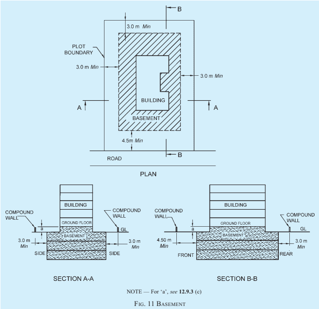
b) be constructed to a height not less than 1 m above the surrounding ground level, to form a parapet or kerb and to prevent surface water from flowing into a well, and shall be surrounded with a paving constructed of impervious material which shall extend for a distance of not less than 1.8 m in every direction from the parapet from the kerb forming the well head and the upper surface of such a paving shall be sloped away from the well;
c) be of sound and permanent construction (Pucca) throughout. Temporary or exposed (Kutcha) wells shall be permitted only in fields or gardens for purposes of irrigation; and
d) have the interior surface of the lining or walls of the well be rendered impervious for a depth of not less than 1.8 m measured from the level of the ground immediately adjoining the well-head.
12.18.1 The minimum width, minimum tread width and maximum riser of staircases for buildings shall be as given in 12.18.1.1 to 12.18.1.3 (see also Part 4 'Fire and Life Safety' of the Code).
The following minimum width shall be provided for staircases for respective occupancies (see 7.1 and Part 4 ‘Fire and Life Safety’ of the Code for classification of buildings based on occupancy):
a) Residential (A-2) : 1.00 m NOTE — For row housing with 2 storeys, the minimum width shall be 0.75 m.
b) Residential (A-1, A-3 and A-4) : 1.25 m
c) Residential hotel (A-5 and A-6) : 1.50 m
d) Assembly : 2.00 m NOTE — The width of stairs may be accepted to be 1.50 m in case of assembly occupancy having less than 150 persons
e) Educational : 1.50 m
f) Institutional : 2.00 m
g) All other occupancies : 1.50 m
The minimum width of tread without nosing shall be 300 mm. However, for one or two family dwelling, it may be reduced to not less than 250 mm.
The maximum height of riser shall be 150 mm. However, for one or two family dwelling, it may be increased to not more than 190 mm. The number of risers shall be limited to 12 per flight.
12.18.2 The minimum head-room in a passage under the landing of a staircase shall be 2.2m. The minimum clear head-room in any staircase shall be 2.2m.
All aspects of exit requirements for corridors, doors, staircases, ramps, etc, in respect of widths, travel distance shall be as per Part 4 ‘Fire and Life Safety’ of the Code.
12.19.1 The roof of a building shall be so designed and constructed as to effectively drain water by means of sufficient rain water pipes of adequate size, wherever required, so arranged, jointed and fixed as to ensure that the rain water is carried away from the building without causing dampness in any part of the walls, roof or foundations of the building or an adjacent building.
12.19.2 The Authority may require rain water pipes to be connected to a drain or sewer to a covered channel formed beneath the public footpath to connect the rain-water pipe to the road gutter or in any other approved manner.
12.19.3 Rain-water pipes shall be affixed to the outside of the external walls of the building or in recesses or chases cut or formed in such external walls or in such other manner as may be approved by the Authority.
12.19.4 It is desirable to conserve rain water using suitable rain water harvesting techniques including by
roof water collection. In this context, reference shall be made to Part 9 ‘Plumbing Services (including Solid Waste Management), Section 2 Drainage and Sanitation’ of the Code.
For all buildings above 15 m in height and in special occupancies, like educational, assembly, institutional, industrial, storage, hazardous and mixed occupancies with any of the aforesaid occupancies having area more than 500 m² on each floor, provision shall be made for an independent and ventilated meter (service) room, as per requirements of electric (service) supply undertakings on the ground floor with direct access from outside for the purpose of termination of electric supply from the licensee's service and alternative supply cables. The door/doors provided for the service room shall have fire resistance of not less than two hours.
13.1.1 These requirements deal with barrier free access to, movement within and around buildings, by the elderly persons and persons with disabilities who may have non-ambulatory disabilities, ambulatory disabilities, sight disabilities, hearing disabilities, disabilities of inco-ordination, ageing, allergies, heart and lung diseases, epilepsy, haemophilia, incontinence, enterostomy, etc.
It is intended to make all buildings and facilities used by the public accessible to, and usable by all people including those living with disabilities and may include those with inability to walk or difficulty in walking, reliance on walking/mobility aids, blindness and visual impairments, speech and hearing impairments, in-coordination of motor movements, reaching and manipulation, lack of stamina, difficulty in interpretation and reacting to sensory information and extremes in physical sizes. It supplements the general requirements of this Part of the Code, and reflects greater concern for safety of life and limb of every resident irrespective of age, gender or abilities.
13.1.2 These requirements apply to all buildings and facilities open to and used by the public. These shall also apply to all forms of public housing by the government/civic bodies or private developers. It does not apply to private residences. For extent of application of requirements covered under 13 to different building occupancy types, reference shall be made to 13.5.
13.1.3 The reference to the accessibility needs of persons with disabilities, made in this Part shall also mean a reference to such needs of the elderly persons, children and persons of too short stature in so far as the concerned provision is applicable to the type of disabilities that may be associated therewith.
13.2 For the purpose of this clause, the following definitions shall apply.
13.2.1 Ability — identifiable human attribute, including but not exclusively, to walk, to speak, to hear, to see, to feel by touch, to taste, to understand, and to recognize.
13.2.2 Access Aisle — An accessible pedestrian space between elements, such as parking spaces, seating and desks, that provides clearances appropriate for use of the elements
Where a septic tank is used for sewage disposal, the location, design and construction of the septic tank shall conform to requirements of 12.15.1 and 12.15.2 [see also Part 9 ‘Plumbing Services (including Solid Waste Management), Section 2 Drainage and Sanitation’ of the Code].
A subsoil dispersion system shall not be closer than 18 m from any source of drinking water, such as well, to mitigate the possibility of bacterial pollution of water supply. It shall also be as far removed from the nearest habitable building as economically feasible but not closer than 6 m, to avoid damage to the structures.
a) Dimensions of septic tanks — Septic tanks shall have a minimum width of 750 mm, a minimum depth of 1 m below the water level and a minimum liquid capacity of 1 m³. The length of tanks shall be 2 to 4 times the width;
b) Septic tanks may be constructed of brickwork, stone masonry, concrete or other suitable materials as approved by the Authority;
c) Under no circumstances shall effluent from a septic tank be allowed into an open channel drain or body of water without adequate treatment;
d) The minimum nominal diameter of the pipe shall be 100 mm. Further, at junctions of pipes in manholes, direction of flow from a branch connection shall not make an angle exceeding 45° with the direction of flow in the main pipe;
e) The gradients of land drains, under-drainage as well as the bottom of dispersion trenches and soakways shall be between 1:300 and 1:400;
f) Every septic tank shall be provided with ventilating pipe of at least 50 mm diameter. The top of the pipe shall be provided with a suitable cage of mosquito-proof wire mesh.
The ventilating pipe shall extend to a height which would cause no smell nuisance to any building in the area. Generally, the ventilating pipe may extend to a height of about 2 m, when the septic tank is at least 15 m away from the nearest building and to a height of 2 m above the top of the building when it is located closer than 15 m;
g) When the disposal of septic tank effluent is to a seepage pit, the seepage pit may be of any suitable shape with the least cross-sectional dimension of 0.90 m and not less than 1.00 m in depth below the invert level of the inlet pipe. The pit may be lined with stone, brick or concrete blocks with dry open joints which should be backed with at least 75 mm of clean coarse aggregate. The lining above the inlet level should be finished with mortar. In the case of pits of large dimensions, the top portion may be narrowed to reduce the size of the RCC cover slabs. Where no lining is used, specially near trees, the entire pit should be filled with loose stones. A masonry ring may be constructed at the top of the pit to prevent damage by flooding of the pit by surface runoff. The inlet pipe may be taken
13.3.1 These requirements relate to the principal human
abilities that should be considered when designing, constructing and managing the built environment. Some of these abilities are described in B-1 which gives an overview of concerned design considerations that should be taken into account.
Understanding of the human abilities or limitation thereof as described below, and design aspects according to the same, when fully implemented, are expected to benefit all people:
a) Non-ambulatory disabilities — Impairments that, regardless of cause or manifestation, for all practical purposes, make an individual a wheelchair user for his mobility. The requirement of non-ambulatory disabilities relates primarily to the design of buildings, so as to meet their independent mobility needs while sitting in the wheelchair with or without assistance, minimum widths and heights, level changes and signage, etc.
b) Ambulatory disabilities — Impairments that cause individuals to walk with difficulty or insecurity of balance. Such persons are able to walk on level, either with or without personal assistance, and may depend on prostheses (artificial limbs), orthoses (calipers), sticks, crutches or walking aids or may negotiate suitably graded steps provided that convenient handrails are available. For example elders using walking sticks, ladies in advance stage of pregnancy, temporary disabilities, such as, fracture, individuals using braces or crutches, amputees, persons having arthritis, those with spasticity and those with pulmonary and cardiac ills, etc, may be ambulatory disabled.
c) Sight disabilities — Total blindness or impairments affecting sight to the extent that the individual may have to use his other sensory organs such as sense of touch and hearing, use assistive devices for orientation in the environment, such as white cane. Accordingly, building design needs to take in to account means, such as, tactile, Braille and audio-visual, and colour contrasting signage.
d) Hearing disabilities — Deafness or hearing impairment may affect an individual's verbal communication or ability to hear warning signals in the environment. The buildings needs to be designed to provide more visual signage, induction loops for hearing enhancement, emergency audio-visual sirens, etc.
e) Disabilities of incoordination — Incoordination of motor movements due to cerebral palsy, spinal injury or peripheral nerve injury.
Special requirements of low income housing shall be as given in Annex C. For detailed information in this regard, reference may be made to the accepted standard [3(3)].
With the exception of requirements given in Annex C, requirements of building shall be governed by the provision of this Code.
For requirements regarding structural design, reference shall be made to Part 6 ‘Structural Design’ of the Code. For requirements regarding construction (including management and safety), reference shall be made to Part 7 ‘Construction Management, Practices and Safety’ of the Code.
20.1 For requirements regarding lighting and ventilation for different uses and occupancies, reference shall be made to Part 8 ‘Building Services’, Section 1 ‘Lighting and Natural Ventilation’ of the Code.
Rooms shall have, for the admission of light and air, one or more openings, such as windows and ventilators, opening directly to the external air or into an open Verandah.
20.1.2 Notwithstanding the area of openings obtained through 20.1, the minimum aggregate area (see Notes 1 to 3) of such openings, excluding doors inclusive of frames, shall be not less than,
a) one-tenth of the floor area for hot-dry climate;
b) one-sixth of the floor area for warm-humid climate;
c) one-eighth of the floor area for temperate and composite climate; and
d) one-twelfth of the floor area for cold climate.
1 If a window is partly fixed, the openable area shall be counted. 2 No portion of a room shall be assumed to be lighted, if it is more than 7.5 m away from the opening assumed for lighting that portion.
3 The area of openings as given in (a) to (d) above shall be increased by 25 percent in the case of a kitchen [see 12.3.3(d)].
For requirements regarding design, construction and installation of air conditioning, heating and mechanical ventilation systems, reference shall be made to Part 8 ‘Building Services, Section 3 Air Conditioning, Heating and Mechanical Ventilation’ of the Code.
21.1 For requirements regarding electrical installations in buildings including lightning protection of buildings, reference shall be made to Part 8 'Building Services
Section 2 Electrical and Allied Installations' of the Code.
The solar panels can be provided on roof tops and integrated photovoltaic panels on walls/windows as well as solar photovoltaic (PV) banks on open areas.
All plots having size 500 m² and above shall install solar photovoltaic power generation system. This should also be encouraged for plots smaller than 500 m² . The power generated may be used for in-house utilization or for transfer to the grid. The Authority shall have required provisions in the building bye-laws and mechanism for required clearances and approvals. The Authority shall also specify minimum generation requirement. The following may be used as a guide:
| Sl No.(1) | Building Type(2) | Plot Size(3) | Generation Requirement(4) |
|---|---|---|---|
| i) | Residential (Plotted houses) | 100 m² and above | 1 kWp or 5 percent of connected load, whichever is higher |
| ii) | Residential (Group housing) | All sizes | Minimum 5 percent of connected load |
| iii) | Business, educational buildings having connected load of 30 kW and above | 500 m² and above | 5 kWp or 5 percent of connected load, whichever is higher |
| iv) | Mercantile, hotels, motels, assembly, industrial and institutional buildings | 500 m² and above | for buildings having connected load of:a) 50-1 000 kW — 10 kWp or 5 percent of connected load whichever is higherb) Above 1 000 kW — 50 kWp or 5 percent of connected load whichever is higher |
Provision for lifts shall be made for buildings 15 m or more in height. For requirements regarding planning, designing and installation, etc, of lifts and escalators, reference shall be made to Part 8 ‘Building Services, Section 5 Installation of Lifts, Escalators and Moving Walks’ of the Code.
Table 9 Norms for Off-Street Parking Spaces (Clause A-1)
A-1 The off-street parking spaces shall be as given in Table 9.
| Sl No. | Occupancy | One Car Parking Space for Every | ||||
| Population Less than 50 000 | Population Between 50 000 and 200 000 | Population Between 200 000 and 1 000 000 | Population Between 1 000 000 and 5 000 000 | Population Above 5 000 000 | ||
| (1) | (2) | (3) | (4) | (5) | (6) | (7) |
| i) | Residentiala) Multi-family | — | — | a) 2 tenements having built-up area 101 to 200 m2 | 1 tenement of 100 m2 built-up area | a) 1 tenement of 75 m2 built-up area |
| b) 1 tenement of built-up area above 200 m2 | b) 1/2 tenement of built-up area above75 m2 | |||||
| b) Lodging establishments, tourist homes and hotels, with lodging accommodation | 12 guest rooms | 8 guest rooms | 4 guest rooms | 3 guest rooms | 2 guest rooms | |
| ii) | Educational (see Note 1) | — | — | 70 m2 area or fraction thereof of the administrative office area and public service areas | 50 m2 area or fraction thereof of the administrative office area and public service areas | 35 m2 area or fraction thereof of the administrative office area and public service areas |
| iii) | Institutional (Medical) | 20 beds (Private) 30 beds (Public) | 15 beds (Private) 25 beds (Public) | 10 beds (Private) 15 beds (Public) | 5 beds (Private) 10 beds (Public) | 2 beds (Private) 5 beds (Public) |
| iv) | a) Assembly halls, cinema theatres | 120 seats | 80 seats | 25 seats | 15 seats | 10 seats |
| b) Restaurants | 60 seats | |||||
Special Requirements for Low Income Housing in Urban Areas
These guidelines cover the planning and general building requirements of low income housing in urban areas, for houses having a maximum plinth area of 40 m² including future expansion. The requirement regarding layout planning of low income housing colonies are applicable to public and private agencies/government bodies. The requirements on design and construction of buildings for low income housing in approved layouts are applicable to all private and public agencies.
C-2 Planning
The type of development for low income housing shall be plotted developments as row housing/flatted development as row housing or group housing on cluster pattern (see Annex D).
C-2.2.1 In the land to be developed, at least 75 percent of the plots may be of the size less than or up to 60m²
per dwelling unit in metropolitan towns and 100 m² in other towns and hill areas. Remaining 25 percent of the plots may be more than 60 m² , however, no plot shall be more than 200 m² . In case of group housing or flatted development at least 75 percent units should have a plinth area (excluding external circulation such as stairs, lifts, lobbies, etc) up to or not exceeding 40 m² including future expansion.
C-2.2.2 The mix of plot of different sizes should have a wide range to accommodate the need of lower income group. The project may include more than one site provided they are in the same neighbourhood.
C-2.2.3 The layout should generally conform to the following land use:
| Sl No. | Land Use | Percentage of Land Under Each Use | |
| General (3) | Hill Area (4) | ||
| (1) | (2) | ||
| i) | Saleable: | ||
| a) Residential | 50, Min | 35 | |
| b) Work places, schools institutions, shops, community places, etc | 20, Max | 15 | |
| ii) | Non-saleable: | ||
These guidelines cover planning and building requirements of housing developed as clusters. These requirements are applicable to all housing projects taken up by public, private or cooperative agencies.
D-2 Planning
The minimum plot size permissible shall be 15 m² with 100 percent ground coverage and an FAR of 2. 100 percent ground coverage and FAR of 2 will be applicable up to plot size of 25 m² . For plot sizes beyond 25 m² , provision in accordance with good practice [3(3)] shall be applicable.
In case of slum resettlement on the same site, minimum area may be reduced to 12.5m² with potential for adding another 12.5m² on first floor with an internal staircase.
Group housing may be permitted within cluster housing concept. However, dwelling units with plinth areas up to 20 m² should have scope for adding a habitable room. Group housing in a cluster should not be more than 15 m in height.
In ground and one storeyed structures not more than 20 houses should be grouped in a cluster. Clusters with more dwelling units may create problems relating to identity, encroachment and maintenance.
Minimum dimensions of open spaces shall be not less than 6 m or 3/4th of the height of buildings along the cluster open space, whichever is higher. The area of such cluster court shall not be less than 36 m². Group housing around a cluster open space should not be normally more than 15 m in height. Maximum cluster courtyard width and breadth shall be 13 m.
No setbacks are needed from the edges of cluster as pedestrian/vehicular access roads surrounding the cluster.
NATIONAL BUILDING CODE OF INDIA 2016
Pedestrian paths and vehicular access roads to clusters separating two adjacent clusters may be bridged to provide additional dwelling units. While bridging the pedestrian path way minimum clearance should be one storey height, length of such bridging should be not more than two dwelling units. While bridging the vehicular access roads minimum clearance should be 6 m.
Adequate space should be allocated for persons using mobility devices, for example wheelchairs, crutches and walkers, white cane etc, as well as those walking with the assistance of others. The dimensions prescribed in B-1.1 to B-1.4 may be used for guidance while designing facilities and equipment to be used by persons with disabilities.
B-1.1 Mobility Devices and Space Allowance
The basic elements of wheelchairs (manual, electric and any others) and terms and definitions for these elements are as defined in the accepted standard [3(6)]. Basic elements of a wheelchair (folding, adult size) are also shown in Fig. 12.
Wheelchair requirements are given in the accepted standards [3(7)].
B-1.1.1.1 Some of the dimensions of a standard wheelchair are extremely important and helps to arrive at requirements for space allowance, reach range, etc, of a wheelchair user. Electric wheelchair may be of a large dimension, much heavier and do not have the same manoeuvrability/capability as manual wheelchairs.
B-1.1.1.2 Manual wheelchair dimensions are as follows (see Fig. 12):
a) Overall length : 1 000 mm -1 100 mm
b) Overall width, open : 650 mm - 720 mm
c) Overall width, : 300 mm - 330 mm folded
d) Overall height : 910 mm - 950 mm
e) Seat height from : 480 mm - 510 mm floor at the front
f) Distance between : 400 mm - 450 mm seat and footrest
g) Arm rest height : 220 mm - 230 mm from seat
m) Seat depth : 420 mm - 440 mm
n) Clearance of foot- : 90 mm - 200 mm rest from floor
p) Clearance of frame : 90 mm, Min from floor
q) Wheelchair footrest : 350 mm (deep)
r) Wheelchair castor : 12 mm width
s) Weight of the : 25 kg, Max wheelchair (basic model)
The following form important considerations in deciding various space requirements to ensure functionality for wheelchair users:
13.2.3 Accessible Site, Building, Facility or Portions — A site, building, facility, or portions thereof that complies with the requirements given in this clause to
which people, regardless of their disability, age or gender are able to gain access to, in to them, to use them and exit from them with dignity.
NOTE — Accessibility includes ease of independent approach, entry, evacuation and/or use of a building and its services and facilities, by all of the building's potential users with an assurance of individual health, safety and welfare during the course of those activities.
13.2.4 Accessible Route — A continuous unobstructed path connecting all accessible elements and spaces in a building or facility that may be negotiated by a person with disability using a wheelchair and that is also safe for and usable by persons with other disabilities. Interior accessible routes may include corridors, ramps, elevators, lifts, and clear floor space at fixtures. Exterior accessible routes may include parking, access aisles, kerb ramps, walkways, pathways, footpaths/sidewalks, and ramps.
13.2.5 Accessible Toilet — A compartment having the basic requirements of minimum clear spaces, water-closet, washbasin and other essential washroom accessories as required by people with non-ambulatory disabilities. There are also toilets for ambulant disabled which provide accessibility for convenient use by persons with ambulatory disabilities.
13.2.6 Ageing — Those manifestations of the ageing processes that significantly reduce mobility, flexibility, coordination, and perceptiveness but are not accounted for in disability categories mentioned elsewhere in this Part.
13.2.7 Area of Rescue Assistance — Building space directly adjoining, and visible from, a main vertical evacuation route, robustly and reliably protected from heat, smoke and flame during and after a fire, where people can temporarily wait with confidence for further information, instructions, and/or rescue assistance, without obstructing or interfering with the evacuation travel of other building users
NOTE — ‘Robust’ means structurally hardened and resistant to mechanical damage during the fire and for a period of time afterwards, that is, the cooling phase.
13.2.8 Assistive Product/Device — Product/device especially produced or generally available, for preventing, compensating for, monitoring, relieving or neutralizing impairments, activity limitations and participation restrictions.
13.2.9 Assisted Evacuation — Strategy that exists during which a designated person or persons provide assistance, during an emergency, to another person to leave a building or a specific part of the built environment and to reach a final place of safety.
13.2.10 Automatic Door — A door equipped with a power operated mechanism and controls that open and close the door automatically upon receipt of a
momentary signal. The switch that begins the automatic cycle may be photoelectrical device, floor mat, sensing device, or manual switch mounted on or near the door itself.
13.2.11 Circulation Path — An exterior or interior way of passage from one place to another for pedestrians, including walkways, pathways, hallways, courtyards, stairways and stair landings.
13.2.12 Circulation Space — Unobstructed space necessary for access to, into and within and egress from any part of the built environment.
13.2.13 Clear — Unobstructed.
13.2.14 Colour Contrast — The difference in colour that makes an object (or its representation in an image or display) distinguishable. It is determined by the difference in the colour of the object and other objects within the same field of view. Distinguishing one form/object from another by hue is the most basic and easily understood contrast.
NOTE — The basic guidelines for making effective colour choices are based on the hue value of the colours. The most commonly used methods of achieving colour contrast incorporate either harmonizing or contrasting colour combinations. Contrast of hue is what relates most directly to the colour wheel combinations. The further away from each other two colours are, the higher the contrast. This means that the complementary colour combination has the highest contrast, while the analogous combination has the lowest.
13.2.15 Disability — An umbrella term for impairments, activity limitations, and participation restrictions, denoting the negative aspects of the interaction between an individual (with a health condition) and that individual's contextual factors(environmental and personal factors). Disability is neither simply a biological nor a social phenomenon but arises from the relationship between health condition and context.
13.2.16 Grab Bars — A bar used to give a steadying or stabilizing assistance to a person engaged in a particular function.
13.2.17 Handrails — A rail used in circulation areas such as corridors, passageways, ramps and stairways to assist in continuous movement.
13.2.18 Hue — Attribute of visual sensation which has given rise to colour names, such as, blue, green, yellow, red and purple.
NOTE — People with normal colour vision report that hues follow a natural sequence based on their similarity to one another. With most colour deficits, the ability to discriminate between colours on the basis of hue is diminished.
13.2.19 Impairment — Limitation in body function or structure such as a significant deviation or loss which can be temporary due, for example to injury, or permanent, slight or severe and can fluctuate over time, in particular, deterioration due to ageing.
NOTE — Body function can be a physiological or psychological function of a body system; body structure refers to an anatomic part of the body such as organs, limbs and their components.
13.2.20 International Symbol of Accessibility — The symbol consisting of a square overlaid with a stylized image of a person using a wheelchair (see B-24.2.16 and Fig. 105).
NOTE — The symbol is often provided where access has been improved, particularly for wheelchair users and other mobility impaired persons. The symbol denotes a barrier free environment, to help older people, parents with prams and travellers with luggage besides persons with disabilities. The wheelchair symbol is always facing to the right.
13.2.21 Kerb — A side barrier to a trafficable surface or the edge where a raised sidewalk/footpath, road median, or road shoulder meets an unraised street or other roadway.
13.2.22 Kerb Ramp — A short ramp cutting through a kerb or built up to it.
13.2.23 Knurled Surface — Roughened area, often in a crisscross pattern; used on grab bars to improve grasp and to prevent slipping.
13.2.24 Landing — A platform or part of a floor structure at the end of a flight of stairs or a ramp or at the entrance to a lift car.
13.2.25 Light Reflectance Value (LRV) — The total quantity of visible light reflected by a surface at all wavelengths and directions when illuminated by a light source.
13.2.26 Manoeuvring Zone — The minimum three dimensional space within which it is feasible to complete a manoeuvre needed to gain access to a specific facility, component or fitting, in particular while using a wheelchair or a walking aid.
13.2.27 Ramp — The construction, in the form of an inclined plane that is steeper than or equal to 1:20 (5 percent) from the horizontal, together with any intermediate landing, that makes it possible to pass from one level to another (see B-6.2).
13.2.28 Operable Parts — A part of a piece of equipment or appliance used to insert or withdraw objects, or to activate, deactivate, or adjust the equipment or appliance (for example coin slot, push button, handle, etc).
13.2.29 Persons with Disabilities — A person with any physical, mental, intellectual or sensory impairment which in interaction with various barriers may hinder full and effective participation in society on an equal basis with others.
13.2.30 Space — A definable area (for example toilet room, hall, assembly area, entrance, storage, room alcove, courtyard, or lobby).
13.2.31 Tactile — That relating to perception using the sense of touch.
NOTE — It relates to information and interpretations derived from the sense of touch. This involves sensory transfer through physical contact of the hands or feet with other surfaces, as well as sensory transfers received by contact with non-physical elements such as pressure, wind and temperature.
13.2.32 Tactile Ground Surface Indicators — Indicators profiled paving surface with visual contrast criteria to enable a person with impaired sight using a long cane, underfoot or visual identification to detect a specific route (guiding pattern) or the presence of a hazard (attention pattern). These are also called tactile tiles or tactile walking surface indicators.
NOTE — These indicators which provide a distinctive surface pattern of strips and truncated domes or cones (small domes or cones that have had their tops cut off, or truncated) are used to guide/alert persons with vision impairments of their approach to facilities, streets and hazardous drop-offs. People who are blind or visually impaired are alerted of impending danger from vehicle impact or a grade change.
13.2.33 Tactile Guiding Blocks — Tiles of size 300 mm × 300 mm that incorporate flat topped bars 5 mm ( ± 0.5 mm ) high, 20 mm wide and spaced 50 mm from the centre of one bar to the centre of the next, and are easily detectable underfoot by persons with visual impairments. They are used externally to guide people with visual impairments along the circulation path. They may also be used internally in large busy areas such as railway stations and airports.
13.2.34 Tactile Warning Blocks — Tiles of size 300 mm × 300 mm that incorporate rows of 5 mm ( ± 0.5 mm ) high flat topped blister like domes that are easily detectable underfoot by persons with visual impairments, recognized as a sign of approaching hazards. These are placed along the approach path to unavoidable obstacles and hazards to warn persons with visual impairments of the approaching danger or level change.
13.2.35 Tactile Signs — Tactile signage incorporates raised text or symbols to enable touch reading by people who are blind, and touch enhancement of visual perception for people who are vision impaired.
13.2.36 Unobstructed Width — Free unobstructed space necessary for passage through a doorway, along a passageway, or other route element (for example stairway).
13.2.37 Unobstructed Width, Door — Available width for passage through a door opening, clear of all obstructions, measured when the door is opened 90° , or when a sliding or folding door is opened to its fullest extent
13.2.38 Unisex Accessible Toilet — Accessible toilets that can be used by both sexes.
NOTE — Unisex accessible toilets allow the greatest flexibility for people who require assistance.
13.2.39 Universal Design — The design of products and environments to be usable by all people, to the greatest extent possible, without the need for adaptation or specialized design.
13.2.40 Visual Contrast — Visual perception between one element of a building and another. This can be produced by a difference in light reflectance value (LRV) or luminance, also called luminance contrast.
NOTE — Light reflectance value is measured on a scale of 0 to 100 where 0 equals black meaning total light absorption and 100 equals white meaning total light reflection.
A simple formula for visual contrast is given below for guidance:
Visual contrast = [ (B 1 - B 2) / B 1 ] × 1 0 0, in percent
where
B 1 = LRV of the lighter area; and
B2 = LRV of the darker area.
In most circumstances, a difference in these values of 30 percent is considered adequate. However, research suggests that signs are more legible for the visually impaired when characters contrast with their background by at least 70 percent.
13.2.41 Walks (Walkways) — A predetermined prepared surface, exterior pathway leading to or from a building or facility, or from one exterior area to another, placed on the existing ground level and not deviating from the level of the existing ground immediately adjacent.
13.2.42 Way Finding — Descriptive of a system whereby appropriate information is provided to assist a person to pass through the built environment towards a specific destination.
NOTE — Way finding includes orienting oneself, knowing one's destination, following the best route, recognizing one's destination and finding one's way back out. People who are blind or who have a vision impairment benefit from tactile information to facilitate way finding.
13.2.44 Water-Closet Compartment/Toilet Cubicle — A compartment having a water-closet with grab bars installed to assist persons with physical disabilities/mobility impairments.
13.2.45 White Cane — A long rod-like device used by blind or visually impaired travellers to give them information about the environment they are travelling through.
down a depth of 0.90 m from the top as an anti-mosquito measure; and
h) When the disposal of the septic tank effluent is to a dispersion trench, the dispersion trench shall be 0.50 m to 1.00 m deep and 0.30 m to 1.00 m wide excavated to a slight gradient and shall be provided with 150 mm to 250 mm of washed gravel or crushed stones. Open jointed pipes placed inside the trench shall be made of unglazed earthenware clay or concrete and shall have a minimum internal diameter of 75 mm to 100 mm. Each dispersion trench shall not be longer than 30 m and trenches shall not be placed closer than 1.8 m.
In the case of multi-storeyed multifamily dwelling apartments constructed by existing and proposed Cooperative Housing Societies or Apartment Owners Associations, limited companies and proposed societies, an office-cum-letter box room of dimension 3.6 m × 3 m shall be provided on the ground floor. In case the number of flats is more than 20, the maximum size of the office-cum-letter box room shall be 20 m² .
Provision shall be made for letter boxes on the entrance floor as per the requirements of the postal department.
f) People with allergies — People with allergies may be sensitive to dust, mildew, pollen, animal hair, formalin, turpentine, etc. Some are sensitive to contact with substances and materials such as nickel, chromium and rubber.
g) People with heart and lung diseases — People with heart and lung diseases may only be able to walk short distances and may be unable to climb stairs. The requirements of these people are similar to those with impaired mobility.
h) People with epilepsy, haemophilia, etc — The requirements of those with epilepsy, heamophilia, etc, are related primarily to the design of buildings and the need to minimize the risk of injury caused by falling or encountering obstacles.
j) People with incontinence, enterostomy operations, etc — The requirements of people with incontinence, enterostomy operations, etc, (colostomies, ileostomies and urostomies) are mainly related to bathroom provision. In certain circumstances, for example in public water-closet compartments, it may be desirable to provide a special sink for emptying urine bags.
k) People with hidden (such as strength, stamina, dexterity and allergy) impairments, and
m) People with diversities in age and stature (including frail persons).
Entering, using and evacuating buildings should be safe and easy for individuals, families and groups which include persons with disabilities. The main considerations are as follows:
Pedestrian access into site;
Designated vehicular parking near the main entrance;
Accessible path to the entrance;
Appropriate external lighting;
Accessible external furniture (seats, bins, etc);
Accessible information at the entrance to the site;
Suitable drop-off point near main entrance;
Reduced travelling distances;
Level entrances and exits;
Simple and logical layouts;
Unobstructed level circulation;
Easy access to information desks, lifts and toilet compartments for disabled persons;
Intuitive, obvious and accessible means of egress;
Spacious lifts;
Safe stairs that are easy to use, and facilitate safe assisted evacuation/rescue in emergencies;
Slip-resistant walking surfaces;
Wide door openings and easy door operation, sufficient space around doors that makes it possible to open and close them when seated in a wheelchair;
Adequate manoeuvring space;
Adequate height, location and easy operation of controls and switches;
Good lighting;
Good visual contrast of walls, floors, doors and signage;
Good signage;
Important information communicated via two senses or more (tactile, audible and visual);
Good acoustics;
Hearing enhancement systems; and
Management and maintenance of the built environment.
The key accessibility issues are highlighted in Table 7.
13.4 Various key accessibility issues shall be taken into account for ensuring accessibility in built environment in accordance with the provisions given in Annex B in regard to anthropometrics and specific requirements on site planning and development, designated accessible parking space, approach to the buildings, access at entrance and within the buildings, controls and operating mechanisms, seating spaces, other facilities, level changes, toilet and sanitary facilities, emergency evacuation in buildings, signages, etc. Requirements for accessibility in buildings and built environment as given in other Parts/Sections of the Code shall also be complied with.
13.5 Various accessibility requirements for persons with disabilities and the elderly shall be applied to different building occupancies in accordance with Table 8, unless mentioned otherwise specifically in Annex B. In addition, all building occupancy types shall comply with the following:
a) At least one entrance preferably the main entrance per building shall be accessible. All efforts should be made to make as many/all entrances accessible.
b) All common areas open to public and staff and all facilities provided in a building for
| SI No.(1) | Key Accessibility Issues(2) | Example(3) |
|---|---|---|
| i) | Equitable approach to a building, for example designated parking, clear pedestrian routes separate from vehicles and cyclists, no steps or obstacles, short distances from parking and public transport, good signage, good lighting and good contrast | |
| ii) | Equitable entry via the same entrances, for example easy to locate main entrances, no steps or obstacles, wide openings, adequate manoeuvring space in front of the door, low operating forces, good signage, good lighting and good visual contrast | |
| iii) | Equitable use of the same paths in horizontal circulation, for example no steps or obstacles, adequate manoeuvring space, wide door openings, easy to operate doors, resting places, clear layout, good signage, good lighting and good visual contrast | |
| iv) | Equitable access to the same paths in vertical circulation, for example safe stairs, spacious lifts with easy operation, good signage, good lighting and good visual contrast | |
| v) | Equitable use of the same rooms, for example ample circulation space and different seating possibilities, good acoustics and hearing enhancement systems, good lighting and good visual contrast | |
| Table 7 — (Concluded) | Table 7 — (Concluded) | Table 7 — (Concluded) |
| (1) | (2) | (3) |
| vi) Equitable use of the same equipment and facilities, for example easy to understand and operate, adequate manoeuvring space and operating height, information via two senses | vi) Equitable use of the same equipment and facilities, for example easy to understand and operate, adequate manoeuvring space and operating height, information via two senses | |
| vii) Equitable use of toilet and sanitary facilities, for example good signage, adequate manoeuvring space, good transfer options, well-placed equipment, easy operation | vii) Equitable use of toilet and sanitary facilities, for example good signage, adequate manoeuvring space, good transfer options, well-placed equipment, easy operation | |
| viii) Equitable means of egress, concepts for emergency planning, for example no steps or obstacles, fire protected lifts, good signage, good lighting, good visual contrast, good fire safety, protection and evacuation, accessible means of egress | viii) Equitable means of egress, concepts for emergency planning, for example no steps or obstacles, fire protected lifts, good signage, good lighting, good visual contrast, good fire safety, protection and evacuation, accessible means of egress |
| SI No.(1) | Category(2) | Type of Built Environment Within the Category(3) | Applicability(4) |
|---|---|---|---|
| i) | Residential | Public housing including low income housing and housing developed by private developers | a) All common and communal areas, such as, approach, entrances/exits, lifts, stairs, lobbies, clubs, religious facilities, parking, sports facilities/parks and recreation areas, etc, and associated sanitary and other facilities therein.b) 5 percent houses to be accessible meeting accessibility requirements, preferably on ground floor.c) In all other 95 percent houses, minimum universal design features, such as, minimum clear door widths of: main entrance, rooms, kitchen and that of at least one toilet and sanitary room in each house. Such toilet and sanitary room in the house shall be the one having access from the living/drawing room and their size shall comply with those given in B-9 to allow the occupants to adapt to their needs to facilitate ageing-in-place and disabled friendly environment.NOTE □ The provisions given in (c) are minimum prescriptions with the objective to progressively move towards universal design of the buildings and the built environment, to be usable by all people, to the greatest extent possible irrespective of their age, situation, abilities, gender or any other diversity. |
| ii) | Hotels/hospitality centres | Hotels, dormitories, lodging and rooming houses, such as inns, clubs, motels and guest houses | Minimum five percent of the total rooms including their toilet room, shower room, balcony, etc, shall be accessible and preferably be provided on the ground floor for ease of evacuation in case of an emergency.All other rooms shall have universal design features (without specific adaptations like handrails/grab bars, etc). This would include minimum clear door widths of 900 mm of all entrances including those of sanitary rooms and balcony areas; and minimum passage width of 1200 mm in the rooms and required turning radius.In accommodations having more than one toilet/sanitary room, one such facility shall be accessible.In case of accessible accommodations, a choice of right or left hand transfer to the toilet and shower shall be provided. |
| iii) | Educational buildings | Schools, colleges, classrooms, libraries, assembly points, halls, staff rooms, laboratories, play grounds | a) All teaching/administrative and common areas frequented by staff/students.b) In libraries all open book stacks. Few enclosed rooms in library for those with hearing and vision impairments who may need assistance while reading.c) In laboratories, equipment and facilities. |
| iv) | Hospitals/health facilities | Hospitals/clinics/diagnostic centres/pharmacy, etc | All public areas to be accessible, including OPDs, IPDs, wards, toilets, changing rooms, sample collection rooms, x-ray rooms, patient examination rooms, medical distribution rooms/centres. |
public use, such as, waiting areas, seating spaces, coffee shops, display areas, merchandising departments, service areas, ticket counters and refreshment stands shall be accessible to all persons with disabilities. These shall also include facilities like, lobby toilets, lifts, saloons, bars, restaurants, eateries, clubs, swimming pool, parking, fitness centres/gymnasiums, religious facilities, sports facilities/parks and recreation areas, etc, within an occupancy.
c) In all buildings, accessible toilet and sanitary room(s) shall be provided in accordance with B-9. Such facility shall be provided in each toilet group in a building.
The following building occupancy types shall install solar assisted water heating system for supplying hot water:
a) Residential buildings (except hostels of educational buildings and plotted houses) having plot area 4 000 m² and above;
b) Plotted houses having plot area of 250m² and above;
c) Hostels for schools, colleges and training centres for more than 100 students;
d) Institutional buildings; and
e) Assembly buildings
The Authority shall have required provisions in the building bye-laws and mechanism for required
clearances and approvals. The Authority, considering the availability of solar energy for harnessing, shall decide the minimum capacity be installed subject to a minimum of 25 litre per day hot water yield for each bathroom and kitchen.
For solar water heating system and their installation reference shall be made to accepted standards and good practice [3(4)].
| 40 seats |
| 20 seats |
| 10 seats |
| 5 seats |
| c) Marriage halls, community halls | 600 m2 plot area | 400 m2 plot area | 200 m2 plot area | 50 m2 plot area | 25 m2 plot area |
| d) Stadia and exhibition centre | 240 seats | 160 seats | 50 seats | 30 seats | 20 seats |
| e) Sport complex (without stadium), parks and multipurpose open spaces | — | — | 1 000 m2 plot area | 500 m2 plot area | 250 m2 plot area |
| v) | a) Business offices and firms for private business | 300 m2 area or fraction thereof | 200 m2 area or fraction thereof | 100 m2 area or fraction thereof | 50 m2 area or fraction thereof | 25 m2 area or fraction thereof |
| b) Public or semi-public offices | 500 m2 area or fraction thereof | 300 m2 area or fraction thereof | 200 m2 area or fraction thereof | 100 m2 area or fraction thereof | 50 m2 area or fraction thereof |
| vi) | Mercantile (see Note 2) | 300 m2 area or fraction thereof | 200 m2 area or fraction thereof | 100 m2 area or fraction thereof | 50 m2 area or fraction thereof | 25 m2 area or fraction thereof |
| vii) | Industrial | 400 m2 area or fraction thereof | 300 m2 area or fraction thereof | 200 m2 area or fraction thereof | 100 m2 area or fraction thereof | 50 m2 area or fraction thereof |
| viii) | Storage | — | — | 500 m2 floor area or part thereof | 250 m2 area or fraction thereof | 125 m2 area or fraction thereof |
| NOTES1 In the case of auditoria for educational buildings, parking space shall be provided as per Sl No. (iv).2 For plots up to 50 m2, as in the case of shops, parking spaces need not be insisted upon.3 For other institutions, transport/communication centre, parking space requirement shall be assessed based on the proposed building.4 In case of permitted mixed residential-commercial or mixed residential-industrial areas the parking requirements shall be double the number for residential use.5 The requirements specified in this table shall not be applicable for buildings meant for parking alone, including the multi-level car parking buildings which shall be as decided by the Authority.6 Designated accessible parking spaces shall be provided in accordance with B-3 for the occupancies specified in 13. |
| Roads, pedestrian paths, drains, public and semi-public open spaces | 30, Max | 50 |
| NOTES |
| 1 Any neighbourhood development should have provision for basic civic and community facilities, however, where such facilities are available in proximity the same could be considered and, in that case, the area under residential use could be increased correspondingly. |
| 2 If land required under statutory provisions of master plan/development plan is proportionately higher but serves larger city needs, readjustment of the recommended land use pattern may be considered. Such provisions should, however, be carefully reviewed by the planning authorities to keep them to the barest minimum levels. |
C-2.3 Plot Area
The minimum plot size with ground coverage not exceeding 75 percent, shall not be less than 40m² in small and medium town and not less than 30m² in metropolitan cities. Plot sizes below 30m² but not less than 15m² may be permitted in case of cluster planning, however, in such cases the ground coverage and FAR shall be 100 percent and 2, respectively (see also Annex D for special requirements for cluster planning for housing).
1 In exceptional cases in metropolitan cities with population more than 1 million the size of plots may be brought down to 25m² in cases of low income housing colonies located in congested areas as decided by the Authority. In mega cities it may be further reduced to 15m². In such cases where plot size is below 25m², only cluster planning or group housing may be adopted.
2 A minimum of 25 percent of the plot size shall be left open without adversely affecting light and ventilation for habitable spaces and toilet. It shall not be made mandatory to leave set back on any side.
C-2.4.1 The density norms for plotted development and mixed development shall be as follows:
| Sl No.(1) | Type of Development(2) | Range of Densities (Gross)(3) |
|---|---|---|
| i) | Plotted development | 65-120 plots per hectare |
| ii) | Mixed development :a) Small townsb) Citiesc) Metropolitan cities | 75-100 dwelling units per hectare100-125 dwelling units per hectare125-150 dwelling units per hectare |
C-2.4.2 In case of developments with per dwelling unit covered area of 15 m² , four storeyed walk ups without future incremental growth with maximum densities of 500 dwelling units per hectare shall be permissible. In case of four storeyed walk ups, having two roomed dwelling unit where one room is for future expansion, maximum density of 400 dwelling units per hectare shall be permissible.
The height of building shall not exceed 15m.
NOTES
1 For buildings up to the height of 15m, there is no need to provide lifts.
2 Housing for the low-income group shall preferably be up to a maximum of two storeys.
3 Buildings for housing beyond 15 m in height should be resorted to in exceptional circumstances and it should be governed by provisions laid down in this Code.
For size of open cluster and open space, set backs, vehicular access and pedestrian paths in cluster
planning, the provisions given in Annex D shall apply.
C-3 General Building Requirements
The minimum height of plinth shall be regulated on the basis of environmental and topographical condition and higher plinth height may be required in areas prone to flooding.
C-3.3 Size of Room
Every dwelling unit to be provided should have at least two habitable rooms. Even if one room house is provided initially it should be capable of adding a new second room in future. However, in case single room tenements are required to be provided where future additions are not possible, the carpet area of multipurpose single room should be at least 12.5 m² . Such one room dwelling units with 12.5 m² carpet area of habitable space is permitted only in case of on-site rehabilitation of slum dwellers. In a house of two rooms, first room shall not be less than 9.0 m² with minimum width of 2.5 m and second room shall not be less than 6.5 m² with a minimum width of 2.1 m provided the total area of both the rooms is not less than 15.5 m² . In incremental housing the bigger room shall always be the first room.
C-3.3.1.1 To facilitate incremental housing in case of flatted development or otherwise, habitable space at mezzanine level may be permitted. The minimum size of such a mezzanine floor should not be lesser than 6.5 m² and such a floor should occupy not more than 50 percent of the room area of which it is a part. Such a mezzanine floor should have appropriate openings to facilitate light and ventilation as per C-3.6. Minimum clear height below and above the mezzanine floor should be 2.4 m and 2.1 m, respectively.
As far as possible mezzanine floor should have direct ventilation from the external face of the building. Where this is not possible ventilation through main room may be allowed provided total area of openings in the main room is provided taking into consideration area of mezzanine floor.
Such mezzanine floor may be accessible through the main room by a ladder, whose minimum angle with vertical plane should be 22.5° . Height of the riser should be less than 250 mm.
a) The size of independent water-closet shall
be 0.90m² with minimum width of 0.9m;
b) The size of independent bath room shall be 1.20 m² with a minimum width of 1.0 m ; and
c) The size of combined bath room and water-closet shall be 1.80 m² with minimum width of 1.0 m .
The size of a cooking alcove serving as cooking space shall not be less than 2.4 m² with a minimum width of 1.2 m . The size of individual kitchen provided in a two-roomed house shall not be less than 3.3 m² with a minimum width of 1.5 m .
The minimum width of individual balcony, where provided, shall be 0.9 m and shall not be more than 1.2 m and it shall not project beyond the plot line and on roads or pathway.
The minimum height of rooms/spaces shall be as follows:
a) Habitable room : 2.6 m
b) Kitchen : 2.6 m
c) Bath/water-closet : 2.1 m
d) Corridor : 2.1 m
C-3.5.1 In the case of sloping roofs, the average height of roof for habitable rooms shall be 2.6 m and the minimum height at eaves shall be 2.0 m.
The openings through windows, ventilators and other openings for lighting and ventilation shall be in accordance with 20.1.2.
NOTE — The windows and other openings shall abut onto open spaces either through areas left open within the plot or the front, side and rear spaces provided in the layouts which shall be deemed to be sufficient for light and ventilation purposes. Wherever, ventilation/lighting is provided by means of Jali or grill of any material, total area of openings shall be calculated excluding solid portion of the Jali or grill.
The following criteria shall be adopted for internal individual staircase:
a) Minimum clear width:
2 storeyed — straight : 0.60 m
2 storeyed — winding : 0.75 m
3 or more storeyed — straight : 0.75 m
3 or more storeyed — winding : 0.90 m
b) Riser : 200 mm, Max
2 storeyed : 225 mm, Min (see Note)
3 storeyed or more : 250 mm, Min NOTE — This could be reduced to 200 mm as the clear tread between perpends, with possibility of open riser as well as nosing and inclined riser to have an effective tread of 225 mm.
d) Head room — The minimum clear head room shall be 2.1 m.
The circulation area on any floor including staircase, shall not exceed 8m²/ dwelling unit.
No building plan shall be approved and no building shall be deemed to have been completed and fit for human occupation unless provision is made for water seal latrine. No dry latrine shall be allowed. Water seal latrines may also be provided on the basis of community toilets or shared toilets as per the recommendation given in good practice [3(9)].
Where leaching pits are used, it should be constructed within the premises of the households as it would be economical as well as facilitate their cleaning. However, where, due to space constraint, construction of pits within the premises may not be possible, pits may be constructed in places like lanes, streets and roads.
In case the pit is located under the road, street or foot path, the inverted level of the pipe connecting the latrine pan with the pit shall be at least 1.1 m below ground level or below the bottom of the water main existing within adistance of 3 m from the pits whichever is more. Construction of such pits may be in accordance with good practice [3(10)].
The water seal latrine should be properly maintained and kept in sanitary condition by the owner or the occupier. The contents of the septic tanks, soak pits, leach pits, etc, should be periodically emptied.
The leach pits should be cleaned only after 2 years of their being put out of service after they were full.
The area under roads and path-ways in such housing projects should normally not exceed 20 percent of the total land area of the project.
Access to the dwelling units, particularly where motorized vehicles are not normally expected should be by means of paved footpaths with a right of way of 6 m and a pathway of 2 m only. The right of way should be adequate to allow for the plying of emergency vehicles and also for road side drains and plantation.
Where pedestrian pathways are not meant for motorable access to the minimum, right of way of such pedestrian pathway shall be 3 m. Where houses are accessible from one side only pathway may be 2 m wide. The maximum length of such pathways should not be more than 60 m.
C-5.1 Requirements of fire safety, structural design, building services and plumbing services shall be as specified in the Code.
C-5.2 One water tap per dwelling unit may be provided, where adequate drinking water supply is available. If supply is inadequate, public hydrants shall be provided. In the absence of piped water supply, hand pumps may be used for provision of water supply.
C-5.3 Recognizing the need for informal use of space for shopping and informal occupation like road side repairs, Pan shops, etc, it is suggested that about (1)/(4) of the total shopping area in a layout should be reserved for such informal uses to cater to the needs of low income families.
C-5.4 The infrastructural services shall be provided before the plots are handed over to individual owners.
C-6.1 The developed plot sizes shall be as per C-2.3.1. Services should be laid by the agency concerned as per the provisions of the Code. In so far as roads and pathways are concerned, they should be in line with C-4.
C-6.2 Site and services schemes should provide for the following:
a) Complete infrastructural needs for a permanent housing, on the periphery of individual plot or a group/cluster plots;
b) A service sanitary core in the plot;
c) A skeletal structure of columns and roof or a developed plinth; and
d) Permission to allow temporary construction on the plot.
While provisions in (a) and (d) are essential for site and services projects, recommendations in (b) and (c) are additional provisions depending upon affordability.
A right of way of at least 6 m width should be provided up to the entrance to the cluster to facilitate emergency vehicle movement up to cluster.
Built area of dwelling unit within cluster shall have no setbacks from the path or road, space. Hence, the height of the building along the pathway or roads shall be not less than 60 percent of the height of the adjacent building subject to minimum of 3 m in case of pathway and 6 m in case of vehicular access.
Cluster planning methodologies result in higher densities with low rise structures. With per dwelling unit covered area of 15 m² densities of 500 dwelling units per hectare (net) shall be permissible. Densities higher than this should not be allowed.
Cluster housing for economically weaker section families may have group toilets at the rate of one water-closet, one bath and a washing place for three families. These shall not be community toilets, as keys to these toilets shall be only with these three families, making them solely responsible for the maintenance and upkeep of these toilets.
D-3 Other Requirements
With the exception of clauses mentioned above, requirements of building will be governed by the provision of this Code and good practice [3(3)].
D-3.2 Requirements of fire safety, structural design, building services and plumbing services shall be as specified in this Code.
Arm rest height from floor : 760 mm
Lap height : 675 mm
NOTE — The dimensions given above are from the point of view of better understanding and appreciation of various needs emanating therefrom. However, considering various aspects including diversity of population, stature, age, gender, etc, the
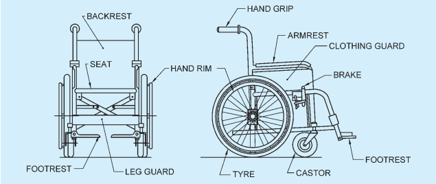
FIG. 12 NOMENCLATURE OF BASIC ELEMENTS OF WHEELCHAIR
dimensions and ranges thereof as may be applicable have been prescribed in these provisions given hereinafter.
B-1.1.1.3 A wheelchair has a footplate and leg rest attached in front of the seat. The footplate extends about 350 mm in front of the knee. The footplate may prevent wheelchair users from getting close enough to an object/site. Hence, at least 350 mm deep and 700 mm high space under a counter, stand, etc, shall be provided (see Fig. 13).
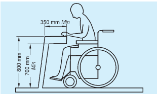
FIG. 13 NECESSARY SPACE UNDER COUNTER OR STAND FOR EASE OF WHEELCHAIR USERS
B-1.1.1.4 Clear floor space for wheelchair user
The minimum clear floor or ground area required for accommodating a single, stationary wheel chair and occupant is 900 mm × 1 200 mm (see Fig. 14). Where transfer from the wheelchair is involved, the clear space should preferably be 900 mm × 1 350 mm .
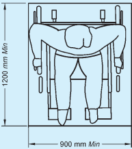
FIG. 14 CLEAR FLOOR SPACE
The minimum clear floor ground area for a wheelchair to turn is 1500mm, whereas comfortable is 1800mm and it is ideal to provide 2000mm (see Fig. 15).
Although people who use walking aids can manoeuvre through door openings of 900 mm clear width, they
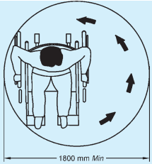
FIG. 15 PREFERRED COMFORTABLE TURNING RADIUS
need wider passageways for comfortable gaits as shown in Fig. 16. Crutch tips, often extend down out at a wide angle, and are hazardous in narrow passageways where they might not be seen by other pedestrians.
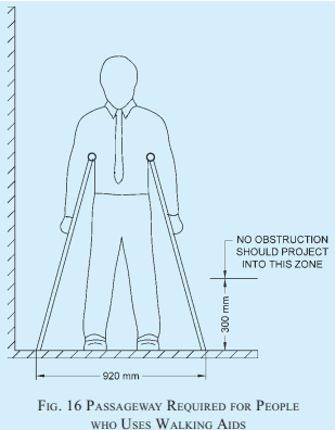
B-1.1.3 Space Allowance for White Cane Users Following shall be ensured for white cane users:
a) Protruding objects, such as directional signs, tree branches, wires, guy ropes, public telephone booths, benches and ornamental fixtures shall be installed with consideration of the range of the white cane of a person with vision impairment.
b) A barrier to warn blind or visually impaired person shall be provided under stairways or escalators so that they don't accidentally enter
in to them.
c) Walkways, halls, corridors, passage ways, aisles, or other circulations spaces shall have clear headroom to minimize the risk of accidents.
d) Adequate space allowance should be made considering that the radial range of white cane is a band of 900 mm wide (see Fig. 17).
e) Any obstacle above 300 mm cannot be detected by the white cane. If there are projections above this height then the same has to be treated in accordance with B-2.6.2.
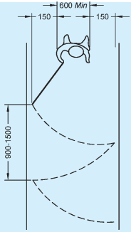
A wheelchair user's movement pivots around its shoulders (see Fig. 18). The range of reach (forward and side; with or without obstruction) of a wheelchair users, as given in B-1.2.1 to B-1.2.3 shall be taken in to consideration.
The maximum forward reach without obstruction is 1200mm from the floor and the minimum forward reach without obstruction is 400mm from the floor as shown in Fig. 19.
The maximum forward reach over an obstruction is 1000mm from the floor as shown in Fig. 20, which also indicates the touch reach and grasp reach.
The maximum side reach without obstruction is 1300mm from the floor and the minimum side reach is 250mm as shown in Fig. 21.
The maximum side reach over an obstruction of size 860 mm high × 500 mm deep is 1 200 mm from the floor as shown in Fig. 22, which also indicates the touch reach and grasp reach.
As part of the common reach zone, the comfortable reach zone when seated on a wheelchair is between 900 mm and 1 200 mm and the maximum reach zone is between 1 200 mm and 1 400 mm (see Fig. 23).
All dimensions in millimetres.
FIG. 17 SPACE ALLOWANCE (RADIAL RANGE) FOR PEOPLE USING WHITE CANES
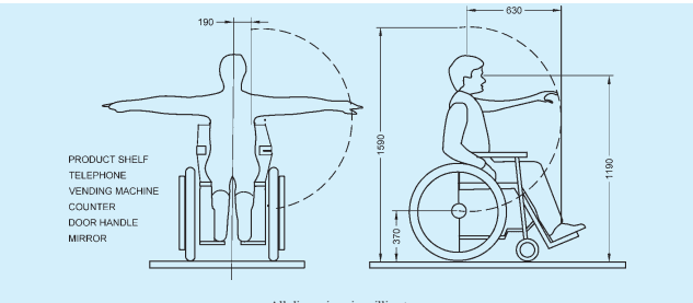
All dimensions in millimetres.
FIG. 18 RANGE OF REACH OF WHEELCHAIR USER
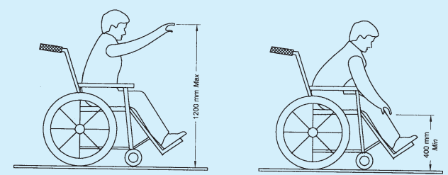
FIG. 19 FORWARD REACH WITHOUT OBSTRUCTION
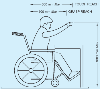
FIG. 20 FORWARD REACH OVER OBSTRUCTION
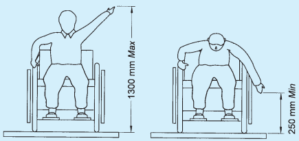
FIG. 21 SIDE REACH WITHOUT OBSTRUCTION
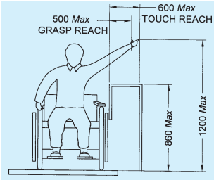
All dimensions in millimetres.
FIG. 22 SIDE REACH OVER OBSTRUCTION
Different fields of vision are given in Fig. 24. All signage should be designed based on these dimensions.
Map and information panels along pathways shall be placed at a height between 900 mm and 1 800 mm (see Fig. 25). The smallest letter shall not be less than 15 mm.
B-1.4 Heights and Widths
The average height of a person seated on a wheelchair is generally less than 1 200 mm.
The average height of a standing person is generally less than 2 000 mm.
a) Height of controls : 400 mm - 1 200 mm from floor level
b) Height for switches : 400 mm - 500 mm (power)
c) Height for switches : 800 mm - 1 200 mm (lights)
d) Height of door : 800 mm - 1 100 mm handles
e) Opening controls for : 800 mm - 1 100 mm windows
f) Space required under : 350 mm deep the counter for wheelchair footrest
a) Minimum width of entrance/ : 900 mm exit door (see Fig. 43)
b) Minimum front approach : 600 mm doorways space (see Fig. 44 and Fig. 45)
c) Minimum latch side approach : 1 250 mm doorways space (see Fig. 44)
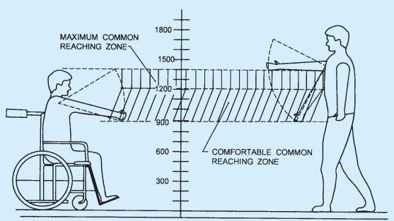
All dimensions in millimetres.
FIG. 23 COMMON REACHING ZONE
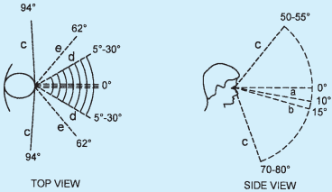
Key
a Normal optical axis, standing person
b Normal optical axis, sitting person
c Limit of field of vision
d Normal angle of vision
e Maximum angle of vision
FIG. 24 FIELD OF VISION
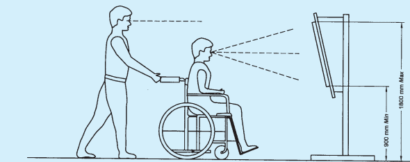
FIG. 25 VISION ZONE
B-2 Site Planning and Development
Site development is the most effective means to resolve the problems created by topography, definitive architectural designs or concepts, water table, existing streets, and typical problems, singularly or collectively, so that ingress and egress to buildings by persons with disabilities can be facilitated while preserving the desired design and effect of the architecture. Each building and its site shall be planned and designed as an integral unit from the very beginning of the design process. Equipment and materials causing allergic reactions shall as far as possible be avoided in dwellings and buildings.
The provisions of accessibility in outdoor built
environment covered herein pertain to the immediate outdoor environment of a building or of a building complex. However, these may be considered by the Authorities and concerned parties for suitably applying the same at township/city level.
B-2.2 Walkways and Pathways
Walkways and pathways (used here interchangeably) shall meet the following general requirements:
a) Walkways shall be smooth, hard and have levelled surface suitable for walking and wheeling. Irregular surfaces as cobble stones, coarsely exposed aggregate concrete, bricks, etc, often cause bumpy rides and shall be avoided.
b) Minimum walkway width shall be provided as per B-2.2.2. The width of footpath shall be in accordance with 4.3.2.1.1.
c) The walkway shall not have a gradient exceeding 1:20. If the slope or any part of a walkway on an accessible route to a building exceeds 1:20, it shall be designed and constructed as a ramp in accordance with B-6.2.
d) Where pathway meets the road, a kerb shall be provided; which shall be designed in accordance with B-2.3.
e) The cross-fall gradient across an accessible route shall not exceed 1:50 (20 mm/m), except when associated with a dropped kerb.
f) The requirements for drainage of pathways shall be as per B-2.2.5.
g) When walkways exceed 60 m in length, it is desirable to provide rest area adjacent to the walk at convenient intervals of 30 m in the form of benches/resting seats. For comfort, seat height shall be between 450 mm and 500 mm, and the seating shall have a back rest and arm rests at 700 mm height. One side of seating may be without arm rest to address the transfer needs of persons with disabilities. A colour contrast should be provided around the seating area for ease of identification by persons with low vision.
h) Texture change in walkways adjacent to seating shall be provided for persons with vision impairment by means of warning blocks (see B-2.5).
j) Gratings and manholes should be avoided in walks.
k) Walks or driveways shall have a non-slip surface. Care shall be taken to ensure that adjacent surface materials do not display different slip resistance characteristics, particularly at the edges of changes of level or gradients.
m) Such walks shall be of a continuing common surface not interrupted by steps or abrupt changes in level.
n) Wherever walks cross other walks, driveways, or parking lots, they shall blend to a common level.
p) Obstacles, such as objects or signs mounted on walls, columns or free-standing supports along the walking path shall be avoided. These shall however be regulated in accordance with B-2.6.1. Bollards along or on the walking pathway shall also be regulated in accordance with B-2.6.1. Any protruding object projecting
into a walkway shall be treated in accordance with B-2.6.2.
B-2.2.2.1 The unobstructed width of the pathway shall be,
a) not less than 1 800 mm for two-way traffic (see key 1 of Fig. 26); which may be reduced to a minimum of 1 500 mm, provided that a passing and turning space of at least 1 800 mm × 2 000 mm should be provided for every 25 m (see keys 2 and 5 of Fig. 26); and
b) not less than 1 200 mm for one-way traffic (see key 3 of Fig. 26); which may be reduced to a minimum of 1 000 mm, provided that a passing and turning space of at least 1 800 mm × 2 000 mm should be provided for every 25 m (see keys 4 and 5 of Fig. 26).
B-2.2.2.1.1 The width of footpath shall be in accordance with 4.3.2.1.1.
A path whose surface width is less than 1 800 mm (see B-2.2.2.1) and whose overall length is more than 50 m, shall be provided with a passing place or places. Passing places should be a maximum of 25 m apart. This does not apply to a landing forming part of a sloped path, a ramp, steps or a stair.
Passing place for two people using wheelchairs shall be a minimum width of 1 800 mm for a minimum length of 2 000 mm (see examples in Fig. 27).
NOTE — Passage widening can be associated with intersections, turns and doorways so as to appear as integrated design features or enhancements.
B-2.2.2.3 For wheelchair manoeuvrability at turnings, minimum turning radius shall be required in accordance with B-5.2.3 and B-5.2.4.
For ambulant people, a stepped path can provide a safer and more assuring means of access than a sloped path or a ramp. Wherever the rise of a ramp exceeds 300 mm, an additional flight of steps shall also be provided. An isolated single step is not acceptable. Where required on a continuous accessible path of travel, tactile warning indicators shall be located at both the top and bottom of stairways. The surface width of a stepped path and stair shall be not less than 1 200 mm and it shall meet the other requirements of B-6.3.
Support and guidance by a handrail shall be provided on stepped paths. A handrail shall be provided on each
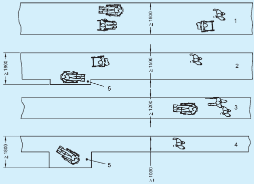
Key
1 and 2 For two-way traffic
3 and 4 For one-way traffic
5 Passing and turning space every 25 m (only acceptable for wheelchair users under exceptional circumstances)
All dimensions in millimetres.
FIG. 26 DIFFERENT SURFACE WIDTHS OF THE PATH DEPENDING ON TRAFFIC
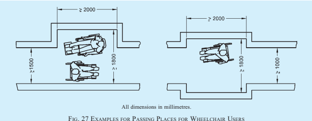
FIG. 27 EXAMPLES FOR PASSING PLACES FOR WHEELCHAIR USERS
side of a flight of steps consisting of two or more risers and each riser shall be not more than 150 mm high. A handrail shall be provided on both sides of a channel that can subdivide a flight of steps. For requirements of handrails, reference shall be made to B-5.5.2.
The cross-fall of a level or sloped path, a stepped path, a ramp, or a landing, that is provided to permit drainage of surface water, shall be in accordance with B-2.2.1(e).
The top, bottom and landings of steps and ramps shall be properly drained in order to avoid water flowing down steps and ramps.
A dished channel should not be constructed within the boundaries of a path or ramp. Dished channels shall have a maximum width of 150 mm and a maximum drop into gulley of 5 mm.
A drainage grating that is within the boundaries of a path or a ramp shall be set flush with the surface (see B-2.4).
Providing protection at the side of the path protects people who use wheelchairs and ambulant people from injuring themselves as the result of a fall. Examples of protection against falling are shown in Fig. 28.
a) If a level or sloped path is bounded on one or both sides by terrain that slopes downwards by up to 30° from the horizontal, a firm and level margin of at least 600 mm shall be provided at the relevant side or sides.
b) If a sloped path or ramp is bounded on one or both sides by terrain that slopes downwards by more than 30° , an upstand of minimum height of 150 mm shall be provided at the relevant side or sides. Upstands shall have a minimum difference in LRV of 30 points in relation to the ramp.
c) If a path, or a sloping path, stepped path, ramp, terrace or other unfenced platform rises more than 600 mm above the adjacent ground, it shall be provided with guarding. If the adjacent ground is firm and level with the path for 600 mm, no guard is needed.
Guarding shall be designed to discourage a user, particularly a child, from climbing on it.
B-2.3 Kerb Ramp/Dropped Kerb
It is a ramp built on a footpath or pavement to accommodate the change in level towards vehicular areas to allow easy and continuous access. Kerb ramps shall be provided at pedestrian crossings and at each end of the footpath of a private street or access road.
Kerb ramps shall be provided where the vertical rise is less than 150mm. They shall meet the following requirements:
a) They shall have a slip-resistant surface.
b) They shall avoid raised traction strips in order to reduce the hazard to everyone.
c) They shall be designed not to allow water accumulating on the walking surface.
d) Handrails may not be provided with kerb ramps.
e) They shall not project into the road surface.
f) They shall be so located and also protected to prevent obstruction by parked vehicles.
g) They shall be free from any obstruction such as signposts, traffic lights, etc.
h) They shall not encroach into a roadway, as it is dangerous for users and obstructive for vehicles.
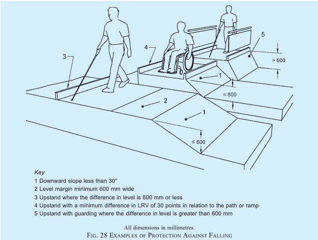
2 Level margin minimum 600 mm wide
3 Upstand where the difference in level is 600 mm or less
4 Upstand with a minimum difference in LRV of 30 points in relation to the path or ramp
5 Upstand with guarding where the difference in level is greater than 600 mm
j) They shall be so located to enable users to have an unobstructed view of traffic approaching from any direction.
k) They shall be provided with adequate visual and tactile warning.
m) TGSI (warning type) shall be provided to notify the presence of traffic and shall have a minimum luminous contrast of 70 percent with the adjoining surfaces for the elderly and persons with visual impairment.
Typical kerb ramp requirements and kerb extension at street intersections are shown in Fig. 29 and Fig. 30.
The gradient of a kerb ramp shall not be steeper than 1:12.
The kerb ramp shall not be less than 1200mm in width. It shall provide a clearance of at least 800mm at the back of the kerb ramp on the footpath (see Fig. 29).
Kerb ramps shall have flared sides where pedestrians are likely to walk across them as shown in Fig. 29 and the gradient of the flared side shall not be steeper than 1:10.
B-2.4 Levels, Grooves, Gratings and Manholes
Vertical level changes up to 6mm may not need edge treatment. Changes in level between 6mm and 12mm shall be levelled off with a slope no greater than 1:2.
The edge shall be rounded off or bevelled.
Gratings and manholes should be avoided on walkways/pathways. If unavoidable, gratings shall have spaces not greater than 12 mm wide in one direction to prevent a wheelchair from getting its casters caught in a drainage ditch or grating cover. Also, the grating bars shall be perpendicular to the travel path in such a way that its longer dimension is perpendicular to the dominant direction of movement. Grating shall be flushed with finished ground level and shall be treated with a non-slip finish (see Fig. 30).
Tactile ground surface indicators or tactile guiding and warning tiles/blocks aid blind and vision impaired pedestrians negotiate the built environment, and shall be of the dimensions as given in Fig. 31.
NOTE — Alternatively, other internationally accepted tactile pattern may be accepted by the Authority.
B-2.5.1 Tactile guiding blocks indicate a correct path/route to follow for a person with visual impairment. It is recommended to install one/two rows of tactile guiding blocks along the entire length of the proposed accessible route. Care shall be taken to ensure that there are no obstacles, such as trees, poles or uneven surfaces, along the route traversed by the guiding blocks. Also, there shall be clear headroom of at least 2 100 mm height above the tactile guiding blocks, free of protruding objects such as overhanging tree branches and signage, along the entire length of the walk.
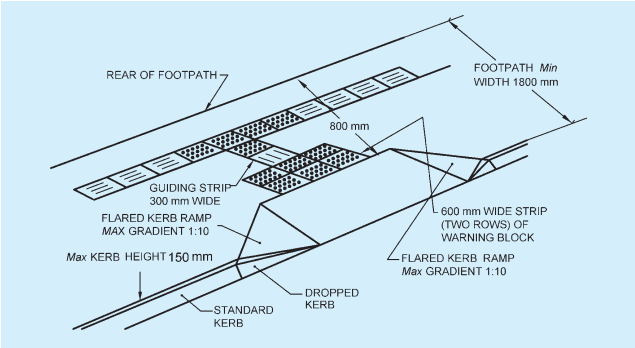
FIG. 29 KERB EXTENSION AT STREET INTERSECTION
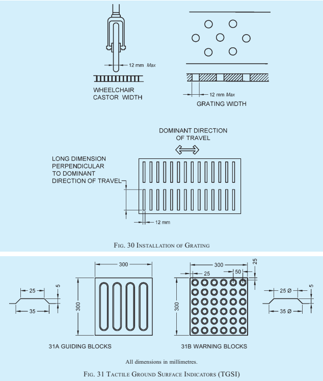
approaching potential hazard or a change in direction of the walkway, and serve as a warning of the approaching danger to persons with visual impairments, preparing them to tread cautiously and expect obstacles along the travel path, traffic intersections, doorways, etc. They are used to screen off obstacles, drop-offs or other hazards, to discourage movement in an incorrect direction, and to warn of a corner or junction. Two rows of tactile warning tiles shall be installed across the entire width of the designated accessible pathway, before intersections, building entrances, level changes, obstacles such as trees, and each time the walkway changes direction.
Warning blocks shall be placed 300 mm from the beginning and end of the ramps and stairs, at landings and entrance to any door.
B-2.5.3 Places to Install TGSI (see Fig. 32 and Fig. 33) TGSI shall be installed at following places:
a) In open space to orient persons with vision impairment;
b) In front of an area where traffic is present;
c) In front of an entrance/exit to and from a ramp, staircase or multi-level crossing facility;
d) Entrances/exits at public transport terminals
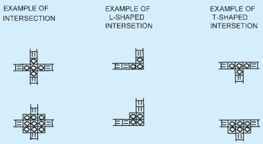
32A ARRANGEMENT OF GUIDING BLOCKS FOR PERSONS WITH VISUAL IMPAIRMENT
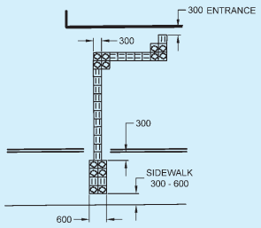
All dimensions in millimetres.
32B GUIDING PATH AND APPROACHING SIDEWALK TO THE BUILDING FIG. 32 INSTALLATION OF TGSI
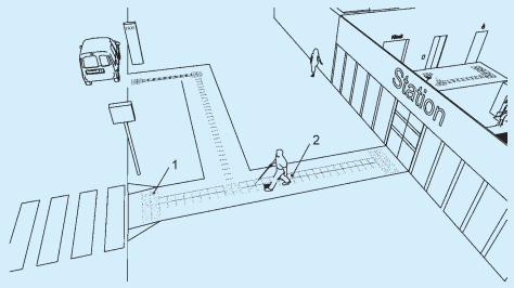
1 Tactile ground surface indicator as attention pattern for decision points or hazards 2 Tactile ground surface indicator as guiding pattern
FIG. 33 EXAMPLE OF TACTILE GROUND SURFACE INDICATORS USED IN OPEN AREAS
Key
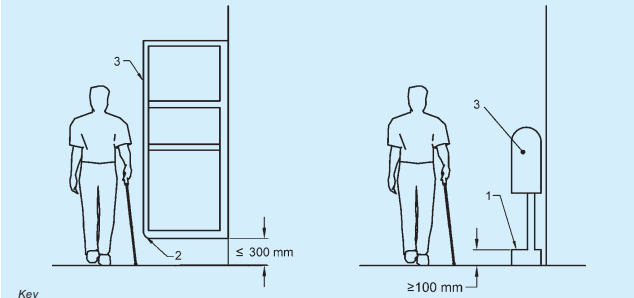
1 Base plinth detectable with cane if a projecting object is more than 100 mm above floor level
or boarding areas;
e) Sidewalk/footpath section of an approach road to a building; and
f) From a public facility to the nearest public transport station.
B-2.6.1 Obstacles, such as objects or signs mounted on walls, columns or free-standing supports along the walking path shall be avoided. Unavoidable free standing posts or columns within access routes on pathways shall leave at least unobstructed walking width of 1 000 mm and be clearly marked with visual indicators. Visual indicators at least 75 mm in height with a minimum visual contrast of 30 points difference in the LRV value of the colours to the background shall be placed; one at a height between 800 mm and 1 000 mm above floor level, and the other between 1 400 mm and 1 600 mm above floor level.
Bollards, short vertical posts generally arranged in a line to guide traffic and protect from vehicle intrusions, shall have a maximum height of 1 000 mm. Bollards, where installed within the access route shall have a minimum clear spacing between them of 1 000 mm so as to provide clear passage width for movement of wheelchairs.
Unavoidable protruding objects shall not reduce the minimum clear width of an accessible route or manoeuvring space. Protruding objects in the access route shall contrast visually with the background environment.
Objects with a height lower than 1 000 mm can create a hazard for blind or partially sighted people. Permanent equipment that cannot be located outside the boundaries of a path shall be,
a) designed to be easily seen with a minimum difference in LRVs of 30 points to the background;
b) shielded to protect against impact; and
c) accompanied by a feature that warns of the presence of a potential hazard and is detectable for a person using a white cane or stick (see Fig. 34).
The headroom along a path shall be maintained at a height of not less than 2 100 mm above the surface of the path.
Any objects projecting more than 100 mm between 300 mm and 2 100 mm above ground level into an access route shall be clearly visible and detectable with a cane (see Fig. 34).
When a projecting obstacle exists, a protective guard shall be provided at ground level, under the projecting object, such as, a kerb or fixed element at a height of 100 mm-300 mm as cane detection. Cane detection shall not be set back more than 100 mm from the face of the projecting object. Wing walls, side partitions, alcoves or recesses are solutions for projecting elements where free space under the object is needed. Winged protection shall extend continuously between 300 mm and 1 000 mm above the floor and shall contrast visually with the background.
Where headroom is less than 2100mm from the
2 Winged protection between 300 mm and 1 000 mm above floor level, contrasting visually with the background and detectable with a cane
3 Difference in light reflectance value to background – minimum 30 points
FIG. 34 SOLITARY OBSTACLES
finished floor level, a warning guardrail or other suitable barrier shall be provided for detection, having its leading edge at or below 680 mm above the finished floor level, such as to enable easy detection with a white cane (see Fig. 35).
Appropriate identification of specific facilities within a building used by the public is particularly essential to the persons with visual impairments. Raised letters or numbers shall be used to identify rooms or offices. Such identification shall be placed on the wall, to the left of the door, preferably at a height of 1 500 mm from the floor and comply with the requirements given in B-24.
Following requirements with respect to warning signals near barriers shall be complied with:
a) Audible warning signals shall be accompanied by simultaneous visual signals for the benefit of those with hearing disabilities.
b) Visual signals shall be accompanied by simultaneous audible signals for the benefit of the blind and visually impaired people. To assist blind people, lettering and symbols on signs should be raised for tactile reading.
c) Information based on colour codes only should be avoided; colour blind people may find them difficult to understand.
d) Signs should be designed, located and illuminated as per B-24.
B-2.6.6.1 Where hazards on the direct line of pedestrian
travel such as stairs, escalators and moving walks or ramps with a slope of more than 1:16 cannot be avoided, tactile warning indicators and visual markings shall be provided. Every effort shall be exercised to obviate hazards to persons with disabilities.
B-2.6.6.2 Access panels in walls or manholes in walks, may be extremely hazardous, particularly when in use/open, and shall be avoided. When manholes or access panels are open and in use, or when an open excavation exists on a site, particularly when it is in proximity of normal pedestrian traffic, barricades shall be placed on all open sides, and warning devices shall be installed.
Lighting for walkways shall be as given below:
a) Lighting should illuminate the walkway; lighting fixtures not exceeding a height of 4 m from ground level should be provided.
b) Lighting shall be provided every 20 m to 30m, focusing light not on the car lanes, but on the walkways.
c) A white light source, for example high-pressure sodium, is preferable in city and town centres for the aesthetic effect and for better colour definition, which benefits those with poor sight.
d) White lighting at average 35 to 40 lux is recommended to ensure colour contrast of tactile blocks and to ensure visibility at night to persons with low vision.
e) Light pole may preferably be located within the tree-planting zone.
f) Lower level light poles are preferred to avoid shadow where there are high trees.
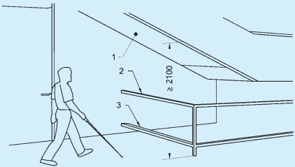
Key
1 Minimum 2100 mm clear height
2 Guardrail against impact, at a height 680 - 700 mm above floor
3 Guardrail detectable with cane, at a maximum height 300mm above floor
All dimensions in millimetres.
FIG. 35 WARNING GUARDRAIL IN CASE OF INSUFFICIENT HEADROOM
B-3 Designated Accessible Parking Space
The designated accessible parking spaces that serve a building shall be located as near as possible to the main entrance, and the distance from the accessible parking space to the main entrance shall not be more than 30 m. In case the access is through lift, the parking shall be located within 30 m of the lift lobby. Kerb ramp from parking space to an adjacent higher pedestrian path shall be provided in accordance with B-3.6.
Where indoor parking is provided, a suitable passenger lift or separated pedestrian ramp shall be installed to provide access from the parked vehicle to the principal entrance of the building or buildings served by the car parking.
The following minimum requirements concerning the number of parking places shall apply:
a) A minimum of one accessible designated parking space shall be provided in every parking area;
b) For up to 10 parking spaces, one designated accessible parking space shall be provided;
c) For up to 25 parking spaces, two designated accessible parking space shall be provided;
d) For up to 50 parking spaces, three designated accessible parking spaces shall be provided;
e) For up to 100 parking spaces, four designated accessible parking spaces shall be provided;
f) For up to 200 parking spaces, six designated accessible parking spaces shall be provided; and
g) For over 200 parking spaces, six designated accessible parking spaces for 200 parking spaces and one for each additional 100 parking spaces shall be provided.
In specialized facilities such as health care facilities, shopping areas and recreational facilities, a greater number of designated accessible parking spaces should be considered.
Signage for designated accessible parking spaces shall meet the following requirements:
a) International symbol of accessibility shall be displayed at approaches and entrances to car parking to indicate the provision of accessible parking lot for persons with disabilities within the vicinity.
b) Directional signs consisting of arrows combined with the international symbol of accessibility shall be placed along the route leading to the accessible parking lot (see Fig. 36).

FIG. 36 DIRECTIONAL SIGNAGE LEADING TO DESIGNATED ACCESSIBLE PARKING SPACES
c) Directional signs shall also be displayed to direct persons with disabilities to the accessible parking lot at points where there is a change of direction, or where the location of the accessible parking lot is not obvious or is distant from the approach viewpoints.
d) Accessible parking lot shall be identifiable by the International Symbol of Accessibility placed vertically. The signs shall not be obscured by a vehicle parked in the designated lot.
e) A vertical sign shall be provided, and to make it easily visible, the sign shall be at a minimum height of 2 100 mm. This height is to ensure that the sign does not get hidden behind large vehicles in the parking (see Fig. 37).
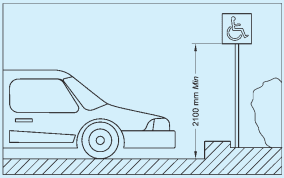
FIG. 37 VERTICAL SIGN AT DESIGNATED ACCESSIBLE PARKING SPACES
f) International symbol of accessibility shall be clearly marked/painted on the floor surface of the designated accessible parking lot for
drivers/riders with disabilities only. The symbol painted on the designated lot shall comply the following:
A square with dimensions of at least 1 000 mm but not exceeding 1 500 mm in length;
Located at the centre of the parking lot; and
Colour of the symbol shall be in contrasting colour scheme of blue and white (see B-24.2.16 and Fig. 105).
The car park entrance shall have a height clearance of at least 2 600 mm.
If payment machine is provided, it shall provide all control at the height between 800 mm and 1 000 mm (see B-7).
Access to the machine shall be level along an accessible route and easy to operate. The machine shall be located so that it does not create a hazard or barrier for persons with disabilities.
The accessible car parking space shall meet the following requirements:
a) The minimum width of the parking space for
a car shall be 3 900 mm and the minimum length shall be 5 400 mm. This minimum width includes the transfer area beside the car with a minimum of 1 500 mm.
b) Two accessible parking spaces with one shared transfer area are widely used and shall have a minimum width of 6 300 mm (see Fig. 38).
c) It shall have a firm, level surface without aeration slabs.
d) Wherever possible, it shall be sheltered.
e) The transfer zones, both on the side and the rear should have yellow or white cross-hatch road markings (see also Fig. 38).
f) The designated accessible parking spaces shall be located on a gradient not greater than 1:50, throughout its length and its width.
g) The accessible route of 1 200 mm width shall be provided for wheelchair users to pass behind vehicle that may be backing out (see Fig. 39).
h) Parking space along the footpath/sidewalk — For road side parking of an accessible van, the minimum dimensions shall be 9 000 mm × 2 400 mm with a kerb to access the nearest footpath/sidewalk (see Fig. 40).
j) Van parking with auxiliary movable ramps — The size and design of accessible vehicles may
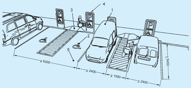
Key
1 Minimum unobstructed height for vans 2 600 mm
2 Symbol of accessibility
3 Kerb ramp
4 Signage, including symbol of accessibility
5 Firm ground
All dimensions in millimetres.
FIG. 38 ACCESSIBLE PARKING SPACES ACCESSIBLE PARKING SPACES WITH ONE SHARED TRANSFER AREA
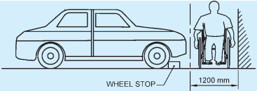
FIG. 39 ACCESSIBLE ROUTE WIDTH FOR WHEELCHAIR USERS TO PASS BEHIND A PARKED VEHICLE
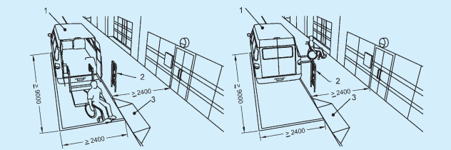
Key
1 Minimum unobstructed height — 2 600 mm
2 Signage, including symbol of accessibility
3 Kerb ramp
FIG. 40 PARKING SPACE ALONG A FOOTPATH/SIDEWALK
vary as some are fitted with ramps or hoists at the side or at the rear. The minimum width of the accessible parking space for a van shall have at least the same dimensions as for car parking spaces (see Fig. 37). Transfer areas between spaces may be shared.
For multi-purpose vehicles with hoists or lifts, more space is needed; at least an additional 2 400 mm area beside the van and/or at the rear of the van may be required. The dedicated parking space in this case shall be 4 800 mm wide and 9 000 mm long (see Fig. 38 and Fig. 40 for different types of designated parking spaces). As an alternative, a parking space of 2 400 mm wide × 9 000 mm in length along a footpath may be used, provided the footpath is at least 2 400 mm wide as shown in Fig. 39.
The kerb ramp should be located in close proximity to the designated accessible parking area connecting the accessible path of travel to the main entrance. The kerb ramp width should be a minimum of 1 000 mm. The gradient of the kerb ramp should consider the
requirements in B-2.3. Kerb ramps shall have a slip-resistant surface. The accessible path to the kerb ramp can be marked with hatching painted on the road surface to prevent people from parking in this area (see Fig. 38).
The entry to the building shall be facilitated by the following:
a) Space should be provided for passenger drop-off points for taxis, public transport and also for large vehicles such as vans, etc, as near as possible to the main accessible entrance. Vehicle drop-off areas should be a minimum of 9 000 mm in length, have a minimum width of 3 600 mm and be served by a kerb ramp.
b) At least one accessible route leading to an accessible entrance of the building shall be provided from the alighting and boarding point of taxi stands and car park lots (see B-3) for people with disabilities.
c) If there is a difference in level between the carriageway and the footpath, a kerb ramp conforming to B-2.3 shall be provided to facilitate the setting-down of people close to
the main entrance of a building. This benefits people who need to transfer to and from a wheelchair and others.
An appropriate tactile ground surface indicator (TGSI) should be provided to lead vision impaired persons to the main entrance where no other clues indicate the path to the building.
d) Building shall have all accessible entrance doors complying with B-5.3.
e) The accessible entrance, if different from the main entrance, shall be located adjacent to the main entrance and not at the rear of the building. The accessible entrance shall be clearly signed and easy to locate.
f) Symbol shall be displayed at all other non-accessible entrances to direct persons with disabilities to the accessible entrance.
B-5 Access at Entrance and Within the Building
a) Access to the building entrance shall be in accordance with B-4.
b) A clear, firm and level landing of at least 1 800 mm × 1 800 mm shall be provided on either side of the entrance door.
c) The width of the accessible entrance door shall not be less than 900 mm and the width of the corridors or passageways leading to and from such access door shall not be less than 1200 mm.
d) In multi-storey buildings, the accessible entrance shall have an accessible route leading to the lifts.
e) Internal floor surfaces shall be of materials that do not impede the movement of wheelchairs. If mat is provided it shall be in level with the floor finish.
f) Persons with visual impairments find it easier to locate doors if there is a texture difference in the floor around the doorway from the rest of the flooring. It is generally good practice to recess foot mats in the floor on either side of the door but care shall be taken to ensure that the top end of the mats are flush with the rest of the flooring.
g) In addition to the tactile pavers (TGSI) leading to the main entrances, beepers may be put at all main entrances to enable people with visual impairments to locate them.
h) Tactile layout plan of the building should be provided at the entrance for people with visual impairments.
j) Glazed entrance doors shall have manifestations on the glass as per B-5.3.13.
B-5.2 Internal Corridors and Accessible Routes
The main horizontal circulation design shall be level on each floor in order to ensure that the building is accessible to all people. Horizontal circulation shall be without steps. Where differences in level cannot be avoided, ramps or lifts shall be provided in accordance with B-6. Buildings should be designed, constructed and managed so that the internal layout is accessible and easily understood. All aspects of horizontal circulation, including corridors, should be designed to facilitate ease of movement for all people.
In order to avoid a tripping hazard (especially during a fire evacuation), where a raised threshold is necessary at a door opening, its maximum height shall be 12 mm, and those exceeding 5 mm shall be bevelled, and shall have a minimum difference in LRV of 30 points compared to the floor.
Routes should preferably intersect at right angles to each other and be easy to follow. To facilitate people with visual impairments, routes should have detectable cues and different visual contrast from the surroundings. For orientation and wayfinding in very complex buildings and across large areas, guidance may be provided by tactile ground surface indicators and visual, audible and tactile information, including egress and evacuation.
NOTE — Handrails can provide support for people with impaired mobility, guidance for people who are blind or have impaired vision, and can also support Braille information or tactile information.
Intensity in use of the corridor shall be a criterion when establishing the minimum width and length of the corridor (see Fig. 41). The minimum unobstructed width of corridors shall be 1 500 mm, with a preference for a width of 1 800 mm.
Where less than 1 800 mm wide, a corridor shall be provided with passing places, 1 800 mm wide and at least 1 800 mm in length at reasonable intervals. These dimensions shall be exclusive of handrails and any other projections, for example portable fire extinguishers, notice boards, etc.
Adequate circulation space, where a doorway exists, shall be provided (see B-5.3).
Changes of direction within a corridor shall have a turning circle with a diameter of 1500mm or more, clear of any obstructions (see Fig. 42).
The minimum clear height of corridors shall be 2 100 mm.
Hanging objects on walls should be avoided, except when they comply with B-2.6.2. The minimum unobstructed width shall remain 900 mm.
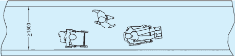
41A MINIMUM UNOBSTRUCTED WIDTH OF CORRIDOR
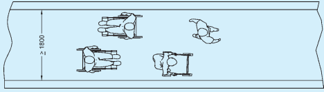
All dimensions in millimetres.
FIG. 41 DIFFERENT CORRIDOR WIDTHS DETERMINED BY THE INTENSITY OF USE
The manoeuvring zone required for a wheelchair to make a 90° turn shall be designed according to Fig. 42. It shall have no gradient, and it shall not be less than 1 500 mm wide and 1 500 mm long in the direction of travel.
B-5.2.4 Circulation Space for 180° Wheelchair Turn The space required for a wheelchair to make a 180° turn shall be not less than 2 000 mm in the direction of travel and not less than 1 800 mm wide.
For landing dimensions, see B-6.2.6.
In long paths of travel resting areas shall be provided
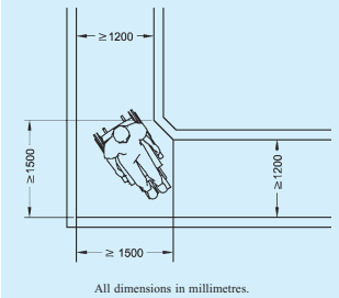
FIG. 42 SPACE REQUIRED FOR 90° TURN
at frequent intervals not exceeding 30m complying with B-2.2.1 (g).
Obstacles, projections or other protrusions shall be avoided in corridors, passageways or aisles. Long paths of travel shall be avoided and resting areas shall be provided at frequent intervals not exceeding 30 m. For provision of unavoidable obstacles and protruding objects and protection therefrom, requirements given in B-2.6 shall be followed.
B-5.2.7.1 Floor surface shall be stable, firm, level and slip-resistant, preferably of matt finish and shall not have any projections, drops, or unexpected variation in level that may impede the easy access by persons with disabilities. Following requirements shall also be complied with:
a) Complex patterns shall be avoided.
b) Floor patterns that could be mistaken for steps, for examples stripes, shall not be used for floors in corridors.
c) Floors shall be levelled. If this is unavoidable, the slope of floors shall be no greater than 1:20. If greater slope is adopted, floor shall be designed as ramp.
B-5.2.7.2 For people with low vision, lines of brightly coloured fluorescent tape may be placed on the floor surface to assist mobility in poor lighted areas.
B-5.2.7.3 Carpeting should be avoided in circulation areas/accessible routes. In case, Where, carpets are used in circulations areas, they shall,
a) not be deeper than 12mm;
b) shall be securely fixed;
c) have firm cushion, pad or backing; and
d) exposed edges of carpets be fastened to floor surface and trimmed along the entire length of the exposed edge.
Lighting in the corridor and manoeuvring zone shall be even, diffused and without glare, reflections or shadows. Minimum illumination level at the corridor and manoeuvring zone shall be 100 lux.
Doors shall conform to B-5.3 and shall not open outwards from rooms directly into a frequently used corridor, with the exception of doors to accessible toilets and service ducts. Where a door opens into an infrequently used corridor such as emergency exit, the corridor width shall allow a clear space of 900 mm within the corridor when the door is open. Such doors shall be located clear of any sloping floor surfaces in the corridor. Any door that opens towards a frequently used corridor should be located in a recess at least as deep as the width of the door leaf.
B-5.3 Doors
The doors shall meet the following general requirements:
a) Doorways shall be levelled.
b) Doorways shall be easy for people with vision impairment to locate and identify.
c) Wherever revolving doors or turnstiles are installed, they shall be supplemented with an alternate side-hung (swing type) door with 900 mm minimum clear opening width.
d) Bathroom (toilets/washroom) doors should swing out/should be two way opening type so that the person inside does not fall against the door and block it. In case there is not much space available, consideration should be given to the use of sliding or folding doors, which are easier to operate and require less wheelchair manoeuvring space.
e) Door should not be too heavy to operate and shall not require a force of more than 22 N to operate.
f) Automatic doors shall have a push button system to open them.
g) All external doors shall have warning blocks installed 300m before the entrances for aid of visually impaired users.
h) The leading edge of any door that is likely to be held open, especially those which are opening into corridors or circulation areas, shall contrast visually with the remaining surfaces of the door and its surroundings on its both sides by a 25 mm wide high-contrast manifestation, to help identification by visually impaired people. The architrave/door frame shall also contrast visually with the wall surfaces surrounding the doorway.
j) Low-hanging door closers that remain within the opening of a doorway, when the door is open or that protrude hazardously into regular corridors or traffic ways when the door is closed, shall be avoided.
k) All glazed doors shall have a highly visible contrasting frame with manifestations in a contrasting colour complying with the requirements given in B-5.3.13. Colour should contrast with the background visible through the door, whether on the inside looking out or on the outside looking in.
m) Tactile warning should be provided at approach to automatic doors complying with B-2.5.
n) Automatic doors, where provided should have guard rails, power floor mats, push or kick plate, horizontal or vertical sensing device and the doors should remain fully open until area is cleared by user. Sliding automatic doors are safer than swinging automatic doors.
p) Doors which remain ajar are extremely hazardous for vision impaired people. Doors are best fully open or completely closed; therefore, where appropriate, automatic door closure devices should be considered.
q) Entrance shall be well illuminated with even lighting between entrance and reception area.
r) Door hardware shall comply with the requirements in B-5.3.6.
B-5.3.2.1 The minimum clear opening of doorways shall be 900 mm, measured between the face of the door and the face of the door stop with the door open at 90° as illustrated in Fig. 43.
B-5.3.2.2 In case, the door has two independently operated door leaves, at least one active leaf shall comply with B-5.3.2.1.
There shall be no thresholds (doorsills). If thresholds are unavoidable, they shall not exceed 12mm and those exceeding 5mm shall be bevelled and contrast visually
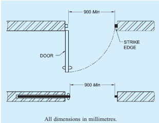
FIG. 43 MINIMUM CLEAR OPENING OF DOORWAYS
with the adjacent floor. A minimum difference in LRV of 30 points compared to the floor shall be provided.
To enable wheelchair users to approach doors, manoeuvring space as given below shall be provided. In narrow spaces, sliding doors may be preferable.
A minimum distance of 600 mm shall be provided beyond the leading edge of door to enable a wheelchair user to manoeuvre and to reach the handle.
Wheelchair manoeuvring spaces shall be free of any obstructions and be provided on the side of the door handle in the following manner (see also Figs. 44 and 45):
a) On the pull side, a minimum space of 600mm;
b) On the push side, a minimum space of 300 mm; and
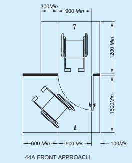
c) For two-way swing door, a minimum space of 300 mm.
The minimum space between two hinged or pivoted doors in series, shall be 1 500 mm plus the width of the door swinging into that space, as shown in Fig. 46.
Operable devices such as handles, pulls, latches and locks shall meet the following requirements:
a) They shall be operable by one hand.
b) They shall not require fine finger control, tight grasping, pinching or twisting to operate.
c) They shall be mounted at a height of 850 mm to 1 100 mm from the floor (see Fig. 47).
d) For easy identification by persons with visual impairment, all door furniture shall contrast visually with the surface of the door;
e) The location and design of latch and push/pull handles shall be consistent throughout a building.
f) To facilitate the closing of a door by wheelchair users (for example a water-closet compartment, that does not have a self-closing mechanism), the door shall have a horizontal handle, provided on the closing face of the door, approximately 760 mm from the floor.
The door handles shall conform to B-7. The following are recommended for door handles:
a) Push-pull mechanisms that require no grasping;
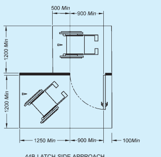
44B LATCH SIDE APPROACH
All dimensions in millimetres.
FIG. 44 MANOEUVRING SPACE NEEDED BY WHEELCHAIR USERS TO APPROACH DOORS
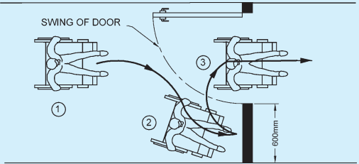
FIG. 45 POSITION TAKEN BY A WHEELCHAIR USER WHEN NEGOTIATING DOOR IN PASSAGE WAY
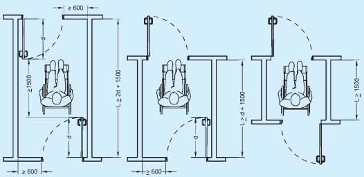
All dimensions in millimetres.
FIG.46 SPACE BETWEEN TWO HINGED OR PIVOTED DOORS IN SERIES
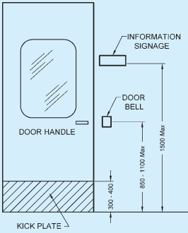
All dimensions in millimetres.
FIG. 47 DOOR HARDWARE LOCATION
b) Lever handles to be preferred on latched doors;
c) It is safer to use D-shaped handles as they reduce the risk of catching on clothing, or injuring from the exposed lever end; and
d) Doorknob is not recommended, as it does not provide adequate grip for persons with impaired hand functions.
Operating hardware should be exposed and usable from both the sides when the door is fully open.
The sweep period of the door should be adjusted, so that from an open position of 90°, the door does not take less than 3 s to move to a semi-closed position.
All two-way swing doors or doors in general circulation areas shall be provided with vision panels giving a visibility from a height of 800 mm to 1 500 mm (see Fig. 48). This will enable both the wheelchair user and the ambulatory disabled to be noticed by a person on the opposite side in order to prevent him/her from being accidentally struck by the door.
Kick-plates of not less than 300-400 mm height are recommended for doors in high-use in order to protect the push side of doors from damage (see Fig. 47 and Fig. 48).
To help people with impaired sight to see doors, the door and frame should be in a colour which contrasts with the adjoining wall. The door shall not be of a highly polished/reflective material such as stainless steel.
The presence of a glass door shall be made apparent, with permanent uninterrupted visual manifestation at two levels (hand and eye level), within 800 mm to 1 000 mm from the floor and within 1 400 mm to 1 600 mm from the floor, contrasting visually with the immediate background with a difference in LRV of 30 points seen through the glass in all light conditions (see Fig. 49). The width of the manifestation shall be minimum 75 mm. The edges of a glass door shall also be apparent when the door is open. An additional visual manifestation placed at a height of 100 mm to 300 mm is recommended (see Fig. 49). Visual manifestation consisting of two separate colours with a minimum difference in LRV of 60 points are recommended to enable lighting conditions and backgrounds to be taken into account.
If a glass door is adjacent to, or is incorporated within, a fully glazed wall, the door and wall shall be clearly differentiated from one another, with the door more prominent. To achieve this, the door may be framed on both sides and also on the top by an opaque high-contrast strip at least 25 mm wide.
Glass that is silvered or highly reflective should be avoided and any free-standing edges of glazed screens should have a strip contrasting visually with the surroundings against which they are seen.
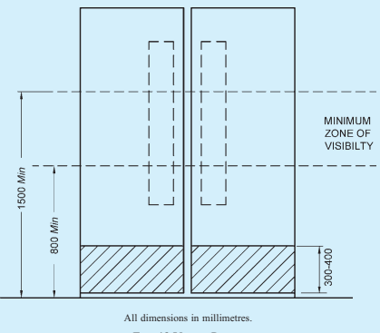
FIG. 48 VISION PANEL
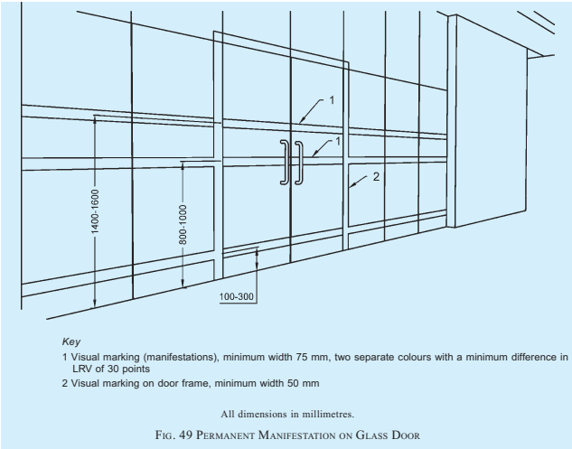
The windows shall meet the following general requirements (see Fig. 50):
a) Windows shall have handles/controls in accordance with B-7 and B-5.3.7.
b) They shall provide an unobstructed viewing zone for wheelchair users between 600 mm and 1 400 mm.
c) Curtain or venetian blind controls/ropes shall be at 800-1 000 mm height from the finished floor level for wheelchair users/short stature persons.
B-5.5 Handrails and Grab Bars
Handrails/grab bars are extremely important features and shall be designed to be easy to grasp and to provide a firm and comfortable grip so that the hand can slide along the rail without obstruction. Many persons with disabilities rely upon handrails/grab bars to maintain balance or to prevent serious falls. Handrails are used as a locational and mobility aid by persons with visual impairments and as a support for
persons with mobility impairments. The handrail/grab bars shall be securely fixed to the wall. To aid identification, the colour of the handrail/grab bar shall contrast with the wall behind.
B-5.5.2 Specific Requirements for Handrail
a) be securely fixed and rigid; the fastenings and the materials shall be able to withstand a minimum point load, both vertical and horizontal of 1.7 kN;
b) be slip-resistant with round ends;
c) have a circular section of 38-45 mm in diameter;
d) be free of any sharp or abrasive elements;
e) have continuous gripping surfaces, without interruptions or obstructions that may break a hand hold;
f) contrast with the wall behind; and
g) may be provided with Braille/tactile markings at the beginning and at the end to give information to people with visual impairment.
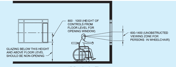
All dimensions in millimetres.
FIG. 50 REQUIREMENTS FOR WINDOWS
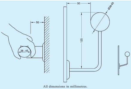
FIG. 51 HANDRAILS
B-5.5.2.2 For stepped path, stairs and ramps, handrails shall meet the following requirements (see Figs. 52, 53 and 54):
a) They shall be provided on both the sides;
b) They shall be continuous, even at the landings;
c) They shall extend at least 300 mm beyond the first and last nosing. A handrail shall not project into a transverse circulation path unless it is continuous and intended to form part of the guidance along that path. The end of the horizontal extension should be turned towards the wall on the closed side of the ramp or stairs, or be turned down and terminate at the floor or ground level.
d) They shall have a minimum clear space of 50mm from the walls; and
e) The height to the top of a handrail shall be between 850 mm and 950 mm above the surface of a ramp, the pitch line of a stair, and
the surface of a landing. A second handrail, with a lower profile than the first one, shall be provided. The height to the top of the second handrail should be between 650 mm and 750 mm above the surface of a ramp, the pitch line of a stair, and the surface of a landing. There shall be sufficient distance between the two handrails (say, 200 mm).
f) In case the handrail is enclosed in a recess, the recess shall extend at least 450mm above the top of the rail.
Grab bars shall,
a) be securely fixed and rigid;
b) be slip-resistant with round ends;
c) Preferably have knurled surfaces;
d) have a circular section of 38-45 mm in diameter;
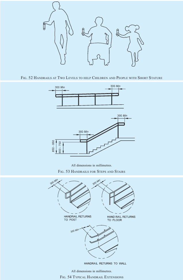
e) be free of any sharp or abrasive elements;
f) have a minimum clear space of 50 mm to 65 mm from the wall;
g) be installed at a height of 700 mm to 900 mm;
h) be able to bear a weight of 1.7kN; and
j) contrast with the wall/surface behind.
B-6 Level Changes
Vertical circulation and level changes shall be designed, constructed and managed so that they can easily be understood and used by all people. Vertical circulation includes the provision of ramps, stairs and lifts, as well as escalators, moving walks and lifting platforms.
A ramp is a sloping pathway leading from one level to another. Ramps of an appropriate design shall be provided at all changes in level other than those served by an accessible lift or accessible lifting mechanism accommodating the specific requirements of persons with disabilities.
Ramps allow persons with reduced mobility to move from one level to another. However, many ambulant persons with disabilities negotiate steps more easily and safely. Hence it is preferable to provide accessibility by both steps and ramps.
Ramps shall meet the following general requirements:
a) Wherever the rise of a ramp exceeds 300 mm, an additional flight of steps shall also be provided as described in B-6.3, shall be provided for ambulant persons. An isolated single step is not acceptable hence; a ramp is preferred to a single step.
b) Where there is a large change in elevation that requires multiple ramps and landing combination, other solutions such as lifts should be considered.
c) Ramps should not ideally connect straight to
doors as wheelchair users need a levelled platform at the end of the ramp to manoeuvre and negotiate opening the door.
d) A curved ramp is not a preferred design solution. Similarly, a cross fall may put a wheelchair user at risk and may adversely affect steering, particularly on manually propelled chair.
e) Shiny, polished surface materials that cause glare shall not be used for ramps.
f) Single row of tactile warning blocks (TGSI) shall be placed as per B-2.5 at the beginning and end of each ramp. This shall be placed 300 mm before the beginning and end of each ramp run to indicate the level change to visually impaired persons.
The gradient shall be constant between landings. The minimum specifications for ramp gradients addressing different level differences are given in Table 10 (see also Fig. 55).
The minimum clear width of a ramp (exclusive of handrails) shall be 1 200 mm and shall increase correspondingly as the level difference addressed by the ramp increases as per Table 10.
Ramps and landing surfaces shall be non-glary, smooth, level, even and slip resistant even when wet. Outdoor ramps and their surface shall be designed to prevent water from accumulating on the walking surfaces. The surface finish shall be hard and suitable for the volume of traffic that the ramp is likely to experience.
B-6.2.5 Internal ramps should, if possible, be avoided. Where required, internal ramps shall be designed in accordance with the following additional criteria:
a) No series of ramps should rise more than 2 000 mm in total. If this is the case, an alternative should be provided, for example a lift.
| Sl No. | Level Difference | Maximum Gradient of Ramp | Ramp Width mm | Handrail on Both Sides | Other Requirements |
|---|---|---|---|---|---|
| (1) | (2) | (3) | (4) | (5) | (6) |
| i) | 150 mm to 300 mm | 1:12 | 1 200 | √ | — |
| ii) | 301 mm to 750 mm | 1:12 | 1 500 | √ | Landings after every 5 m of ramp run |
| iii) | 751 mm to 3 000mm | 1:15 | 1 800 | √ | Landings after every 9 m of ramp run |
| iv) | More than 3 000 mm | 1:20 | 1 800 | √ | Landings after every 9 m of ramp run |
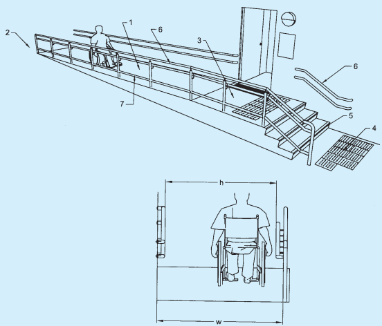
Key 1 Ramp surface (see Table 10 for maximum slope and length) 2 Horizontal landing 3 Horizontal landing 4 Tactile ground surface indicator in front of stairs 5 Complementary stairs with markings 6 Handrails on both sides of ramp and stairs 7 Upstand, Min 150 mm h Width between handrails w Width of ramp surface
FIG. 55 EXAMPLES OF RAMP WITH SLOPE 1:20 AND HORIZONTAL LANDINGS AT BEGINNING AND END
b) An internal ramp should have the lowest practical gradient. In order to avoid trips and falls during a fire evacuation, a gradient of 1:15 should be the maximum permissible gradient within a building.
c) The minimum illumination at the top and bottom of the ramp should be 200 lux and 150 lux in between the bottom and top.
An end landing shall be provided at the bottom and the top of a sloped path, a stepped path, or a ramp and also where the run changes direction. The area of the end
landing may be a part of the continuing path (see Fig. 56). The length of an end landing and an intermediate landing shall be not less than 1 500 mm. Where the ramp run changes direction, the minimum landing dimensions shall be 1 500 mm × 1 500 mm. The area of a landing shall be clear of any obstruction including the path of swing of a door or a gate.
Landings shall also be provided at regular intervals of not more than 9 000 mm of every horizontal run. It shall conform to other provisions of this annex if served by a doorway. If the end landing follows or precedes a turn for a pathway or an entrance, the minimum dimension of the landing shall be minimum 1 500 mm × 1 500 mm.
The width of ramp and consequently the dimension of landing in the direction perpendicular to the direction of ramp shall also be governed by the provisions of Table 10.
A ramp run with a vertical rise greater than 150mm shall have handrails that are on both the sides and comply with B-5.5.2.
Ramps and landings not adjacent to a wall should have an edge protection in form of a 75mm kerb. Guarding along ramps in pathway shall also meet the requirements in B-2.2.6.
B-6.3 Stairs
Steps and staircases are intended as an alternative to lift access in buildings and shall be of adequate design to allow all persons, with or without a disability, to travel safely and independently.
Stairs shall not be the only means of moving between floors. They shall be supplemented by lifts (see B-6.4) and/or ramps (see B-6.2). Staircases shall comply with the following general requirements:
a) The materials selected for the surface finish of the stairs shall be firm and slip resistant, especially if surfaces are likely to become wet due to location or use, or if spillage occurs. Slippery surfaces like granite, glazed tiles shall be avoided.
b) Shiny, polished surface materials that cause glare shall not be used for stairs or ramps.
c) Risers, treads, maximum number of risers per flight and minimum width of stairs shall be in accordance with 12.18.
d) The riser of a step shall not be open.
e) The stairs landing shall be minimum 1 500 mm deep (see also B-6.2.6). In case of one or two family dwelling units, it may be reduced to 1 200 mm.
f) Steps shall be of a consistent height and depth throughout the staircase.
g) Projecting nosing and open stairs shall not be provided to minimize the risk of stumbling.
h) Spiral stairs shall be avoided.
j) Stairs shall have handrails comply with the requirements given in B-5.5.2.
Tactile ground surface indicators (warning type) shall be installed 300 mm before the beginning and 300 mm after the end of each flight of steps to aid people with visual impairments. It shall be in accordance with B-2.5.
Tactile warning strips shall also be provided at landings. For landings leading to a floor or those enclosed by wall, railing or balustrade, tactile warning strips of 300 mm in width shall be provided; for those leading to an open space or the entrance/exit of a building, the tactile warning strips shall be 600 mm in width. In this case, Braille and tactile information signs shall be provided on the adjacent wall to indicate the presence
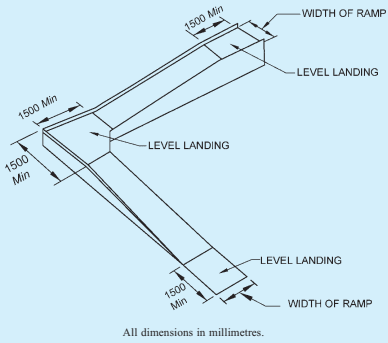
FIG. 56 LANDING DETAILS FOR RAMPS
of an opening. For a staircase with intermediate steps between two flights, the provision of tactile warning strips shall follow the same arrangement.
No appliances, fixtures or fittings shall project beyond 90 mm from the surface of any wall in a staircase below a level of 2 000 mm, measured above the treads of the staircase. If such a projection is unavoidable, the same shall also be extended downwards to the level of the treads. However, in no case the width of the staircase shall be less than that prescribed in 12.18.
There shall be colour contrast between landings, and the steps. Step edges shall contrast in colour to the risers and the treads. Contrast colour bands 50 mm wide shall be provided on edge of the tread. Illumination level of minimum 150 lux shall be maintained on the stairs.
Soffit of the stairs, shall be cordoned off either by building a wall in front of it or by putting handrails to guide persons around the space. It shall comply with the requirements of B-2.6.3 related to headroom in circulations spaces (see also Fig. 35).
B-6.4 Lifts
It is recommended that in multi-storeyed buildings there be at least one lift accessible to transport persons with disabilities at all usable levels. Such lifts shall meet the following general requirements:
a) Lift shall be located on accessible routes.
b) Accessible landings at lift entrance shall be provided on each eligible floors.
c) Lifts shall be marked with the international symbol of accessibility.
d) Directional signs indicating the location of an accessible lift shall be provided at a location that is clearly visible from the accessible building entrance. The directional signs shall incorporate a representation of the International symbol of accessibility (see Fig. 57).
e) A sign indicating the number of the floor arrived shall be provided on each lift landing on the wall opposite the lift in big fonts with good colour contrast.
f) It is recommended to install a floor directory of the main facilities and services available
on the lift landing, along with an accessible emergency egress route that clearly indicates the location of the nearest refuge area for persons with disabilities.
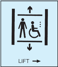
FIG. 57 WAY FINDING SIGNAGE FOR LIFT LOCATION
The minimum size of the lift shall be 1 500 mm wide by 1 500 mm deep, that allows easy manoeuvrability of wheelchair users (see Fig. 58).
The clear opening of entrance to the lift car shall be at least 900 mm. The doors shall be constructed as automatic horizontal sliding doors. The lift door shall be contrasting in colour from the adjoining wall. There shall be no difference in level between the lift door and the floor surface at each level. The gap between the lift door and building floor shall not be more than 12 mm.
A non-contact sensor device shall be provided in the door opening to detect an entering or exiting passenger or an assistive device and prevent the risk of the passenger or assistive device from being hit by the leading door panel(s). The sensor device shall cover at least 2/3 of the door height measured from a distance of 25 mm above the door sill. Time of closing of an automatic door shall be more than 5 s and the closing speed shall not exceed 0.25 m/s. The door opening time shall be adjustable to suit the conditions where the lift is installed. A mechanism to increase this time shall be installed to be customized by a user with mobility impairments (for example by means of a button outside the car to call the lift to the floor for it to arrive with extended door opening time, and a button marked with a wheelchair symbol inside the car with the same purpose). Under normal operation the levelling accuracy of the lift car shall be ±12 mm.
DOOR ENTRANCE 900 Min WAY TO LIFT 1500 Min 1500 Min 1500 Min 1500 Min 900 Min
All dimensions in millimetres.
FIG. 58 LIFT SIZE
B-6.4.4 Call Button
The call button located outside the lift shall have a clear floor space of at least 900 mm × 1 200 mm with no obstruction placed to prevent a wheelchair user from reaching the call button and shall be installed at a height between 800 mm and 1 000 mm (see Fig. 59).
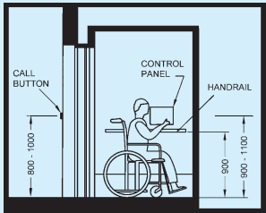
All dimensions in millimetres.
FIG. 59 PLACEMENT OF LIFT ACCESSORIES
Touch control panels shall not be used in any case as they are not accessible to visually impaired persons. The control panel inside the lift shall meet the following requirements (see Fig. 59):
a) It shall be placed at a height of between 900 mm and 1 100 mm from the floor level.
b) The control buttons may be placed either horizontally or vertically within this space.
c) It shall have buttons with Braille/raised letters and in sharp contrast from the background to aid people with visual impairments.
Handrails shall comply with B-5.5.2 and shall be placed at a height of 900mm from the floor level. These shall be fixed on both sides and at the rear of the lift.
The lift shall have a voice announcement system along with a visual display to indicate the floor level and also the information that the door of the cage is open or closed for entrance or exit. The announcement system shall be clearly audible, that is, the announcement shall be of the order of 50 dB.
In addition to the requirements given in B-6.4.1 to B-6.4.7, following requirements shall also be complied with:
a) Internal walls shall have a non-reflective matte finish in a colour and tone contrasting with the floor.
b) The floor of the lift car shall be rigid and have a non-reflective matte finish and shall be slip resistant having similar frictional qualities to the floor of the lift landing to decrease the risk of stumbling.
NOTE — A lift floor with a high LVR reassures blind and partially sighted people that they are not stepping in to an open lift shaft.
c) The provision of a mirror on the wall of the lift car opposite the lift door is a positive aid to navigation for wheelchair users. It allows
the wheelchair user to see if anyone is behind them and also to see the floor indicator panel. The mirror should not extend below 900 mm from the lift floor to avoid confusing people with impaired sight.
d) Internal car lighting should provide minimum level of illumination of 100 lux at floor level, uniformly distributed, and avoiding the spotlights.
e) Emergency warning — The car shall have an alarm device (two-way communication system) permanently connected to a manned security point according to the following:
The device shall ensure voice communication in both directions with an organization in charge of passenger rescue or with the person in charge of the safety of the building.
The operating force for alarm button shall be minimum 2.5 N and maximum 5 N.
The device shall provide visual and audible information feedback for passengers confirming that, the alarm has been sent, using a yellow enlightened bell-shaped symbol; and the alarm has been received, voice communication established, using the green enlightened symbol consisting of two heads.
For other requirements, reference shall be made to good practice [3(8)].
A fundamental objective of fire engineering design for egress is that there shall be alternative, safe and intuitive means of egress from the scene of a fire; these routes shall be available to all building users.
NOTE — Manual handling of wheelchairs occupied by their users in a fire evacuation staircase, even with adequate training for everyone directly and indirectly involved, is hazardous for the person in the wheelchair and for those people giving assistance. The weight of an average unoccupied powered wheelchair, alone, makes manual handling impractical. Evacuation chair devices can allow vertical movement on stairs of people with mobility impairments. Some evacuation chairs require a wheelchair user to transfer out of their own chair into the evacuation chair. This transfer operation requires manual handling (for example handling of one work colleague by others), and there is a risk of injury during the transfer process or if the wheelchair user uses an oxygen tube, or has a catheter or a colostomy bag. The transfer can also infringe the independence and dignity of the individual concerned.
Evacuation of occupants through assisted evacuation by use of fireman's lift should be planned while evacuation through designated lifts suitably planned and installed for use of occupants for safe evacuation are desirous to be provided.
Such lifts used for evacuation should be easily accessible, clearly identifiable and be suitably protected from the increase of smoke, heat and flame. The controls for the lift shall be located in the areas where users must wait and this area shall be designed to ensure a tenable environment provided during the entire time that the evacuation is taking place.
Such lifts should not be used for evacuation unless built for this purpose and suitably protected by the building design.
The fire evacuation shall comply with the requirements given in Part 4 ‘Fire and Life Safety’ of the Code and lifts for evacuation including fireman’s lift shall comply with the requirements given in Part 8 ‘Building Services, Section 5 Lifts, Escalators and Moving Walks: 5A Lifts’ of the Code.
Escalators and moving walks are very common in public buildings. They can greatly facilitate circulation for all building users in large, extensive and complex modern building types.
However, the location of escalators and moving walks should always be considered in relation to the position of adjacent fire protected lift shafts and lobbies, staircases and their associated areas of rescue assistance.
During normal periods of maintenance and servicing, escalators and moving walks will not be operational.
In the event of a fire emergency, building users attempting to evacuate usually tend to re-trace their routes of entry, whatever the nature of the hazard and wherever it is located. It should be assumed that the electrical supply to escalators and moving walks is terminated or turned off during such emergencies.
For important reasons of safety, therefore, inclined moving walks should comply with the requirements for ramps in buildings with respect to slope and length.
For important reasons of safety, special warning notices and indicators shall be provided at the top and bottom of escalators where step rises reduce suddenly and dramatically when not operational.
Some individuals, in particular older people, might have more than one impairment. Some individuals are not able to use an escalator or moving walk independently and rely on assistance/support being provided by a companion.
Safety shall be the prime consideration when choosing or installing escalators and moving walks.
Lifts are the preferred method of vertical travel for most people with disabilities and in particular wheelchair users.
Persons with a wheelchair generally cannot use horizontal moving walks. An inclination of up to 6° will exclude a majority of wheelchair users from using a horizontal walkway independently. Hence, alternative, like an accessible battery carts, may be provided to them in appropriate cases. Moving walks shall be free of projecting objects and obstacles up to a height of 2 100 mm. A minimum level of illumination of 100 lux shall be provided on moving walks.
A surface of the escalator that contrasts visually with the approach and the use of audible signals or prerecorded messages that indicate the start and finish of the escalator help blind and partially sighted people. Such signals or recording are not normally provided by the escalator manufacturer as standard.
Signs should be provided to indicate the location of other facilities, such as lifts, and these facilities should be in close proximity to the escalators and moving walks and be easy to find.
Reference shall also be made to other requirements given in 5.2 of Part 8 ‘Building Services, Section 5 Lifts, Escalators and Moving Walks: 5B ‘Escalators and Moving Walks’ of the Code.
B-6.6 Vertical and Inclined Lifting Platforms
Where it is impracticable or impossible to provide an accessible lift or a ramp in an existing building, vertical or inclined lifting platforms should be provided as a reasonable alternative for vertical circulation within the building. These are special passenger elevating devices for persons with disabilities. These may have either vertical or an inclined movement. These shall be able to be used safely, independently and also with an accompanying person. All control devices shall also be accessible and usable for powered wheelchair and walking aids users. If driving, guiding or lifting mechanisms present hazards at the sides of a platform, the mechanisms shall be guarded to protect the users. The guarding shall be smooth, hard and continuous.
For maximum level changes of 2 500 mm, vertical lifting platforms may be installed. For level changes of more than 1 200 mm, the lift shall be placed in a closed structure with doors at different accessible levels. Vertical lifting platforms may have a variety of openings for entry and exit.
Inclined lifting platforms consist of three elements; a railing, an electric generator and a moving platform. The operating system of the lift may be lateral or
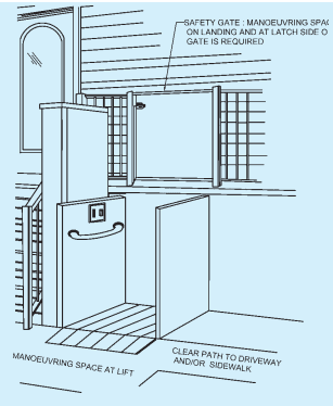
FIG. 60 VERTICAL LIFTING PLATFORMS
suspended. Inclined lifting platforms may be installed along the stair wall as long as they do not obstruct the required width of the exit. The platform may be folded when not in use.
Platform lifts may be installed on all types of stairs including switch back stairs, that is, those with a rotation of 180° and spiral staircases. Inclined lifting platforms are usually used to connect one or more floors or to overcome split levels in existing buildings.
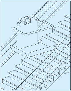
FIG. 61 INCLINED LIFTING PLATFORMS
The minimum width of the platform lift shall be 1100mm and the minimum length shall be 1400mm for the use of manual and powered wheelchairs with assistance.
In existing buildings of minor public importance and with few visitors, where sufficient space is not available, other dimensions may be considered, for example 900 mm × 1 250 mm .
B-7 Operating Controls and Devices
The design and construction of operating controls and devices should be such as to enable them to be operated safely and independently by everybody.
Operating controls and devices include, but are not limited to,
a) door handles and locks;
b) lever, mixer or cross-head taps;
c) activation devices;
d) window openers and locks; and
e) electric outlets and switches.
The operable part of controls shall be located adjacent to the clear floor space. Controls should be easy to use, for example by hands-free operation or by a closed fist or using the elbow. Minimum manual effort should be required, as for opening and closing doors.
All switches and controls should be easy to understand without requiring specialist knowledge.
Sufficient lighting of the control devices and all relevant information should be provided.
Round or oval type door knobs are not suitable for people with mobility impairment, for people of small stature or less strength, and for children.
The use of photoluminiscent pictogram signs shall be provided, where appropriate.
Devices, controls (fuse boxes, switches, push-buttons, intercoms, etc), etc, shall be installed at an accessible height for reaching and operating, between 800 mm and 1 100 mm above floor level and shall be located at a minimum of 600 mm with a preference of minimum 700 mm, from any internal corner.
NOTE — As an exception, electrical wall socket outlets, telephone points and TV sockets can be located at a minimum height of 400 mm above floor level.
Requirements and recommendations on lifts landing controls and car controls shall be as per B-6.4.4, B-6.4.5 and good practice [3(8)].
Control devices placed on a horizontal surface should be placed at a height between 800 mm and 900 mm and within 300 mm from the edge of the surface.
Reading metres should be located between 1 200 mm and 1 400 mm from the floor.
Heights of switches, socket outlets, reading controls and controls on a horizontal surface are illustrated in Fig. 62.
Safety provisions as given in Part 8 ‘Building Services’, Section 2 ‘Electrical and Allied Installations’ of the Code shall be followed.
Door handles should be placed according to Fig. 63. In Fig. 63, the figure on the left shows the height of a handle for pushing or pulling the door, the middle figure shows a vertical door handle, and the figure on the right shows an example of a pull rail that may allow a wheelchair user to close the door behind him, for example in a toilet.
If fire and safety related, all controls should be intuitive and obvious to use. Wherever, fire extinguishers are provided, one fire extinguisher should have a maximum weight of 5 kg or 6 litre or even less.
Fire alarm calls should be located between 1 000 mm and 1 100 mm above floor level.
The minimum distance of the centre of switches and devices to control doors or windows, etc, shall be 600 mm from any internal corner or any projecting element (see Fig. 64) and the recommended distance is 700 mm.
Controls for powered door openers to hinged doors should be located so that the doors do not interfere with wheelchairs, canes, mobility aids, etc. Controls for powered door openers to hinged doors should be located at a minimum of 1 000 mm from the swing of the arc of the door so that the door is clear of people in wheelchairs, scooters or other assistive devices (see Fig. 65). The opening time shall be sufficient for a person using wheelchair or assisting devices to pass through the door safely before it closes.
To help people with diverse abilities, the controls as far as possible shall be operable by one hand and require no tight grasping, pinching or twisting of the wrist.
For persons with reduced dexterity or impaired vision, electrical switches should have large push plates.
Grab bars and door or window handles should be at least 80 mm long. Lever handles should be
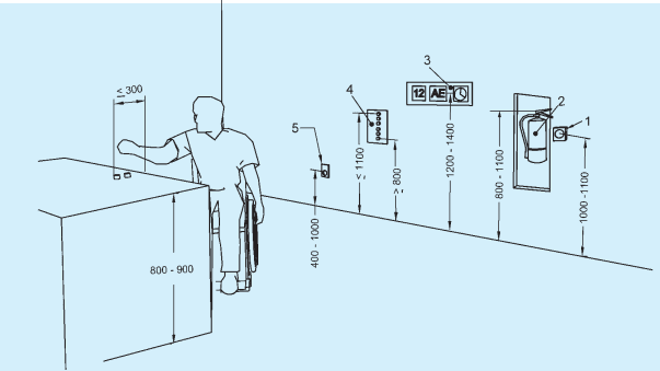
1 Fire alarm, call point
Key
2 Fire extinguisher
3 Meter indicators
4 Control devices
5 Socket outlets
All dimensions in millimetres.
FIG. 62 HEIGHTS OF SWITCHES, SOCKET OUTLETS, READING CONTROLS AND CONTROLS ON A HORIZONTAL SURFACE
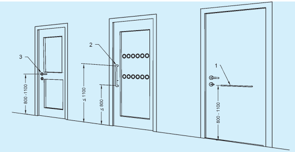
Key
1 Horizontal pull bar, toilet room door
2 Vertical handle
3 Lever type handle
All dimensions in millimetres.
FIG. 63 DOOR HANDLE TYPES AND HEIGHTS
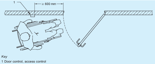
FIG. 64 POSITION OF DOOR AND ACCESS CONTROLS
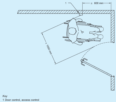
FIG. 65 DISTANCE OF CONTROLS FOR POWERED DOOR OPENERS
between 19 mm and 25 mm in diameter; 'D-Lever' handles are preferred (see Fig. 66). A vertical bar for sliding doors should be 30 mm to 50 mm in diameter. The clearance between the bar and the wall should be 45 mm to 65 mm. The backset of a latch/lock should be a minimum of 30 mm. Other door furniture should be 30 mm from the door edge. Suitable clearance should be provided between adjacent fixtures and fittings to prevent accidental operation.
Operating force on control buttons and push plates should be 2.5 N to 5.0 N. Control for drinking water
fountains shall be operable with one hand with an operative force of not more than 20 N.
Buttons and devices should be identified by visual contrast. Information should be in raised tactile and Braille signage. All important controls should have an integral Braille indication.
Control devices for different functions should be
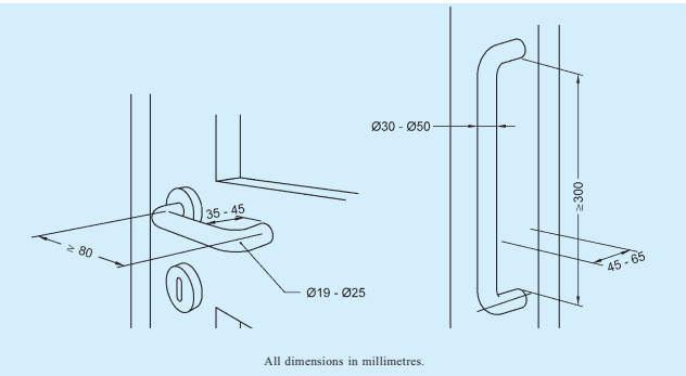
FIG. 66 EXAMPLES OF D-LEVER AND VERTICAL DOOR HANDLES
different. Control devices for similar functions should have a similar design and activation mechanism and be the same for identical functions throughout the facility.
B-7.7.1 Telephones shall be on a clear accessible route with approach from the front or the side (see Fig. 67). All information should be provided in at least two of visual, oral and tactile forms. The telephone keypad shall have a tactile point on the number five (see also B-7.9).
Public telephones shall be located beside the access route and shall be easily detected by people with vision impairments.
Where more than one public telephones are provided, at least one phone shall be accessible.
A clear knee space of minimum 700 mm in height and minimum 600 mm in depth and 900 mm in width shall be provided underneath to accommodate wheelchair user's knee (see Fig. 68).
Counter tops, where provided, shall be between 750 mm and 800 mm from the floor. The depth of the counter top shall be not less than 480 mm.
Side protection shall be considered according to B-2.6.2.
The height of all operable parts of the telephone shall be between 800mm and 1100mm. The minimum length of the telephone cord shall be 900mm.
The international symbol of accessibility shall be displayed to identify the location of such telephones.
If a public telephone is provided in an enclosed booth, the opening of the booth shall have a clear width of at least 900 mm. The enclosed space shall have clear unobstructed dimensions of at least 900 mm × 1200 mm, which should not be restricted by fixed seats.
The mail/drop box slot should be located at the height of maximum 1 200 mm. It should have a clear floor space of 900 mm × 1 200 mm.
Machines for dispensing money, tickets or small goods should be accessible and should be located on an accessible level. The approach to dispensers should be clear and unobstructed, at least 900 mm wide. A knee space of minimum 700 mm in height and minimum 600 mm in depth and 900 mm in width should be provided to ease access for wheelchair users (see Fig. 69). The clear area immediately in front of the machine should be at least 1 500 mm × 1 500 mm, to allow a wheelchair user to approach the controls sideways, and to turn around after use and to provide some privacy.
Touch screen ticket dispensers at train/bus stations, etc, should not be the only type of ticket dispenser, as they are inaccessible to people with impaired vision. A numeric keypad should also be provided to make it
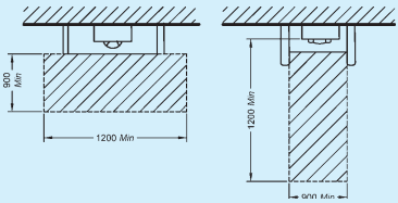
All dimensions in millimetres.
FIG. 67 SPACE ALLOWANCE FOR A WHEELCHAIR USER FOR USING TELEPHONE
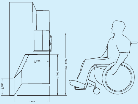
All dimensions in millimetres.
FIG. 68 HEIGHT OF TELEPHONE CONTROLS FOR WHEELCHAIR USERS
accessible for visually impaired users.
Glare from sun, artificial lighting and street lighting on the screen should be avoided.
The operation of the machine should be easy to understand.
Where card access or coin slot is provided, they shall,
a) have a slot located at a height of between 800 mm and 1 000 mm above the floor, preferably between 800 mm and 900 mm,
with its edge bevelled, and
colour-contrasted with the surrounding surface;
b) include tactile graphic symbols on the surrounding surface that,
represent the card, and
identify the orientation of the card/coin insertion; and
c) have both audible (beep) and visual (light) signals to indicate that access has been granted.
Where a keypad is provided, it shall,
be located at a height between 800 mm and 1 000 mm from the floor;
be colour-contrasted with the background;
have characters and symbols on key surfaces
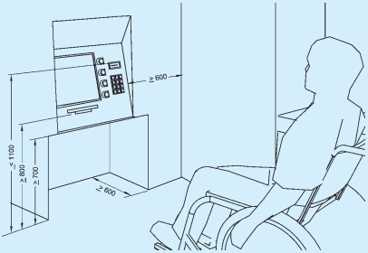
All dimensions in millimetres.
FIG. 69 EXAMPLE OF A VENDING MACHINE
that are colour-contrasted with the key surfaces; d) where numeric,
the keys shall be arranged in a 12-key ascending or descending telephone keypad layout,
the number five key shall be tactilely distinct from the other keys; the raised dot on number five shall be 0.7 ± 0.1 mm high and shall have a base 1.5 mm in diameter, and
function key surfaces shall have tactile symbols as follows: enter or proceed key: raised circle [o]; clear or correct key: raised left arrow [ ]; cancel key: raised letter × [x]; add value key: raised plus [+] sign; decrease value key: raised minus [-] sign; and
e) have both audible (beep) and visual (light) signals to indicate that access has been granted; and
f) have the keys readable from both a standing and a seated position.
NOTE — For ATMs and similar facilities, other requirements as laid down by the concerned authorities shall be followed.
Security access systems shall be designed so as to meet the needs of everyone. This includes the requirements for manoeuvring space and for controls which can be reached comfortably. See B-7.9 for requirements relating to card access and keypads. Security access systems should be usable by everyone. Biometric systems (for example retinal or palm scanners) cannot accommodate all users. To negotiate the security access systems placed at building entrances, such as, airports, railway stations, metro stations, and shopping malls,
relevant rules and regulations laid down by the concerned authorities shall be followed.
NOTE — The requirements relating to card access and keypads shall be similar to those for ATMs as laid down by the concerned authorities.
The drinking water facility (fountains, coolers, taps, etc) shall comply with the following:
a) Wall/Post-mounted cantilevered units shall have a clear floor space of at least 900 mm × 1200 mm as shown in Fig. 70.
b) The front edge of the unit shall extend 430-480 mm from the wall. It shall have a clear knee space between the bottom of the apron/equipment and floor or ground of at least 900 mm wide, 200 mm deep extending from the front edge of the equipment to back towards the wall, and 700 mm high. It shall have a toe space not less than 900 mm wide, 300 mm high, extending from the back wall to a maximum of 150 mm (see Fig. 70).
c) Freestanding or built-in-drinking water units not having a clear space under them shall have a clear floor space of at least 1 200 mm wide × 900 mm in front of the unit as shown in Fig. 71.
d) Spout heights should be between 800-900 mm, measured from the floor to the spout outlet. The maximum distance of the spout from the front edge of the drinking water facility shall be 125 mm. There shall be water glass provision; a minimum 100 mm space below the spout outlet shall be provided to allow for the insertion of a cup or glass.
e) Wall-mounted drinking water provision in an alcove is preferred, because it does not create
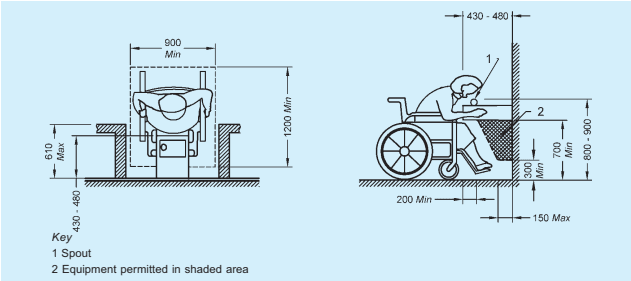
All dimensions in millimetres.
FIG. 70 CLEAR FLOOR SPACE AND KNEE SPACE REQUIREMENT FOR A WALL/POST-MOUNTED DRINKING WATER UNIT
a hazard for persons with visual impairments. The provision of two drinking facilities at different heights is very convenient for standing adults, people in wheelchairs and children. Where only one is provided, it shall be at a height of 700 mm above floor level
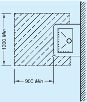
All dimensions in millimetres.
FIG. 71 CLEAR FLOOR SPACE FOR FREESTANDING OR BUILT-IN DRINKING WATER UNIT NOT HAVING CLEAR SPACE UNDER THE UNIT
Dust bins should be fully accessible and easy to use for everybody.
B-8 Seating Spaces
Seating facilities should be provided in public
buildings to provide people with a place to wait and to rest. The location of seats (including reserved areas for wheelchairs) should not disturb the general circulation.
Seating facilities shall have a clear and level floor space of not less than 900 mm × 1 200 mm.
Seats should be designed with armrests to facilitate sitting down and standing up. The seats should also have back rests (see Fig. 72).
A range of different types of seating should be provided complying with the following (see Fig. 72):
a) Seat height 400 mm to 450 mm,
b) Back support height 750mm to 790mm,
c) Seat depth 400 mm to 450 mm,
d) Angle of seat to backrest 100° to 105°,
e) Armrest height 220 mm to 300 mm above seat,
f) Armrest set back from front of seat ≤ 75 mm, and
g) A minimum 150mm set back under the seat for feet when standing up.
To allow a frontal approach with a wheelchair to a table, desk, counter, telephone, etc, an unobstructed space shall be provided with a minimum free height of 700 mm, minimum free depth of 600 mm (see Note) and minimum width of 900 mm to accommodate knees underneath. For footrests, a minimum height of 300 mm is required (see Fig. 73).
NOTE — This may overlap the clear floor space by a maximum of 480 mm.
If tables with fixed seats are used, there shall be a place for at least one person in a wheelchair at the table.
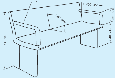
1 Armrests omitted on some benches to allow lateral transfer
All dimensions in millimetres.
FIG. 72 EXAMPLE OF A BENCH WITH ARMRESTS AND BACK SUPPORT
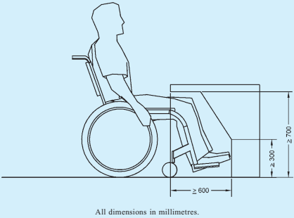
FIG. 73 TABLE AND DESK HEIGHT FOR WHEELCHAIR USERS
Sanitary facilities shall be designed to accommodate a variety of users. Accessible toilets that can be used by both sexes (unisex accessible toilets) allow the greatest flexibility for people who require assistance hence is the preferred option. Wheelchair accessible unisex toilets should always be provided in addition to wheelchair accessible separate sex toilets. Similarly, a provision of an enlarged cubicle for ambulant disabled people in a separate sex toilet room can also benefit parents with children and people who need an enlarged space (for example those with luggage).
The accessible toilet room shall be located as close as possible to the entrance/reception/waiting area of the building and should be easy to find. It should not be so located that it compromises the privacy of users.
If only one toilet is decided to be provided considering the estimated requirement as per this Code, it shall be Type A unisex accessible toilet (see B-9.2 for types of toilets). Where, more than one accessible toilet is provided, different options exist.
Where sanitary facilities are provided, the following shall also apply:
a) At least one unisex wheelchair user accessible toilet room of Type A, with central placement
of WC, shall be provided, which shall always contain a washbasin.
b) One accessible toilet (Type A or Type B) in single sex toilet block (male and female section of toilet block) shall be provided depending on the footfall and space.
c) When more than one accessible corner toilet of Type B is planned, a choice of layouts suitable for left hand and right hand transfer shall be provided. In case such toilets are located in similar position on each floor of a multi-storey building, it should allow for right and left hand transfer on alternate floors. In any case, a unisex accessible toilet of Type A shall be provided on the ground floor so as to be able to meet the need for both left and right side transfers.
d) In all separate sex toilet/sanitary rooms there shall be provision for one cubicle suitable for use by ambulant disabled.
e) Where urinals are provided, there shall be urinals for wheelchair users and ambulant disabled people.
f) Where there is requirement for only one toilet or sanitary room in a building, a wheelchair accessible unisex toilet of Type A shall be provided but of a greater width to accommodate a standing height washbasin and a urinal.
g) The provision of the accessible toilets shall be such that any wheelchair user/ambulant disabled person doesn't have to travel more than 30 m on the same floor.
h) The design of toilet facilities shall incorporate ease of use for all people and location of fittings should follow a logical sequence.
j) Care shall be taken in placing mirrors and lights to avoid confusion and dazzling for visually impaired users.
k) Soap dispensers and hand towels or driers shall be placed in a convenient and logical position so that they are easy to locate, identify and use.
m) Visual contrast and lighting shall be in accordance with B-9.16.
n) An emergency assistance alarm according to B-9.12, including a reset control, should be provided in all accessible toilets and sanitary rooms.
p) If facilities are provided such as buttons or taps which operate by use of sensors, accessible signage shall be provided to explain the same.
q) Signage at accessible toilet entrance shall be as per B-9.18.
r) Tactile signs should be used beside rather than on doors to indicate ‘Ladies’ or ‘Gents’;
s) For the benefit of the persons with vision impairments, all general toilets shall have marked on plates with raised alphabets and braille put on the wall next to the door latch, preferably on the left side. An additional signage shall also be provided on the door at 1 500 mm height. See also B-24 for other requirements of signage.
t) Many persons with visual impairments find it convenient to use the toilets where internal dimensions, accessories and fixtures placement are standardized. A tactile layout of the toilet should be provided on the wall, near the latch side at 900 mm height.
u) A distinct audio sound (beeper/clapper) may be installed above the entrance door for the identification of the toilets by persons with visual impairments.
B-9.2.1 This Part gives the characteristics and requirements for the two types of wheelchair user accessible toilet rooms, namely, Type A and Type B.
The clear manoeuvring space of the toilet room shall allow frontal, oblique and lateral transfer. Type A toilet with a central placement of WC allows right and left lateral transfer, and may be more suitable when assistance is needed. Types B only allow one side transfer.
The clear manoeuvring space at floor level in front of the water-closet and the washbasin in case of Type A toilets shall be 1 800 mm × 1 800 mm , except for Type B where it shall be 1 500 mm × 1 500 mm by using the 300 mm space under the washbasin as part of the total manoeuvring space.
The minimum free clearance beside the water-closet shall be 900 mm, whereas 1 200 mm is preferred for lateral transfer and assistance.
NOTE — Minimum clearance of 900 mm accommodates only 65 percent of the wheelchair users, clearance of 1 200 mm accommodates 90 percent of all wheelchair users especially also those who use powered wheelchairs.
The minimum dimensions for a Type A accessible toilet room are 2200mm width and 2300mm depth, and the minimum dimensions for a Type B accessible toilet room are 1700mm width and 2200mm depth.
NOTE — In case of existing buildings, as part of exceptional considerations, the measures given above cannot be achieved due to technical reasons, the manoeuvring space at floor level may be reduced, but it should be recognized that such a reduction limits the number of people who can use these toilet rooms.
B-9.2.2 Type A Toilet Room with Lateral Transfer from Both Sides
B-9.2.2.1 Type A accessible toilet room has the following characteristics (see Fig. 74 and Fig. 75):
a) Lateral transfer from both sides,
b) Manoeuvring space uninterrupted by washbasin and pan,
c) Independent water supply beside water-closet,
d) Horizontal grab rails at both sides, and
e) Toilet paper dispensers on both folding grab rails.
B-9.2.2.2 Type A accessible toilet room shall meet the following requirements (see Fig. 74):
a) It shall have minimum internal dimensions 2200mm× 2300mm.
b) The layout of the fixtures in the toilet shall be such that there is a clear manoeuvring space that provides a wheelchair turning radius of 1 800 mm in front of the water-closet and washbasin in the accessible toilet unit.
c) It shall have all fixtures and utilities arranged in a manner to provide a clear space of 900 mm × 1350 mm for wheelchair users to access them.
d) It shall have clear space of not less than 900 mm wide next to the water-closet.
e) It shall be equipped with a door complying with B-9.4.
f) It shall have a water-closet complying with B-9.5, grab bars complying with B-9.6 and washbasin complying with B-9.7.
g) It shall have essential washroom accessories complying with B-9.8.
h) It shall have an alarm to seek emergency help, complying with B-9.12.
j) It shall have the toilet roll dispenser and hand water faucet mounted below the grab bars and at not more than 300 mm from the front edge of the seat and at a height between 50 mm and 200 mm from the top of the water-closet seat.
k) Cloth hooks should be set at different heights, 900 mm to 1 100 mm, and additionally at least one hook at 1 400 mm; and projecting not more than 40 mm from the wall.
m) Where possible, be equipped with a shelf of dimensions 400 mm × 200 mm fixed at a height of between 900 mm and 1 000 mm from the floor.
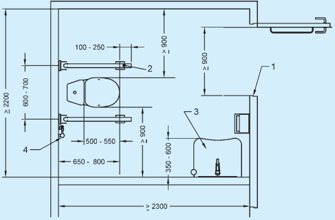
FIG. 74 EXAMPLE OF TYPE A TOILET ROOM — LATERAL TRANSFER FROM BOTH SIDES
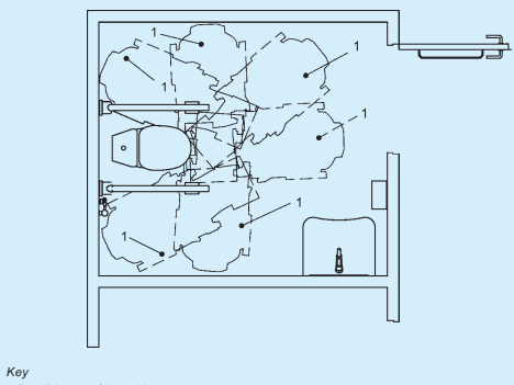
FIG. 75 TYPE A TOILET ROOM TRANSFER OPTIONS
B-9.2.3.1 Type B toilet has the following characteristics (see Fig. 76 and Fig. 77):
a) Lateral transfer only from one side;
b) Manoeuvring space reduced by washbasin;
c) Independent water supply beside water-closet, with floor drain where necessary;
d) Ability to reach small wash hand basin when seated on toilet;
e) Horizontal grab rail on wall beside the water-closet;
f) Vertical grab rail on wall beside the water-closet for getting up and sitting down (slanted grab bars are not preferred);
g) Foldable grab rail; and
h) Toilet paper dispenser fixed on the wall beside the water-closet.
B-9.2.3.2 Type B accessible toilet room shall meet the following requirements (see Fig. 76):
a) It shall have minimum internal dimensions of 1 700 mm × 2 200 mm .
b) It shall have all fixtures and utilities arranged in a manner to provide a clear space of 900 mm × 1 350 mm for wheelchair users to access them.
c) It shall have clear space of not less
than 900mm wide next to the water-closet.
d) It shall be equipped with a door complying with B-9.4.
e) It shall have a water-closet complying with B-9.5, grab bars complying with B-9.6 and washbasin complying with B-9.7.
f) It shall have essential washroom accessories complying with B-9.8.
g) It shall have an alarm to seek emergency help, complying with B-9.12.
h) It shall have the toilet roll dispenser and hand water faucet mounted below the grab bars and at not more than 300 mm from the front edge of the seat and at a height between 50 mm and 200 mm from the top of the water-closet seat.
j) Cloth hooks should be set at different heights, 900 mm to 1 100 mm, and additionally at least one hook at 1 400 mm; and projecting not more than 40 mm from the wall.
k) Where possible, be equipped with a shelf of dimensions 400 mm × 200 mm fixed at a height of between 900 mm and 1 000 mm from the floor.
These compartments meet the needs of ambulant disabled people who require support (see Fig. 78 and Fig. 79).
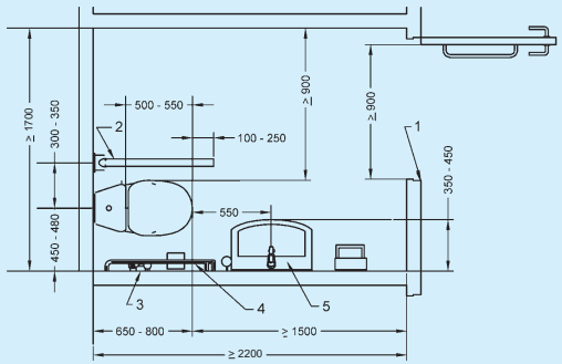
Key
1 Minimum 900 mm
2 Foldable grab bar
3 Independent water supply
4 Grab bar on wall
5 Washbasin
All dimensions in millimetres.
FIG. 76 EXAMPLE OF TYPE B CORNER TOILET ROOM — LATERAL TRANSFER FROM ONE SIDE ONLY
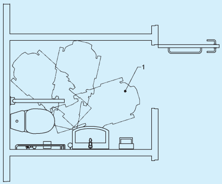
1 Possible transfer positions
FIG. 77 TYPE B TOILET ROOM TRANSFER OPTIONS
This type of compartment is not for the majority of people who use wheelchairs. When located in a single-sex washroom, hand washing facilities will be available communally. Where this is a standalone facility, hand washing facilities shall be provided either in a space adjacent to the WC compartment or in a compartment suitably enlarged to accommodate a wash hand basin.
Such WC compartments shall meet the following requirements:
a) It shall have a clear manoeuvring space of minimum 900mm× 900mm in front of the toilet.
b) It shall be equipped with a door complying with B-9.4 and opening outwards.
c) Water-closet shall comply with B-9.5.
d) Grab rails complying with B-9.6, horizontal and vertical shall be provided on both sides of toilet.
e) It shall have other toilet accessories and fittings complying with B-9.8.
f) It shall have independent water supply beside water-closet, preferably a hand held toilet spray and floor drain, where necessary (see B-9.9).
Toilet or sanitary room doors shall comply with B-5.3. The toilet door shall either be an outward opening door or two way opening door or a sliding type and shall provide an unobstructed and clear opening width of at least 900 mm; it shall be easy to open and close. There should be no openings under or above the door that compromises on privacy. Doors should be positioned so as not to constitute a hazard.
The toilet door shall be provided with a horizontal pull-bar, at least 600 mm long, on the inside of the door, located so that it is 130 mm from the hinged side of the door and at a height of 900 mm to 1 000 mm. A horizontal pull handle on the inside of the outward opening doors shall be provided at a height of 700 mm above the floor. The door shall be capable of being locked from the inside by a device that is operable by one hand, activated by a force not more than 22 N and which does not require fine finger control, tight grasping, pinching or twisting of the wrist.
Water-closet shall comply with the following requirements:
a) It shall be so located that the distance between centreline of the water-closet to the adjacent wall in case of corner toilets (Type B) be between 450 mm and 480 mm. The minimum distance of a corner toilet from the edge of the WC seat to the adjacent wall should be 250 mm. In case of Type A toilet, the distance from the edge of the WC seat to the adjacent wall shall be 900 mm, minimum on both sides to allow ease of transfer.
b) The top of the water-closet shall be between 450 mm and 480 mm from the floor.
c) The minimum distance from the front edge of the water-closet to the rear wall should be between 650 mm and 800 mm.
d) There shall be an adequate clear floor space of at least 1 300 mm depth and 900 mm width, both in front and on the transfer side, adjacent to the water-closet.
e) There shall be a suitable back support to reduce the chance of imbalance or injury
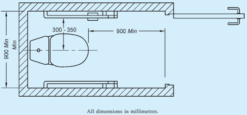
FIG. 78 TOILET FOR AMBULANT DISABLED WITH L-SHAPED GRAB BAR
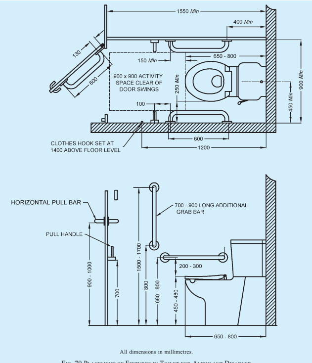
FIG. 79 PLACEMENT OF FIXTURES IN TOILET FOR AMBULANT DISABLED
caused by leaning against exposed valves or pipes. The distance from the seat to the backrest should range between 500 mm and 550 mm.
f) The water-closet shall preferably be of wall-hung or corbel type as it provides additional space at the toe level.
g) Where water cistern is used, the cover shall be securely attached and the flush control shall either be lever type or automatic, and located on the transfer side of the water-closet. The
flush control shall not be located more than 1 000 mm from the floor.
h) Toilets for children should have a distance from the centre line to the adjacent wall between 305 mm and 380 mm and the water-closet height shall be between 205 mm and 380 mm.
Grab bars complying with B-5.5.3 shall be provided in toilet or sanitary rooms in accordance with this clause.
On both sides of a toilet, a grab bar (whether drop-down or fixed to the wall) shall be provided at a distance between 300 mm and 350 mm from the centre line of the toilet.
On the sides where a lateral transfer is possible, a foldable grab bar (drop-down support bar) shall be provided at a height of 200 mm to 300 mm above the water-closet. The length of the foldable grab bar should overlap the front edge of the water-closet in between 100 mm and 250 mm. The positioning of a foldable grab bar should allow access from a wheelchair when folded up.
Where a wall is beside the toilet, a horizontal grab bar shall be provided at a height of 200 mm to 300 mm above the water-closet, and a vertical grab bar shall exceed from the horizontal grab bar to a height of 1 500-1 700 mm above floor level. The grab bar shall extend a distance of minimum 150 mm to the front edge
of the water-closet.
Alternatively, one L-shape grab bar, 600 mm long horizontal and 700-900 mm long vertical shall be mounted on the side wall closest to the water-closet, as illustrated in Fig. 80.
The horizontal grab bar shall be uninterrupted for its full length.
The positioning of accessories such as hand towel, soap, waste bin, etc, should not hamper the use of the grab bar.
The grab bar height for toilets for children should be between 510 mm and 635 mm.
A washbasin complying with following requirements shall be provided within an accessible toilet room (see Fig. 81):
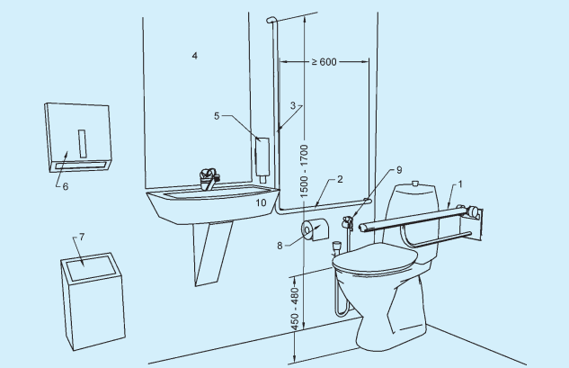
Key
1 Drop down support grab bar at seat height plus 200 to 300 mm
2 Wall mounted horizontal grab bar at seat height plus 200 to 300 mm
3 Wall mounted vertical grab bar
4 Mirror, top height minimum 900 mm, bottom height maximum 900 mm above floor
5 Soap dispenser 800 to 1 000 mm above floor
6 Towels or dryer 800 to 1 100 mm above floor
7 Waste bin
8 Toilet paper dispenser 600 to 700 mm above floor
9 Independent water supply
10 Small finger rinse basin 350 mm maximum projection
All dimensions in millimetres.
FIG. 80 POSITIONING OF GRAB BARS, WATER SUPPLY AND OTHER TOILET ACCESSORIES IN TYPE B CORNER TOILET
a) The positioning of a washbasin should allow access from a wheelchair. It shall provide a minimum clear floor space of 900 mm wide by 1 200 mm deep, of which a maximum of 480 mm in depth may be under the washbasin.
b) It shall be mounted such that the minimum distance between the centreline of the fixture and the side wall is 460 mm; and the top edge of the washbasin is between 750 mm and 850 mm from the floor.
c) The differences in stature may require lower or higher heights of washbasins and it may be advisable to have an inbuilt flexibility to increase or decrease height.
d) The space under the washbasin shall be unobstructed with a knee clearance centred on the washbasin between 680 mm and 700 mm high, and 200 mm deep. In addition, a toe clearance of at least 300 mm high shall be provided (see Fig. 82). The front edge of the washbasin shall be located within a distance of 350 mm to 600 mm from the wall, according to Fig. 74.
e) The hot water and drain pipes within the knee
space or toe space shall be properly insulated.
f) Automatic or lever type faucets/taps shall be provided complying with B-9.10.
g) In front of the washbasin, space should allow for a frontal or oblique approach by a wheelchair. The reaching distance to the tap control shall be a maximum of 300 mm, according to Fig. 82.
h) Edges on washbasins should be rounded.
j) The mirror above the washbasin shall be positioned to have the bottom edge at a height of not more than 900 mm above the floor, up to a height of 1 900 mm (see Fig. 81). If a second mirror is provided, the maximum height above the floor should be 600 mm, up to 1 850 mm. The mirror shall be tilted at an angle of 30° for better visibility of wheelchair user. Care shall be taken in placing mirrors and lights to avoid confusion and dazzling for visually impaired users.
k) A shelf with minimum dimensions of 200 mm × 400 mm should be provided near the washbasin at a height of 850 mm , or combined with the washbasin.
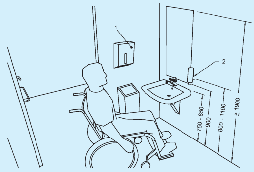
All dimensions in millimetres.
FIG. 81 PLACEMENT OF WASHBASIN AND MIRROR ABOVE THE WASHBASIN WITH DISTANCE OF SANITARY APPLIANCES
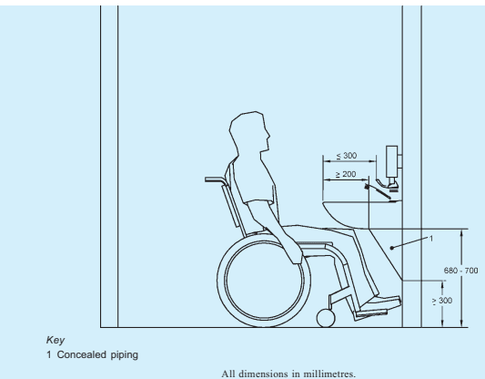
FIG. 82 WASHBASIN WITH KNEE/TOE CLEARANCE
All other fittings, for example the water tank, hand dryer, towel, soap dispensers, waste bins, hand-held shower, etc, should be set at a height between 800 mm and 1 100 mm from the floor (see Fig. 80). Coat hooks should be set at different heights, 900 mm to 1 100 mm, and additionally at least one hook at 1 400 mm. Accessories shall be placed in close proximity to the basin, to avoid a person with wet hands wheeling a chair.
Dispensers for toilet paper shall be reachable from the water-closet, either under the grab bar or on the sidewall of a corner toilet at a height between 600 mm and 700 mm from the floor (see Fig. 80).
Light switches should be fixed inside all accessible toilet cubicles or the lighting should automatically switch on when someone enters the room. Timed light switches should not be installed or used.
Needle boxes to safely dispose of needles (for example from diabetes patients) should be provided.
If a sanitary bin is supplied, it should be reachable from the water-closet. Sanitary bins with non-touch opening devices are preferred.
Non-touch soap dispensers are preferred.
An independent water supply (hand-held shower) shall be provided next to the toilet. An alternative such as a
combination bidet and rear side pan/built-in bidet can be installed.
Taps should be mixer, lever or sensor operated to aid operation, complying with requirements given in B-7. The tap controls should be set no more than 300 mm from the front of the washbasin. It is recommended that a thermostat be installed to limit the temperature of the hot water to a maximum of 40° C in order to prevent scalding. Hot and cold water taps should be identifiable by both colour and tactile markings.
Wheelchair users may be able to pull themselves to a standing position to use a urinal, or they may be able to use a urinal from their wheelchair. Ambulant persons with disabilities, for example crutch users, may need support in front of urinals. Bowl urinals are preferable to slab urinals for the benefit of visually impaired.
When wall hung urinals are fitted in the washroom, it is recommended that at least one of these have its rim set at a height of 380mm for wheelchair users and at least one have its rim set at a height of 500mm for standing users/ambulant disabled. When installed, both should be equipped with a vertical grab rail. Urinals shall be minimum 360mm deep measured from the outer face of the urinal rim to the back of the fixture.
The lower urinal position as shown in Fig. 83 is also beneficial to a person of lower stature. Where an
accessible urinal is provided, the accessible approach to the same shall be ensured. This wall hung urinal should be set clear above the floor level, without any raised access platform and with a clear floor area in front of the urinal of at least 760 mm wide and 1220 mm deep to allow forward approach for ambulant disabled and minimum of 900 mm × 1350 mm for wheelchair users to use the urinals (see Fig. 84). Urinals should contrast visually with the wall to which they are attached.
An assistance alarm, which can be reached from changing or shower seats, from the WC and by a person lying on the floor, shall be provided in all accessible toilets and accessible sanitary rooms. This alarm should
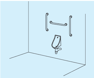
FIG. 83 URINAL FOR WHEELCHAIR USERS
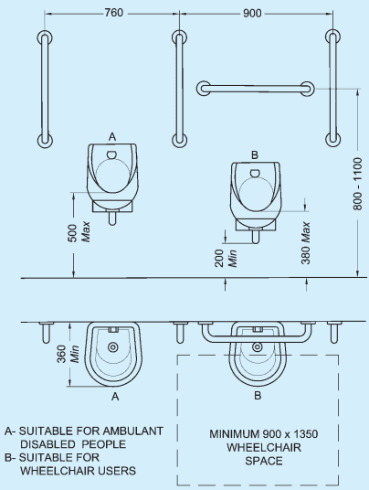
NOTE — Urinals shall be minimum 360 mm deep measured from the outer face of the urinal rim to the back of the fixture. Space below the urinal set for wheelchair users should be kept free of pipework up to a height of 200 mm above floor and up to a depth of 360 mm from the outer face of the urinal rim.
All dimensions in millimetres.
FIG. 84 CLEAR FLOOR SPACE AND MOUNTING HEIGHTS FOR URINALS
be connected to an emergency help point, or where a member of staff can assist.
Visual and audible feedback should be provided to indicate that, when the alarm has been operated, the emergency assistance call has been acknowledged and action has been taken.
It should take the form of a pull cord, coloured red, with two red bangles of 50 mm diameter, one set at a height between 800 mm and 1 100 mm and the other set at 100 mm above floor level.
A reset control shall be provided for use if the alarm is activated by mistake. It shall be reachable from a wheelchair and, where relevant, from the WC, the tip-up seat in a shower or changing facility, or the bed in an accessible bedroom. The reset control shall be easy to operate and located with its bottom edge between 800 mm and 1 100 mm above floor level.
For a corner toilet room, the reset button should be above the fixed horizontal grab rail beside the toilet paper holder.
The marking of the reset control shall be both visible and tactile.
A visual emergency alarm shall be provided to alert people who are deaf or hard of hearing in the event of an emergency.
Showers and changing rooms can be used by people with different disabilities and different supporting aids, for instance, wheelchair users, ambulant disabled people, etc, using their own wheelchairs or special shower chairs.
The shower/change area shall have level entry and have no fixed elements that prevent front and side access.
A self-contained individual shower room or changing room shall have minimum interior dimensions of 2 000 mm × 2 200 mm (see Fig. 85 and Fig. 86). See B-9.14.6 for other requirements of individual shower room.
A shower room incorporating a corner accessible toilet room shall have minimum interior dimensions of 2 400 mm × 2 500 mm (see Fig. 87). In such cases, the manoeuvring areas may overlap, as shown in Fig. 87.
The minimum clear floor space or wet showering area should be 900 mm × 1 350 mm, with a transfer area of also 900 mm × 1 350 mm in the shower room (see Fig. 88).
If two or more shower recesses are provided, at least one shall have the seat on the opposite side.
The floor in the shower recess shall have a gradient between 1:50 and 1:60 sloping to a floor drain. The area outside the shower recess shall have a gradient between 1:70 and 1:80 draining towards the shower recess.
The floor of the shower shall be slip-resistant even when wet.
The transition into the shower recess shall be level without a step down or a kerb. Where unavoidable the kerb shall not be more than 12 mm high bevelled at a slope of 1:2.
The waste outlet should be centrally located and be a round type outlet, not a channel type, to ensure the stability of the shower chair.
The shower should be fitted with a wall mounted, easily operable foldable seat that folds in an upward direction. If a foldable seat is provided, its minimum size shall be 450 mm × 450 mm , and, when folded down, have its top surface set between 450 mm and 480 mm above finished floor and spaced a maximum of 45-50 mm from the rear wall.
The shower seat shall be positioned such that the distance between the centerline of the shower seat and the adjacent wall is 450 mm to 480 mm, and the distance between front edge of the shower seat and the rear wall is 650 mm.
Enclosures for the shower cubicle shall not obstruct transfer from wheelchair onto shower seat.
The fastenings for grab bars and the construction of the foldable seat shall be able to withstand a force of 1.1kN applied at any position and in any direction.
NOTE — Shower wheelchairs are sometimes used instead of shower seats.
The foldable seat shall have the following features:
a) Self-draining;
b) Slip-resistant and stable;
c) Foldable in an upwards direction; when folded, it shall not present a hazard and the grab rail shall be accessible from the foldable seat;
d) Rounded front corners (radius 10 mm to 15 mm); and
e) Rounded top edges (minimum radius of 2 mm to 3 mm).
The foldable seat should preferably be height adjustable.
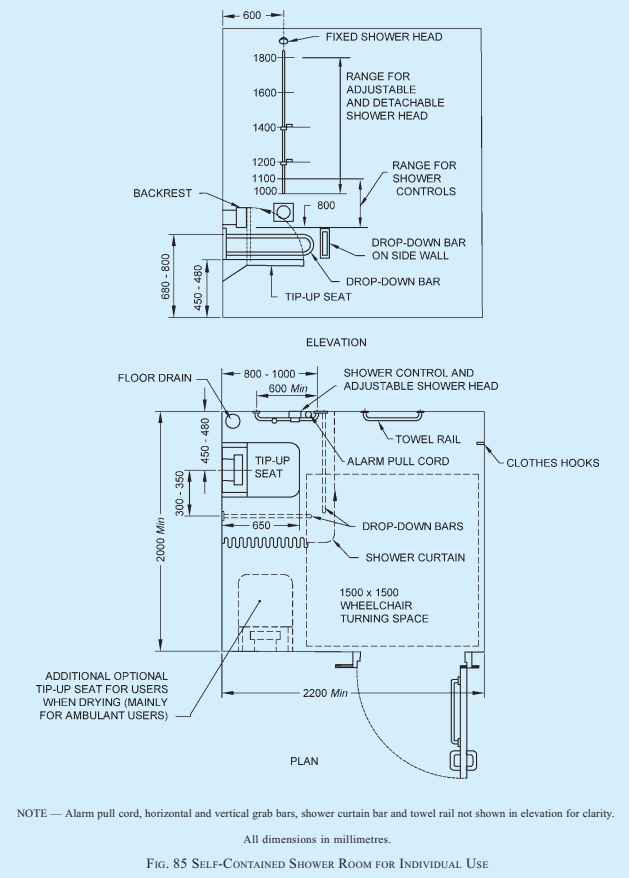
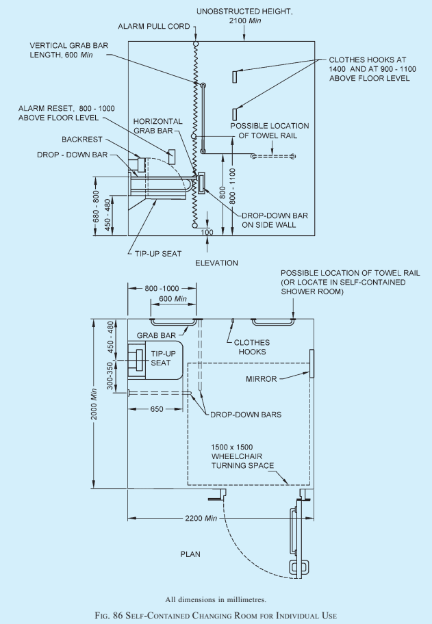
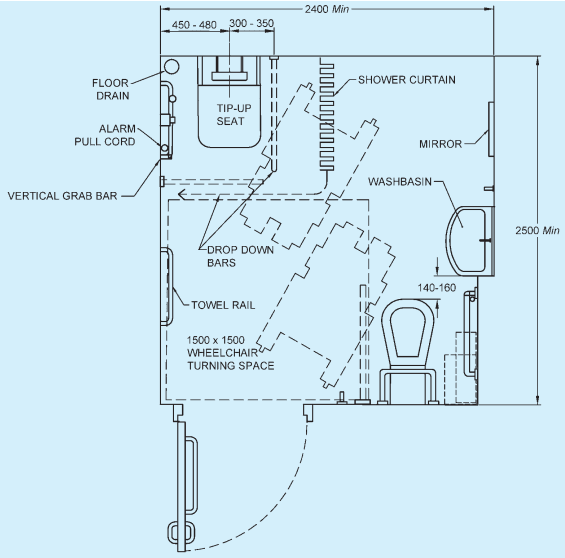
NOTES
1 Layout shown for right-hand transfer to shower seat and water closet.
2 The larger washbasin are set back 200mm to maintain the correct relationship of its leading edge with the water closet. All dimensions in millimetres
FIG. 87 SHOWER ROOM INCORPORATING AN ACCESSIBLE CORNER TOILET FOR INDIVIDUAL USE
Grab bars in shower shall be set according to B-9.6 and Fig. 87. The shower area shall be fitted with at least one vertical grab bar which may hold the flexible shower head.
The length of the flexible (adjustable and detachable) shower hose (telephone shower/ handheld shower), shall be 1 500 mm minimum. The handheld shower head should be provided between 1 000 mm and 1 200 mm above the finished floor. The shower hose fitting should be a minimum 1 300 mm above floor level.
Shower controls and folding seat shall be set according to Fig. 88. Controls shall comply with B-7.
The shower room shall be equipped with a door complying with B-9.4. Assistance alarm(s) shall be provided in accordance with B-9.12.
A clear floor space of at least 1 350 mm × 900 mm shall be provided on the clear side of the foldable seat, to allow access from a wheelchair, in addition to the manoeuvring space of 1 500 mm (see Fig. 85).
The screening of a shower recess shall be either a curtain or a door system that maintains the required circulation and manoeuvring space and does not interfere with the level entry.
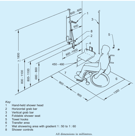
Key 1 Hand-held shower head 2 Horizontal grab bar 3 Vertical grab bar 4 Foldable shower seat 5 Towel hooks 6 Transfer area 7 Wet showering area with gradient 1 : 50 to 1 : 60 8 Shower controls
FIG. 88 EXAMPLE OF A SHOWER PLACE WITH GRAB RAILS, ADJUSTABLE SHOWER HEAD AND FOLDING SEAT
A shower head support grab bar shall be fixed on the wall in the position shown in Fig. 88.
A hand held detachable shower head shall be provided with a flexible hose of minimum length 1 200 mm, and it shall be able to reach within 100 mm of the shower floor.
An adjustable shower head holder shall be provided to support the shower head, and shall,
a) be installed on the shower head holder support grab bar as shown in Fig. 88;
b) allow the graspable portion of the shower head to be positioned at various angles and heights; and
c) allow the graspable portion of the shower head to be located at heights between 1 000 mm and 1 800 mm above the finished floor.
The fastenings, materials and construction of the seat shall withstand a force of 1.1kN applied at any position and in any direction.
Grab bars shall be fixed on the walls in the positions shown in Fig. 88. All other devices, for example taps,
soap holder, shall be situated in an accessible range between 900 mm and 1 100 mm.
Public toilets shall also comply with the overall requirements under B-9 with respect to the facilities provided therein so as to ensure that the same are accessible. In all public toilets, the following shall be provided:
a) Male section shall have one urinal with support grab bars for ambulant disabled and at least one urinal for children at a lower height;
b) Both male and female section shall have one WC for ambulant disabled;
c) One Type A unisex accessible toilet room with independent entrance; and
d) Depending on footfall, one Type B accessible toilet in both male and female toilet groups.
Fixtures and fittings in sanitary facilities should visually
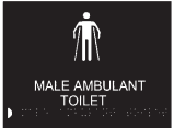
contrast with the items and surface on which they are positioned. Use of the same colour everywhere, for example white basins and white tiles, etc, shall be avoided and colour and tonal contrast should be used to differentiate elements in the environment.
Light switches should be fixed inside all accessible toilet cubicles or the light should automatically switch on when someone enters the room. Timed light switches should not be installed or used.
The minimum illumination measured at 800 mm above floor level shall be 200 lux in the area of the washbasin.
B-9.17 Floor Surface
The floor surface shall be slip resistant, anti-glare and firm.
Signage shall be clearly visible incorporating the international symbol of accessibility and shall comply with the requirements given in B-24. Signage for unisex accessible toilet, toilet for ambulant disabled, unisex change rooms or fitting rooms, unisex shower rooms shall be as shown in Fig. 89. Signage for Type B accessible toilet shall also indicate available transfer option, that is, right hand or left hand as shown in Fig. 90.
B-10 RECEPTION AREAS, COUNTERS, DESKS AND TICKET OFFICES
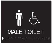
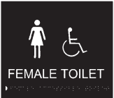
Reception areas, counters, ticket offices, especially in
UNISEX TOILET
MALE AMBULANT TOILET

FEMALE AMBULANT TOILET
UNISEX AMBULANT TOILET
UNISEX SHOWER
UNISEX CHANGING ROOM
UNISEX FITTING ROOM
FIG. 89 SIGNAGE FOR DIFFERENT SANITARY FACILITIES
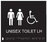
UNISEX TOILET LH
UNISEX TOILET RH
FIG. 90 SIGNAGE INDICATING TRANSFER OPTIONS (RIGHT HAND OR LEFT HAND) IN UNISEX ACCESSIBLE TOILET
noisy environments or those equipped with a separating security screen, should have at least one position fitted with a hearing enhancement system (for example induction loop system) to assist hearing-aid users, as described in B-21, and be clearly marked with the appropriate signage/symbol.
Positioning of service counters in front of windows where bright sunshine may come should be avoided as it causes the user's face to be in shadow and hence difficult to lip-read. Service counters equipped with a service screen are particularly difficult. Reflections and glare should be avoided.
Counters and reception desks should be located and clearly identified so that they are easily recognizable from a building entrance. Information reception areas should be positioned near the main entrance. Entrance flooring systems or tactile ground surface indicators can help in locating reception counters for people who have vision impairment. Such products should be designed to minimize trip and slip hazards.
General design requirements for colour and visual contrast should be considered (see B-24.3).
Counters, desks and ticket offices should be accessible to wheelchair users on both sides. A clear manoeuvring space at least 1500mm × 1500mm shall be provided in front of the counter on the receptionist's side and on the visitor's side; 1800mm × 1800mm is preferred.
B-10.4.1 The counter level shall be between 750mm
and 800 mm from the floor. Clear knee space underneath shall be minimum 700 mm (see also Fig. 91).
B-10.4.2 Reception desks where writing is done by the visitor (for example at hotel receptions) should allow frontal approach by wheelchair users with space to provide clearance for wheelchair user's knees. The counter level and clear knee space underneath shall be as per B-10.4.1. At least a part of the desk should also be at a height suitable as a writing place for standing people, between 950 mm and 1 100 mm (see Fig. 91).
To facilitate lip reading, lighting should provide even illumination. The reading and writing surfaces at counters, desks and ticket offices shall be illuminated to a level of at least 200 lux in the room, and on the desk in a range of 350 lux to 450 lux.
If a queue number ticket system is used, it shall be suitably designed to be accessible. All control devices shall be located according to B-7. All necessary information shall be given in simple wording with sufficient visual contrast and based on the two-sense-principle (see B-7, B-21, B-24.1.2, and B-24.3). The ticket machine and the calling system shall provide visual and audible output.
Attended cloakrooms are staffed rooms where bags/luggage/other articles can be stored securely. Typically, a ticket or receipt is given to the customer, with a
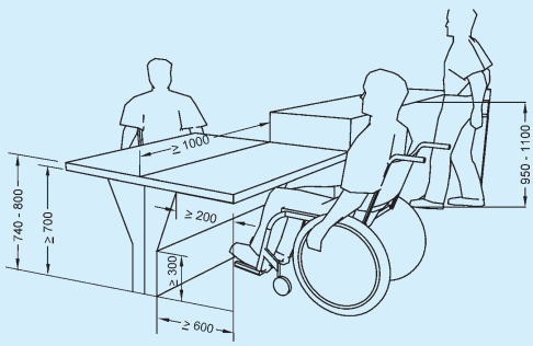
All dimensions in millimetres.
FIG. 91 HEIGHTS OF COUNTERS SUITABLE FOR WHEELCHAIR USERS AND PEOPLE STANDING
corresponding ticket attached to the garment or item. A cloakroom shall comply with the requirements given for reception/counters (see B-10).
B-12 Auditoriums, Concert Halls, Sports Arenas and Similar Seating
A hearing enhancement system should be provided. The system should also be provided on the stage/platform (see B-21).
Adequate provision should be made to facilitate sign language and lip reading. Lighting on the faces and hands of presenters and people signing should be provided at an angle of 45° to 50° from horizontal at ceiling level for people with a hearing impairment to be able to read the presenter's lips and the signer's lips and hands. A suitable contrasting backdrop should be provided, to assist in reading the presenter's lips and hands.
At least 1 percent of seats shall be designated as seating areas (see B-8 for requirements of seating spaces) for wheelchairs users, with a minimum of two.
For total seats exceeding 51, it is recommended to provide the designated seating areas in the following manner:
a) Total seats 51 to 100, minimum three designated seating areas for wheelchair users;
b) Total seats 101 to 200, minimum four designated seating areas for wheelchair users; and
c) One additional seating area should be provided for every two hundred additional seats or part thereof.
These spaces should be integrated among other seats and allow two wheelchair users to stay together. It is recommended that the armrest on the seats at the end of the row lift up to allow people to transfer from the wheelchair onto a seat. To accommodate groups of wheelchair users, in an auditorium with fixed seats, a minimum of 15 seats shall be foldable or removable to increase the number of designated areas for wheelchair users when necessary.
Some seats should be wider in order to allow larger size people to sit properly.
Access to the stage and to the backstage area shall be
provided. Adequate provision should be made to direct the user to the designated spaces.
The row and seat numbers should be legible to people who have impaired vision. They should be tactile, of adequate size and have enough visual contrast to the background on which they are mounted. The requirements given in B-24 should also be considered.
The minimum number of accessible changing rooms should be provided depending on the type and use of the building.
In the event that changing rooms are provided alongside a toilet area, these should comply with the specifications given in B-9.14.
A fixed bench should be set at a height of 450 mm to 480 mm above floor level. The bench should be no less than 500 mm wide, 2 000 mm in length, and be provided with a grab bar at a height of 700 mm to 800 mm with a clearance of between 50 mm and 65 mm from the wall.
A clear space of 1500mm× 1500mm shall be beside the bench.
Coat hooks should be set at different heights, 900 mm to 1 100 mm, and additionally at least one hook at 1 400 mm.
Coat hooks, benches, locker handles and other furnishings should offer good colour and tonal contrast to their backgrounds. Non-slip floor surfaces should be used, and good lighting as well as matte finished surfaces and furnishings should be provided.
An alarm/call bell/switch may be provided (see B-9.12).
Changing rooms shall have a minimum area of 4m².
The requirements for sufficient acoustic provision shall be provided in conference rooms and meeting rooms. Accessible toilet facilities, as per B-9 should be as near as possible to such rooms. A sound augmentation system should be provided. Reverberation time for speech, music, etc, should be as per Part 8 ‘Building Services’, Section 4 ‘Acoustics, Sound Insulation and Noise Control’ of the Code.
All equipment in conference rooms shall be usable by people chairing or participating in the meeting and shall be at a height between 800 mm and 1 000 mm. See also B-7 for requirements of controls and operating devices.
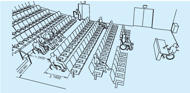
All dimensions in millimetres.
FIG. 92 EXAMPLES OF VIEWING SPACES FOR WHEELCHAIR USERS
B-14 Viewing Spaces in Assembly Areas
The floor area for a wheelchair viewing space shall be connected to an accessible path of travel and shall meet the following requirements (see Fig. 92):
a) It shall be at least 900 mm × 1400 mm ;
b) The depth of the row shall be minimum 2 400 mm;
c) It shall have clear and level surface;
d) It shall have sufficient manoeuvring space;
e) Spaces for several wheelchair users shall be provided. They shall be located beside regular seating rows, for the wheelchair user to be able to stay by his/her accompanying person, if relevant; and
f) It is recommended that the armrest on the seats at the end of the row (aisle seats) lift up to allow wheelchair users to transfer from the wheelchair onto a seat.
Some seats should be provided with foldable armrests, considering transferences (see B-12.3); some other seats should be wider, considering larger size people.
Wheelchair user viewing spaces shall provide viewing spaces that are,
a) comparable to those for all viewing positions with a minimum unobstructed eye level up to 1 200 mm; and
b) not reduced or obstructed by standing members of the audience.
Row and seat number identification signs shall be legible to persons who are visually impaired (see B-24).
In restaurants a minimum of 25 percent of the tables shall be usable by wheelchair users according to B-8.3. In bars, a minimum of 25 percent of bar counters shall not be more than 800 mm height, and shall have an unobstructed lateral access for wheelchair users.
Sufficient manoeuvring space between tables and the route to the accessible toilet facilities shall be provided.
The general design requirements for colour and visual contrast should also be considered, as described in B-24.3.
In self service restaurants, tray slides and counters shall be mounted at 800 mm from the floor for wheelchair users. Food shelves shall be mounted at a maximum height of 1 200 mm and aisle space of minimum 900 mm shall be provided. Where stools and high tables are provided, low tables suitable for wheelchair users shall be provided. Cantilevered table or tables with straight legs at each corner are preferable to central pedestals that might restrict wheelchair access.
Terraces, Verandahs and balconies shall be accessible to all people, including people with mobility impairments.
Parts of these facilities should be covered with a canopy, to give shelter against the weather (sun/rain/snow).
Walking surfaces shall be slip resistant.
The access to accessible bedrooms in non-domestic buildings (that is hotels, guesthouses, etc) shall comply with the requirements outlined in this annex and in particular with B-4 and B-5. The minimum number of accessible bedrooms in non-domestic buildings shall be in accordance with Table 8.
Rooms accessible for wheelchair users shall be designed for two beds. If a single bedroom accessible
for wheelchair users is provided, a queen size bed is preferred, 1 500 mm width × 2 000 mm length.
Free space on at least one of the long sides of the bed shall be provided. This space should be 1 500 mm, and shall not be less than 1 200 mm. At the foot of the bed, at least 1 200 mm is required (see Fig. 93 and Fig. 94).
Sufficient clear manoeuvring space is needed to gain access to facilities, including the shower.
There should be a bench for luggage at a height between 450 mm and 650 mm.
The minimum height of a bed shall be between 450 mm and 500 mm, when it is compressed under a 90 kg weight.
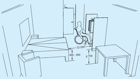
All dimensions in millimetres.
FIG. 93 EXAMPLE OF SPACE ALLOWANCES FOR ACCESSIBLE BEDROOM
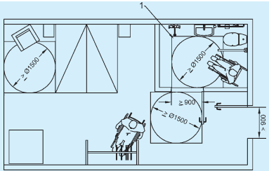
All dimensions in millimetres.
FIG. 94 EXAMPLE OF SPACE ALLOWANCES FOR ACCESSIBLE BEDROOM AND TOILET/SANITARY ROOM
For communication for people with hearing, vision and cognitive limitations, see B-21.
Visual and audible alarm systems shall be accessible to warn people with visual and hearing impairments.
Figures 87 and 88 shall be considered for accessible shower with an accessible toilet.
Kitchen areas shall take into account general design considerations in respect of manoeuvring space, slip resistant walking surface and accessible height of controls and devices. Wheelchair turning radius of at least 1 500 mm should be provided between the counter and the opposite walls. Floor surface should allow for easy wheelchair manoeuvrability. Essential kitchen appliances (oven, refrigerator, etc) should be usable
by persons both standing and sitting in a wheelchair, and a worktop should be located beside all appliances.
The sink taps should be reachable and easy to operate with one hand. The sink should be reachable for a wheelchair user. If a knee recess is provided under a sink, its underside should be insulated. Counter tops should be between 750 mm and 800 mm in height and provide for clear knee space for a wheelchair user. The clear knee space for a wheelchair user is at least 900 mm wide, 480 mm deep and 680 to 700 mm high (see Fig. 95 and Fig. 96). Counter tops/slabs should have rounded edge. All surfaces should be smooth to facilitate sliding of heavy items from one area to another. Slide-out working spaces are useful in providing an over-the lap working surface. For people with ambulatory disabilities, stools (preferably with
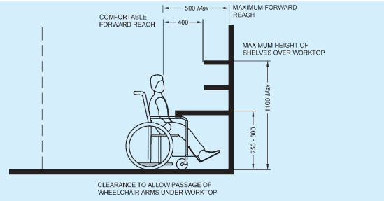
All dimensions in millimetres.
FIG. 95 REQUIREMENTS FOR COUNTER TOP
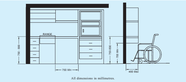
FIG. 96 KITCHEN SHELVES AND CABINETS
back and foot rests) should be provided strategically at the main work area.
A section of the shelves should be within reaching distance for a wheelchair user, between 300 mm and 1 100 mm above floor surface.
All controls and operating mechanisms should comply with B-7.
The minimum manoeuvring space and reachability for wheelchair users should be taken into consideration when designing and constructing a storage area. Part of the shelves should be within reaching distance for a wheelchair user, between 300 mm and 1 100 mm above the floor. If a door is provided, it should open outwards.
B-20 Accessible Housing
The site planning and development, approach to the building and access at entrance and within the building shall be in accordance with B-2, B-4 and B-5.
B-20.2 Interior
Sufficient manoeuvring space should be made available (at least 1 500 mm turning radius) for wheelchair user or person ambulating with an assistive device such as a walking frame or a white cane. Clear passage should be allowed from one room to the other. Unrestricted access should be provided to electrical outlets, telephones and wall switches. All controls and operating mechanisms shall comply with B-7 and a clear floor space for the wheelchair, of at least 900 mm × 1 200 mm should be provided in front of all the utilities and furniture.
Floor surface shall comply with B-5.2.7.
Doors and windows shall comply with B-5.3 and B-5.4, respectively.
B-20.2.4 Vertical circulation within the house shall be in accordance with B-6.
The bedroom should be planned to provide a 1 500 mm turning in space for wheelchair, at least near all the doors. There should be a clear floor space of at least 900 mm × 1 200 mm in front of all furniture.
The minimum height of a bed shall be between 450 mm
and 500 mm, when it is compressed under a 90 kg weight. Stability may be improved by placing the bed against a wall or in corner of the room (except for when the wheelchair user plans to make the bed). The bed should be so positioned so as to provide free space on at least one of the long sides of the bed. This space should be 1 500 mm, and shall not be less than 1 200 mm. At the foot of the bed, at least 1 200 mm is required (see Fig. 97).
A bedside table or cabinet between 450 mm and 900 mm from the floor may be useful to hold a lamp, telephone, necessary medications and a call bell if assistance is needed.
Wall hook installed at a height of 1100mm to 1300mm may be a useful addition to the closet area.
The closet should have a clear floor space of at
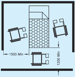
All dimensions in millimetres.
FIG. 97 SPACE AROUND BED
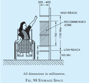
least 900 mm × 1 200 mm. It should have the clothes bar at a height of 1 200 mm from the floor. The shelves should be installed at various levels between 300 mm and 1 100 mm from the floor surface (see Fig. 98). The door handle should be conforming to B-7.
At least 1 500 mm turning in space for wheelchair should be provided near all entry points to the living room. A living-dining combination is preferable to a kitchen-dining combination (except when the wheelchair user does the cooking).
The seating space for a wheelchair user at the dining table should provide a clear knee space. The clear knee space for a wheelchair user is at least 900 mm wide, 480 mm deep and 680 to 700 mm high.
Floor surface should comply with B-5.2.7.
There should be a clear floor space for the wheelchair of at least 900 mm × 1 200 mm in front of all the fixtures. Chair seat heights should not be less than 500 mm.
Controls and operating mechanisms should comply with B-7.
Toilet or sanitary room shall comply with B-9.
Kitchen shall comply with B-18.
B-21 Acoustic Environment
The acoustic environment in a building should be suitable for its intended function for all building users. This includes all hearing people especially the hard of hearing. For deaf and hard of hearing people, good lighting is essential to understand the sign language interpreter and/or optical information devices. Many people with some degree of hearing loss have assistive devices to amplify sound, such as hearing aids or cochlear implants.
However, if the acoustic environment is not supportive of these devices, they do not work effectively. In addition, many people who have a mild or temporary hearing loss and do not have assistive devices may not be able to access information or communicate effectively. Most people with hearing loss and people without hearing loss rely on sight to lip read or interpret facial expressions; therefore where the acoustic environment is regarded as important, suitable lighting, colour and visual contrast should be considered to benefit all building users.
Information normally conveyed in visual form may not be accessible to people who are blind or partially sighted. This information should also be conveyed audibly; the clarity (speech transmission index) of this information is affected by the acoustic environment.
The following design considerations should be taken into account to maximize the functionality of the acoustic environment, and to support the use of assistive devices.
People with hearing impairments have particular difficulty in making out sounds and words in noisy environments. Adequate sound insulation should minimize noise from both outside and inside the building. Noise can often be mitigated, for example by introducing a buffer zone between a meeting area and extraneous noise, or partitioning a restaurant. The acoustics in a room are essentially connected with its location in the building and with the acoustic insulation of the building elements. The distribution of noise within the room itself and from exterior sources depends on the sound absorption of the surrounding surfaces and furnishing of the room. The calculation of acoustic absorption is significant in rooms where acoustic quality is important and also where noise reduction is required.
Good acoustics shall be achieved by optimizing the reverberation time, by considering the use/purpose of the room and by ensuring a low background noise level. The optimum reverberation time of a room should be determined having regard to the volume and the intended purpose of the room.
The geometry and shape of the room, as well as the distribution of sound absorbing and reflecting surfaces, are important. Surfaces that absorb sound should be carefully selected, as well as surfaces that reflect it. To develop an effective acoustic environment, sound absorbent surfaces can be used on floors and ceilings.
The optimum reverberation times for communication, speech only or music performance are different and depend on the size and shape of the room. Requirements for reverberation time shall be as per Part 8 ‘Building Services’, Section 4 ‘Acoustics, Sound Insulation and Noise Control’ of the Code.
A hearing enhancement system fitted at an information point can significantly assist communication for a person with a hearing impairment who uses a personal hearing aid, or has a cochlear implant. Hearing aids or cochlear implants may have a Telecoil (T-switch) which
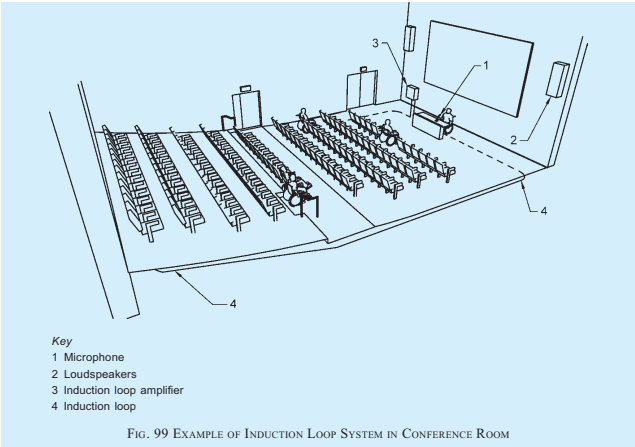
Key 1 Microphone 2 Loudspeakers 3 Induction loop amplifier 4 Induction loop
allows the listener to receive the sound signal directly.
NOTE — Hearing enhancement systems amplify audible communication and can be helpful to people who have a hearing impairment. They include a direct wire system, an inductive loop system, an infrared system, or a radio frequency system. All of these systems transmit a signal. Special purpose receivers are required for infrared and radio frequency systems, while hearing aids equipped with a T-switch are capable of receiving the signal from an induction loop system. Receivers can be equipped to be compatible with hearing aids.
Hearing enhancement systems, for example induction loops and infrared signal transmitting systems, shall be provided in conference and meeting areas. All seats, including the front scene, should be covered by hearing enhancement systems like induction loops (see Fig. 99). Portable hearing enhancement systems may be an alternative.
B-22 Lighting
The planning of artificial lighting should be co-ordinated with the planning of natural lighting, the choice of surfaces and colours. Lighting can be used to accentuate interior colour, tone and texture schemes, and to facilitate orientation. The lighting should not lead to glare or excessive contrast.
The routes to and around a building shall have sufficient
artificial lighting to facilitate awareness of changes of level or gradient. The positioning of lights should not cause glare, reflection or shadows. Ramps, entrances, steps, signage, etc, to the building should be well lit artificially, with an illuminance of at least 100 lux.
It should be possible to shade windows from bright light.
Lighting should provide visual conditions consistent with the visual task, orientation and safety. Key factors are,
a) level of illumination of horizontal and vertical surfaces;
b) limitation of glare from a light source or reflections;
c) uniformity and luminance distribution;
d) direction of lighting and shading; and
e) colour rendering.
NOTE — Good artificial lighting where needed is crucial for everyone, ensuring that vision impaired people are able to use buildings safely and conveniently, and that people with hearing impairments are able to lip read.
Lighting should facilitate wayfinding. Building elements should be marked by increased illumination.
The lighting in critical locations such as entrances, corridors, stairs, changes of level and workstations should facilitate their identification.
Time dependent switch devices shall have a progressive switch off to reach the next switch. An automatic switch on detection system shall cover the complete surface of ramps and stairs. Lighting shall provide sufficient time necessary for users to travel safely along ramps.
Lighting which switches off when people are still on ramps or stairs should be avoided.
NOTE — Ramps and stairs are the most hazardous places for falls.
All lighting, including natural light, should be controllable to avoid glare. Artificial lighting may be adjustable to suit individual needs.
Good light levels should be provided in hazardous areas such as stairs or changes in levels along a route, around doors and at communication or information systems. A minimum light level should be provided according to the visual task as given in different clauses of this annex.
Lighting conditions that support lip reading and sign language should be provided. The environment should be designed to avoid reflection and glare, and it should be possible to adjust both natural and artificial light.
Lighting should not produce glare. Glare and shadows may be avoided by,
a) shielding or shading light sources;
b) use of indirect lighting;
c) appropriate location of light source in relation to the direction of vision and to the object that is to be observed;
d) up lighters, with light sources at floor or low level, should not be used;
e) avoidance of windows at the end of corridors;
f) avoidance of light sources against dark surfaces by choosing light colours for ceilings or walls; and
g) avoidance of abrupt transitions from light to dark spaces. Indoor and outdoor lighting around the doorway should be suitably adjusted to prevent dazzle when entering or leaving the building.
NOTE — Due to the increase of optical scatter in the eye, the effects of glare are exacerbated for elderly people and for
individuals with some types of vision impairments (for example cataracts, corneal edema, and vitreous opacities). Glare can cause discomfort and interfere with task performance by decreasing the perceived contrast in visual displays (that is disability glare).
The provisions given in Part 8 ‘Building services, Section 1 Lighting and Natural Ventilation’ of the Code in respect of glare shall also be complied with.
Means of egress, alarm panel, alerting systems, evacuation plans, emergency evacuation routes, provision of area of rescue assistance/refuge areas and signages in such areas shall be in accordance with Part 4 'Fire and Life Safety' of the Code.
B-24 Orientation and Information, Signage, Graphical Symbols and Visual Contrast
B-24.1 Orientation and Information
The built environment should be designed, constructed and managed to facilitate orientation. Orientation means to find one's way, to avoid obstacles which could cause hazards, and to know when one has reached the destination.
Suitable provision shall be made at the entrance to the building and at decision points within the building to describe the location and nature of the building. In very complex buildings, visual, audible and tactile information should be provided.
Means to achieving satisfactory orientation conditions are,
a) planning layouts;
b) wayfinding and guided paths with TGSI (as given in this annex), other physical support of information (see B-24.3);
c) signage and symbols (see B-24.2);
d) visual contrast (see B-24.3);
e) choice of colours (see B-24.3.2);
f) avoiding surfaces which might make orientation more difficult;
g) lighting (see B-22); and
h) visual, audible and tactile information according to the two-sense principle (see B-24.1.2).
Orientation should be facilitated by differences in acoustics, material, light and colour. The design should indicate the use of the building elements.
To facilitate people with vision impairments who have
some residual vision, routes to be followed should have a difference in luminance to the surroundings (see B-24.3).
Additional illumination or visual contrast and tactile information, such as a change in material or tactile walking surface indicators, should be provided at decision points such as entrances, staircases, lifts, etc, to assist orientation and wayfinding.
Tactile ground surface indicators should be used to indicate directional orientation information where no other clues indicate the path of travel. Across large areas, halls and complex buildings, blind people need a tactile route or guiding pattern to follow (see B-2.5).
In complex buildings, an audible beacon should be installed in addition to visual and tactile information to provide information on decision points.
Supportive measures for information and wayfinding shall be provided in a format that is accessible to people with sensory impairments according to the principle of two senses, as given below (see also B-6.4.7):
a) audible/tactile information for people with vision impairments, and
b) visual information for people with hearing impairments.
Consideration should be given to provide suitable amplification and acoustic conditions; the message should be easily understandable and unambiguous. See also the principle of two senses in B-24.1.2.
Public address systems should be clearly audible and equipped with a hearing enhancement system as described as given in B-21.
Emergency information and warning systems are described in B-6.4.8, B-9.12 and B-9.13.
Information should be clear, concise, accurate and timely. Clarity of information can be defined as information that is legible and easily understood. Clarity of information therefore presupposes that people are able to distinguish between the different types of information that they receive.
Information can be divided into three levels,
a) Level 1 — Safety information;
b) Level 2 — General information; and
c) Level 3 — Advertising information.
It is important that these three levels of information be
clearly distinguished.
Information should be complete but concise. Too much information is difficult for people to retain.
All information provided should be accurate and consistent.
NOTE — Universally accepted pictograms should be used in preference to text.
B-24.2 Signage and Graphical Symbols
Signs should be readable and legible for people who have vision or mental impairments. Well-illuminated, clear and readable signs shall be placed at a consistent height (see B-24.2.4).
Information with text should be supplemented with graphical symbols to facilitate comprehension for everyone (see B-24.2.16 for graphical symbols).
Signs should be provided in relief and Braille (see B-24.2.10).
The signs should be made of robust materials and be easy to change, clean and repair. Some suggested materials for signage are wood, acrylic and aluminium composite panel (ACP).
An excessive quantity of signs in close proximity should be avoided, as well as visual material placed too close to wall fixed signs (for example posters, timetables, etc).
Where Braille is used as a complementary or independent feature to tactile signs it should be easy to locate.
The main types of signs are:
a) Orientation signs — Sketches, plans, models, etc.
b) Directional signs — Directional information from point A to B.
c) Functional signs — Explanatory information.
d) Informative signs — Purely informative, for example a name.
e) Signs for emergency exits (see Part 4 ‘Fire and Life safety’ of the Code).
B-24.2.3 Placement of Signs
Informative signs shall be located adjacent to the entrance door and be illuminated and clearly visible. The sign shall be placed on the latch side. Design and size of letters shall be in accordance with B-24.2.5.
Communication systems shall also be placed on the latch side and preferably in a range of 1 000 mm to 1 200 mm above ground level.
Orientation signs should be located in accessible places adjacent to, but not directly in, main access routes so that they can be examined without disturbance.
In public buildings there should be an orientation plan immediately inside the main entrance. This plan should follow all relevant design criteria stated in this Part and in B-24.3.
Directional signs should clearly direct people to the facilities. They should be located where directional decisions are made and constitute a logical orientation sequence from the starting point to different points of destination. They should be repeated, not too often, but every time there is a possibility of alteration in the traffic direction.
Directional signage to washrooms should be provided in all parts of a precinct or building.
Stairwells should have information signs identifying all points of entry and exit.
Floor numbers shall be located on each floor at top and bottom of stairs, on handrails and on each side of the outer frame of each lift-car entrance on each floor and prominently displayed elsewhere so they are visible from the lift car at each level.
Directional and functional signs should be located below 1600mm where they are easy to approach, to
touch and read the raised signs with the fingers (see B-24.2.10 to B-24.2.12).
Signs should be located where they are clearly visible to people who are seated, standing or walking.
Signs should be placed between 1 200 mm and 1 600 mm from the floor or ground surface. It should be possible to approach the sign to be read from a short distance (see Fig. 100).
Where it is likely that the sign may be obstructed, as in a crowded situation, the signs shall be placed at a height of at least 2 100 mm above the floor. The same requirement applies to signs fixed to the ceiling or projecting from walls. In that case, there should be two signs; one that can be seen from a distance above other people's heads, one as a complement at the height recommended above.
Where there is sufficient space, door signs shall be located on the latch side of the door within 50 mm to 100 mm of the architrave (see Fig. 101).
The fonts should be easy to read. The font style should be a sans serif font similar to Helvetica or Arial medium.
The letter height depends on the reading distance. A letter height between 20mm and 30mm for each metre of viewing distance is preferred. The letter height should not be less than 15mm.
Usage of too many type sizes on any one sign should be avoided. Also italics, script texts, condensed texts, light stems should be avoided. Consistent font stem widths should be used.
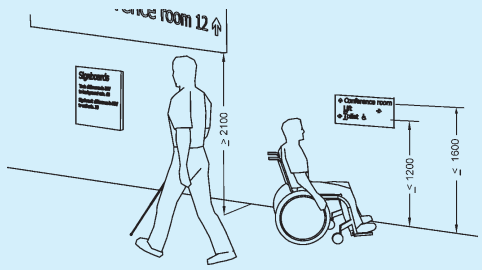
All dimensions in millimetres.
FIG. 100 HEIGHT OF SIGNS
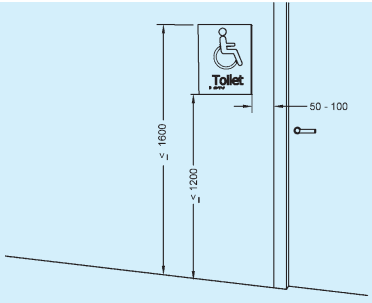
All dimensions in millimetres.
FIG. 101 LOCATION OF DOOR SIGNS ON THE LATCH SIDE OF THE DOOR
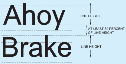
FIG. 102 LINE HEIGHT AND SPACING
CHARACTER PROPORATION
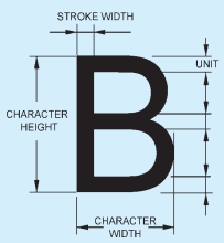
CHARACTER HEIGHT
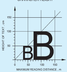
FIG. 103 DIMENSIONS OF CHARACTER IN A SIGNAGE SYSTEM
It is recommended that messages of single words or groups of words begin with an upper case letter and continue with lower case letters (sentence case).
The words should not be placed too close together. Adequate height spacing should separate the lines. Lines of text should be ranged from a vertical line (unjustified).
Signs with a single word may be centre justified, else the text should be left justified.
The spacing between two lines shall be 50 percent of the line height (see Fig. 102).
A style shall be chosen based on a character width-to-height ratio within 3:5 and 1:1 and the stroke width-to-height ratio between 1:5 and 1:10. It shall be consistent for each sign (see Fig. 103).
Minimum difference in LRV for small targets, such as signs and inscriptions, to signboards, should be 70 points. Signboards should have a minimum difference in LRV from the background of 30 points.
Red-green combination should be avoided. Difficulties in perception can also appear when using the colours green, olive green, yellow, orange, pink and red (see also B-24.3 for contrast).
Signs should be glare free when mounted. This depends on how the sign is placed, the material and the illumination. The background, graphical symbols, logos and other features shall be of a matte or low sheen finish.
Signs should be well illuminated with no glare with uniform lighting over the surface of the sign of between 100 and 300 lux. Minimum acceptable level of lighting for directional signage, maps and text panel is 200 lux. Signs can be luminescent or artificially lit.
Signs should be readily understandable. They should be designed so as to be simple and easy to interpret. The message should be unambiguous.
Short sentences and simple words should be used. Abbreviations and very long words are hard to understand and should be avoided.
Signs on panels in lifts, room numbers of rooms in hotels, doors to public toilets and so on shall be raised tactile and include Braille (see also B-24.2.4).
The preferred height of raised tactile information is between 1 200 mm and 1 600 mm. Signs with tactile information placed at a lower height should be mounted at an angle from the horizontal (preferably 20° to 30° , maximum 45° ).
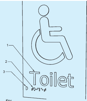
Key
1 Raised tactile letters and graphical symbols, height 15 mm to 55 mm, minimum relief 0.8 mm (1 mm to 1.5 mm relief is preferred)
2 Braille text
3 Braille Locator
FIG. 104 EXAMPLE OF RAISED TACTILE SIGNS AND BRAILLE
B-24.2.11 Tactile Letters, Figures, Signs and Graphical Symbols
The height of letters, figures, signs and graphical symbols shall be between 15 mm and 55 mm (see Fig. 104).
The minimum height of its relief shall be 0.8mm; a height between 1mm and 1.5mm is preferred (see Fig. 104).
The profile of the relief should be shaped as a rounded upside-down turned letter V.
Where an arrow is used in the tactile sign, a small arrow shall be provided for Braille readers.
On signs with multiple lines of text and characters, a semi-circular Braille locator on the left margin shall be horizontally aligned with the first line of Braille text.
Braille should be raised, domed and comfortable to touch. It should be located 8 mm below the bottom line of the text and be left justified.
Common alternative formats may be used to assist people with visual impairments who are best able to interpret information through hearing or touch. Embossed letters, raised pictograms and raised arrows are tactile features that may be incorporated into signs, which may be particularly helpful to persons with visual impairments.
Tactile symbols applied on handrails, doors, maps or floor plans shall have a raised relief contour similar to tactile letters.
Only essential information should be included on a tactile map or floor plan.
Tactile maps shall be angled between 20° and 30° from the horizontal for ease of reading, and the bottom edge shall be at a minimum height of 900 mm. The map should have a level of illumination between 350 lux and 450 lux, without glare.
The key should be located at the bottom of the map and left justified. The use of a recessed Braille locator on the left hand side should assist in locating the legend.
The map shall be orientated with the building.
If video and media information displays are used, they should be placed at a height according to B-24.2.4 and their lettering, etc, should be in conformity with the recommendations above.
Glare from artificial and natural lighting on the screen shall be avoided by,
a) positioning the display or the screen out of direct light; or
b) shading the display or the screen.
A complementary audible information system should be provided.
The international symbol of accessibility (see Fig. 105)
shall be replicated consistently in all wheelchair signage. The preferred colour is navy blue with white lettering.
105A PROPORTIONS
Graphical symbols should be used in conjunction with building signage system, wherever possible.
Graphical symbols shall be highly contrasted with a minimum difference in LRV of 70 points and properly illuminated. They shall be used on guides and directional signage (see also B-24.3).
Graphical symbols on directional and door signs should be tactile, and should be accompanied by raised lettering and Braille (see B-24.2.13). Signs above a height of 1 600 mm do not need to be tactile, nor to include raised lettering or Braille information.
The size of graphical symbols is dependent on the viewing distance (D). The minimum size of the inner outline of the frame of graphical symbols (s) can be derived from formula s = 0.09 D, applicable for a viewing distance of 1000mm to 10000mm.
The following accessible graphical symbols shall be used to denote particular components of a facility. The following facilities for disabled persons shall be marked as:
a) Those relating to people with mobility impairments,
car parking places (parking places, garages);
access and entrances without steps to buildings, especially where they are not identical with the main entrance;
accessible lifts, in cases where not all lifts are accessible; lifting platforms and similar mounting devices;

105B DISPLAY CONDITIONS
FIG. 105 INTERNATIONAL SYMBOL OF ACCESSIBILITY

NOTE — This graphical symbol also indicate full accessibility or accessible toilets.
FIG. 106 ACCESSIBLE FACILITY OR ENTRANCE
FIG. 107 SLOPED OR RAMPED ACCESS
FIG. 108 TOILETS ACCESSIBLE, FEMALE AND MALE

FIG. 109 TOILETS ACCESSIBLE, FEMALE
FIG. 110 TOILETS ACCESSIBLE, MALE
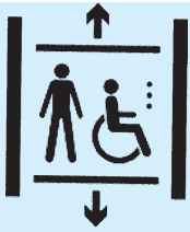
FIG. 111 ACCESSIBLE LIFT

FIG. 112 ACCESSIBILITY, BLIND OR LOW VISION

FIG. 113 ACCESSIBILITY, LIMITED WALKING CAPABILITY

FIG. 114 ACCESSIBILITY, ASSISTANCE DOG

FIG. 115 ACCESSIBILITY, HARD OF HEARING

FIG. 116 ACCESSIBILITY, PERSONAL ASSISTANT AVAILABLE

FIG. 117 ACCESSIBILITY, VISION IMPAIRED
accessible sanitary rooms;
wheelchair viewing spaces and accessible seating;
changing rooms; and
steps or hoists providing access to swimming pools.
b) Those relating to people with vision
impairments: locations where audible and tactile information is provided.
c) Those relating to people with hearing impairments,
telephones and emergency call facilities, equipped with sound amplification; and
provision of an assistive listening system. Some of the graphical symbols relevant to accessibility are shown in Figs. 106 to 118.
B-24.3 Visual Contrast
In order to facilitate orientation and to ensure safe use of an environment, adjacent surfaces, information and potential hazards shall provide a discernible visual contrast.
A minimum difference in LRV shall be provided in relation to the visual task in accordance with Table 11. Additionally, one of the two surfaces should have an LRV value of minimum 30 points for door furniture, 40 points for large area surfaces and 70 points for potential hazards and text information.
The minimum difference in the LRV shall be achieved and maintained throughout the life of the building elements. Deterioration and maintenance shall be considered at installation.
For lighting conditions lower than specified in this Code, the difference in LRVs should be higher.
NOTES
1 The LRV, sometimes also called the luminance reflectance value, or CIE Y value, is expressed on a scale of 0-100, with a value of 0 points for pure black and a value of 100 points for pure white.
2 The perception of visual contrast increases with better lighting conditions.
3 Reflections and glare from shiny surfaces can reduce visual contrast and can confuse people with vision impairments.

NOTE — Fig. 118 is a combination sign which combines a safety sign and one or more associated supplementary signs on the same rectangular carrier. The signs used in the figure are the following:
a) Running man (centre of the combination sign) — Emergency exit (right hand).
b) Arrow (right) — Supplementary arrow sign used with the emergency exit sign to indicate its location in the right direction.
c) Supplementary sign (opposite to the arrow) — Full accessibility or toilets accessible.
FIG. 118 ACCESSIBLE EMERGENCY EXIT ROUTE
| Sl No.(1) | Visual Task(2) | Difference on the LRV Scale(3) | Approximate Examples of Colour Contrasting(4) |
|---|---|---|---|
| i) | Large surface areas (that is, walls, floors, doors, ceiling), elements and components to facilitate orientation (that is, handrails, switches and controls, tactile walking surface indicators, and visual indicators on glazed areas) | ≥30 points | |
| ii) | Potential hazards and self contrasting markings (that is, visual indicator on steps) and text information (that is, signage) | ≥70 points |
For door hardware (that is, the elements and components to facilitate opening and closing doors) a difference in LRV between the product and its background of at least 15 points and a minimum light reflectance value of 30 points for one of the two surfaces is acceptable.
NOTE — Door hardware is normally positioned at the same height on a door and is either on the left or right side. This makes the location of door hardware easier than other features. In addition, the three-dimensional features of door hardware create shadows and bright spots, which further enhance their location.
Floor patterns should have a visual contrast of less than 20 points difference on the LRV scale.
NOTE — Highly contrasted floor patterns can be perceived as differences in floor level, which may confuse people with vision impairments or cognition capacity. Highly contrasted floor patterns may trigger an attack of vertigo.
Different colours should be used for identification of doors, different storeys or departments in a building to aid persons with impaired cognitive ability. The colours used to facilitate orientation shall also provide minimum difference in LRV according to B-24.3.1. Combinations of red tones and green tones should be avoided.
Different storeys should be marked with clearly defined large numbers relating to the floor (that is, ‘2’ for the second floor, and so on) both in the stairwells to assist those evacuating and at the lift and stair lobbies on each level.
NOTE — Colour coding floors may not be practical from a long term maintenance perspective.
In case of signage and graphical symbols, contrasting colours shall be used to differentiate the figures from the background on the signboard. The colours of signboard shall also contrast with the surrounding surface so as to be clearly distinguishable (see B-24.2.6). Information from signs may be conveyed by the colour and brightness differentials between the letter and the background. For graphical symbols, it is preferable to use blue and white colours. Colours same as safety signs shall be avoided in other signs. Primarily red, yellow or green colour is used for safety signs. The colour combinations red/ green and yellow/blue should not be used in order to avoid confusing persons who are colour blind. Use of the shades of the same colour in the sign and also use of more than 5 colours in a signage should be avoided.
A preferred schedule of colour contrast for signs from their background is given below:
| Sl No. | Background | Sign Board | Legend |
|---|---|---|---|
| (1) | (2) | (3) | (4) |
| i) | Red brick or dark stone | White | Black, dark green or dark blue |
| ii) | Light brick or light stone | Black/dark | White or yellow |
| iii) | Whitewashed walls | Black/dark | White/Yellow |
| iv) | Green vegetation | White | Black, dark green or dark blue |
| v) | Back-lit sign | Black | White or yellow |
B-25.1 Effective management of the built environment is essential to ensure that a building can be used by everyone. Management policies and procedures will be required to ensure that accessibility is maintained on an ongoing basis. The following management and maintenance issues, are important factors in ensuring that a building is easily accessed and used by disabled people.
a) Keeping external routes, including steps and ramps, clean, unobstructed and free of surface water, dead leaves, lichen, debris, etc;
b) In car parking areas: ensuring that designated spaces are not being used by non-disabled motorists;
c) Where possible, allocating specific designated parking spaces to individual employees, marked by name or number;
d) Checking side-hung doors accompanying revolving doors to ensure they are not kept locked; and
e) Making available auxiliary aids such as portable ramps, and removing them when not in use.
a) Ensuring that wheelchair spaces are available in seating areas;
b) Ensuring that staff understand the management issues relating to disabled people, including emergency procedures;
c) Ensuring that storage, planters, bins, etc, do not obstruct circulation space, WCs or lift call buttons;
d) Ensuring that cleaning and polishing does not
produce a slippery surface;
e) Ensuring that trip hazards, such as at junctions between floor surfaces, are removed;
f) Ensuring access between moveable tables in refreshment areas;
g) Ensuring that in sanitary facilities, written instructions on the use of equipment is displayed beside each item;
h) Ensuring in sanitary facilities, that information is available on the type of sling connector and the types of sling that are compatible with their installed hoist and track;
j) Ensuring that a procedure is set up to respond to alarm calls from sanitary accommodation;
k) Ensuring that waterproof mattress covers can be made available for use in accessible bedrooms in non-domestic buildings;
m) Ensuring that, where floor sockets are provided (for example in meeting rooms), access to sockets is also available at desk level;
n) Ensuring that any temporary barriers that are used to channel customers to reception or serving points, and whose configuration needs to be changed frequently, have a semi-rigid top barrier (for example a spring-loaded band) which contrasts visually with the background against which it is seen; and
p) Ensuring that assistance is made available to carry trays where needed in refreshment areas.
a) Maintaining doors, door closers and building hardware, including checking that the opening forces of self-closing doors are within acceptable limits;
b) Maintaining access control systems;
c) Checking floor surfaces, matting, surface-mounted carpets, etc, re-fixing to the floor where necessary, and replacing where damaged or worn (particularly at entrances to buildings);
d) Maintaining hearing enhancement systems;
e) Maintaining sanitary fittings, including checking that toilet seats are securely fixed, cleaning tap nozzles to ensure correct water flow, emptying and cleaning bins, and keeping equipment clean;
f) Ensuring that adjustable shower heads are lowered to be ready for the next user;
g) Ensuring that emergency assistance pull cords are kept fully extended and in working order at all times;
h) Checking the mountings of all grab bars, and the mechanism of drop-down bars, re-fixing or replacing, where necessary;
j) Servicing of all types of lifts and hoists;
k) Ensuring that facilities, such as lifts, hoists, etc, are in working order between servicing schedules, and providing alternative arrangements in case of facilities being out of order;
m) Maintaining ventilation and heating equipment;
n) Replacing defunct light bulbs and flickering fluorescent tubes quickly; and
p) Keeping windows, lamps and blinds clean to maximize lighting.
a) Providing information on strobe lighting prior to entry;
b) Removing and/or changing signage as necessary, for example when departments relocate;
c) Providing accurate information on facilities prior to arrival;
d) Providing audio description services;
e) Providing all relevant literature, and reviewing/revising it when necessary;
f) Ensuring that a permanently manned position is available for the emergency lift telephone communications;
g) Updating maps of buildings following changes; and
h) Replacing signs correctly after decoration.
a) Allocating and reviewing parking spaces;
b) Changing signs when departments move;
c) Reviewing the number of disabled people attending and needing facilities;
d) Establishing and running user groups;
e) Reviewing the number of instruments supporting infra-red systems;
f) Adopting a signage policy;
g) Having the loop position always manned in branches;
h) Providing portable ramps;
j) Arranging audits of journeys made by visitors;
k) Instructing accessibility audits;
m) Ensuring that services are provided when facilities such as lifts break down;
n) Ensuring that responsibilities are defined within the organization;
p) Ensuring that accessibility improvements are picked up whenever possible during maintenance and refurbishment work;
q) Reviewing and improving evacuation procedures;
r) Training of staff;
s) Reviewing all policies, procedures and practices;
t) Reviewing the provision of auxiliary aids; and
u) Considering the impact of background noise (for example music, equipment, ventilation) on people with a range of sensory conditions (hearing, vision, autism). This is especially important in areas where voice communication is necessary, such as reception, meeting and learning spaces.
| ix) Important information via two senses or more, for example visual, audible and tactile | ix) Important information via two senses or more, for example visual, audible and tactile |
| v) | Assembly buildings | Stadia, theatres, lecture halls, spectator seating in sports centres and all other type of assembly halls with fix seatings, by whatever name called | To all common areas/facilities open to public and staff. Number of designated seating areas to be as per B-12.3. |
| vi) | Public transit buildings | Bus terminus, airports, railway/metro stations, organized inter-change points/transit junctions, taxi stands | All public areas used by passengers and staff including but not limited to drop off areas, parking, boarding/transfer areas, waiting areas/lounges, custom areas, baggage halls, booking halls, inquiry offices, ticket counters, shops, banks, etc. |
| vii) | Heritage buildings/sites | All heritage sites/buildings protected by concerned authorities and open to public, interpretation centres, ancillary services/ facilities | a) Reasonable access to all public areas without affecting the historical character of the building.b) Alternative solutions and innovative methods that do not conflict with conservation/preservation requirements should be explored. |
| Table 8 — (Concluded) | Table 8 — (Concluded) | Table 8 — (Concluded) | Table 8 — (Concluded) |
| (1) | (2) | (3) | (4) |
| viii) | Public toilets | To be provided in accordance with B-9.15. |
| ix) | Cafeterias and restaurants | To be provided in accordance with B-15. |
| x) | Sports buildings | a) Sports halls, administration and common areas.b) At least one changing room and shower room to be provided at every place where such facility is provided.c) Spectators seating areas for wheelchair users as per assembly buildings above. |
| xi) | Mercantile buildings | Shops, malls, large multi-storey department stores and super markets, etc | At least one trial room for each group of such facility. Where only one is provided, it shall be accessible. |