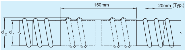
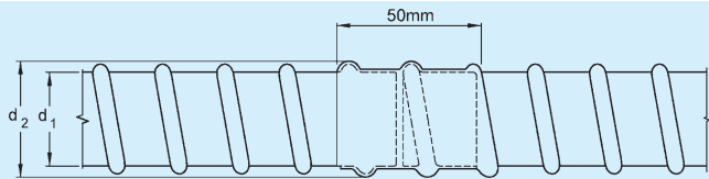
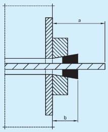
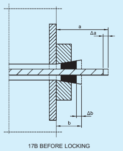
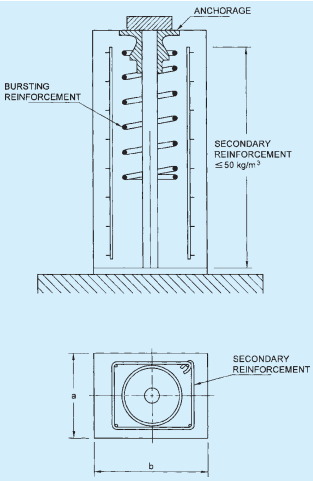
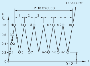
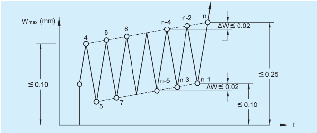
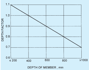
Provisions on modulus of elasticity have been modified.
Grades of concrete have been specified up to M 80 from the existing M 30 to M 60.
Provisions on creep and shrinkage of concrete have been revised.
Durability requirements have been covered exhaustively in line with IS 456 as applicable to prestressed concrete; the maximum cement content has been specified as 450kg / m³.
Assumed standard deviation has been specified as 5.0N / mm² for concrete mix proportioning.
Provisions on assembly of prestressing and reinforcing steel and on prestressing have been thoroughly revised in line with the present improved practices, and details on protection of prestressing steel, sheathing and anchorages have been incorporated.
Sampling and strength test of designed concrete mix has been modified in line with IS 456.
d) The Sections on General Design Requirement and Structural Design (Limit State) have been modified as follows:
Provisions are in line with IS 456 as applicable.
Design provisions are updated in line with the latest practices.
e) Provisions related to bearing stress in the end zone in post-tensioned members have been updated.
f) Provisions related to ultimate shear resistance of a section uncracked in flexure have been updated.
g) Provisions related to ultimate shear resistance of a section cracked in flexure have been updated.
h) Test on wall thickness of the duct of corrugated HDPE sheathing duct has been updated.
In this Code, it has been assumed that the design of prestressed concrete structures is entrusted to a qualified engineer, and that the execution of the work is carried out under the direction of an experienced supervisor.
All standards, whether given herein above or cross-referred to in the main text of this Subsection, are subject to revision. The parties to agreement based on this Subsection are encouraged to investigate the possibility of applying the most recent editions of the standards.
For the purpose of deciding whether a particular requirement of this Subsection is complied with, the final value, observed or calculated, expressing the result of a test or analysis, shall be rounded off in accordance with IS 2 : 1960 ‘Rules for rounding off numerical values (revised)’. The number of significant places retained in the rounded off value should be the same as that of the specified value in this Subsection.
SECTION 5B (A) GENERAL
1Scope
1.1 This Code (Part 6/Subsection 5B) deals with the general structural use of prestressed concrete. It covers both work carried out on site and the manufacture of precast prestressed concrete units.
1.2 Special requirements of structures such as pipes and poles covered in respective standards have not been covered in this Subsection; these standards shall be used in conjunction with this Subsection. This Subsection does not cover specific provisions regarding bridges.
2Terminology
For the purpose of this Subsection, the following definitions shall apply, and for other terms those given in the accepted standard [6-5B(1)] shall apply.
2.1 Anchorage Device — In post-tensioning, the hardware used for transferring the post-tensioning force from the tendon to the concrete in anchorage zone.
2.2 Bonded Member — A prestressed concrete member in which tendons are bonded to the concrete either directly or through grouting.
2.3 Bonded Post-Tensioning — Post-tensioned construction in which the annular spaces around the tendons are grouted after stressing, thereby bonding the tendon to the concrete section.
2.4 Cable — A group of wires or bars or strands or rods.
2.5 Characteristic Load — Load which has 95 percent probability of not being exceeded during the life of the structure (see 20.2).
2.6 Characteristic Strength — Strength of material below which not more than 5 percent of the test results are expected to fall (see 20.1).
2.7 Column or Strut — A compression member, the effective length of which exceeds three times the least lateral dimension.
2.8 Creep — Time dependent deformation due to sustained load.
2.9 Creep Coefficient — The ratio of creep strain to elastic strain in concrete.
2.10 Final Prestress — The stress which exists after substantially all losses have occurred.
2.11 Final Tension — The tension in the prestressing tendon corresponding to the state of the final prestress.
2.12 Initial Prestress — The prestressing force in the tendon at transfer.
2.13 Initial Tension — The maximum stress induced in the prestressing tendon at the time of the stressing operation.
2.14 Post-Tensioning — A method of prestressing concrete in which prestressing steel is tensioned against the hardened concrete.
2.15 Prestressed Concrete — Concrete in which permanent internal stresses are deliberately introduced, usually by tensioned steel, to counteract to the desired degree the stresses caused in the member during service.
2.16 Pre-Tensioning — A method of prestressing concrete in which the tendons are tensioned before concreting.
2.17 Relaxation — Time dependent decrease in steel stress at constant strain.
2.18 Sheathing — A material encasing a prestressing tendon to prevent bonding the tendon with the surrounding concrete during placement of concrete and to provide protection against corrosion.
2.19 Short Column — A column, the effective length of which does not exceed 12 times the least lateral dimension.
2.20 Slender Column — A column, the effective length of which exceeds 12 times the least lateral dimension.
2.21 Shrinkage Loss — The loss of stress in the prestressing steel resulting from the shrinkage of the concrete.
2.22 Stress at Transfer — The stress in both the prestressing tendon and the concrete when the prestressing tendon is released from the prestressing mechanism.
2.23 Tendon — A steel element, such as a wire, cable, bar, rod or strand, or a bundle of such elements used to impart prestress to concrete when the element is tensioned.
2.24 Transfer — The act of transferring the stress in prestressing tendons from the jacks or pre-tensioning bed to the concrete member.
2.25 Transmission Length — The distance required at the end of a pre-tensioned tendon for developing the maximum tendon stress by bond.
3Symbols
For the purpose of this Subsection, the following letter symbols shall have the meaning indicated against each; where other symbols are used, they are explained at the appropriate place:
A = Area
B = Breadth of beam
bw = Breadth of web or rib
D = Overall depth of beam
DL = Dead load
d = Effective depth of beam
dt = Effective depth of beam in shear
Ec = Short term modulus of elasticity of concrete
EL = Earthquake load
Es = Modulus of elasticity of steel
e = Eccentricity
F = Characteristic load
Fbst = Bursting tensile force
Fd = Design load
f = Characteristic strength of material
fci = Cube strength of concrete at transfer
fck = Characteristic compressive strength of concrete
fcp = Compressive stress at centroidal axis due to prestress or average intensity of effective prestress in concrete
fcr = Modulus of rupture of concrete (flexural tensile strength)
fd = Design strength
fp = Characteristic strength of prestressing steel
fpe = Maximum prestress after losses
fpi = Maximum initial prestress
fpu = Ultimate tensile stress in the tendons
ft = Maximum principal tensile stress
fy = Characteristic strength of reinforcement
IL = Imposed load
M = Bending moment
m = Modular ratio
P = Load due to prestressing effect
s = Spacing of stirrups
T = Torsional moment
V = Shear force
Vc = Ultimate shear resistance of concrete
Vco = Ultimate shear resistance of a section uncracked in flexure
Vcr = Ultimate shear resistance of a section cracked in flexure
WL = Wind load
xu = Depth of neutral axis
γf = Partial safety factor for load
γm = Partial safety factor for material
δm = Percentage reduction in moment
τc = Shear stress in concrete
φ = Diameter of tendon or bar
Section 5B (B) Materials, Workmanship, Inspection and Testing
7Durability of Concrete
7.1 General
A durable concrete is one that meets predetermined expectations under the working environment (exposure) conditions during its service life. The materials and mix proportions specified and used should be such as to maintain its integrity and, if applicable, to protect embedded metal from corrosion.
7.1.1 One of the main characteristics influencing the durability of concrete is its permeability to the ingress of water, oxygen, carbon dioxide, chloride, sulphate and other potentially deleterious substances. Impermeability is governed by the constituents and workmanship used in making the concrete. With normal-weight aggregates a suitably low permeability is achieved by having an adequate cement content, sufficiently low free water/cement ratio, by ensuring complete compaction of the concrete, and by adequate curing.
The factors influencing durability include,
a) the environment;
b) the cover to embedded steel;
c) the type and quality of constituent materials;
d) the cement content and water-cement ratio of the concrete;
e) workmanship, to obtain full compaction and efficient curing; and
f) the shape and size of the member.
The degree of exposure anticipated for the concrete during its service life together with other relevant factors relating to mix composition, workmanship, design and detailing should be considered. The concrete mix to provide adequate durability under these conditions should be chosen taking account of the accuracy of current testing regimes for control and compliance as described in this Subsection.
4Materials
4.1 Cement
The cement used shall be any of the following conforming to accepted standards [6-5B(2)] and the type selected should be appropriate for the intended use:
Other combinations of Portland cement with mineral admixtures (see 4.2) of quality conforming to relevant Indian Standards laid down may also be used in the manufacture of concrete provided that there are satisfactory data on their suitability, such as performance test on concrete containing them. Rate of slow gain of strength with Portland slag cement and Portland pozzolana cement should be taken into account while deciding the de-shuttering time, curing period and the time of prestressing (see also 10 and 13).
4.1.1 Low heat Portland cement conforming to the accepted standard [6-5B(3)] shall be used with adequate precautions with regard to removal of formwork, etc.
4.1.2 High alumina cement conforming to the accepted standard [6-5B(4)] or supersulphated cement conforming to the accepted standard [6-5B(5)] may be used only under special circumstances with the prior approval of the engineer-in-charge. Specialist literature may be consulted for guidance regarding the use of these types of cements.
4.1.3 The attention of the engineer-in-charge and users of cement is drawn to the fact that quality of various cements mentioned in 4.1 is to be determined on the basis of its conformity to the performance characteristics given in the respective Indian Standard specification for that cement. Any trade-mark or any trade name indicating any special features not covered in the standard or any qualification or other special performance characteristics sometimes claimed/indicated on the bags or containers or in advertisement alongside the ‘Statutory Quality Marking’ or otherwise have no relation whatsoever with the characteristic guaranteed by the ‘Statutory Quality Marking’ as relevant to that cement. Consumers are, therefore, advised to go by the characteristics as given in the corresponding Indian Standard specification or seek specialist advice to avoid any problem in concrete making and construction.
4.2 Mineral Admixtures
Mineral admixtures used shall conform to 4.2 of Part 6 'Structural Design, Section 5 Concrete, Subsection 5A Plain and Reinforced Concrete' of the Code. When mineral admixtures are used, rate of slow gain in strength should be taken into account while deciding the de-shuttering time, curing period and the time of prestressing (see also 10 and 13).
4.3 Aggregates
All aggregate shall comply with the requirements of accepted standard [6-5B(6)].
4.3.1 Heavy weight aggregates may also be used provided the engineer-in-charge is satisfied with the data on the properties of concrete made with them.
NOTE — Some of the provisions of the standard would require modification when these aggregates are used. Specialist literature may be consulted for guidance.
4.3.2 Size of Aggregates
The nominal maximum size of coarse aggregate should be as large as possible within the limits specified but in no case greater than one-fourth of the minimum thickness of the member, provided that the concrete can be placed without difficulty so as to surround all prestressing tendons and reinforcements thoroughly and fill the corners of the form. For most work, 20 mm aggregate is suitable.
The nominal maximum size of the aggregate shall be 5mm less than the spacing between the tendons, sheathings, ducts or untensioned steel, where provided.
4.4 Water
The requirements of water used for mixing and curing shall conform to the requirements given in 4.4 of
Part 6 ‘Structural Design, Section 5 Concrete, Subsection 5A Plain and Reinforced Concrete’ of the Code. However, use of sea water is prohibited.
4.5 Chemical Admixtures
Chemical admixtures shall be used according to 4.5 of Part 6 ‘Structural Design, Section 5 Concrete, Subsection 5A Plain and Reinforced Concrete’ of the Code.
4.6 Prestressed and Untensioned Steel
4.6.1 Prestressing Steel
4.6.1.1 The prestressing steel shall be any one of the following conforming to accepted standards [6-5B(7)]:
a) Plain hard-drawn steel wire (cold-drawn stress relieved wire),
4.6.1.1.1 All prestressing steel shall be free from welded joints and splits, harmful scratches, surface flaws; rough, jagged and imperfect edges and other defects likely to impair its use in prestressed concrete.
4.6.1.2 Mechanical properties
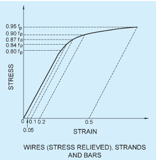
Data in respect of modulus of elasticity, relaxation loss at 1 000 h at mean temperature of 20° C, minimum ultimate tensile strength, stress-strain curve, etc, shall necessarily be obtained from manufacturer. Prestressing steel shall be subjected to acceptance tests prior to actual use on the works. The modulus of elasticity value, as per acceptance tests, shall conform to the values assumed in the design which shall be within a range not more than 2.5 percent between the maximum and the minimum.
4.6.1.2.1 For design purposes, the minimum requirements given in the relevant Indian Standards may be adopted.
4.6.2 Untensioned Steel
4.6.2.1 The reinforcement used as untensioned steel shall be any of the following conforming to accepted standards [6-5B(8)]:
a) Mild steel and medium tensile steel bars.
b) High strength deformed steel bars.
c) Hard-drawn steel wire fabric.
4.6.2.2 All reinforcement shall be free from loose mill scales, loose rust and coats of paints, oil mud or any other substances which may destroy or reduce bond. Sand blasting or other treatment is recommended to clean reinforcement.
Special precautions like coating of reinforcement may be required for reinforced concrete elements in exceptional cases and for rehabilitation of structures. Specialist literature may be referred to in such cases. Reduction in design bond strength of coated bars shall be looked into.
4.6.2.3 The modulus of elasticity of steel shall be taken as 200 kN/mm² . The characteristic yield strength of different steel shall be assumed as the minimum yield stress/0.2 percent proof stress specified in the relevant Indian Standard.
4.7 Storage of Materials
Storage of materials shall be as described in good practice [6-5B(9)].
8Concrete MIX Proportioning
8.1 Mix Proportion
The mix proportions shall be selected to ensure the workability of the fresh concrete and when concrete is hardened, it shall have the required strength, durability and surface finish.
8.1.1 The determination of the proportions of cement, aggregates and water to attain the required strengths shall be made by designing the concrete mix; such concrete shall be called ‘Design mix concrete’.
8.1.2 Information Required
In specifying a particular grade of concrete, the following information shall be included:
h) Maximum temperature of concrete at the time of placing,
j) Method of placing, and
k) Degree of supervision.
8.1.2.1 In appropriate circumstances, the following additional information may be specified:
a) Type of aggregate,
b) Maximum cement content, and
c) Whether an admixture shall or shall not be used and the type of admixture and the conditions of use.
8.2 Design Mix Concrete
8.2.1 As the guarantor of quality of concrete used in the construction, the constructor shall carry out the mix design and the mix so designed (not the method of design) shall be approved by the employer within the limitations of parameters and other stipulations laid down by this section.
8.2.2 The mix shall be designed to produce the grade of concrete having the required workability and a characteristic strength not less than the appropriate
values given in Table 1. The target mean strength of concrete mix should be equal to the characteristic strength plus 1.65 times the standard deviation.
8.2.3 Mix design done earlier not prior to one year may be considered adequate for later work provided there is no change in source and the quality of the materials.
8.2.4 Standard Deviation
The standard deviation for each grade of concrete shall be calculated separately.
8.2.4.1 Standard deviation based on test strength of sample
a) Number of test results of samples — The total number of test strength of samples required to constitute an acceptable record for calculation of standard deviation shall be not less than 30. Attempts should be made to obtain the 30 samples, as early as possible, when a mix is used for the first time.
b) In case of significant changes in concrete — When significant changes are made in the production of concrete batches (for example, changes in the materials used, mix design, equipment or technical control), the standard deviation value shall be separately calculated for such batches of concrete.
c) Standard deviation to be brought up to date — The calculation of the standard deviation shall be brought up to date after every change of mix design.
8.2.4.2 Assumed standard deviation
Where sufficient test results for a particular grade of concrete are not available, the value of standard deviation shall be assumed to be 5.0 N/mm² for design of mix in the first instance. As soon as the results of samples are available, actual calculated standard deviation shall be used and the mix designed properly.
5Concrete
5.1 Grades
The concrete shall be in grades designated as per Table 1.
Table 1 Grade of Concrete(Clauses 5.1, 8.2.2 and 20.1)
Sl No.
Grade Designation
Specified Characteristic Compressive Strength of 150 mm Size Cube at 28 Days N/mm² (3)
(1)
(2)
i)
M 30
30
ii)
M 35
35
iii)
M 40
40
iv)
M 45
45
v)
M 50
50
vi)
M 55
55
vii)
M 60
60
viii)
M 65
65
ix)
M 70
70
x)
M 75
75
xi)
M 80
80
xii)
M 85
85
xiii)
M 90
90
xiv)
M 95
95
xv)
M 100
100
NOTES1 In the designation of concrete mix M refers to the mix and the number to the specified compressive strength of 150 mm size cube at 28 days, expressed in N/mm² .2 For pre-tensioned prestressed concrete, the grade of concrete shall be not less than M 40.3 Except where specifically mentioned otherwise, for concrete grade greater than M 60, design parameters given in the Subsection may not be applicable and the values may be obtained from specialized literatures and experimental results.
5.1.1 The characteristic strength of concrete is defined as the strength of the concrete below which not more than 5 percent of the test results are expected to fall.
5.2 Properties of Concrete
5.2.1 Increase in Strength with Age
There is normally a gain of strength beyond 28 days. The quantum of increase depends upon the grade and type of cement, curing and environmental conditions, etc. The design should be based on 28 days characteristic strength of concrete unless there is an evidence to justify a higher strength for a particular structure due to age.
5.2.1.1 The rate of increase of compressive strength with age shall be based on actual investigations.
5.2.2 Tensile Strength of Concrete
The flexural and splitting tensile strength shall be obtained in accordance with accepted standards [6-5B(10)] . When the designer wishes to use an estimate of the flexural tensile strength from the compressive strength, the following formula may be used:
f cr = 0. 7 √ f ck
where
fcr = flexural tensile strength, in N / mm²; and
fck = characteristic compressive strength of concrete, in N/mm ² .
5.2.3 Elastic Deformation
The modulus of elasticity is primarily influenced by the elastic properties of the aggregate and to a lesser extent by the conditions of curing and age of the concrete, the mix proportions and the type of cement. The modulus of elasticity is normally related to the compressive strength of concrete.
5.2.3.1 The modulus of elasticity for concrete may be assumed as follows:
E c = 5 0 0 0 √ f ck
where
Ec = short term static modulus of elasticity, in N/mm ² ; and
fck = characteristic compressive strength of concrete, in N/mm ² .
Actual measured values may differ by ±20 percent from the values obtained from the above expression.
5.2.4 Shrinkage
The total shrinkage of concrete depends upon the constituents of concrete, size of the member and environmental conditions. For a given humidity and temperature, the total shrinkage of concrete is most influenced by the total amount of water present in the concrete at the time of mixing and, to a lesser extent, by the cement content.
5.2.4.1 The total shrinkage strain is composed of two components, the autogenous shrinkage strain and the drying shrinkage strain.
The value of the total shrinkage strain, cs is given by:
εcs=εcd+
5.2.5 Creep
Creep of concrete depends, in addition to the factors listed in 5.2.4 on the stress in the concrete, age at loading and the duration of loading. As long as the stress in concrete does not exceed one-third of characteristic compressive strength, creep may be assumed to be proportional to the stress.
5.2.5.1 The creep coefficient
ϕ(t,t0)=ε
5.2.6 Thermal Expansion
The coefficient of thermal expansion depends on nature of cement, the aggregate, the cement content, the relative humidity and the size of sections. The values of coefficient of thermal expansion for concrete with different aggregates may be taken as given below:
Type of Aggregate
Coefficient of Thermal Expansion for Concrete / °C
Quartzite
1.2 to 1.3 × 10⁻⁵
Sandstone
0.9 to 1.2 × 10⁻⁵
Granite
0.7 to 0.95 × 10⁻⁵
Basalt
0.8 to 0.95 × 10⁻⁵
Limestone
0.6 to 0.9 × 10⁻⁵
9Production of Concrete
9.1 Quality Assurance Measures
9.1.1 In order that the properties of the completed structure be consistent with the requirements and the assumptions made during the planning and the design, adequate quality assurance measures shall be taken. The construction should result in satisfactory strength, serviceability and long term durability so as to lower the overall life-cycle cost. Quality assurance in construction activity relates to proper design, use of adequate materials and components to be supplied by the producers, proper workmanship in the execution of works by the contractor and ultimately proper care
during the use of structure including timely maintenance and repair by the owner.
9.1.2 Quality assurance measures are both technical and organizational. Some common cases should be specified in a general Quality Assurance Plan which shall identify the key elements necessary to provide fitness of the structure and the means by which they are to be provided and measured with the overall purpose to provide confidence that the realized project will work satisfactorily in service fulfilling intended needs. The job of quality control and quality assurance would involve quality audit of both the inputs as well as the outputs. Inputs are in the form of materials for concrete; workmanship in all stages of batching, mixing, transportation, placing, compaction and curing; and the related plant, machinery and equipment; resulting in the output in the form of concrete in place. To ensure proper performance, it is necessary that each step in concreting which will be covered by the next step is inspected as the work proceeds (see also 17).
9.1.3 Each party involved in the realization of a project should establish and implement a Quality Assurance Plan, for its participation in the project. Supplier's and subcontractor's activities shall be covered in the plan. The individual Quality Assurance Plans shall fit into the general Quality Assurance Plan. A Quality Assurance Plan shall define the tasks and responsibilities of all persons involved, adequate control and checking procedures, and the organization and maintaining adequate documentation of the building process and its results. Such documentation should generally include,
a) test reports and manufacturer's certificate for materials, concrete mix design details;
b) pour cards for site organization and clearance for concrete placement;
c) record of site inspection of workmanship, field tests;
d) non-conformance reports, change orders;
e) quality control charts; and
f) statistical analysis.
NOTE — Quality control charts are recommended wherever the concrete is in continuous production over considerable period.
9.2 Batching
To avoid confusion and error in batching, consideration should be given to using the smallest practical number of different concrete mixes on any site or in any one plant. In batching concrete, the quantity of both cement and aggregate shall be determined by mass; admixture, if solid, by mass; liquid admixture may however be measured in volume or mass; water shall be weighed or measured by volume in a calibrated tank {see also accepted standard [6-5B(15)]}.
For large and medium project sites the concrete shall be sourced from ready-mixed concrete plants or from on site or off site batching and mixing plants {see good practice [6-5B(16)]}.
9.2.1 The grading of aggregate should be controlled by obtaining the coarse aggregate in different sizes and blending them in the right proportions, the different sizes being stocked in separate stock-piles. The material should be stock-piled for several hours preferably a day before use. The grading of coarse and fine aggregate should be checked as frequently as possible, the frequency for a given job being determined by the engineer-in-charge to ensure that the specified grading is maintained.
9.2.2 The accuracy of the measuring equipment shall be within ±2 percent of the quantity of cement being measured and within ±3 percent of the quantity of aggregate, admixtures and water being measured.
9.2.3 Proportion/type and grading of aggregates shall be made by trial in such a way so as to obtain densest possible concrete.
9.2.4 It is important to maintain the water-cement ratio constant at its correct value. To this end, determination of moisture content in both fine and coarse aggregates shall be made as frequently as possible, the frequency for a given job being determined by the engineer-in-charge according to weather conditions. The amount of the added water shall be adjusted to compensate for any observed variations in the moisture contents. For the determination of moisture content in the aggregates, accepted standard [6-5B(17)] may be referred to. To allow for the variation in mass of aggregate due to variation in their moisture content, suitable adjustments in the masses of aggregates shall also be made.
9.2.5 No substitutions in materials used on the work or alterations in the established proportions, except as permitted in 9.2.4 shall be made without additional tests to show that the quality and strength of concrete are satisfactory.
9.3 Mixing
Concrete shall be mixed in a mechanical mixer {see also accepted standards [6-5B(18)]}. The mixers shall be fitted with water measuring (metering) devices. The mixing shall be continued until there is a uniform distribution of the materials and the mass is uniform in colour and consistency. If there is segregation after unloading from the mixer, the concrete should be remixed.
9.3.1 As a guidance, the mixing time shall be at least 2 min for conventional free fall mixers. For other types of more efficient mixers, manufacturers' recommendations shall be followed.
9.3.2 Workability should be checked at frequent intervals {see accepted standard [6-5B(19)]}.
9.3.3 Dosages of retarders, plasticizers and superplasticizers shall be restricted to 0.5, 1.0 and 2.0 percent respectively by mass of cementitious materials and unless a higher value is agreed upon between the manufacturer and the constructor based on performance test.
11Assembly of Prestressing and Reinforcing Steel
11.1 Prestressing Steel
11.1.1 Straightness
11.1.1.1 The wire or strand, as supplied, shall be self-straightening when uncoiled.
11.1.1.2 In the case of high tensile alloy steel bars, any straightening shall be carried out by mechanical means. Bars shall not be bent when their temperature is less than 10°C.
11.1.1.3 In no case heat shall be applied to facilitate straightening or bending of prestressing steel.
11.1.2 Arrangement and Positioning
11.1.2.1 All prestressing steel shall be carefully and accurately located in the exact positions shown in the design drawings. The permissible tolerance in the location of the prestressing tendon shall be ±5 mm. Curves or bends in prestressing tendon required by the designer shall be gradual and the prestressing tendon shall not be forced around sharp bends exceeding 1 in 6 both in plan and elevation or be formed in any manner which is likely to set up undesirable secondary stresses. The minimum radius of curvature for curved cables shall be specified to ensure that bursting of side cover both perpendicular to the plane of curvature and in the plane of the ducts do not take place.
11.1.2.2 The relative position of prestressing steel in a cable shall be maintained by suitable means such as sufficiently rigid and adequately distributed spacers.
11.1.2.3 The internal cross-sectional area of duct shall generally be 2.5 to 3 times the nominal area of prestressing tendons to ensure free flow of grout.
11.1.2.4 The method of fixing and supporting the steel in the mould or the formwork shall be such that it is not displaced during the placing or compaction of the concrete or during tensioning of the steel.
11.1.2.5 The type of fixtures used for positioning the steel shall be such that it does not give rise to friction greater than that assumed in the design.
11.1.3 Jointing
11.1.3.1 Coupling units and other similar fixtures used in conjunction with the prestressing steel shall have an ultimate tensile strength of not less than the individual strengths of the wires or bars being joined.
11.1.3.2 High tensile wire other than hard-drawn wire may be joined together by suitable means provided the strength of such joints is not less than the individual strengths of the wires being joined. Hard-drawn wire used in prestressed concrete work shall be continuous over the entire length of the tendon.
11.1.3.3 High tensile steel bars may be joined together by means of couplings, provided the strength of the coupling is such that in a test of destruction, the bar shall fail before the coupling.
11.1.3.4 Welding shall not be permitted in prestressing steel.
11.1.4 Cutting
11.1.4.1 All cutting to length and trimming of the ends of wires or strands shall be done by suitable mechanical cutters. Under factory conditions flame cutting may be permitted.
11.1.4.2 Bars shall preferably be ordered to the exact length required. Any trimming required shall be done only after the bar has been tensioned and the grout has set; it shall then be carried out in accordance with 11.1.4.1.
11.1.5 Protection of Prestressing Steel, Sheathing and Anchorages
In all constructions of the post-tensioned type whether prestressing is subsequently bonded or not bonded with concrete, the prestressing steel, sheathing material forming ducts in concrete and anchorages shall be given adequate protection against corrosion at all stages of construction and during service life.
11.1.5.1 Construction with unbonded steel embedded in concrete
For protection of sheathing material forming ducts, the durability requirements shall be followed. Furthermore,
the internal surface of duct, prestressing steel and anchorage shall be protected by following methods in suitable combination depending upon severity of environment and extent of layers of protection considered desirable:
a) Coating of steel and duct by reactive metals like zinc (Zn) or zinc plus aluminium (Zn + Al) preferably applied by hot dipping method.
b) Use of non-corroding sheath material like high density polyethylene and fibre reinforced plastic.
c) Coating of steel by non-reactive materials like epoxy (factory applied).
d) Covering individual uncoated steel or coated steel strands/wires in sheaths formed by extrusion process in factory using non-corroding material like HDPE or similar. The space between sheathing and duct can be filled with corrosion inhibiting materials like grease and wax.
e) In case of large size prestressing units use of protective and replaceable corrosion inhibition material for grouting the ducts such as grease, wax polyurethane foam, wherein any corrosive trace elements are controlled to remain within acceptable limits. Systems for checking the efficacy of the method during service life and provisions for replacing/making up loss of filler material shall be incorporated.
f) External parts of anchorages and projecting cables should be covered by suitable casing and protected by suitable material and method.
For selection of appropriate method, material specifications and installation process, etc, specialist literature should be referred to.
11.1.5.2 Construction with unbonded steel and anchorages not embedded in concrete (external prestressing elements)
The methods given in 11.1.5.1 shall be applicable for this type of construction also. In addition, the material, strength and environmental resistance of the ducts forming external enclosure shall provide adequate mechanical strength and stability against environmental attack, including solar radiation. The ducts should be strong enough to resist pressure from the grouting operations.
11.1.5.3 Construction with post-tensioned bonded prestressing steel
Internal prestressing sheathing material as well as prestressing steel is protected by dense alkaline concrete cover, which shall be of quality and thickness
11.1.6 Nominal Cover to Prestressing Steel
11.1.6.1 Nominal cover
Nominal cover is the design depth of concrete cover. It is the dimension used in design and indicated in drawings.
11.1.6.2 Nominal cover to meet the durability requirements
11.1.6.2.1 Minimum values of the nominal cover which should be provided in post-tensioned work, where cables and large-sized bars are used, the minimum clear cover from sheathing/duct shall be at least 75 mm.
11.1.6.2.2 In pre-tensioned work, the cover of concrete measured from the outside of the prestressing tendon shall be as per Table 16 of Part 6 ‘Structural Design, Section 5 Concrete, Subsection 5A Plain and Reinforced Concrete’ of the Code.
11.1.6.3 Nominal cover to meet specified period of fire resistance
Minimum values of nominal cover of normal-weight aggregate concrete to be provided to all reinforcement including links to meet specified period of fire resistance shall be as given in Table 16A of Part 6 'Structural Design, Section 5 Concrete, Subsection 5A Plain and Reinforced Concrete' of the Code.
11.1.7 Spacing
11.1.7.1 In the case of single wires used in pre-tension system, the minimum clear spacing shall not be less than the greater of the following:
a) 3 times diameter of wire, and
b) Nominal maximum size of aggregate plus 5 mm.
11.1.7.2 In the case of cables or large bars, the minimum clear spacing (measured between sheathings/ducts, wherever used) shall not be less than the largest of the following:
a) 40 mm,
b) Maximum size of duct or bar, and
c) Nominal maximum size of aggregate plus 5 mm.
11.1.8 Grouped Cables
11.1.8.1 Cables or ducts may be grouped together vertically in groups of not more than two.
11.1.8.2 The minimum clear horizontal spacing between groups of cables or ducts of grouped cables shall be greater of the following:
a) 40mm, and
b) Nominal maximum size of aggregate plus 5 mm
The vertical distance between groups shall not be less than 50 mm. In case there is possibility of obstruction of flow of concrete or in case of severe exposure condition, horizontal grouping should be avoided.
11.2 Sheathing Ducts
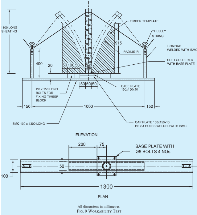
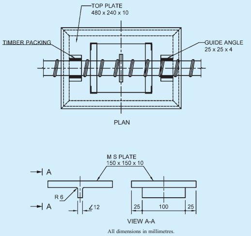
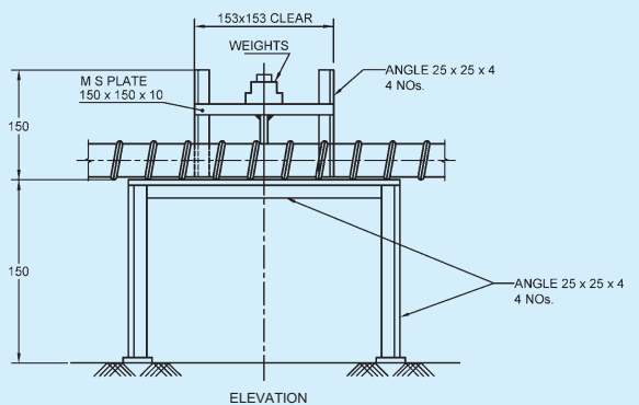
The sheathing ducts shall be either of mild steel as per A-1 or HDPE as per A-2. They shall be in as long lengths as practical from handling and transportation considerations without getting damaged. They shall conform to the requirements specified in A-3 and A-4 and a test certificate shall be furnished by the manufacturer. The tests specified in A-4 are to be performed as part of additional acceptance tests for prestressing systems employing corrugated HDPE sheathing ducts and are not meant for routine site testing purposes.
11.3 Untensioned Steel
11.3.1 Provisions for assembly of reinforcement given in Part 6 ‘Structural Design, Section 5 Concrete, Subsection 5A Plain and Reinforced Concrete’ of the Code shall apply.
11.3.2 The requirements of cover and spacing between bars shall conform to Part 6 ‘Structural Design, Section 5 Concrete, Subsection 5A Plain and Reinforced Concrete’ of the Code.
12Prestressing
12.1 Prestressing Equipment
12.1.1 Tensioning Equipment
12.1.1.1 The requirements of 12.1.1 shall apply to both the pre-tensioned and the post-tensioned methods of prestressing concrete except where specifically mentioned otherwise.
12.1.1.2 Prestressing steel may be tensioned by means of hydraulic or mechanical jacks.
The tension equipment shall be such that it facilitates measurement and control of application of force.
The tensioning equipment should be independently supported so that it does not induce any undesirable secondary stresses.
12.1.1.3 The anchorage provided for the temporary gripping of tendons on the tensioning equipment shall be secure and such as not to damage the tendon.
12.1.1.4 Devices attached to the tensioning equipment for measuring the applied force shall be such that they do not introduce errors exceeding 5 percent.
12.1.2 Temporary Gripping Device
Prestressing tendons may be gripped by wedges, yokes, double cones or any other approved type of gripping devices. The prestressing wires may be gripped singly or in groups. Gripping devices shall be such that in a tensile test, the wire or wires fixed by them would break before failure of the grip itself.
12.1.3 Releasing Device
The releasing device shall be so designed that during the period between the tensioning and release, the tension in the prestressing elements is fully maintained by positive means, such as external anchorages. The device shall enable the transfer of prestress to be carried out gradually so as to avoid large difference of tension between wires in a tendon, severe eccentricities of prestress or the sudden application of stress to the concrete.
12.1.4 Anchorage Device
12.1.4.1 The anchorage device may be patented or otherwise, which complies with the requirements laid down under 12.1.4.2 to 12.1.4.5.
12.1.4.2 The anchoring device shall be strong enough to resist in all respects a force equal to at least the breaking strength of the prestressing tendon it anchors.
12.1.4.3 The anchorage shall transfer effectively and distribute, as evenly as possible, the entire force from the prestressing tendon to the concrete without inducing undesirable secondary or local stresses.
12.1.4.4 The anchorage shall be safe and secure against both dynamic and static loads as well as against impact (see Annex B).
12.1.4.5 The anchorage shall have provision for the introduction of a suitable protective medium, such as cement grout, for the protection of the prestressing steel unless alternative arrangements are made.
12.2Procedure for Tensioning and Transfer
12.2.1 Stressing
12.2.1.1 The tensioning of prestressing tendons shall be carried out in a manner that will induce a smooth and even rate of increase of stress in the tendons. The prestressing shall be controlled by measuring both the force applied to the tendon and the elongation of the tendon.
Stressing schedule shall be incorporated in the design, which may include the following:
a) Details of equipment and procedure for applying prestress, specification of one end or simultaneous stressing from both ends of tendons, stressing in single stage or multiple stages, re-stressing for adjustment of force or for monitoring of force, if required, etc.
b) Calculated amount of tensile force and corresponding expected elongation of each tendon when methods described in (a) are followed.
c) Minimum requirements of strength of concrete at transfer (see also 15.2), stressing sequence
with respect to age of concrete or stage of construction, requirements with respect to grouting operations of neighbouring tendons. Method(s) of measuring force and elongation.
e) Tolerances/limits of variation from design requirements stated in (a) and (b) beyond which reference should be made to the designer. In the absence of any specified provision provided by the designer method described in 12.2.1.3 may be adopted for acceptance.
f) Assumptions made in calculation of force-elongation relationship should be given. These include effective ‘E’ value of tendon, cross sectional area of tendon, coefficient of friction and wobble factor between tendon and duct, assumed slip in anchoring devices if any, efficiency of prestressing jacks where force is measured indirectly by pressure gauges on jacks, corrections to elongation due to changes in gripping length beyond anchorages during stressing and any other relevant information.
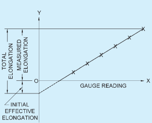
12.2.1.2 Any slack in the prestressing tendon shall first be taken up by applying a small initial tension. The initial tension required to remove slackness shall be taken as the starting point for measuring elongation. Further increase of tension shall be carried out in suitable steps and corresponding elongations noted. The 'force-elongation' relationship shall be recorded in tabular and/or graphical form. The magnitude of initial effective elongation corresponding to initial tension applied to remove slackness shall be obtained from the recorded and linearized portion of measured tension-elongation relationship and added to the measured elongation to give the total elongation. Alternatively, the same correction can be carried out graphically as shown in Fig. 1.
FIG. 1 DETERMINATION OF ACTUAL ELONGATION
12.2.1.3 In practice, the force and elongation of tendon may not exactly match with the expected values given in stressing schedule. In such cases either the force (or the elongation) will be achieved first and the other value lag behind. In such cases the force (or elongation) shall be further increased, but not exceeding 5 percent of the design value till the elongation (or force), which had lagged behind reaches the design value. If, even after reaching 5 percent extra value of the force (or elongation), the other lagged quantity does not reach the design value, reference should be made to the designer for review and corrective action.
12.2.1.4 When two or more prestressing wires or strands are to be tensioned simultaneously by the same tensioning apparatus, care shall be taken to ensure that all such tendons are of the same length from grip to grip.
12.2.1.5 The placement of tendons and the order of stressing and grouting shall be so arranged that the prestressing steel, when tensioned and grouted, does not adversely affect the adjoining ducts.
12.2.2 Measurement of Prestressing Force
12.2.2.1 The force induced in the prestressing tendon shall be determined by means of gauges attached to the tensioning apparatus as well as by measuring the extension of the steel. It is essential that both methods are used jointly so that the inaccuracies to which each is singly susceptible are minimized. Due allowance shall be made for the frictional losses in the tensioning apparatus.
12.2.2.2 All dynamometers and pressure gauges including master gauge shall be calibrated by an approved laboratory immediately prior to use and then at intervals not exceeding 3 months and true force determined from the calibration curve. Further, whenever there is a breakage of tendons, the calibration shall be carried out before reuse of the gauges. The pressure gauges shall be accurate within 2 percent of their full capacity.
12.2.2.3 In measuring the extension of prestressing steel, any slip which may occur in the gripping device shall be taken into consideration.
12.2.3 Breakage of Wires
The breakage of wires in anyone prestressed concrete member shall not exceed 2.5 percent during tensioning. If the breakages are more than 2.5 percent, it shall be examined and corrective actions taken. Wire breakages after anchorage, irrespective of percentage, shall not be condoned without special investigations.
12.2.4 Transfer of Prestressing Force
12.2.4.1 The transfer of the prestress shall be carried
out gradually so as to avoid large differences of tension between wires in a tendon, severe eccentricities of prestressing force and the sudden application of stress to the concrete.
12.2.4.2 Where the total prestressing force in a member is built up by successive transfers to the force of a number of individual tendons on to the concrete, account shall be taken of the effect of the successive prestressing.
12.2.4.3 In the long line and similar methods of prestressing, when the transfer is made on several moulds at a time, care shall be taken to ensure that the prestressing force is evenly applied on all the moulds, and that the transfer of prestress to the concrete is uniform along the entire length of the tension line.
12.3Grouting
The purpose of grouting is to provide permanent protection to the post-tensioned steel against corrosion and to develop bond between the prestressing steel and the surrounding structural concrete. The grout ensures encasement of steel in an alkaline environment for corrosion protection and by filling the duct space, it prevents water collection and freezing.
12.3.1 Materials
12.3.1.1 Water
Only clean potable water free from impurities conforming to 4.4 shall be permitted. No sea or creek water is to be permitted.
12.3.1.2 Cement
Cement used for preparation of grout shall be in accordance with 4.1.
12.3.1.3 Sand
It is not recommended to use sand for grouting of prestressing tendons. In case the internal diameter of the ducts exceeds 150 mm, use of sand may be considered. Sand, if used, shall conform to the accepted standard [6-5B(6)] and shall pass through IS Sieve No. 150. The mass of sand in the grout shall not be more than 10 percent of the mass of cement, unless proper workability can be ensured by addition of suitable plasticizers.
12.3.1.4 Chemical admixtures
Chemical admixtures conforming to the accepted standard [6-5B(20)] may be used if tests have shown that their use improves the properties of grout, that is, increasing fluidity, reducing bleeding, entraining air or expanding the grout. Admixtures shall not contain chlorides, nitrates, sulphides, sulphites or any other products which are likely to damage the steel or grout.
When an expanding agent is used, the total unrestrained expansion shall not exceed 10 percent. Aluminium powder as an expanding agent is not recommended for grouting because its long term effects are not free from doubt.
12.3.1.5 Sheathing
For requirements of sheathing, 11.2 shall be referred.
12.3.1.6 Grout openings or vents
a) All ducts should have grout opening at both ends. For this purpose special openings should be provided where such openings are not available at end anchorages. For draped (curved) cables crown points should have a grout vent. For draped cables longer than 50 m grout vents or drain holes may be provided at or near the lowest points. It is a good practice to provide additional air vents at suitable intervals. All grout openings or vents should include provisions for preventing grout leakage.
b) Standard details of fixing couplers, inlets, outlets and air vents to the duct/anchorage shall be followed as recommended by the supplier of the system of prestressing.
Ducts should be securely fastened at close intervals. All unintended holes or openings in the duct shall be repaired prior to concrete placing. The joints of the couplers and the sheathing should be made water proof by use of tape or similar suitable system capable of giving leak proof joints. Grout openings and vents shall be securely anchored to the duct and to either the forms or to reinforcing steel to prevent displacement during concreting operations due to weight, buoyancy and vibrations.
Ducts require very careful handling as, being of thin metal, they are susceptible to leakage due to corrosion in transit or storage, by tearing ripping in handling particularly when placed adjoining to reinforcing steel, by pulling apart of joints while inserting tendons prior to concreting, or by accidental puncturing while drilling for form ties/inserts or by sparks from welding being done close by. Care shall be taken to avoid any damage by rough use of internal vibrator. Such local damage shall be repaired using tape to make it water tight to prevent ingress of slurry from the fresh concrete.
12.3.2 Equipment
12.3.2.1 Grout colloidal mixer
It is essential that the grout is maintained in a homogenous state and of uniform consistency by use of suitable agitator so that there is no separation of cement during entire grouting process. It is, therefore
necessary that the grout be continuously mixed in a colloidal mixer with a minimum speed of 1 000 rpm and travel of discharge not exceeding 15 m/s.
12.3.2.2 Grout pump
The pump should be positive displacement type and should be capable of injecting the grout in a continuous operation and not by way of pulses. The grout pump shall be fitted with a pressure gauge to enable pressure of injection to be controlled. The minimum pressure at which grout should be pumped shall be 0.3 MPa and the grout pump shall have a relief arrangement for bypass of the grout in case of built up of pressure beyond 1 MPa. The capacity of the grout pump should be such as to achieve a forward speed of grout of around 5 to 10 m/min. The slower rates are preferable as they reduce the possibility of occurrence of voids. If the capacity of the pump is large, it is usual to grout two or more cables simultaneously through a common manifold.
Use of hand pumps for grouting is not recommended. Use of compressed air operated equipment for injection is prohibited as it is likely that there will be some air entrapped in grout.
12.3.2.3 Water pump
Before commencement of grouting, a stand by direct feed high pressure water pump should be available at site for an emergency.
In case of any problem in grouting the ducts, such pump shall immediately be connected to the duct and all grout flushed by use of high pressure water flushing. It is, therefore, necessary to have adequate storage of clean potable water for operation of the water pump for such emergencies.
12.3.2.4 Grout screen
The grouting equipment should contain a screen having a mesh size of IS Sieve No. 106 (IS Sieve No. 150, if sand is used). Prior to introduction into the grout pump, the grout should be passed through such screen. This screen should be easily accessible for inspection and cleaning.
12.3.2.5 Connections and air vents
Standard details of fixing inlets, outlets, and air vents to the sheathing and/or anchorage should be followed as recommended by specialist supplier of the system of prestressing. In general, all connections are to be of the ‘Quick couple’ type and at change of diameters suitable reducers are to be provided.
12.3.3 Properties of the Grout
Water-cement ratio should be as low as possible, consistent with workability. This ratio should not normally exceed 0.45.
The temperature of the grout after accounting for the ambient temperature of the structure shall not exceed 25° C.
Before grouting, the properties of the grout mix should be tested in a laboratory depending on the facilities available. Tests should be conducted for each job periodically. The recommended test is described below.
The compressive strength of 100 mm cubes of the grout shall be not less than 27 MPa at 28 days. Cubes shall be cured in a moist atmosphere for the first 24 h and subsequently in water. These tests shall be conducted in advance to ascertain the suitability of the grout mix.
Chlorides from all sources, that is, cement, water, sand, fillers and admixture should not exceed 0.1 percent by mass of the cement.
12.3.4 Mixing of Grout
Proportions of materials should be based on field trials made on the grout before commencement of grouting, but subject to the limits specified above. The materials should be measured by weight.
Water should be added to the mixer first, following by Portland cement and sand, if used. Admixture, if any, may be added as recommended by the manufacturer.
Mixing time depends upon the type of the mixer but will normally be between 2 and 3 min. However, mixing should be for such a duration as to obtain uniform and thoroughly blended grout, without excessive temperature increase or loss of expansive properties of the admixtures. The grout should be continuously agitated until it is injected.
Once mixed, no water shall be added to the grout to increase its fluidity.
Hand mixing is not permitted.
7.2Requirements for Durability
7.2.1 Shape and Size of Member
The shape or design details of exposed structures should be such as to promote good drainage of water and to avoid standing pools and rundown of water. Care should also be taken to minimize any cracks that may collect or transmit water. Adequate curing is essential to avoid the harmful effects of early loss of moisture. Member profiles and their intersections with other members shall be designed and detailed in a way to ensure easy flow of concrete and proper compaction during concreting.
Concrete is more vulnerable to deterioration due to chemical or climatic attack when it is in thin sections, in sections under hydrostatic pressure from one side only, in partially immersed sections and at corners and edges of elements. The life of the structure can be lengthened by providing extra cover to steel, by chamfering the corners or by using circular cross-sections or by using surface coatings which prevent or reduce the ingress of water, carbon dioxide or aggressive chemicals.
7.2.2 Exposure Conditions
7.2.2.1 General environment
The general environment to which the concrete will be exposed during its working life is classified into five levels of severity, that is, mild, moderate, severe, very severe and extreme as described in Table 2.
7.2.2.2 Abrasion
Abrasion of concrete surfaces results from friction, which may cause a grinding action; or by repetitive impact and overloading, which causes local crushing.
Abrasion resistant surfaces primarily involve consideration of surface finishing technique curing regime, aggregate characteristics and cement content. Compressive strength of concrete may also provide a relative indication of resistance.
Concrete surfaces protected against weather or aggressive conditions, except those situated in coastal areas
ii)
Moderate
Concrete surfaces sheltered from severe rain or freezing whilst wetConcrete exposed to condensation and rainConcrete continuously under waterConcrete in contact or buried under non-aggressive soil/ground waterConcrete surfaces sheltered from saturated salt air in coastal area
iii)
Severe
Concrete surfaces exposed to severe rain, alternate wetting and drying or occasional freezing whilst wet or severe condensationConcrete completely immersed in sea waterConcrete exposed to coastal environment
iv)
Very severe
Concrete surfaces exposed to sea water spray, corrosive fumes or severe freezing conditions whilst wetConcrete in contact with or buried under aggressive sub-soil/ground water
v)
Extreme
Surface of members in tidal zone and splash zoneMembers in direct contact with liquid/solid aggressive chemicals
Specialist literatures may be referred to for durability requirements of concrete surfaces exposed to abrasive action, for example in case of machinery and metal tyres.
7.2.2.3 Freezing and thawing
Where freezing and thawing actions under wet conditions exist, enhanced durability can be obtained by the use of suitable air entraining admixtures. When concrete lower than grade M 50 is used under these conditions, the mean total air content by volume of the fresh concrete at the time of delivery into the construction should be as follows:
Nominal Maximum Aggregate Size mm
Entrained Air Percentage
10
7 ± 1
20
5 ± 1
40
4 ± 1
Since air entrainment reduces the strength, suitable adjustments may be made in the mix design for achieving required strength.
7.2.2.4 Exposure to sulphate attack
Table 3 gives recommendations for the type of cement, maximum free water/cement ratio and minimum cement content, which are required at different sulphate concentrations in near actual ground water having pH of 6 to 9.
For the very high sulphate concentrations in Class 5 conditions, some form of lining such as polyethylene or polychloroprene sheet; or surface coating based on asphalt, chlorinated rubber, epoxy, or polyurethane materials should also be used to prevent access by the sulphate solution.
7.2.3 Requirement of Concrete Cover
7.2.3.1 The protection of the steel in concrete against corrosion depends upon an adequate thickness of good quality concrete.
7.2.3.2 The nominal cover to the reinforcement shall be provided as per 25.4 of Part 6 ‘Structural Design, Section 5 Concrete, Subsection 5A Plain and Reinforced Concrete’ of the Code.
7.2.4 Concrete Mix Proportions
7.2.4.1 General
The free water cement ratio is an important factor in governing the durability of concrete and should always be the lowest value. Appropriate value for minimum cement content and the maximum free water-cement ratio are given in Table 4 for different exposure conditions. The minimum cement content and maximum water-cement ratio apply to 20 mm nominal maximum size aggregate. For other sizes of aggregate they should be changed as given in Table 5.
7.2.4.2 Maximum cement content
Cement content in excess of 450 kg/m³ should not be used unless special consideration has been given in design to the increased risk of cracking due to drying shrinkage in thin sections, or to thermal stresses in thicker sections.
7.2.5 Mix Constituents
7.2.5.1 General
For concrete to be durable, careful selection of the mix and materials is necessary, so that deleterious constituents do not exceed the limits.
7.2.5.2 Chlorides in concrete
Whenever there is chloride in concrete there is an increased risk of corrosion of embedded steel. The higher the chloride content, or if subsequently exposed to warm moist conditions, the greater the risk of corrosion. All constituents may contain chlorides and concrete may be contaminated by chlorides from the external environment. To minimize the chances of deterioration of concrete from harmful chemical salts, the levels of such harmful salts in concrete coming from concrete materials, that is, cement, aggregates, water and admixtures, as well as by diffusion from the environment should be limited. The total amount of
Table 3Requirements for Prestressed Concrete Exposed to Sulphate Attack (Clauses 7.2.2.4 and 8.1.2)
Sl No.
Class
Concentration of Sulphates, Expressed as SO3
Type of Cement
Dense, Fully Compacted Concrete, made with 20 mm Nominal Maximum Size Aggregates Complying with the Accepted Standard [6-5B(6)]
In Soil
In Ground Water
Total SO3
SO3 in 2:1 Water: Soil Extract
Percent
g/l
g/l
Minimum Cement Content kg/m3
Maximum Free Water-Cement Ratio
(1)
(2)
(3)
(4)
(5)
(6)
(7)
(8)
i)
1
Traces (<0.2)
Less than 1.0
Less than 0.3
Ordinary Portland cement or Portland slag cement or Portland pozzolana cement
280
0.55
ii)
2
0.2 - 0.5
1.0 - 1.9
0.3 - 1.2
Ordinary Portland cement or Portland slag cement or Portland pozzolana cement
330
0.50
Supersulphated cement or sulphate resisting Portland cement
310
0.50
iii)
3
0.5 - 1.0
1.9 - 3.1
1.2 - 2.5
Supersulphated cement or sulphate resisting Portland cement
330
0.50
Portland pozzolana cement or Portland slag cement
7.2.6 Concrete in Aggressive Soils and Water
7.2.6.1 General
The destructive action of aggressive waters on concrete is progressive. The rate of deterioration decreases as the concrete is made stronger and more impermeable, and increases as the salt content of the water increases. Where structures are only partially immersed or are in contact with aggressive soils or waters on one side only, evaporation may cause serious concentrations of salts with subsequent deterioration, even where the original salt content of the soil or water is not high.
NOTE — Guidance regarding requirements for concrete exposed to sulphate attack is given in 7.2.2.4.
7.2.6.2 Drainage
At sites where alkali concentrations are high or may become very high, the ground water should be lowered by drainage so that it will not come into direct contact with the concrete.
Additional protection may be obtained by the use of impermeable barriers.
7.2.7 Compaction, Finishing and Curing
Adequate compaction without segregation should be ensured by providing suitable workability and by employing appropriate placing and compacting equipment and procedures. Full compaction is particularly important in the vicinity of construction and movement joints and of embedded water bars and reinforcement.
Good finishing practices are essential for durable concrete.
Overworking the surface and the addition of water-cement to aid in finishing should be avoided; the resulting laitance will have impaired strength and durability and will be particularly vulnerable to freezing and thawing under wet conditions.
It is essential to use proper and adequate curing techniques to reduce the permeability of the concrete and enhance its durability by extending the hydration of the cement, particularly in its surface zone (see also provisions on curing under 13).
13Transporting, Placing, Compacting and Curing
13.1 Provisions given Part 6 ‘Structural Design, Section 5 Concrete, Subsection 5A Plain and Reinforced Concrete’ of the Code shall apply. In addition, the provisions given in 13.1.1 and 13.1.2 shall also apply.
13.1.1 Jointing of Butted Assemblies
13.1.2 The joints of butted assemblies shall be made of either cement grout or cement mortar or concrete. Cement grouting shall be used for joints up to 12 mm
thick. For joints thicker than 12 mm and up to 75 mm, cement mortar shall be used. The mortar which may be made of one part cement and one-and-a-half parts sand shall be of a dry consistency and shall be packed hard in layers so that it rings true. Where joints exceeding 75 mm are encountered, the joint shall be made up of concrete. Use of epoxy may be permitted with the approval of engineer-in-charge.
13.1.2.1 The stressing operations may be carried out in case of mortar joints immediately after placing the mortar but the stress in the mortar shall not exceed 7.0 N/mm² . In the case of grouted joints and concrete joints the allowable stress in the first 24 h after placing of the grout or concrete in the joint shall approximate as closely as possible to the strength of the grout or concrete used.
13.1.3 The holes for the prestressing tendons shall be accurately located and shall be in true alignment when the units are put together.
13.1.4 Full tensioning shall not be carried out until the strength of the concrete or mortar in the joint has reached twice the stress at transfer.
17Inspection and Testing of Structures
The provision of Part 6 ‘Structural Design, Section 5
Concrete, Subsection 5A Plain and Reinforced Concrete' of the Code shall apply, except for the following:
a) The test load specified in 16.6.2 of Part 6 ‘Structural Design, Section 5 Concrete, Subsection 5A Plain and Reinforced Concrete’ of the Code shall be limited to full dead load of the structure plus design imposed load.
b) For Type 1 and Type 2 structures (see 19.3.2), if within 24 h of removal of the imposed load, the structure does not recover at least 85 percent of the deflection under imposed load, the test may be repeated after a lapse of 72 h. If the recovery is less than 90 percent, the structure shall be deemed to be unacceptable.
c) For Type 3 structures (see 19.3.2), if within 24 h of the imposed load, the structure does not recover at least 75 percent of the deflection under imposed load, the test may be repeated after a lapse of 72 h. If the recovery is less than 80 percent, the structure shall be deemed to be unacceptable.
Section 5B (C) General Design Requirements
12.4Grouting Operations
12.4.1 General
a) Grouting shall be carried out as early as possible but not later than 2 weeks of stressing a tendon. Whenever this stipulation cannot be complied with for unavoidable reasons, adequate temporary protection of the steel against corrosion by methods or products which will not impair the ultimate adherence of the injected grout should be ensured till grouting. The sealing of the anchorage ends after concreting is considered to be a good practice to prevent ingress of water. For structures in aggressive environment, sealing of the anchorage ends is mandatory.
b) Any traces of oil if applied to steel for preventing corrosion should be removed
before grouting operation.
Ducts shall be flushed with water for cleaning as well as for wetting the surfaces of the duct walls. Water used for flushing should be of same quality as used for grouting. It may, however, contain about 1 percent of slaked lime or quick lime. All water should be drained through the lowest drain pipe or by blowing compressed air through the duct.
d) The water in the duct should be blown out with oil free compressed air.
Blowing out water from duct for cables longer than 50 m draped up at both ends by compressed air is not effective, outlet/vent provided at or near the lowest point shall be used to drain out water from duct.
e) The connection between the nozzle of the injection pipe and duct should be such that air cannot be sucked in.
f) All outlet points including vent openings should be kept open prior to commencement of injection grout.
g) Before grouting, all air in the pump and hose should be expelled. The suction circuit of the pump should be air-tight.
12.4.2 Injection of Grout
a) After mixing, the grout shall be kept in continuous movement.
b) Injection of grout be continuous and should not be interrupted.
c) For vertical cable or cables inclined more than 60° to the horizontal injection shall be effected from the lowest anchorage or vent of the duct.
d) The method of injection shall ensure complete filling of the ducts. To verify this, it is advisable to compare the volume of the space to be filled by the injected grout with the quantity or grout actually injected.
e) Grouting should be commenced initially with a low pressure of injection of up to 0.3 MPa increasing it until the grout comes out at the other end. The grout may be allowed to flow freely from the other end until the consistency of the grout at this end is the same as that of the grout at the injection end. When the grout flows at the other end, it should be closed off and buildup of pressure commenced. Full injection pressure of about 0.5 MPa shall be maintained for at least 1 min before closing the injection pipe. It is a recommended practice to provide a stand pipe at the highest point of the tendon profile to hold all water displaced by sedimentation or bleeding. If
there is a buildup of pressure much in excess of 1 MPa without flow of grout coming at the other end, the grouting operation shall be discontinued and the entire duct flushed with high pressure water. Also, the bypass system indicated in 12.3.2.2 is essential for further safety.
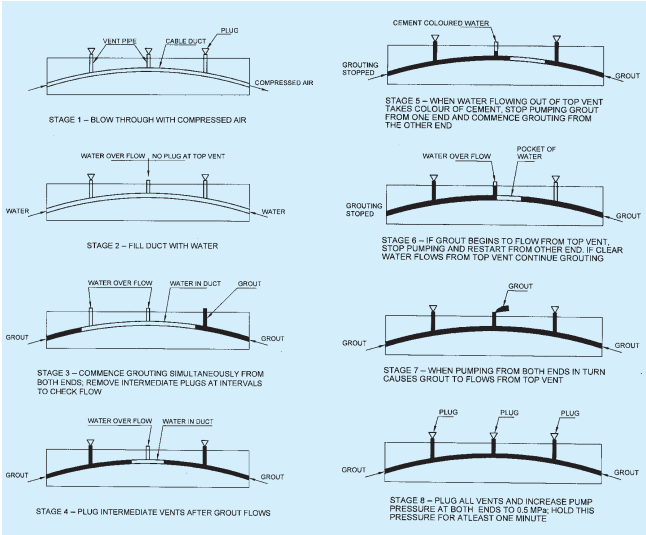
f) In the case of cables draped downwards for example, in cantilever construction simultaneous injection from both ends may be adopted (see Fig. 2).
g) Grout not used within 30 min of mixing should be rejected.
h) Disconnection is facilitated if a short length of flexible tube connects the duct and injection pipe. This may be squeezed and cut off after the grout has hardened.
12.4.3 Precautions and Recommendations for Effective Grouting
a) In cold and frosty weather, injection should
be postponed unless special precautions are taken. If frost is likely to occur within 48 h after injection, heat shall be applied to the member and maintained for at least 48 h after injection so that the temperature of the grout does not fall below 5° C. Prior to commencement of grout, care shall be taken to ensure that the duct is completely free of frost/ice by flushing with warm water but not with steam.
b) When the ambient temperature during the day is likely to exceed 40° C, grouting should be done in the early morning or late evening hours.
c) When the cables are threaded after concreting, the duct shall be temporarily protected during concreting by inserting a stiff rod or a rigid PVC pipe or any other suitable method.
d) During concreting, care shall be taken to ensure that the sheathing is not damaged.
FIG. 2 PROCEDURE FOR GROUTING OF CABLES DRAPED DOWNWARDS
Needle vibrators shall be used with extreme care by well experienced staff only, to ensure the above requirements.
e) It is a good practice to move the cables in both directions during the concreting operations. This can easily be done by light hammering the ends of the wires/strands during concreting. It is also advisable that 3 h to 4 h after concreting the cable should be moved both ways through a distance of about 200 mm. With such movement, any leakage of mortar which has taken place in spite of all precautions loses bond with the cables, thus reducing the chance of blockages. This operation can also be done by fixing prestressing jacks at one end pulling the entire cable and then repeating the operation by fixing the jack at the other end.
f) The cables to be grouted should be separated by as much distance as possible.
g) In case of stage prestressing, cables tensioned in the first stage should not remain ungrouted till all cables are stressed. It is a good practice, while grouting any duct in stage prestressing, to keep all the remaining ducts filled up with water containing 1 percent lime or by running water through such ducts till the grout has set. After grouting the particular cable, the water in the other cables should be drained and removed with compressed air to prevent corrosion.
h) Care should be taken to avoid leaks from one duct to another at joints of precast members.
j) End faces where anchorages are located are vulnerable points of entry of water. They have to be necessarily protected with an effective barrier. Recesses should be packed with mortar concrete and should preferably be painted with water proof paint.
k) After grouting is completed, the projecting portion of the vents should be cut off and the face protected to prevent corrosion.
14Concreting under Special Conditions
14.1 Work in Extreme Weather Conditions
During hot or cold weather, the concreting should be done as per the procedure set out in good practices [6-5B(21)].
18.3Deductions for Prestressing Tendons
The deductions for prestressing tendons as in 18.3.1 shall be considered for the determination of area, centroid and moment of inertia of the cross-section.
18.3.1 In calculating area, centroid and moment of inertia of a cross-section, deduction (or addition in case of transformed area of tendons) for prestressing tendons shall be made as follows:
a) In the case of pre-tensioned members, where the prestressing tendons are single wires distributed on the cross-section or strands of wires of relatively small cross-sectional area, allowance for the prestressing tendons need not be made. Where allowance is made, it shall be on the basis of (m-1) times the area of the
prestressing tendons, m being the modular ratio.
b) In the case of post-tensioned members, deductions shall invariably be made for prestressing tendons, cable ducts or sheaths and such other openings whether they are formed longitudinally or transversally. These deductions need not, however, be made for determining the effect of loads applied after the ducts, sheaths or openings have been grouted or filled with concrete. Where such deductions are not made, a transformed area equivalent to (m-1) times the area of the prestressing tendon shall be taken in calculation, m being the modular ratio.
NOTE — m shall be calculated as Es/Ec ; for values of Es and Ec , see 4.6.1.2.1 and 5.2.3.1, respectively. Wherever necessary, creep effects shall also be taken into consideration.
c) In case of multi-directional prestressing, loss of area due to presence of ungrouted ducts/sheaths placed at an angle to the prestressing tendons under consideration may be made at full area (100 percent) of such ducts. In case, such ducts placed at an angle have been grouted prior to stressing of tendons 50 percent of area of such ducts can be considered as effectively available.
18.4Instability During Erection
In evaluating the slenderness effects during lifting of slender members following factors require consideration:
a) Member geometry,
b) Location of lifting points,
c) Method of lifting, and
d) Tolerances in construction.
All beams, which are lifted on vertical or inclined slings, shall be checked for lateral stability and lateral moment on account of tilting of beam due to inaccuracies in location of lifting points, and due to the lateral bow.
For calculating the factor of safety against lateral instability (γj) references may be made to specialist literature; the factor shall not be less than two.
For determining the lateral moment due to tilting, realistic values which are not likely to be exceeded in practice shall be assumed for the eccentricity of lifting points and the lateral bow. The maximum tensile stress for γi/(γi-1) times the lateral moment due to tilting shall not exceed 1.5 N/mm² .
18.6Considerations Affecting Design Details
18.6.1 Transmission Zone in Pre-Tensioned Members
18.6.1.1 Transmission length
The considerations affecting the transmission length shall be as follows:
a) The transmission length depends on a number of variables, the most important being the strength of concrete at transfer, the size and
type of tendon, the surface deformations of the tendon. The transmission length of the tendon towards the top of a unit is usually greater than that at the bottom.
The following values may be used, provided the concrete is well-compacted and detailing is as per the relevant provisions of this Section, and its strength at transfer is not less than 35 N/mm² and the tendon is released gradually:
For plain and indented wire : 100φ
For crimped wires : 65φ
Strands : 30φ
c) The development of stress in the tendon may be assumed to vary linearly along the length of the member.
NOTES
1 φ is the diameter of the tendon.
2 The transmission length may vary depending on the site conditions and therefore should be determined from tests carried out under the most unfavourable conditions.
18.6.2 End Zone in Post-Tensioned Members
18.6.2.1 Bearing stress
a) On the areas immediately behind external anchorages, the permissible unit bearing stress on the concrete, after accounting for losses due to elastic shortening and seating of anchorages, shall not exceed,
18General Design Requirements
18.1 General
The general design requirements for design of prestressed concrete structures shall be as per 17 to 23 of Subsection 5A(C) of Part 6 ‘Structural Design, Section 5 Concrete, Subsection 5A Plain and Reinforced Concrete’ of the Code except as modified and supplemented in 18.2 to 18.6.5.
18.2 Effects of Prestress
The effects of prestress shall also be taken into account in assessing loads and forces.
18.5Prestressing Requirements
18.5.1 Maximum Initial Prestress
At the time of initial tensioning, the maximum tensile
stress, fpi immediately behind the anchorages shall not exceed 76 percent of the ultimate tensile strength, fpu of the wire or bar or strand.
18.5.2 Losses in Prestress
While assessing the stresses in concrete and steel during tensioning operations and later in service, due regard shall be paid to all losses and variations in stress from creep of concrete, shrinkage of concrete, relaxation of steel, the shortening (elastic deformation) of concrete at transfer, and friction and slip of anchorage. Unless otherwise determined by actual tests, allowance for these losses shall be made in accordance with the values specified under 18.5.2.1 to 18.5.2.6.
18.5.2.1 Loss of prestress due to creep of concrete
The loss of prestress due to creep of concrete under load shall be determined for all the permanently applied loads including the prestress.
The creep loss due to live load stresses, erection stresses and other stresses of short duration may be ignored. The loss of prestress due to creep of concrete is obtained as the product of the modulus of elasticity of the prestressing steel and the ultimate creep strain of the concrete fibre integrated along the line of centre of gravity of the prestressing tendon at the section at which creep loss is being calculated for bonded tendons. In case of unbonded tendons, the creep loss is a product of modulus of elasticity of prestressing steel and creep strain calculated by integrating and averaging creep stress along the line of centre of gravity between the anchorage points.
The total creep strain during any specific period shall be assumed for all practical purposes, to be the creep strain due to sustained stress equal to the average of the stresses at the beginning and end of the period.
18.5.2.2 Loss of prestress due to shrinkage of concrete
The loss of prestress due to shrinkage of concrete shall be the product of the modulus of elasticity of prestressing steel and the shrinkage strain of concrete calculated as per 5.2.4.
18.5.2.3 Loss of prestress due to relaxation of steel
The relaxation losses in prestressing steels vary with type of steel, initial prestress, age, and temperature and, therefore, shall be determined from experiments. When experimental values are not available, the relaxation losses may be assumed as given in Table 6.
εca
where
εcs=total shinkage strain;
εcd=drying shrinkage strain; and
εca=autogenous shrinkage strain.
5.2.4.2 The autogenous shrinkage strain develops during hardening of concrete; the major part develops in the early days after casting. Autogenous shrinkage is a linear function of concrete strength. It should be considered specifically when new concrete is cast against hardened concrete.
In the absence of accurate field/laboratory data, the following values may be considered in design:
Grade of Concrete
Autogenous Shrinkage( ca × 106)
M 30
35
M 35
45
M 45
65
M 50
75
M 60
95
5.2.4.3 The drying shrinkage strain develops slowly, as it is a function of migration of the water through the hardened concrete.
The final value of the drying shrinkage strain, cd,∞ may be taken as equal to kh· cd Values of cd may be taken from the table given below for guidance. These values are expected mean values, with a coefficient of variation of about 30 percent.
fck MPa
Unrestrained Drying Shrinkage Values ( cd × 106) for Concrete with PortlandCement for Relative Humidity
50 percent(2)
80 percent(3)
25
535
300
50
420
240
75
330
190
NOTE — The values for the other designated grades may be obtained by interpolation.
kh is a coefficient depending on the notional size h₀, as given below:
h₀
k<sub>h</sub>
mm
100
1.0
200
0.85
300
0.75
≥ 500
0.70
5.2.4.4 The development of autogenous shrinkage with time may be taken as:
εca(t)=βas(t).εca
where
β as(t) = 1 - (-0.2√(t) ) where, t is in days.
5.2.4.5 The development of the drying shrinkage strain in time may be taken as:
εcd(t)=βds(t,ts).kh.εcd
βds(t,ts)=(t−ts)+0.04h03
where
t = age of the concrete at the moment considered, in days;
ts = age of the concrete at the beginning of drying shrinkage, in days; normally this is at the end of curing; and
h₀ = notional size of the cross-section, in mm
= 2Ac/u , where Ac is the concrete cross-sectional area and u is the perimeter of that part of the cross-section which is exposed to drying.
ci
(
t0
)
εcc(t)
where
εcc(t)=creep strain at timet>t0,
εcl(t0)=initial strain at loading, and
t0=initial time of loading.
The creep coefficient φ (t,t₀) is given by:
φ (t, t ₀) = φ₀ β (t, t ₀),
where
φ₀ = notional creep coefficient to which the creep co-efficient reaches asymptotically with time (this can be taken as value reached in 70 years), and
β (t,t₀) = coefficient describing development of creep with time (see 5.2.5.2).
The notional creep coefficient φ₀ is given by:
φ₀ = φRH β (f cm) β (t ₀)
where
φRH = factor to allow for the effect of relative humidity on the notional creep coefficient
=1+0.13h01−RH/100forfck≤45MPa=[1+0.13h0
RH = relative humidity of the ambient environment in percent;
h₀ = notional size of the member, in mm;
= 2 A c / u;
Ac = cross-sectional area, and
u = perimeter of the member in contact with the atmosphere;
β(fcm)= factor to allow for the effect of concrete strength on the notional creep coefficient
=fck+816.8
β (t₀) = factor to allow for the effect of concrete age at loading on the notional creep coefficient
=(0.1+t00.20)1
Where end results are not sensitive to precise values calculated as given above, the values given in the table below can be considered as final creep coefficient for design for normal weight concrete of grades between M 30 and M 60, subject to condition that the compressive stress does not exceed 0.36 fck at the age of loading, and mean temperature of concrete is between 10°C and 20°C with seasonal variation between -20°C and 40°C . For temperature greater than 40°C the coefficient given may be increased by 10 percent in absence of accurate data.
Age at Loading t₀ (days)
Creep Coefficient φo (70 yr, t₀ ) of an Ordinary Structural Concrete after 70 Years of Loading
Under Dry Atmospheric Conditions(RH 50 Percent)Notional Size( 2Ac/u )
Under Humid Atmospheric Conditions(Outdoor)(RH 80 Percent)Notional Size( 2Ac/u )
50 mm(2)
150 mm(3)
600 mm(4)
50 mm(5)
150 mm(6)
600 mm(7)
1
5.8
4.8
3.9
3.8
3.4
3.0
7
4.1
3.3
2.7
2.7
2.4
2.1
28
3.1
2.6
2.1
2.0
1.8
1.6
90
2.5
2.1
1.7
1.6
1.5
1.3
365
1.9
1.6
1.3
1.2
1.1
1.0
5.2.5.2 The development of creep with time may be taken as φ(t,t₀)=β(t,t₀)φ₀
| β (t, t 0 ) = [ t - t 0β H + (t - t 0 ) ] 0. 3 |
where
t = age of concrete in days at the moment considered;
t₀ = age of concrete at loading, in days;
(t - t₀) = duration of loading, in days; and
βH = a coefficient depending on the relative humidity (RH in percent) and the notional member size ( h₀ in mm).
=1.5[1+(1.2RH0RH)18]h
where
RH = relative humidity expressed as percent.
RH₀ = 100 (that is, 100 percent relative humidity).
α₁, α₂, α₃ = coefficients to consider the influence of the concrete strength,
as specified. The steel inside ducts is best protected in long terms by cement grouts which are properly executed following recommendations given in 12.
The protection by grouting can be further augmented by use of methods given below:
a) Use of coated steel using Zn, Zn + Al or epoxy.
b) Use of non-corroding impervious sheathing material like HDPE is beneficial. However, bond between sheathing and concrete and sheathing and grout shall be adequate as needed by design. This method is particularly suitable in presence of migrating water or variable drying/wetting condition of concrete of severe external penetration of corrosive agents.
External parts of anchorages and projecting cables should be covered by suitable casing and protected by suitable material and method.
11.1.5.4 Protection during construction period
a) The prestressing steel, sheathing and anchorages shall be manufactured, transported and stored at site in such a way as to provide them with adequate corrosion protection. Use of proper packaging and provision of externally applied passivating agents, oil films, etc, which is carried over in factory itself is recommended.
b) If prestressing steel/metallic sheathing material is left unprotected at site or embedded in concrete during construction period longer than two weeks, it shall be protected by flushing with oil/water mixture (for example cutting oil) with periodic re-flushing at not more than three months interval.
c) After stressing, the sheaths/steel shall be provided with permanent protection as soon as possible, preferably within one week. While providing protection by pressure grouting of cement care should be taken that the neighbouring cables are not penetrated by grout. In case of doubt such cables shall be grouted in immediate sequence before the earlier grout could have set. If the earlier stressed cables are not grouted to avoid this problem, they should be protected by periodic flushing by oil/water mixture as given in (b).
350
0.45
iv)
4
1.0 - 2.0
3.1 - 5.0
2.5 - 5.0
Supersulphated or sulphate resisting Portland cement
370
0.45
v)
5
More than 2.0
More than 5.0
More than 5.0
Sulphate resisting Portland cement or supersulphated cement with protective coatings
400
0.40
NOTES
1 Cement content given in this table is irrespective of grades of cement. Suitable adjustment may be made in the minimum cement content specified in case of use of aggregate other than 20 mm nominal maximum size.
2 Use of supersulphated cement is generally restricted where the prevailing temperature is above 40 °C.
3 Supersulphated cement gives an acceptable life provided that the concrete is dense and prepared with a water-cement ratio of 0.4 or less, in mineral acids, down to pH 3.5.
4 The cement contents given in col 7 of this table are the minimum recommended. For SO3contents near the upper limit of any class, cement contents above these minimum are advised.
5 For severe conditions, such as thin sections under hydrostatic pressure on one side only and sections partly immersed, considerations should be given to a further reduction of water-cement ratio.
6 Portland slag cement with slag content more than 50 percent exhibits better sulphate resisting properties.
7 Where chloride is encountered along with sulphates in soil or ground water, ordinary Portland cement with C3A content from 5 to 8 percent shall be desirable to be used in concrete, instead of sulphate resisting cement.
acid soluble chloride content (as Cl) in the concrete at the time of placing shall be not more than 0.4kg / m³ of concrete.
The total acid soluble chloride content should be calculated from the mix proportions and the measured chloride contents of each of the constituents. Wherever possible, the total chloride content of the concrete should be determined.
7.2.5.3 Sulphates in concrete
Sulphates are present in most cements and in some aggregates; excessive amounts of water-soluble sulphate from these or other mix constituents can cause expansion and disruption of concrete. To prevent this, the total water-soluble sulphate content of the concrete mix, expressed as SO₃ (where SO₃=0.833 SO₄ ) should
not exceed 4 percent by mass of the cement in the mix. The sulphate content should be calculated as the total from the various constituents of the mix.
7.2.5.4 Alkali-aggregate reaction
Some aggregates containing particular varieties of silica may be susceptible to attack by alkalis ( Na₂O and K₂O ) originating from cement or other sources, producing an expansive reaction which can cause cracking and disruption of concrete. Damage to concrete from this reaction will normally occur only when all the following are present together:
a) A high moisture level, within the concrete;
b) A cement with high alkali content, or another source of alkali; and
c) Aggregate containing an alkali reactive constituent.
Table 4Minimum Cement Content, Maximum Water-Cement Ratio and Minimum Grade of Concrete for Different Exposures with Normal Weight Aggregates of 20 mm Nominal Maximum Size (Clauses 7.2.4.1 and 8.1.2)
Sl No.
Exposure
Prestressed Concrete
Minimum Cement Content kg/m³
Maximum Free Water Cement Ratio
Minimum Grade of Concrete
(1)
(2)
(3)
(4)
(5)
i)
Mild
300
0.55
M 30
ii)
Moderate
300
0.50
M 30
iii)
Severe
320
0.45
M 30
iv)
Very severe
340
0.45
M 35
v)
Extreme
360
0.40
M 40
1 Cement content prescribed in this table is irrespective of the grades and types of cement and it is inclusive of additions mentioned in 4.2. The additions such as fly ash or ground granulated blast furnace slag may be taken into account in the concrete composition with respect to the cement content and water-cement ratio if the suitability is established and as long as the maximum amounts taken into account do not exceed the limit of pozzolana as specified in the accepted standard [6-5B(11)] and that of slag as specified in the accepted standard [6-5B(12)] beyond which these additions, though permitted, shall not be considered for these purposes.
2 The minimum cement content, maximum free water-cement ratio and minimum grade of concrete are individually related to exposure.
Table 5Adjustments to Minimum Cement Contents for Aggregates Other than 20 mm Nominal Maximum Size (Clause 7.2.4.1)
Sl No.
Nominal Maximum Aggregate Size mm (2)
Adjustments to Minimum Cement Contents in Table 4 kg/m3 (3)
i)
10
+40
ii)
20
0
iii)
40
-30
Where the service records of particular cement/aggregate combination are well established, and do not include any instances of cracking due to alkali-aggregate reaction, no further precautions should be necessary. When the materials are unfamiliar, precautions should take one or more of the following forms:
a) Use of non-reactive aggregate from alternate sources.
b) Use of low alkali ordinary Portland cement having total alkali content not more than 0.6 percent [as Na₂O equivalent (expressed as Na₂O + 0.678 K₂O )].
Further advantage can be obtained by use of fly ash conforming to the accepted standard [6-5B(13)] or granulated blast furnace slag conforming to the accepted standard [6-5B(14)] as part replacement of ordinary Portland cement (having total alkali content as Na₂O equivalent not more than 0.6 percent), provided fly ash content is at least 20 percent or slag content is at least 50 percent.
c) Measures to reduce the degree of saturation of the concrete during service such as use of impermeable membranes.
d) Limiting the cement content in the concrete mix and thereby limiting total alkali content in the concrete mix. For more guidance specialist literatures may be referred.
0.48fciApunAbr
or 0.8fck, whichever is smaller, where fci is the cube strength at transfer, Abr is the bearing area and Apun is the punching area.
During tensioning, the allowable bearing stress specified in (a) may be increased by 25 percent, provided that this temporary value does not exceed fci.
c) The effective punching area shall generally be the contact area of the anchorage devices which, if circular in shape, shall be replaced by a square of equivalent area. The bearing area shall be the maximum area of that portion of the member which is geometrically similar and concentric to the effective punching area.
d) Where a number of anchorages are used, the bearing area Abr shall not overlap. Where there is already a compressive stress prevailing over the bearing area, as in the case of anchorage placed in the body of a structure, the total stress shall not exceed the limiting values specified in (a), (b) and (e). For stage stressing of cables, the adjacent unstressed anchorages shall be neglected when determining the bearing area.
e) The bearing stress specified in (a) and (b) for permanent and temporary bearing stress may be increased suitably if adequate hoop reinforcement complying with manufacturer's recommendations is provided at the anchorages.
f) When the anchorages are embedded in concrete, the bearing stress shall be investigated after accounting for the surface friction between the anchorage and the concrete. The reinforcement details, concrete strength, cover and other dimensions shall conform to manufacturer's specification/specialist literature.
18.6.2.2 Bursting tensile forces
a) The bursting tensile forces in the end blocks, or regions of bonded post-tensioned members, should be assessed on the basis of the tendon jacking load. For unbonded members, the bursting tensile forces should be assessed on the basis of the tendon jacking load or the load in the tendon at the limit state of collapse, whichever is greater (see Annex C).
The bursting tensile force, Fbst existing in an individual square end block loaded by a symmetrically placed square anchorage or bearing plate, may be derived from the equation below:
P0Fbst=0.32−0.3y0yp0
where
whereFbst=bursting tensile force,P0=load in the tendon assessed as above,yp0=side of loaded area, andy0=side of end block.
b) The force Fbst will be distributed in a region extending from 0.1y₀ to y₀ from the loaded face of the end block. Reinforcement provided to sustain the bursting tensile force may be assumed to be acting at its design strength (0.87 times characteristic strength of reinforcement) except that the stress should be limited to a value corresponding to a strain of 0.001 when the concrete cover to the reinforcement is less than 50mm.
c) In rectangular end blocks, the bursting tensile forces in the two principal directions should be assessed on the basis of 18.6.2.2. When circular anchorage or bearing plates are used, the side of the equivalent square area should be used. Where groups of anchorages or
bearing plates occur, the end blocks should be divided into a series of symmetrically loaded prisms and each prism treated in the above manner. For designing end blocks having a cross section different in shape from that of the general cross section of the beam, reference should be made to specialist literature.
d) Compliance with the requirements of (a), (b) and (c) will generally ensure that bursting tensile forces along the load axis are provided for. Alternative methods of design which make allowance for the tensile strength of the concrete may be used, in which case reference should be made to specialist literature.
e) Consideration should also be given to the spalling tensile stresses that occur in end blocks where the anchorage or bearing plates are highly eccentric; these reach a maximum at the loaded face.
18.6.3 Detailing of Reinforcement (Untensioned) in Prestressed Concrete
18.6.3.1 The detailing of reinforcement in prestressed concrete shall generally conform to the requirements given in relevant clauses of Part 6 ‘Structural Design, Section 5 Concrete, Subsection 5A Plain and Reinforced Concrete’ of the Code. In addition, the requirements of 18.6.3.2 and 18.6.3.3 shall be satisfied.
18.6.3.2 Transverse reinforcement
a) The amount and spacing of transverse reinforcement shall be governed by shear and torsion considerations. It is, however, desirable to provide transverse reinforcement in the web when the web is thin and cables are located in the web.
b) In the case of all members subjected to dynamic loading, webs shall be provided with transverse reinforcement, not less than 0.3 percent of the sectional area of the web in plan. This percentage of reinforcement may be reduced to 0.2 percent in members where the depth of the web is not more than four times the thickness of the web. These values may be reduced to 0.2 and 0.15 percent, respectively when high strength reinforcement is used.
c) In case of members not subjected to dynamic loading, reinforcement shall be provided when the depth of the web is more than 4 times the thickness. Such reinforcement shall not be less than 0.1 percent of the sectional area of the web in plan. The reinforcement shall be spaced
at a distance not greater than the clear depth of the web and the size of such reinforcement shall be as small as possible.
d) Reinforcement in the form of links or helix shall be provided perpendicular to the line of heavy compression or shock loading to resist the induced tensile stresses.
18.6.3.3 Longitudinal reinforcement
a) A minimum longitudinal reinforcement of 0.2 percent of the total concrete area shall be provided in all cases except in the case of pretensioned units of small sections. This reinforcement may be reduced to 0.15 percent in the case of high yield strength deformed reinforcement. The percentage of steel provided, both tensioned and untensioned taken together, should be sufficient so that when the concrete in the precompressed tensile zone cracks, the steel is in a position to take up the additional tensile stress transferred on to it by the cracking of the adjacent fibres of concrete and a sudden failure is avoided.
b) When the depth of the web exceeds 500 mm, longitudinal distribution reinforcement not less than 0.05 percent of the area of the web shall be provided on each face. The spacing of the individual bars of such reinforcement shall not exceed 200 mm.
c) All untensioned longitudinal reinforcement shall be restrained in the lateral direction.
18.6.4 Continuity
In the design of continuous prestressed concrete structures, due consideration shall be given to the effects of the support restraints on both the external moment and the moment due to prestressing.
18.6.5 Butted Assembly
Where a butted assembly is used, or where like conditions of abuttal are employed, proper provision shall be made to transfer all shear stresses. Wherever the shear stresses exceed the limits specified under 22.4, this provision shall include keying of all abutting faces.
Section 5B (D) Structural Design: Limit State Method
For long term relaxation losses, the values of relaxation losses given in Table 6 may be multiplied by 3.
For periods less than 1 000 h the value of relaxation loss (expressed as percent of 1 000 h value) shall be as shown below:
Time, h
1
5
20
100
200
500
1 000
Percent of Relaxation Loss at 1 000 h
for Normal Relaxation Steel
34
44
55
70
78
90
100
for Low Relaxation Steel
37
47
57
72
79
90
100
For tendons at higher temperatures or subjected to large lateral loads, greater relaxation losses as specified by the engineer-in-charge shall be allowed for. No reduction in the value of the relaxation losses should be made for a tendon with a load equal to or greater than the relevant jacking force that has been applied for a short time prior to the anchoring of the tendon.
Table 6Relaxation Losses for Prestressing Steel at 1 000 h at 20 ± 2 °C (Clause 18.5.2.3)
Sl No.
Initial Stress
Relaxation Loss Percent
Normal Relaxation (3)
Low Relaxation (4)
i)
0.5fp
0
0
ii)
0.6fp
3.0
1.0
iii)
0.7fp
5.0
2.5
iv)
0.8fp
8.0
4.5
NOTE — fp is the characteristic strength of prestressing steel.
18.5.2.4 Loss of prestress due to elastic shortening of concrete
This type of loss occurs when the prestressing tendons upon release from tensioning devices cause the concrete to be compressed. This loss is proportional to the modular ratio and initial stress in the concrete and shall be calculated as below, assuming that the tendons are located at their centroid:
a) For pretensioning, the loss of prestress in the tendons at transfer shall be calculated on a modular ratio basis using the stress in the adjacent concrete.
b) For members with post-tensioned tendons which are not stressed simultaneously, there is a progressive loss of prestress during transfer due to the gradual application of the prestressing forces. This loss of prestress should be calculated on the basis of half the product of the stress in the concrete adjacent to the tendons averaged along their lengths and the modular ratio. Alternatively, the loss of prestress may be exactly computed based on the sequence of tensioning.
b)
18.5.2.5 Loss of prestress due to slip in anchorage
Any loss of prestress which may occur due to slip of wires during anchoring or due to the strain of anchorage shall be allowed for in the design.
18.5.2.6 Loss of prestress due to friction
The design shall take into consideration all losses in prestress that may occur during tensioning due to friction between the prestressing tendons and the surrounding concrete or any fixture attached to the steel or concrete.
For straight or moderately curved structures, with curved or straight cables, the value of prestressing force Px at a distance x metre from tensioning end and acting in the direction of the tangent to the curve of the cable, shall be calculated as below:
P x = P ₀ e - (µ α + k x)
where
P₀ = prestressing force in the prestressed steel at the tensioning end acting in the direction of the tangent to the force of the cable;
α = cumulative angle through which the tangent to the cable profile has turned between any two points under consideration, in radians;
µ = coefficient of friction in curve; and
k = coefficient for wobble effect.
The value of µ and k given below may be adopted for calculating the friction losses:
Type of High Tensile Steel(1)
Type of Duct or Sheath(2)
Values Recommended to be Used in Design
k per metre(3)
μ(4)
Wire cables
Bright metals
0.009 1
0.25
Galvanized
0.004 6
0.20
Lead coated
0.004 6
0.18
Uncoated stress relieved strand
Bright metals
0.004 6
0.25
Galvanized
0.003 0
0.20
Lead coated
0.003 0
0.18
Corrugated HDPE
0.002 0
0.17
19Safety and Serviceability Requirements
19.1 Limit State Design
The structural design shall be based on limit state concepts. In this method of design, the structure shall be designed to withstand safely all loads liable to act
on it throughout its life; it shall also satisfy the serviceability requirements, such as limitations on deflection, cracking and maximum compression. The acceptable limit for the safety and serviceability requirements before failure occurs is called a ‘Limit State’. The aim of design is to achieve acceptable probabilities that the structure will not become unfit for the use for which it is intended, that is, it will not reach a limit state.
19.1.1 All relevant limit states shall be considered in design to ensure an adequate degree of safety and serviceability. In general, the structure shall be designed on the basis of the most critical limit state and shall be checked for other limit states.
19.1.2 For ensuring the specified objective, the design should be based on characteristic values for material strengths and applied loads, which take into account the variations in the material strengths and in the loads to be supported. The characteristic values should be based on statistical data if available; where such data are not available, they should be based on experience. The ‘design values’ are derived from the characteristic value through the use of partial safety factors, one for material strengths and the other for loads. In the absence of special considerations, these factors should have the values given in 20.4 according to the material, the type of loading and the limit state being considered.
19.2 Limit State of Collapse
The limit state of collapse of the structure or part of the structure could be assessed from rupture of one or more critical sections and from buckling due to elastic or plastic instability (including the effects of sway where appropriate) or overturning. The resistance to bending, shear, torsion and axial loads at every section shall not be less than appropriate value at that section produced by the probable most unfavourable combination of loads on the structure using the appropriate partial safety factors.
19.3 Limit States of Serviceability
19.3.1 Limit State of Serviceability : Deflection
The deflection of a structure or part thereof shall not adversely affect the appearance or functional requirements of the structure or finishes or partitions. The deflection shall generally be limited to the following:
a) The final deflection, due to all loads including the effects of temperature, creep and shrinkage and measured from the as-cast level of the supports of floors, roofs and all other horizontal members, should not normally exceed span/250.
b) The deflection including the effects of temperature, creep and shrinkage occurring after erection of partitions and the application of finishes should not normally exceed span/350 or 20 mm, whichever is less.
c) If finishes are to be applied to prestressed concrete members, the total upward deflection should not exceed span/300, unless uniformity of camber between adjacent units can be ensured.
19.3.2 Limit State of Serviceability : Cracking
Cracking of concrete shall not affect the appearance or durability of the structure. The criteria of limit state of cracking for the three types of prestressed concrete members shall be as follows:
a) For Type 1, no tensile stress.
b) For Type 2, tensile stresses are allowed but no visible cracking.
c) For Type 3, cracking is allowed, but should not affect the appearance or durability of the structure; the acceptable limits of cracking would vary with the type of structure and environment and will vary between wide limits and the prediction of absolute maximum width is not possible.
NOTE — For design of Type 3 members, as a guide, the following may be regarded as reasonable limits. The surface width of cracks should not, in general, exceed 0.1 mm for members exposed to a particularly aggressive environment such as the ‘severe category’ and not exceeding 0.2 mm for all other members.
19.3.3 The flexural tensile stress at any section of the structure, both at transfer and under the most unfavourable combination of design loads, shall satisfy the criteria for the corresponding type of structure.
19.3.4 Limit State of Serviceability : Maximum Compression
The compressive stresses both at transfer and under design loads shall be limited to the values given in 23.3 for all types of structures.
19.3.5 Other Limit States
Additional limit states such as limiting vibrations for human comforts shall be complied with to meet the functional requirements of such structures as may be applicable.
21Analysis
21.1 Analysis of Structure
Methods of analysis as in Part 6 ‘Structural Design, Section 5 Concrete, Subsection 5A Plain and Reinforced Concrete’ of the Code shall be used. The material strength to be assumed shall be characteristic values in the determination of elastic properties of members, irrespective of the limit state being considered. Redistribution of the calculated moments may be made as given in 21.1.1.
21.1.1 Redistribution of Moments in Continuous Beams and Frames
The redistribution of moments may be carried out satisfying the following conditions:
a) Equilibrium between the internal forces and the external loads is maintained.
b) The ultimate moment of resistance provided at any section of a member is not less than 80 percent of the moment at that section obtained from an elastic maximum moment diagram covering all appropriate combinations of loads.
c) The elastic moment at any section in a member due to a particular combination of loads shall not be reduced by more than 20 percent of numerically largest moment given anywhere by the elastic maximum moment diagram for the particular member, covering all appropriate combination of loads.
d) At sections where the moment capacity after redistribution is less than that from the elastic maximum moment diagram, the following relationship shall be satisfied:
dxu+100δM≤0.6
where
x u = depth of neutral axis,
d=effective depth, and
δM = percentage reduction in moment.
e) In structures in which the structural frame provides the lateral stability, the reduction in moment allowed by condition given in 21.1.1 (c) shall be restricted to 10 percent for structures over 4 storeys in height.
21.1.2 Analysis of Slabs Spanning in Two Directions at Right Angles
In general, the provisions of Part 6 ‘Structural Design, Section 5 Concrete, Subsection 5A Plain and Reinforced Concrete’ of the Code shall apply.
20Characteristic and Design Values and Partial Safety Factors
20.1 Characteristic Strength of Materials
The term ‘characteristic strength’ means that value of the strength of the material below which not more than 5 percent of the test results are expected to fall. The
characteristic strength for concrete shall be in accordance with Table 1. The characteristic strength shall be assumed for prestressing steel and the characteristic strength for reinforcing steel shall be assumed as minimum yield/0.2 percent proof stress.
20.2 Characteristic Loads
The term ‘characteristic load’ means that value of load which has a 95 percent probability of not being exceeded during the life of the structure. Since data are not available to express loads in statistical terms, for the purpose of this Section, the dead load, imposed load, wind load, seismic forces and snow load as given in 2, 3, 4, 5 and 6 of Part 6 ‘Structural Design, Section 1 Loads, Forces and Effects’ of the Code shall be assumed as the characteristic loads.
20.3 Design Values
20.3.1 Materials
The design strength of the materials, fd is given by:
fd=γmfm
where
fm = characteristic strength of the material (see 20.1), and
γm = partial safety factor appropriate to the material and the limit state being considered (see 20.4).
20.3.2 Loads
The design load, Fd is given by:
F d = F γf
where
F = characteristic load (see 20.2), and
γf = partial safety factor appropriate to the nature of loading and the limit state being considered (see 20.4).
20.3.3 Consequences of Attaining Limit State
Where the consequences of a structure attaining a limit state are of a serious nature such as huge loss of life and disruption of the economy, higher values for γm and γf than those given under 20.4.1 and 20.4.2 may be applied.
20.4 Partial Safety Factors
20.4.1 Partial Safety Factor γm for Material Strength
20.4.1.1 When assessing the strength of a structure or structural member for the limit state of collapse, the values of partial safety factor γm should be taken as 1.5 for concrete and 1.15 for steel.
NOTE — γm values are already incorporated in the equations and tables given in this Section.
20.4.1.2 When assessing the deflection, the material properties such as modulus of elasticity of concrete should be taken as those associated with the characteristic strength of the material and safety factor shall not be applied.
20.4.2 Partial Safety Factor γf for Loads
The value of γf given in Table 7 shall normally be used.
22Limit State of Collapse
22.1 Limit State of Collapse: Flexure
22.1.1 Assumptions
Design for the limit state of collapse in flexure shall be
Table 7 Values of Partial Safety Factor (γi) For Loads
(Clause 20.4.2)
Sl No.
Load Combination
Limit State of Collapse
Limit States of Serviceability
DL(3)
IL(4)
WL(5)
P(6)
DL(7)
IL(8)
WL(9)
P(10)
i)
DL + IL + P
1.5
1.5
—
1.0
1.0
1.0
—
1.1 or 0.9²⁾
ii)
DL + WL + P
1.5 or 0.9¹⁾
—
1.5
1.0
1.0
—
1.0
1.1 or 0.9²⁾
iii)
DL + IL + WL + P
1.2
1.2
1.2
1.0
1.0
0.8
0.8
1.1 or 0.9²⁾
based on the assumptions given below:
a) Plane sections normal to the axis remain plane after bending.
b) The strain in the bonded reinforcement or bonded prestressing steel whether in tension or in compression is the same as that in the surrounding concrete.
c) The maximum strain in concrete at the outermost compression fibre is taken as 0.0035 in bending.
d) The relationship between the compressive stress distribution in concrete and the strain in concrete may be assumed to be rectangle, trapezoid, parabola or any other shape which results in prediction of strength in substantial agreement with the results of tests. An acceptable stress-strain curve is given in Fig. 3. For design purposes, the compressive strength of concrete in the structure shall be assumed to be 0.67 times the characteristic strength. The partial safety factor γm = 1.5 shall be applied in addition to this.
NOTE — For the stress-strain curve in Fig. 3, the design stress block parameters for rectangular section are as follows (see Fig. 4):
Area of stress block = 0.36 fck xu
Depth of centre of compressive = 0.42 xu
force from the extreme fibre in compression
where
fck = characteristic compressive strength of concrete, and
xu = depth of neutral axis.
e) The tensile strength of the concrete is ignored.
f) The stresses in bonded prestressing tendons, whether initially tensioned or untensioned, and in additional reinforcement are derived from the representative stress-strain curve for the type of steel used given by the manufacturer or typical curves given in Fig. 5 for prestressing tendons and in Part 6 'Structural Design, Section 5 Concrete, Subsection 5A Plain and Reinforced Concrete' of the Code for reinforcement. For design purposes, the partial safety factor γm equal to 1.15 shall be applied. In addition, the tendon will have an initial prestrain due to prestress after all losses. For members with permanently unbonded internal or externally prestressed tendons, the deformation of the whole member shall be taken into account for calculating strain and stress in the tendon at ultimate condition. In the absence of rigorous analysis, the strain in unbonded tendon shall be assumed not to increase above the initial value due to prestress after all losses.
FIG. 3 STRESS STRAIN CURVE FOR CONCRETE
FIG. 4 STRESS BLOCK PARAMETERS
FIG. 5 REPRESENTATIVE STRESS STRAIN CURVES FOR PRESTRESSING STEEL
22.1.2 Design Formulae
In the absence of an analysis based on the assumptions given in 22.1.1, the moment of resistance of rectangular sections and flanged sections in which the neutral axis lies within the flange may be obtained by the procedure given in Annex C.
For flanged sections in which the neutral axis lies outside the flange, the moment of resistance shall be determined using assumptions given in 22.1.1.
22.2 Limit State of Collapse: Compression
Prestressed concrete compression members in framed structures, where the mean stress in the concrete section imposed by tendons is less than 2.5 N/mm² , may be analysed as reinforced concrete compression members in accordance with Part 6 ‘Structural Design, Section 5 Concrete, Subsection 5A Plain and Reinforced Concrete’ of the Code, in other cases specialist literature may be referred to.
22.3 Limit State of Collapse: Tension
Tensile strength of the tension members shall be used on the design strength (0.87 times characteristic strength of prestressing tendons) and the strength developed by any additional reinforcement. The additional reinforcement may usually be assumed to be acting at its design stress (0.87 times characteristic strength of reinforcement); in special cases it may be necessary to check the stress in the reinforcement using strain compatibility.
23Limit State of Serviceability
23.1 Limit State of Serviceability: Deflection
23.1.1 Type 1 and Type 2 Members
23.1.1.1 Short-term deflection
The instantaneous deflection due to design loads may be calculated using elastic analysis based on the uncracked section and the modulus of elasticity of concrete as given in 5.2.3.
23.1.1.2 Long-term deflection
The total long-term deflection due to the prestressing force, dead load and any sustained imposed load may be calculated using elastic analysis, taking into account the effects of cracking and of creep and shrinkage (see 5.2.4 and 5.2.5) Due allowance shall be made for the loss of prestress (see 18.5.2) after the period considered. The deflections should comply with the limits given in 19.3.1.
23.1.2 Type 3 Members
Where the permanent load is less than or equal to 25 percent of the design imposed load, the deflection may be calculated as in 23.1.1.1. When the permanent load is more than 25 percent of the design imposed load, the vertical deflection limits for beams and slabs may generally be assumed to be satisfied provided that the span to effective depth ratios are not greater than the values obtained as below:
a) Basic values of span to effective depth ratios for spans up to 10 m:
Cantilever : 7
Simply supported : 20
Continuous : 26
b) For spans above 10 m, the values in (a) may be multiplied by 10/(span in metres), except for cantilever in which case deflection calculations should be made.
23.2 Limit State of Serviceability: Cracking
In members made up of precast units, no tension shall be allowed at any stage at mortar or concrete joints. For a member which is free of joints, the tensile stress shall not exceed the values specified below for the 3 types of members:
a) Type 1 — No tensile stress.
b) Type 2 — The tensile stress shall not exceed 3 N/mm². However, where part of the service loads is temporary in nature, this value may be exceeded by 1.5 N/mm², provided under the permanent component of the service load the stress remains compressive.
c) Type 3 — For Type 3 members in which cracking is permitted, it may be assumed that the concrete section is uncracked, and that hypothetical tensile stresses exist at the maximum size of cracks. The hypothetical tensile stresses for use in these calculations for members with either pre-tensioned or post-tensioned tendons are given in Table 10, modified by coefficients given in Fig. 6.
23.3 Limit State of Serviceability: Maximum Compression
23.3.1 Maximum Stress Under Service Conditions
Table 10Hypothetical Flexural Tensile Stresses for Type 3 Members [(Clause 23.2(c)]
Sl No.
Type of Tendons
Limiting Crack Width mm
Stress of Concrete for Grade
M 30
M 35
M 40
M 45
M 50 and above
(1)
(2)
(3)
(4)
(5)
(6)
(7)
(8)
i)
Pre-tensioned tendons
0.1
—
—
4.1
4.4
4.8
0.2
—
—
5.0
5.4
5.8
ii)
Grouted post- tensioned tendons
0.1
3.2
3.6
4.1
4.4
4.8
0.2
3.8
4.4
5.0
5.4
5.8
iii)
Pre-tensioned tendons distributed in the tensile zone and positioned close to the tension faces of concrete.
0.1
—
—
5.3
5.8
6.3
0.2
—
—
6.3
6.8
7.3
NOTE — When additional reinforcement is distributed within the tension zone and positioned close to the tension face of concrete, the hypothetical tensile stresses may be increased by an amount which is proportional to the cross sectional areas of the additional reinforcement expressed as a percentage of the cross sectional area of the concrete. For 1 percent of additional reinforcement, the stress may be increased by 4 N/mm² for members with pre-tensioned and grouted post-tensioned tendons and by 3 N/mm² for other members. For other percentages of additional reinforcement the stresses may be increased in proportion excepting that the total hypothetical tensile stress shall not exceed 0.25 times the characteristic compressive strength of concrete.
23.3.1.1 Compressive stress in flexure
The maximum permissible compressive stress, prestress and service loads after deduction of the full losses in the specified prestress shall be determined by a straight line relation as in Fig. 7; but different stress limits shall apply to the concrete of the structure depending on whether it falls in a part of the section where the
22.5Limit State of Collapse: Torsion
22.5.1 General
In general, where the torsional resistance or stiffness of members has not been taken into account in the analysis of the structure, no specific calculations for torsion will be necessary, adequate control in torsional cracking being provided by the required nominal shear reinforcement. Where the torsional resistance or stiffness of members is taken into account in the analysis, the members shall be designed for torsion.
22.5.2 Application of Design Rules for Torsion
The design rules laid down in 22.5.3 to 22.5.5 apply to,
a) beams of solid rectangular cross-section (D > b),
b) hollow rectangular beams with D > b and with a wall thickness t ≥ b / 4, and
c) T-beams and I-beams.
In all these cases the average intensity of prestress in the concrete shall be less than 0.3fck.
22.5.3 Longitudinal Reinforcement
22.5.3.1 The longitudinal reinforcement shall be designed to resist an equivalent ultimate bending moment Mel given by:
M el = M + M t
where
M = applied ultimate bending moment at the cross-section acting in combination with T;
Mt = T√(1 + (2D)/(b)) , the sign of Mt being the same as that of M ;
D = overall depth of the beam; and
b = breadth of the member which for T and I beams shall be taken as the breadth of the web, bw .
22.5.3.2 Where the numerical value of M is less than that of Mt, the member shall also be designed to withstand a moment Me2 given by:
M e2 = M t - M
the moment Me2 being taken as acting in the opposite sense to the moment M.
22.5.3.3 Where the numerical value of M is less than or equal to that of Mt, the beam shall be designed to withstand an equivalent transverse bending moment Me3 (not acting simultaneously with Me1), given by:
Me3=Mt(1+2ex1
and acting about an axis at right angles to the axis of M, where x₁ is the smaller dimension of a closed hoop used as torsional shear reinforcement and e is as defined in 22.5.4.1.
22.5.4 Transverse Reinforcement
22.5.4.1 Torsional moment and shear carried by concrete
The reduced torsional moment carried by the concrete Tc1 is given by:
Tc1=T
22.5.5 Distribution of Torsion Reinforcement
When a member is designed for torsion, torsion reinforcement shall be provided as below:
a) All transverse reinforcement provided for torsion shall be in the form of closed stirrups perpendicular to the axis of the members;
b) The spacing, sv , of the stirrups shall not exceed (x₁ + y₁)/4 or 200 mm, whichever is smaller, where x₁ and y₁ are respectively short and long dimensions of the stirrup;
c) Each end of the bar forming the stirrup shall be anchored in accordance with Part 6 ‘Structural Design, Section 5 Concrete, Subsection 5A Plain and Reinforced Concrete’ of the Code; and
d) Torsional reinforcement shall be continued to a distance not less than (D + bw) beyond the point at which it is no longer than theoretically required, where D is the overall depth and bw is the effective width of the web of a flanged member.
Annex A(Clause 11.2) Sheathing Ducts for Prestressing
A-1 MILD Steel Sheathing Ducts
Unless otherwise specified, the material shall be cold rolled cold annealed (CRCA) mild steel intended for mechanical treatment and surface refining but not for quench hardening or tempering.
The material shall be clean and free from rust and normally of bright metal finish. However, in case of use in aggressive environment galvanized or lead coated mild steel strips shall be adopted.
The thickness of metal sheathing shall not be less than 0.3 mm, 0.4 mm and 0.5 mm for sheathing ducts having internal diameter up to 50 mm, 75 mm and 90 mm, respectively. For bigger diameter of ducts, thickness of sheathing shall be based on recommendations of prestressing system supplier.
The sheathing shall conform to the requirements specified in A-3 and a test certificate shall be furnished by the manufacturer.
The joints of all sheathing shall be water tight and conform to the provisions specified in A-5.
A-2 Corrugated Hdpe Sheathing Ducts
Unless otherwise specified, the material for the ducts shall be high-density polyethylene with more than 2 percent carbon black to provide resistance to ultraviolet degradation and shall have the following properties:
Specific density
: 0.954 g/cm3 at 23 °C
Yield stress
: 18.0 N/mm2
Tensile strength
: 21.0 N/mm2
Shore hardness D:
a) 3 s
: 60
b) 15 s
: 58
Notch impact strength at:
a) 23°C
: 10 kJ/m2
b) 40°C
: 4 kJ/m2
Coefficient of thermal
: 1.50 × 10⁻⁴/°C
20°C - 80°C
The thickness of the wall shall be 2.3 ± 0.3 mm as manufactured and 1.5 mm after loss in the compression test, for duct size up to 160 mm outer diameter.
The ducts shall be corrugated on both sides. The ducts
shall transmit full tendon strength from the tendon to the surrounding concrete over a length not greater than 40 duct diameters.
These ducts shall be joined by adopting any one or more of the following methods, as convenient to suit the individual requirements of the location, subject to the satisfactory pressure tests, before adoption:
a) Screwing together with male and female threads.
b) Joining with thick walled HDPE shrink couplers with glue. This can also be used for connection with trumpet, etc.
c) Welding with electro fusion couplers.
The joints shall be able to withstand an internal pressure of 0.5kg / cm² for 5min as per test procedure given in A-3.
A-3 Tests on Sheathing Ducts
a) All tests specified below shall be carried out on the same sample in the order given below.
b) At least 3 samples for one lot of supply (not exceeding 7000m length) shall be tested.
A-3.1 Workability Test
A test sample 1 100 mm long is soldered to a fixed base plate with a soft solder (see Fig. 9). The sample is then bent to a radius of 1 800 mm alternately on either
side to complete 3 cycles. Thereafter, the sealing joints will be visually inspected to verify that no failure or opening has taken place.
A-3.2 Transverse Load Rating Test
The test ensures that stiffness of the sheathing is sufficient to prevent permanent distortion during site handling.
The sample is placed on a horizontal support 500 mm long so that the sample is supported at all points of outward corrugations.
A load as specified in the table below is applied gradually at the centre of the supported portion through a circular contact surface of 12 mm diameter:
Diameter of Sheathing mm
Load N
More than 25 up to 35
250
more than 35 up to 45
400
more than 45 up to 55
500
more than 55 up to 65
600
more than 65 up to 75
700
more than 75 up to 85
800
more than 85 up to 90
1 000
Couplers shall be placed so that the load is applied approximately at the centre of two corrugations (see Fig. 10). The load as specified below is applied in increments.
The sample is considered acceptable, if the permanent deformation is less than 5 percent.
A-3.3 Tension Load Test
The test specimen is subjected to a tensile load. The hollow core is filled with a wooden circular piece having a diameter of 95 percent of the inner diameter of the sample to ensure circular profile during test loading (see Fig. 11).
A coupler is screwed on and the sample loaded in increments, till specified load. If no deformation of the joints nor slippage of couplers is noticed, the test shall be considered satisfactory:
Diameter of Sheathing mm
Load N
more than 25 up to 35
300
more than 35 up to 45
500
more than 45 up to 55
800
more than 55 up to 65
1 100
more than 65 up to 75
1 400
more than 75 up to 85
1 600
more than 85 up to 90
1 800
A-3.4 Water Loss Test
The sample is sealed at one end. The sample is filled with water and after sealing, the end is connected to a system capable of applying a pressure of 0.05 MPa (see Fig. 12) and kept constant for 5 min; hand pump and pressure gauge or stand pipe system can be used.
The sample is accepted if the water loss does not exceed 1.5 percent of the volume. The volume is worked out as follows:
Another sample 500 mm long is sealed at one end and the volume of hollow space arrived at by pouring water from a measuring cylinder.
The computation of relative profile volume is worked out as follows:
Relative profile volume = Vp- πφ2l4πφ l cm ³ /cm ²
where
V p = actual volume = V a - V b;
Va = premeasured quantity of water in a measuring cylinder;
Vb = balance quantity of water left in the cylinder after completely filling of the test sample;
l = length of specimen; and
φ = internal diameter of sheathing.
A-4 Tests on Corrugated Hdpe Sheathing Ducts
The additional acceptance tests for the prestressing systems employing corrugated HDPE ducts shall cover the following two tests.
A-4.1 Bond Test
A-4.1.1 The test is carried out to establish satisfactory bond characteristics between the tendon and concrete, in the ultimate condition. The test requires the following equipment:
a) Three similarly reinforced concrete beams with a HDPE duct of length equal to 40 times the duct diameter,
b) Prestressing tendon of adequate length for stressing and for embedding in the beam,
c) Tendon anchorage system,
d) Load cells and meters, and
e) Grout constituents.
A-4.1.2 Method
Cast an adequately reinforced beam to withstand the prestressing operation and of length to embed 40 times the diameter of duct to suit the tendon to be adopted. Introduce the strands of the tendon by spacing them parallel by means of ply-spacers as shown in Fig. 13
FIG. 10 TRANSVERSE LOAD RATING TEST
and fill the duct with grout of strength not less than 27N / mm². When the grout has attained the necessary strength, stress the tendon slowly increasing the load to the failure capacity. The failure capacity of the bond shall be at least equal to the anchorage efficiency or 0.95 of failure capacity of the tendon. At least 3 tests shall be carried out to ascertain the adequacy of the duct.
A-4.2 Compression Test for the Loss of Wall Thickness
A-4.2.1 The test is carried out to establish the wear and tear of the sheathing material and the rigidity of the duct surface against indentation and abrasion under
FIG. 12 TEST FOR WATER LOSS STUDY
concentrated line loading from the tendon constituents. The test requires the following equipment:
a) Three concrete blocks,
b) One 1000mm long strand forming the tendon,
c) A 3 MN press,
d) A loading beam of 300 mm length to transmit 5 kN load,
e) A rubber pad for placing between the press and the beam for uniform and constant load transfer,
f) A bearing plate with a mono strand jack to pull the strand under loaded condition, and
g) A digital caliper.
A-4.2.2 Method
Cast three concrete cubes of 300 mm size, of the same strength as a main structure, with half cut HDPE sheathing ducts embedded in it at the top as shown in Fig. 14. Care shall be exercised to ensure that the duct surface has uniform contact with concrete all around. Place the concrete block over the press with a 1 000 mm length of strand forming the tendon placed in the duct and apply the 5 kN uniform load gradually as shown. Pull the strand under the stressed condition by 200 mm across the duct. Repeat the test on all the 3 ducts so embedded. Measure the indentations formed in all the 3 ducts along the length of the strand, by means of digital caliper. The residual thickness of the duct shall not be less than 1.5 mm.
FIG. 14 COMPRESSION TEST ARRANGEMENT
A-5 Specification for Sheathing Duct Joints
The sheathing ducts shall be of the spiral corrugated type. For major projects, the sheathing ducts should preferably be manufactured at the project site utilizing appropriate machines. With such an arrangement, long lengths of sheathing ducts may be used with consequent reduction in the number of joints and couplers.
Where sheathing duct joints are unavoidable, such joints shall be made cement slurry tight by the use of corrugated threaded sleeve couplers which can be tightly screwed on to the outer side of the sheathing ducts. A heat-shrink coupler could also be used if suitable.
Typical details of a sleeve coupler is shown in Fig. 15. The length of the coupler should not be less than 150 mm but should be increased upto 200 mm, wherever practicable. The joints between the ends of the coupler and the duct shall be sealed with adhesive sealing tape to prevent penetration of cement slurry during concreting. The couplers of adjacent ducts should be staggered wherever practicable. As far as possible, couplers should not be located in curved zones. The corrugated sleeve couplers are being conveniently manufactured using the sheath making machine with the next higher size of die set.
The heat-shrink coupler (see Fig. 16) is supplied in the form of bandage rolls which can be used for all diameters of sheathing ducts. The bandage is coated on the underside with a heat sensitive adhesive so that after heating the bandage material shrinks on to the sheathing duct and ensures formation of a leak proof joint, without the need for extra taping or support in the form of corrugated sleeve couplers. The heating is effected by means of a soft gas flame.
FIG. 15 TYPICAL DETAILS OF A SLEEVE COUPLER
FIG. 16 TYPICAL DETAILS OF HEAT-SHRINK COUPLERE
22.4Limit State of Collapse: Shear
The ultimate shear resistance of the concrete along, Vc , should be considered at both conditions uncracked and cracked in flexure, the lesser value taken and, if necessary, shear reinforcement provided.
22.4.1 Section Uncracked in Flexure
The ultimate shear resistance of a section uncracked in flexure, Vc = Vco, is given by:
V co = 0. 6 7 b D √ (f t ² + 0 . 5 f cp f t)
where
b = breadth of the member which for T, I and L beams should be replaced by breadth of the rib bw,
D = overall depth of the member,
ft = maximum principal tensile given by 0.24√fck taken as positive where fck is the characteristic compressive strength of concrete, and
fcp = compressive stress at centroidal axis due to prestress taken as positive.
Where the position of a duct coincides with the position of maximum principal tensile stress, for example, at or near the junction of flange and the web near a support, the value of b should be reduced by the 1.2 times the diameter of duct if ungrouted metallic ducts or, grouted or ungrouted plastic ducts are used or in case of unbonded tendons and by half the diameter of the duct if grouted metallic ducts are used.
In flanged members where the centroidal axis occurs in the flange, the principal tensile stress should be limited to 0.24√fck at the intersection of the flanged web; in this calculation, 0.8 of the stress due to prestress at this intersection may be used, in calculating Vco.
For a section uncracked in flexure and with inclined tendons or vertical prestress, the component of prestressing force normal to the longitudinal axis of the member may be added to Vco .
22.4.2 Sections Cracked in Flexure
The ultimate shear resistance of a section cracked in flexure, Vc = Vcr is given by:
Vcr=(1−0.55fpfpe
where
fpe = effective prestress after all losses have occurred, which shall not be taken as greater than 0.6fp,
fp = characteristic strength of prestressing steel,
c = ultimate shear stress capacity of concrete obtained from Table 8,
b = breadth of the member, which, for flanged sections, shall be taken as the breadth of the web (bw),
d = distance from the extreme compression-fibre to the centroid of the tendons at the section considered,
M₀ = moment necessary to produce zero stress in the concrete at the depth, given by:
M0=0.8fptyI
where fpt is the stress due to prestress only at depth of d and distance y from the centroid of the concrete section which has second moment of area I, and
V and M = shear force and bending moment respectively, at the section considered due to ultimate loads.
Vcr should be taken as not less than 0.1bd√fck
The value of Vcr calculated at a particular section may be assumed to be constant for a distance equal to d / 2,
measured in the direction of increasing moment, from that particular section.
For a section cracked in flexure and with inclined tendons, the component of prestressing forces normal to the longitudinal axis of the member should be ignored.
Table 8 Design Shear Strength of Concrete, c , N/mm ² (Clause 22.4.2)
Sl No.
100 Apbd
Concrete Grade
M 30
M 35
M 40 and above
(1)
(2)
(3)
(4)
(5)
i)
≤ 0.15
0.29
0.29
0.30
ii)
0.25
0.37
0.37
0.38
iii)
0.50
0.50
0.50
0.51
iv)
0.75
0.59
0.59
0.60
v)
1.00
0.66
0.67
0.68
vi)
1.25
0.71
0.73
0.74
vii)
1.50
0.76
0.78
0.79
viii)
1.75
0.80
0.82
0.84
ix)
2.00
0.84
0.86
0.88
x)
2.25
0.88
0.90
0.92
xi)
2.50
0.91
0.93
0.95
xii)
2.75
0.94
0.96
0.98
xiii)
3.00
0.96
0.99
1.01
NOTE — Ap is the area of prestressing tendon.
22.4.3 Shear Reinforcement
22.4.3.1 When V, the shear force due to the ultimate loads, is less than Vc, the shear force which can be carried by the concrete, minimum shear reinforcement should be provided in the form of stirrups such that:
bsvAsv
22.4.4 Maximum Shear Forces
In no circumstances should the shear force V, due to ultimate loads, exceed the appropriate values given in Table 9 multiplied by bd.
Table 9Maximum Shear Stress (Clause 22.4.4)
Concrete Grade
M 30
M 35
M 40
M 45
M 50
M 55 and Over
(1)
(2)
(3)
(4)
(5)
(6)
(7)
Maximum shear stress, N/mm²
3.5
3.7
4.0
4.3
4.6
4.8
Annex B(Clause 12.1.4.4)
Testing of Systems with Mechanical Anchorages
B-1 Static Load Test with Tendon-anchorage Assembly
The aim of the test is to assess the performance of the tendon-anchorage assembly and to determine any decrease of the breaking load of the prestressing steel due to the influence of the anchorage. The test is also relevant for couplings.
B-1.1 Test Specimen
The tendon and anchorage to be tested should be assembled according to the envisaged application, using all the components necessary for anchoring the tendon. The geometrical configuration of the individual wires, strands or bars in the specimen should be identical to that of the actual tendon-anchorage assembly and so the following properties should be established:
a) Main geometrical and mechanical properties of the prestressing steel used in the test;
b) Actual mean breaking load;
c) Mean total elongation at maximum load;
d) Mean cross-section;
e) Surface characteristics, etc; and
f) Minimum of 3 single unit tensile tests.
Relevant geometrical and mechanical properties of anchorage components should also be determined. The free length of the individual wires, strands or bars in the specimen to be tested should be not less than 3.0 m.
If one grade of prestressing steel of the same type is to be used with the same type of anchorage, the tests
should be performed using the grade with the highest characteristic tensile strength.
B-1.2 Test Procedure
The tendon specimen is mounted in a calibrated test rig or testing machine and should be stressed in increments of force corresponding to 20 percent, 40 percent, 60 percent and 80 percent of the characteristic tensile strength of the prestressing steel, fp. In each increment the force is increased at a constant force rate corresponding to about 100MPa per min. At the 80 percent level, the force is held constant for 1h. Subsequently, the force is increased gradually to total failure.
The described test procedure is normally applicable to systems where the prestressing steel is connected to the anchorage before applying the stressing force. In systems where the prestressing level is locked in the anchorage after the stressing force has been applied, the above test procedure should be adapted as follows:
a) The tendon should be mounted in the test rig or testing machine, using an identical geometrical configuration of the individual wires, strands or bars in the specimen to that in the actual tendon-anchorage assembly.
b) The tendon should be stressed at one end with the equipment used on the construction site in steps as described to 80 percent of the characteristic tensile strength of prestressing steel, fp.
c) After the tendon has been locked at this force, the further testing procedure should be as previously described.
The test can be carried out in the manner described in the first instance if it can be proved that locking the prestressing steel in anchorage after the stressing force has been applied has no significant influence on the behaviour of the tendon-anchorage assembly.
B-1.3 Measurements and Observations
The following measurements and observations should be made and recorded:
a) Relative force and time dependent displacement Δ a of the prestressing steel with respect to the anchorage (see Fig. 17),
b) Relative force and time dependent displacement Δ b between the individual components of the anchorage (see Fig. 17),
c) Deformation of the anchorage components,
d) Elongation of the tendon on free length up to failure,
e) Measured ultimate force FTu, and
f) Location and mode of failure.
B-1.4 Test Requirements
The test result should meet the following requirements:
a) Residual deformations of anchorage components after the test should confirm the reliability of the anchorage.
b) The increase in the displacements between the anchorage components as well as between the prestressing steel and anchorage components
17A BEFORE LOCKING
should not be disproportionate to the increase in tendon force.
c) The above relative displacements during the 0.8fpk load stage should stabilize within the first 30min of the load duration of 1h.
d) The mode of failure of tendon should be by the fracture of the prestressing steel. Failure of the tendon should not be induced by the failure of anchorage components.
e) The measured anchorage efficiency is:
ηA=
B-2 Dynamic Load Test with Tendon-anchorage Assembly
The aim of the test is to determine the capacity of the tendon-anchorage assembly under load fluctuations as an indication of the reliability and durability of the assembly.
B-2.1 Test Specimen
The type of specimen should correspond to the requirements of section B-1.1. If one grade of prestressing steel of the same type is to be used with the same type of anchorage, the tests should be performed with prestressing steel using the grade with the highest characteristic tensile strength.
FIG. 17 DISPLACEMENTS DURING TESTING
Where the capacity of the testing machine to be used could be exceeded, the number of wires, strands or bars in the tendon-anchorage assembly to be tested may be reduced, provided that the prestressing steel units with the most severe angular deviation of tendon axis from the prescribed are included and that the test results are representative for the complete tendon.
B-2.2 Test Procedure
The test should be performed in a tensile testing machine with a pulsator at a constant force frequency of not more than 500 load cycles per min, and with a constant upper force of 65 percent of the characteristic strength of the prestressing steel. The range of forces, Δ f = Fmax - Fmin should be maintained at a constant level throughout testing.
The specimen should be tested in such a way that secondary oscillations are precluded. When assembling the specimen and fitting it in the testing machine, special care should be taken to ensure that the force is evenly distributed to all the tensile elements of the tendon. In the case of grouted tendons special devices may be used to avoid premature fretting failure of the prestressing steel remote from the anchorage.
B-2.3 Measurements and Observations
The following measurements and observations should be made and recorded:
a) Relative displacement between prestressing steel and individual anchorage components as well as between the anchorage components themselves, depending on load and on number of load cycles (see Fig. 17).
b) Examination of anchorage components and prestressing steel after test with respect to fatigue damage and deformation.
B-2.4 Steel Requirements
Each test result should meet the following requirements:
a) Fatigue failure of anchorage components should not occur.
b) The minimum fatigue strength of a post-tensioning system should be Δ σpMin = 80MPa.
The fatigue strength is defined as the stress range Δσp which is endured for 2 million cycles without failure of 5 percent of the initial cross-section of the tested tendon at beginning of the test.
B-3 Load Transfer Test
With the load transfer test, the transfer of the prestressing force from the mechanical anchorage and its components to the concrete should be verified.
B-3.1 Test Specimen
The test specimen is schematically depicted in Fig. 18. The specimen should contain those anchorage components which will also be embedded in the structural concrete. Their arrangement should comply with the practical application and with the prestressing contractor's specification.
The test specimen should be a concrete prism tested in axial compression.
The part of the specimen containing the anchorage should be provided with bursting reinforcement of the same size and configuration as specified for the particular system and tendon, respectively. Reinforcement may be used for the assembly of the bursting reinforcement. It should not be considered part of the technical approval, if the following conditions are not complied with:
a) Longitudinal bars have a total cross-section more than 200 mm².
b) Stirrups, that is, the secondary reinforcement, uniformly distributed along the height of specimen, should constitute more than 0.05 t steel per cubic metre of concrete.
FIG. 18 TEST SPECIMEN FOR LOAD TRANSFER TEST
The concrete of the test specimen should correspond to the actual concrete used for prestressed concrete structures with respect to materials, composition, compaction and its characteristic strength fck. After casting, the specimen should be demoulded after one day and then moist-cured until testing. The cubes cast for the determination of compressive strength should be treated similarly.
B-3.2 Test Procedure
The specimen should be mounted in a calibrated test rig or testing machine. The load should be applied corresponding to actual loading conditions in the structure either by loading the tendon or by applying the force directly to the anchorage. The force is increased in increments of 20 percent from 0 percent up to 80 percent of the characteristic strength of the prestressing steel, fp (see Fig. 19).
After reaching the load 0.8fp at least ten slow load cycles should be performed, with at least 0.8fp and 0.12fp being the upper and lower load limits, respectively. The necessary number of load cycles depends upon the stabilization of strain readings and crack widths as described below. Following cyclic loading, the specimen should be loaded incrementally to failure.
During cyclic loading, measurements should be taken at the upper and lower loads of several cycles in order to decide whether a satisfactory stabilization of strains and crack widths is being attained. Cyclic loading should be continued until stabilization is satisfactory (see B-3.4). Figure 19 shows the sequence of loading and measurements.
At the final test to failure the mean compressive strength (fcm,e) of concrete of specimen should be:
f cm.e ≤ f ck.o and f cm.e ≤ 0. 8 5 f ck
FIG. 19 PROCEDURE FOR THE LOAD TRANSFER TEST
B-3.3 Measurements and Observations
The following measurements and observations should be taken and recorded:
a) Longitudinal and transverse concrete strains on the side faces of the specimen in the region of maximum bursting effect under the upper and lower load at different times for increasing numbers of load cycles.
b) Formation, width and propagation of cracks on the side faces of the specimen, as mentioned above.
c) Visual inspection and/or measurement of deformation of anchorage components in contact with the concrete.
d) Location and mode of failure.
B-3.4 Requirements
Each specimen should meet the following requirements (see Fig. 20):
FIG. 20 REQUIREMENTS FOR CRACK WIDTHS
a) Crack width upon first attainment of upper force 0.8 (load point 4) should be ≤ 0.10mm.
b) Crack width upon last attainment of lower force 0.12 (load point n-1) should be ≤0.10 mm.
c) Crack width upon final attainment of upper force 0.8 (load point n) should be ≤ 0.25 mm.
d) Readings of longitudinal and transverse strains should have stabilized during cyclic loading. The strains can be assumed to have stabilized if the increase of strain in last two load cycles
is less than 5 percent.
e) Readings of crack widths should have stabilized during cyclic loading. The crack widths can be assumed to have stabilized if the crack width does not increase by 0.02 mm in the last two load cycles.
f) The measured failure load Fu shall meet each of the following requirements:
Fu
(t−ts)
1−RH/100
⋅
α1
]
.
α2
for
fck
>
45
MPa
0
+
250
≤
1500
forfck≤45MPa
=1.5[1+(1.2RH0RH)18]h0+250α3≤1500α3
forfck>45MPa
FIG. 6 DEPTH FACTORS FOR TENSILE STRESSES FOR TYPE 3 MEMBERS
compressive stresses are not likely to increase in service (Zone I) or in part of the section where the compressive stresses are likely to increase in service (Zone II) (see Fig. 7).
For Zone I, the straight line relation of permissible stress shall be determined by the straight line joining a point given by a permissible stress of 0.41fck for concrete of Grade M 30 to another point given by a permissible stress of 0.35fck for concrete of Grade M 60.
For Zone II, the determining points of the graph shall be reduced to 0.34 fck and 0.27 fck , respectively.
23.3.1.2 Stress in direct compression
Except in the parts immediately behind the anchorage, the maximum stress in direct compression shall be limited to 0.8 times the permissible stress obtained from 23.3.1.1.
23.3.2 Maximum Stress at Transfer
23.3.2.1 Compressive stress in flexure
The maximum permissible compressive stress due to bending and direct force at the time of transfer of prestress shall be determined from a graph in which a straight line joins a point given by 0.54 fci for a concrete of Grade M 30 to a second point giving a permissible stress of 0.37 fci for concrete of Grade M 60 (see Fig. 8A); fci being cube strength of concrete at transfer which in no case shall be less than half the corresponding characteristic compressive strength of concrete. These values apply to post-tensioned work; for pre-tensioned work the variation represented by Fig. 8B will apply.
NOTE — The strength of concrete at the time of transfer fci shall be established by tests carried out on cubes at the age of the concrete at transfer for such other major structures and in other cases, if more convenient, from the straight line graph, joining the characteristic compressive strength of concrete and cube strength at 7 days. The transfer of prestress shall be made only after the concrete has attained a strength of at least half the characteristic compressive strength of concrete.
FIG. 7 COMPUTATION OF MAXIMUM PERMISSIBLE COMPRESSIVE STRESS IN FLEXURE DUE TO FINAL PRESTRESS
23.3.2.2 Stress in direct compression Except in the parts immediately behind the anchorages,
FIG. 8 COMPUTATION OF MAXIMUM PERMISSIBLE COMPRESSIVE STRESS IN FLEXURE AT TRANSFER
the maximum stress in direct compression shall be limited to 0.8 times the permissible stress obtained from 23.3.2.1.
)
2
(1+b2D1+D2b)
c
(e+ece)
where
Tce==∑0.15b2D(1−3Db)λv
ec=VcTc
λv=(1+12fckfcp)
In the above expressions,
Tc = torsional moment carried by concrete;
b = breadth of the member, which for T and I beams shall be taken as the breadth of the web, bw:
D = overall depth of beam;
fck = characteristic compressive strength of concrete;
T = torsional moment applied to a cross-section under ultimate load conditions;
V = shearing force at a cross-section calculated for the specified ultimate loads;
Vc = theoretical shear strength at a cross-section, assuming the most unfavourable conditions for inclined cracking, that is, smaller of Vco and Vcr (see 22.4.1 and 22.4.2); and
fcp = average intensity of effective prestress in concrete at this section.
22.5.4.2 The shear force carried by the concrete Vc1 is given by:
Vc1=Vce+ece
where
Vc = smaller of Vco and Vcr obtained as in 22.4.1 and 22.4.2.
22.5.4.3 Design of transverse reinforcement
The area of cross-section, Asv of the closed stirrup enclosing the corner longitudinal bars shall be taken as the larger of the following two values:
Asv=1.5bldlfyMtsv,and
A sv = A v + 2 A t
where
Av=0.87fyd
At=0.87b1d
In the above expressions,
M t = as defined in 22.5.3.1,
sv = spacing of the stirrup reinforcement,
b₁ = centre-to-centre distance between corner bars in the direction of the width,
d₁ = centre-to-centre distance between corner bars in the direction of the depth,
fy = characteristic strength of shear reinforcement,
V = as defined in 22.5.4.1,
Vc1 = as defined in 22.5.4.2, and
T and Tc1 = as defined in 22.5.4.1.
22.5.4.4 Minimum reinforcement
The value of Asv shall not be taken lesser than that given by:
bsvAsv=0.87fy0.4
There shall be at least one longitudinal bar not less than 12mm in diameter in each corner of the stirrups.
)
ζc
b
d
+
M0MV
=
0.87fy0.4
where
Asv = total cross-sectional area of stirrup legs effective in shear,
b = breadth of the member which for T, I and L beams should be taken as the breadth of the rib, bw,
sv = stirrup spacing along the length of the member, and
fy = characteristic strength of the stirrup reinforcement which shall not be taken greater than 415 N/mm ² .
However, shear reinforcement need not be provided in the following cases:
a) Where V is less than 0.5Vc, and
b) In members of minor importance.
22.4.3.2 When V exceeds Vc, shear reinforcement shall
be provided such that:
svAsv=0.87fydtV−Vc
In rectangular beams, at both corners in the tensile zone, a stirrup should pass around a longitudinal bar, a tendon or a group of tendons having a diameter not less than the diameter of the stirrup. The depth dt is then taken as the depth from the extreme compression fibre either to the longitudinal bars or to the centroid of the tendons, whichever is greater.
The spacing of stirrups along a member should not exceed 0.75 dt nor 4 times the web thickness for flanged members. When V exceeds 1.8 Vc , the maximum spacing should be reduced to 0.5 dt . The lateral spacing of the individual legs of the stirrups provided at a cross-section should not exceed 0.75 dt .
Fpm
FTu
≥
0.95
where
F pm = actual mean breaking load.
The total elongation in free length of the tendon under the load FTu should be not less than 2 percent.