1.1 This Code (Part 6/Section 4) covers the structural design aspects of unreinforced load bearing and non-load bearing walls, constructed with masonry units permitted in accordance with this section.
1.2 This Section also deals with the selection of materials, special features of design and construction for masonry construction using rectangular masonry units. It also covers guidelines regarding earthquake resistant buildings constructed using masonry of low strength.
1.3 This Section also covers provisions for design of reinforced brick and reinforced brick concrete floors and roofs.
1.4 This Section also gives the recommendations for structural design aspects of reinforced load bearing and non-load bearing walls, constructed with different types of bricks and blocks.
1.5 The recommendations of the Section do not apply to walls constructed in mud mortars.
Part 6 Section 4Masonry
A reference to SP 20 : 1991 ‘Handbook on masonry design and construction (first revision)’, may be useful. In the formulation of this Section, inputs were also derived from the IITK-GSDMA’s publication, ‘Guidelines for structural use of reinforced masonry’.
All standards, whether given herein above or cross-referred to in the main text of this section, are subject to revision. The parties to agreement based on this section are encouraged to investigate the possibility of applying the most recent editions of the standards.
For the purpose of deciding whether a particular requirement of this Section is complied with, the final value, observed or calculated, expressing the result of a test or analysis, shall be rounded off in accordance with IS 2 : 1960 ‘Rules for rounding off numerical values (revised)’. The number of significant places retained in the rounded off value should be the same as that of the specified value in this Section.
2Terminology
For the purpose of this Section, the definitions given below shall apply.
2.1 Bed Block — A block bedded on a wall, column or pier to disperse a concentrated load on a masonry element.
2.2 Bond — Arrangement of masonry units in successive courses to tie the masonry together both longitudinally and transversely; the arrangement is usually worked out to ensure that no vertical joint of one course is exactly over the one in the next course above or below it, and there is maximum possible amount of lap.
2.3 Column, Pier and Buttress
a) Column — An isolated vertical load bearing member, width of which does not exceed four times the thickness.
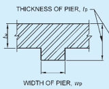
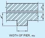
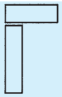
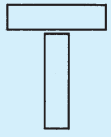
b) Pier — A thickened section forming integral part of a wall placed at intervals along the wall, to increase the stiffness of the wall or to carry a vertical concentrated load. Thickness of a pier is the overall thickness including the thickness of the wall or, when bonded into a leaf of a cavity wall, the thickness obtained
by treating that leaf as an independent wall (see Fig. 1)
c) Buttress — A pier of masonry built as an integral part of wall and projecting from either or both surfaces, decreasing in cross-sectional area from base to top.
FIG.1 DEFINITION OF PIER
2.4 Cross-Sectional Area of Masonry Unit — Net cross-sectional area of a masonry unit shall be taken as the gross cross-sectional area minus the area of cellular space. Gross cross-sectional area of cored units shall be determined to the outside of the coring but cross-sectional area of grooves shall not be deducted from the gross cross-sectional area to obtain the net cross-sectional area.
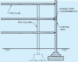
2.5 Curtain Wall — A non-load bearing wall subject to lateral loads. It may be laterally supported by vertical or horizontal structural members, where necessary (see Fig. 2).
NOTE — The figure is only illustrative to explain about the term curtain wall and is not intended to be an exhaustive provision.
FIG. 2 TYPICAL MASONRY CURTAIN WALL
2.6 Effective Height — The height of a wall or column, to be considered for calculating slenderness ratio.
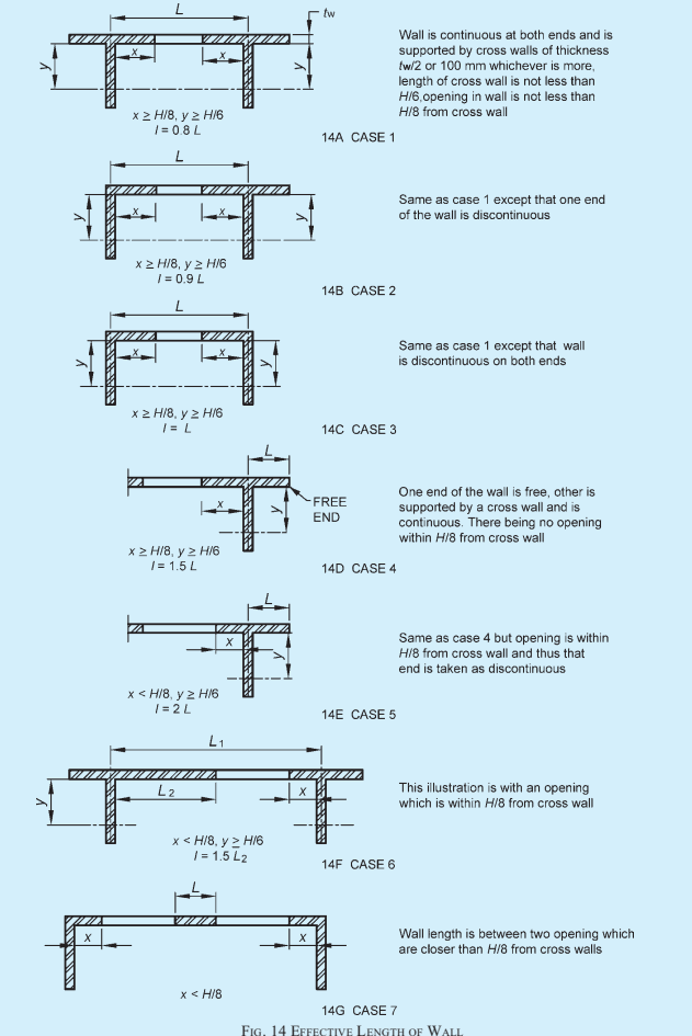
2.7 Effective Length — The length of a wall to be considered for calculating slenderness ratio.
2.8 Effective Thickness — The thickness of a wall or column to be considered for calculating slenderness ratio.
2.9 Hollow Unit — A masonry unit of which net cross-sectional area in any plane parallel to the bearing surface is less than 75 percent of its gross cross-sectional area measured in the same plane.
2.10 Grout — Mortar of pourable consistency.
2.11 Joint — A junction of masonry units, which can be classified as:
a) Bed joint — A horizontal mortar joint upon which masonry units are laid.
b) Cross joint — A vertical joint, normal to the face of the wall.
c) Wall joint — A vertical joint parallel to the face of the wall.
2.12 Leaf — Inner or outer section of a cavity wall.
2.13 Lateral Support — A support which enables a masonry element to resist lateral load and/or restrains lateral deflection of a masonry element at the point of support.
2.14 Load Bearing Wall — A wall designed to carry an imposed vertical load in addition to its own weight, together with any lateral load.
2.15 Masonry — An assemblage of masonry units properly bonded together with mortar.
2.16 Masonry Unit — Individual units which are bonded together with the help of mortar to form a masonry element such as wall, column, pier, buttress, etc.
2.17 Partition Wall — An interior non-load bearing wall, one storey or part storey in height.
2.18 Panel Wall — An exterior non-load bearing wall in framed construction, wholly supported at each storey but subjected to lateral loads.
2.19 Shear Wall — A wall designed to carry horizontal forces acting in its plane with or without vertical imposed loads.
2.20 Slenderness Ratio — Ratio of effective height or effective length to effective thickness of a masonry element.
2.21 Types of Walls
a) Cavity wall — A wall comprising two leaves,
each leaf being built of masonry units and separated by a cavity and tied together with metal ties or bonding units to ensure that the two leaves act as one structural unit, the space between the leaves being either left as continuous cavity or filled with a non-load bearing insulating and water-proofing material.
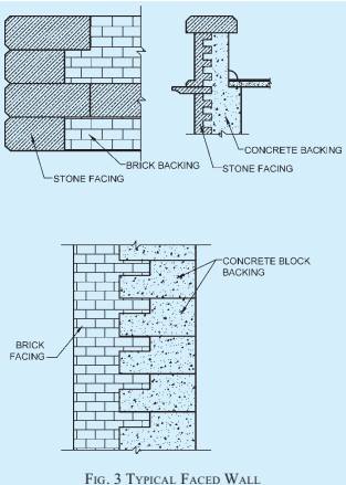
b) Faced wall — A wall in which facing and backing of two different materials are bonded together to ensure common action under load (see Fig. 3).
NOTE — To ensure monolithic action in faced walls, shear strength between the facing and the backing shall be provided by toothing, bonding or other means.
c) Veneered wall — A wall in which the facing is attached to the backing but not so bonded as to result in a common action under load.
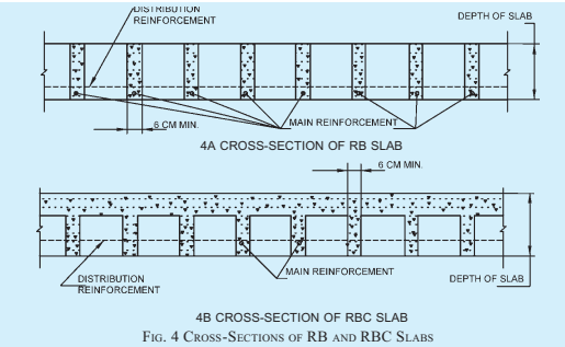
2.22 Reinforced Brick Slab (RB Slab) — Reinforced brick slab is particularly same as reinforced concrete slab in all its essential features except that brickwork is substituted partly for cement concrete. See Fig. 4A for details.
2.23 Reinforced Brick Concrete Slab (RBC Slab) — These are reinforced brick slab using concrete in the joints and on the top of bricks. See Fig. 4B for details.
3Materials
3.1 General
The materials used in masonry construction shall be in accordance with Part 5 ‘Building Materials’ of the Code. Storage of materials shall be in accordance with good practice [6-4(1)].
3.2 Masonry Units
Masonry units used in construction shall conform to accepted standards [6-4(2)].
3.2.1 Masonry units may be of the following types:
a) Common burnt clay building bricks,
b) Burnt clay fly ash building bricks,
c) Pulverized fuel ash lime bricks,
d) Stones (in regular sized units),
e) Sand-lime bricks,
f) Concrete blocks (solid and hollow),
g) Lime based blocks,
h) Burnt clay hollow blocks,
j) Gypsum partition blocks,
k) Autoclaved cellular concrete blocks,
m) Stabilized soil blocks, and
n) Concrete stone masonry blocks.
NOTES
1 Gypsum partition blocks are used only for construction of non-load bearing partition walls.
2 Use of other masonry units such as precast stone blocks, fly-ash-lime-gypsum bricks, stabilized soil blocks and other bricks/blocks not covered by the above specifications may also be permitted based on test results.
3.2.2 Masonry units that have been previously used shall not be reused in brickwork or blockwork construction, unless they have been thoroughly cleaned
and conform to this Section for similar new masonry units.
3.3 Mortar
Mortar for masonry shall conform to good practice [6-4(3)].
3.3.1 Minimum compressive strength for different grades of mortar on the basis of mix proportions as per 3.3.2 are given in Table 1.
Table 1Compressive Strength for Different Grades of Mortar (Clause 3.3.1)
Sl No.
Grade of Mortar
Minimum Compressive Strength at 28 Days N/mm²
(1)
(2)
(3)
i)
H1
10
ii)
H2
6.0
iii)
M1
5.0
iv)
M2
3.0
v)
M3
1.5
vi)
L1
0.7
vii)
L2
0.5
3.3.2 Mix proportions and compressive strengths of some of the commonly used mortars are given in Table 2.
3.4 Durability Criteria for Selection of Masonry Mortars
3.4.1 The selection of masonry mortars from durability considerations shall cover both the loading and exposure conditions of the masonry. The requirements for masonry mortar shall generally be as given in 3.4.2 to 3.4.6 (see also Table 1).
Table 2Mix Proportions and Strength of Mortars for Masonry (Clause 3.3.2)
Sl No.
Mix Proportions(By Mass)
Minimum Compressive Strength at 28 Days in N/mm ² (with Cement Compressive Strength at 28 Days, in N/mm ² , Between 33 and 43)
Minimum Compressive Strength of Cement : Sand Mortar at 28 Days in N/mm ² (with Cement Compressive Strength at 28 Days, in N/mm ² ≥ 43)
Cement
Lime
Lime - Pozzolana Mixture
Pozzolana
Sand
(1)
(2)
(3)
(4)
(5)
(6)
(7)
(8)
1
1
(1)/(4) C or B
0
0
3
10
—
2(a)
1
(1)/(4) C or B
0
0
4
7.5
—
2(b)
1
(1)/(2) C or B
0
0
4(1)/(2)
6
—
2(c)
1
0
0
0
4
6
7
3(a)
1
0
0
0
5
5
6
3(b)
1
1 C or B
0
0
6
3
—
3(c)
0
0
1(LP-40)
0
1(1)/(2)
3
—
4(a)
1
0
0
0
6
3
4
4(b)
1
2B
0
0
9
2
—
4(c)
0
1A
0
0
2
2
—
4(d)
0
1B
0
1
1
2
—
4(e)
0
1 C or B
0
2
4Design Considerations
4.1 General
Masonry structures gain stability from the support offered by cross walls, floors, roof and other elements such as piers and buttresses. Load bearing walls are structurally more efficient when the load is uniformly distributed and the structure is so planned that eccentricity of loading on the members is as small as possible. Avoidance of eccentric loading by providing adequate bearing of floor/roof on the walls providing adequate stiffness in slabs and avoiding fixity at the supports, etc, is especially important in load bearing walls in multistorey structures. These matters should receive careful consideration during the planning stage of masonry structures.
4.2Lateral Supports and Stability
4.2.1 Lateral Supports
Lateral supports for a masonry element such as load bearing wall or column are intended,
a) to limit slenderness of a masonry element so as to prevent or reduce possibility of buckling of the member due to vertical loads; and
b) to resist horizontal components of forces so as to ensure stability of a structure against overturning.
4.2.1.1 Lateral support may be in the vertical or horizontal direction, the former consisting of floor/roof bearing on the wall or properly anchored to the same and latter consisting of cross walls, piers or buttresses.
4.2.1.2 Requirements of 4.2.1(a) from consideration of slenderness may be deemed to have been met with, if
a) in case of a wall, where slenderness ratio is based on effective height, any of the following
constructions are provided:
RCC floor/roof slab (or beams and slab) irrespective of the direction of span, bears on the supported wall as well as cross walls, to the extent of at least 90 mm;
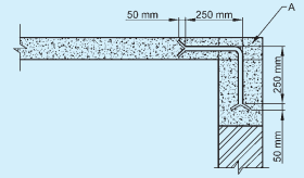
RCC floor/roof slab not bearing on the supported wall or cross wall is anchored to it with non-corrodible metal ties of 600 mm length and of section not less than 6 mm × 30 mm, and at intervals not exceeding 2 m, as shown in Fig. 5; and
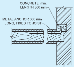
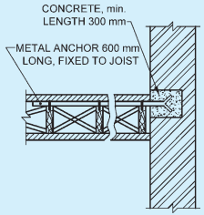
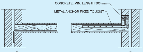
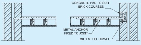
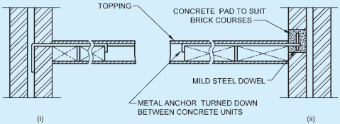
Timber floor/roof, anchored by non-corrodible metal ties of length 600 mm and of minimum section 6 mm × 30 mm, securely fastened to joists and built into walls as shown in Fig. 6 and Fig. 7. The anchors shall be provided in the direction of span of timber joists as well as in its perpendicular direction, at intervals of not more than 2 m in buildings up to two storeys and 1.25 m for buildings more than two storeys in height.
1 In case precast RCC units are used for floors and roofs, it is necessary to interconnect them and suitably anchor them to the cross walls so that they can transfer lateral forces to the cross walls.
2 In case of small houses of conventional designs, not exceeding two storeys in height, stiffening effect of partitions and cross walls is such that metal anchors are normally not necessary in case of timber floor/roof and precast RCC floor/roof units.
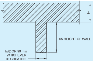
b) in case of a wall, when slenderness ratio is based on its effective length; a cross wall/pier/buttress of thickness equal to or more than half the thickness of the supported wall or 90 mm, whichever is more, and length equal to or more than one fifth of the height of wall, is built at right angle to the wall (see Fig. 8) and bonded to it according to provision of 4.2.2.2 (d);
c) in case of a column, an RCC or timber beam/RS joist/roof truss, is supported on the column.
A = Cement concrete only at places where anchors are provided (200 mm in width in the direction perpendicular to the plane of paper)
FIG. 5 ANCHORING OF RCC SLAB WITH MASONRY WALL (WHEN SLAB DOES NOT BEAR ON WALL)
6A JOISTS AT RIGHT ANGLE TO WALL
6B JOISTS PARALLEL TO WALL
FIG. 6 TYPICAL DETAILS FOR ANCHORAGE OF SOLID WALLS
7A TIMBER JOISTS AT RIGHT ANGLES TO WALL
7B TIMBER JOISTS PARALLEL TO WALL
7C PRECAST CONCRETE FLOOR UNITS PARALLEL TO WALL
FIG. 7 TYPICAL DETAILS FOR ANCHORAGE OF CAVITY WALLS
In this case, the column will not be deemed to be laterally supported in the direction at right angle to it; and
d) in case of a column, an RCC beam forming a part of beam and slab construction is supported on the column, and slab adequately bears on stiffening walls. This construction will provide lateral support to the column, in the direction of both horizontal axes.
FIG. 8 MINIMUM DIMENSION FOR MASONRY WALL OR BUTTRESS EFFECTIVE LATERAL SUPPORT
4.2.2 Stability
A wall or column subjected to vertical and lateral loads may be considered to be provided with adequate lateral support from consideration of stability, if the construction providing the support is capable of resisting some of the following forces:
a) Simple static reactions at the point of lateral support to all the lateral loads; plus
b) 2.5 percent of the total vertical load that the wall or column is designed to carry at the point of lateral support.
4.2.2.1 For the purpose specified in 4.2.2, if the lateral supports are in the vertical direction, these should meet the requirements given in 4.2.1.2 (a) and should also be capable of acting as horizontal girders duly anchored to the cross wall so as to transmit the lateral loads to the foundations without exceeding the permissible stresses in the cross walls.
4.2.2.2 In case of load bearing buildings up to four storeys, stability requirements of 4.2.2 may be deemed to have been met with, if
a) height to width ratio of building does not exceed 2;
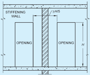
b) cross walls acting as stiffening walls continuous from outer wall to outer wall or outer wall to a load bearing inner wall, and of thickness and spacings as given in Table 3 are provided. If stiffening wall or walls that are in a line, are interrupted by openings, length of solid wall
or walls in the zone of the wall that is to be stiffened shall be at least one-fifth of height of the opening as shown in Fig. 9;
c) floors and roof either bear on cross walls or are anchored to those walls as in 4.2.1.2 such that all lateral loads are safely transmitted to those walls and through them to the foundation; and
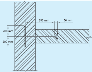
d) cross walls are built jointly with the bearing walls and are jointly mortared, or the two interconnected by toothing. Alternatively, cross walls may be anchored to walls to be supported by ties of non-corrodible metal of minimum section 6 mm×35 mm and length 600 mm with ends bend at least 50 mm; maximum vertical spacing of ties being 1.2 m (see Fig. 10).
4.2.2.3 In case of halls exceeding 8.0 m in length, safety and adequacy of lateral supports shall always be checked by structural analysis.
Table 3Thickness and Spacing of Stiffening Walls [Clause 4.2.2.2(b)]
Sl No.
Thickness of Load Bearing Wall to be Stiffened mm
Height ¹⁾ of Storey Not to Exceed m
Stiffening Wall ¹⁾
Thickness not Less than
Maximum Spacing m
1 to 3 Storeys mm (4)
4 Storeys mm (5)
(1)
(2)
(3)
(6)
4.6Slenderness Ratio
4.6.1 Walls
For a wall, slenderness ratio shall be effective height divided by effective thickness or, effective length divided by the effective thickness, whichever is less. In case of a load bearing wall, slenderness ratio shall not exceed that given in Table 8. To reduce the slenderness ratio one and a half brick thick wall shall be up to ground level.
FIG. 14 EFFECTIVE LENGTH OF WALL
Sl No.
Number of Storeys
Maximum Slenderness Ratio
Using Portland Cement or Portland Pozzolana Cement in Mortar
Using Lime Mortar
(1)
(2)
(3)
(4)
i)
Not exceeding 2
27
20
ii)
Exceeding 2
27
13
4.6.2 Columns
For a column, slenderness ratio shall be taken to be the greater of the ratios of effective heights to the respective effective thickness, in the two principal directions. Slenderness ratio for a load bearing column shall not exceed 12.
4.7 Eccentricity
Eccentricity of vertical loading at a particular junction in a masonry wall shall depend on factors, such as extent of bearing, magnitude of loads, stiffness of slab or beam, fixity at the support and constructional details at junctions. No exact calculations are possible to make accurate assessment of eccentricity. Extent of eccentricity under any particular circumstances has, therefore, to be decided according to the best judgment of the designer. Some guidelines for assessment of eccentricity are given in Annex A.
4.3Effective Height
4.3.1 Wall
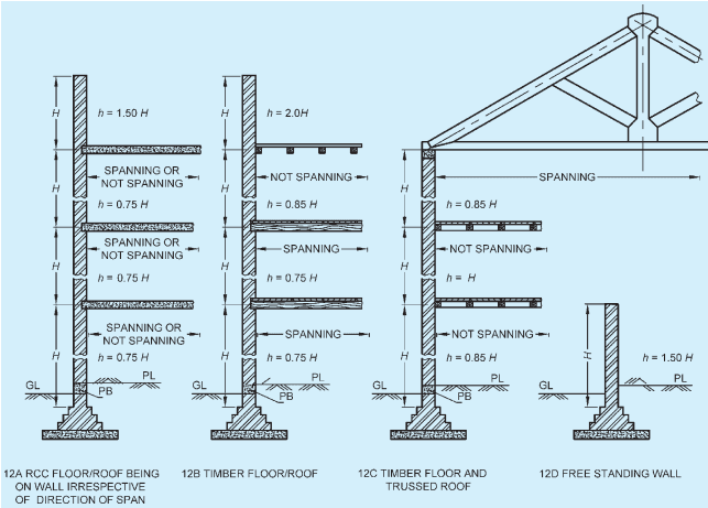
Effective height of a wall shall be taken as shown in Table 5 (see Fig. 12).
NOTE — A roof truss or beam supported on a column meeting the requirements of 4.2.2.1 is deemed to provide lateral support to the column only in the direction of the beam/truss.
Table 5Effective Height of Walls (Clause 4.3.1)
Sl No.(1)
Condition of Support(2)
Effective Height(3)
i) Lateral as well as rotational restraint (that is, full restraint) at top and bottom. For example, when the floor/roof spans on the walls so that reaction to load of floor/roof is provided by the walls, or when an RCC floor/roof has bearing on the wall (minimum 90 mm), irrespective of the direction of the span foundation footings of a wall give lateral as well as rotational restraint 0.75 H
ii) Lateral as well as rotational restraint (that is, full restraint) at one end and only lateral restraint (that is, partial restraint) at the other. For example, RCC floor/roof at one end spanning or adequately bearing on the wall and timber floor/roof not spanning on wall, but adequately anchored to it, on the other end 0.85 H
iii) Lateral restraint, without rotational restraint (that is, partial restraint) on both ends. For example, timber floor/roof, not spanning on the wall but adequately anchored to it on both ends of the wall, that is, top and bottom 1.00 H
iv) Lateral restraint as well as rotational restraint (that is, full restraint) at bottom but have no restraint at the top. For example, parapet walls with RCC roof having adequate bearing on the lower wall, or a compound wall with proper foundation on the soil. 1.50 H
1 H is the height of wall between centres of support in case of RCC slabs and timber floors. In case of footings or foundation block, height (H) is measured from top of footing or foundation block. In case of roof truss, height (H) is measured up to bottom of the tie beam. In case of beam and slab construction, height should be measured from centre of bottom slab to centre of top beam. All these cases are illustrated by means of examples shown in Fig. 12.
2 For working out effective height, it is assumed that concrete DPC, when properly bonded with masonry, does not cause discontinuity in the wall.
3 Where membrane type damp-proof course or termite shield causes a discontinuity in bond, the effective height of wall may be taken to be greater of the two values calculated as follows :
a) Consider H from top of footing ignoring DPC and take effective height as 0.75H.
b) Consider H from top of DPC and take effective height as 0.85 H.
4 When assessing effective height of walls, floors not adequately anchored to walls shall not be considered as providing lateral support to such walls.
5 When thickness of a wall bonded to a pier is at least two-thirds of the thickness of the pier measured in the same direction, the wall and pier may be deemed to act as one structural element.
NOTE — If plinth band (PB) is equal to or more than 150 mm, height can be taken from above the plinth band.
FIG. 12 EFFECTIVE HEIGHT OF WALL
4.3.2 Column
In case of a column, effective height shall be taken as actual height for the direction it is laterally supported and as twice the actual height for the direction it is not laterally supported (see Fig. 13).
1 A roof truss or beam supported on a column meeting the requirements of 4.2.2.1 is deemed to provide lateral support to the column only in the direction of the beam/truss.
2 When floor or roof consisting of RCC beams and slabs is supported on columns, the columns would be deemed to be laterally supported in both directions.
4.3.3 Openings in Walls
When openings occur in a wall such that masonry between the openings is by definition a column, effective height of masonry between the openings shall be reckoned as follows:
a) When wall has full restraint at the top:
Effective height for the direction
perpendicular to plane of wall equals 0.75H plus 0.25H₁, where H is the distance between supports and H₁ is the height of the taller opening; and
Effective height for the direction parallel to the wall equals H, that is, the distance between the supports.
b) When wall has partial restraint at the top and bottom:
Effective height for the direction perpendicular to plane of wall equals H when height of neither opening exceeds 0.5H and it is equal to 2H when height of any opening exceeds 0.5H; and
Effective height for the direction parallel to the plane of the wall equals 2H.
4.5Effective Thickness
Effective thickness to be used for calculating slenderness ratio of a wall or column shall be obtained as in 4.5.1 to 4.5.5.
4.5.1 For solid walls, faced walls or columns, effective thickness shall be the actual thickness.
4.5.2 For solid walls adequately bonded into piers, buttresses, effective thickness for determining slenderness ratio based on effective height shall be the actual thickness of wall multiplied by stiffening coefficient as given in Table 7. No modification in effective thickness, however, shall be made when slenderness ratio is to be based on effective length of walls.
4.5.3 For solid walls or faced walls stiffened by cross
walls, appropriate stiffening coefficient may be determined from Table 7 on the assumption that the cross walls are equivalent to piers of width equal to the thickness of the cross wall and of thickness equal to three times the thickness of stiffened wall.
Sl No.
Ratio (Sp)/(wp)
Stiffening Coefficient
(tp)/(tw)=1
(tp)/(tw)=2
(tp)/(tw)=3 or more
(1)
(2)
(3)
(4)
(5)
i)
6
1.0
1.4
2.0
ii)
8
1.0
1.3
1.7
iii)
10
1.0
1.2
1.4
iv)
15
1.0
1.1
1.2
v)
20 or more
1.0
1.0
1.0
where Sp = centre-to-centre spacing of the pier or cross wall, tp = thickness of pier as defined in 2.1.3 (b) (see Fig. 1), tw = actual thickness of the wall proper (see Fig. 1), and wp = width of the pier in the direction of the wall or the actual thickness of the cross wall.NOTE — Linear interpolation between the values given in this table is permissible but not extrapolation outside the limits given.
4.5.4 For cavity walls with both leaves of uniform thickness throughout, effective thickness shall be taken as two-thirds of the sum of the actual thickness of the two leaves.
4.5.5 For cavity walls with one or both leaves adequately bonded into piers, buttresses or cross walls at intervals, the effective thickness of the cavity wall shall be two-thirds of the sum of the effective thickness of each of the two leaves; the effective thickness of each leaf being calculated using 4.5.1 or 4.5.2 as appropriate.
5Structural Design
5.1 General
The building as a whole shall be analysed by accepted principles of mechanics to ensure safe and proper functioning in service of its component parts in relation to the whole building. All component parts of the structure shall be capable of sustaining the most adverse combinations of loads, which the building may be reasonably expected to be subjected to during and after construction.
5.2Design Loads
Loads to be taken into consideration for designing masonry components of a structure are:
a) dead loads of walls, columns, floors and roofs;
b) imposed loads of floors and roof;
c) wind loads on walls and sloping roof; and
d) seismic forces.
NOTE — When a building is subjected to other loads, such as vibration from railways; machinery, etc, these should be taken into consideration accordingly to the best judgment of the
designer (see also Part 6 ‘Structural Design, Section 1 Loads, Forces and Effects’ of the Code).
5.2.1 The design loads and other forces to be taken for the design of masonry structures shall conform to Part 6 ‘Structural Design, Section 1 Loads, Forces and Effects’ of the Code.
NOTE — During construction, suitable measures shall be taken to ensure that masonry is not liable to damage or failure due to action of wind forces, back filling behind walls or temporary construction loads.
5.3Load Dispersion
5.3.1 General
The angle of dispersion of vertical load on walls shall be taken as not more than 30° from the vertical.
5.3.2 Arching Action
Account may also be taken of the arching action of well-bonded masonry walls supported on lintels and beams, in accordance with established practice. Increased axial stresses in the masonry associated with arching action in this way, shall not exceed the permissible stresses given in 5.4.
5.3.3 Lintels
Lintels that support masonry construction shall be designed to carry loads from masonry (allowing for arching and dispersion where applicable), and loads received from any other part of the structure. Length of bearing of lintel at each end shall not be less than 90 mm or one-tenth of the span, whichever is more, and area of the bearing shall be sufficient to ensure that stresses in the masonry (combination of wall stresses, stresses due to arching action and bearing stresses from the lintel) do not exceed the stresses permitted in 5.4 (see Annex C).
5.4Permissible Stresses
5.4.1 Permissible Compressive Stress
Permissible compressive stress in masonry shall be based on value of basic compressive stress ( fb ) as given in Table 9 and multiplying this value by factors known as stress reduction factor ( ks ), area reduction factor ( ka ) and shape modification factor ( kp ) as detailed in 5.4.1.1 to 5.4.1.3. Values of basic compressive stress given in Table 9 take into consideration crushing strength of masonry unit and grades of mortar, and hold good for values of slenderness ratio not exceeding 6, zero eccentricity and masonry unit having height to width ratio (as laid) equal to 0.75 or less.
Alternatively, basic compressive stress may be based on results of prism test given in Annex B on masonry made from masonry units and mortar to be actually used in a particular job.
NOTE — Linear interpolation between values is permissible.
Table 9 Basic Compressive Stresses for Masonry (After 28 days)(Clauses 5.4.1 and 6.3.1)
Sl No.
Mortar Type (Ref Table 1)
Basic Compressive Stresses, in N/mm ² , Corresponding to Masonry Units of which Height to Width Ratio does not Exceed 0.75 and Crushing Strength, in N/mm ² , is not Less than
3.5(3)
5.0(4)
7.5(5)
10(6)
12.5(7)
15(8)
17.5(9)
20(10)
25(11)
30(12)
35(13)
40(14)
i)
H1
0.35
0.50
0.75
1.00
1.16
1.31
1.45
1.59
1.91
2.21
2.5
3.05
ii)
H2
0.35
0.50
0.74
0.96
1.09
1.19
1.30
1.41
1.62
1.85
2.1
2.5
iii)
M1
0.35
0.50
0.74
0.96
1.06
1.13
1.20
1.27
1.47
1.69
1.9
2.2
iv)
M2
0.35
0.44
0.59
0.81
0.94
1.03
1.10
1.17
1.34
1.51
1.65
1.9
v)
M3
0.25
0.41
0.56
0.75
0.87
0.95
1.02
1.10
1.25
1.41
1.55
1.78
vi)
L1
0.25
0.36
0.53
0.67
0.76
0.83
0.90
0.97
1.11
1.26
1.4
1.06
vii)
L2
0.25
0.31
0.42
0.53
0.58
0.61
0.65
0.69
0.73
0.78
0.85
0.95
NOTES
1 The table is valid for slenderness ratio up to 6 and loading with zero eccentricity.
2 The values given for basic compressive stress are applicable only when the masonry is properly cured.
3 Linear interpolation is permissible for units having crushing strengths between those given in the table.
4 The permissible stress for random rubble masonry may be taken as 75 percent of the corresponding stress for coarsed walling of similar materials.
5 The strength of ashlar masonry (natural stone masonry of massive type with thin joints) is closely related to intrinsic strength of the stone and allowable working stress in excess of those given in the table may be allowed for such masonry at the discretion of the designer.
6 For calculation of basic compressive stress of stabilized soil block having thickness 100 mm or more, reference to specialist literature may be made.
7 If the work is inadequately supervised, strength should be reduced to three-fourth or less at the discretion of the designer.
5.4.1.1 Stress reduction factor
This factor, as given in Table 10, takes into consideration the slenderness ratio of the element and also the eccentricity of loading.
Table 10Stress Reduction Factor for Slenderness Ratio and Eccentricity (Clause 5.4.1.1)
Sl No.
Slenderness Ratio
Eccentricity of Loading Divided by the Thickness of the Member
0(3)
1/24(4)
1/12(5)
1/6(6)
1/4(7)
1/3(8)
i)
6
1.00
1.00
1.00
1.00
1.00
1.00
ii)
8
0.95
0.95
0.94
0.93
0.92
0.91
iii)
10
0.89
0.88
0.87
0.85
0.83
0.81
iv)
12
0.84
0.83
0.81
0.78
0.75
0.72
v)
14
0.78
0.76
0.74
0.70
0.66
0.66
vi)
16
0.73
0.71
0.68
0.63
0.58
0.53
vii)
18
0.67
0.64
0.61
0.55
0.49
0.43
viii)
20
0.62
0.59
0.55
0.48
0.41
0.34
ix)
22
0.56
0.52
0.48
0.40
0.32
0.24
x)
24
0.51
0.47
0.42
0.33
0.24
—
xi)
26
0.45
0.40
0.35
0.25
—
—
xii)
27
0.43
0.38
0.33
0.22
—
—
NOTES1 Linear interpolation between values is permitted.2 Where in special cases the eccentricity of loading lies between 1/3 and 1/2 of the thickness of the member, the stress reduction factor should vary linearly between unity and 0.20 for slenderness ratio of 6 and 20, respectively.3 Slenderness ratio of a member for sections within 1/8 of the height of the member above or below a lateral support may be taken to be 6.
5.4.1.2 Area reduction factor
This factor takes into consideration smallness of the sectional area of the element and is applicable when sectional area of the element is less than 0.2 m² . The factor ka = 0.7 + 1.5A , A being the area of section, in m² .
5.4.1.3 Shape modification factor
This factor takes into consideration the shape of the unit, that is, height to width ratio (as laid) and is given in Table 11. This factor is applicable for units for crushing strength up to 15 N/mm² .
Table 11Shape Modification Factor for Masonry Units (Clause 5.4.1.3)
Sl No.
Height to Width Ratio of Units (As Laid)
Shape Modification Factor ( kp ) for Units Having Crushing Strength N/mm2
Up to 5.0 (3)
7.5 (4)
10.0 (5)
15.0 (6)
i)
Up to 0.75
1.0
1.0
1.0
1.0
ii)
1.0
1.2
1.1
1.1
1.0
iii)
1.5
1.5
1.3
1.2
1.1
iv)
2.0 to 4.0
1.8
1.5
1.3
1.2
5.4.1.4 Increase in permissible compressive stresses allowed for eccentric vertical loads, lateral loads under certain conditions
In members subjected to eccentric and/or lateral loads, increase in permissible compressive stress is allowed as follows:
a) When resultant eccentricity ratio exceeds 1/24 but does not exceed 1/6, 25 percent increase in permissible compressive stress is allowed in design.
b) When resultant eccentricity ratio exceeds 1/6, 25 percent increase in permissible stress is allowed but the area of the section under tension shall be disregarded for computing the load carrying capacity of the member.
NOTE — When resultant eccentricity ratio of loading is 1/24 or less, compressive stress due to bending shall be ignored and only axial stress need to be computed for the purpose of design.
5.4.1.5 Increase in permissible compressive stress for walls subjected to concentrated loads
When a wall is subjected to a concentrated load (a load being taken to be concentrated when area of supporting wall equals or exceeds three times the bearing area), certain increase in permissible compressive stress may be allowed because of dispersal of the load. Since, according to the present state of art, there is diversity of views in regard to manner and extent of dispersal, design of walls subjected to concentrated loads may, therefore, be worked out as per the best judgment of the designer. Some guidelines in this regard are given in Annex C.
5.4.2 Permissible Tensile Stress
As a general rule, design of masonry shall be based on the assumption that masonry is not capable of taking any tension. However, in case of lateral loads normal to the plane of wall, which causes flexural tensile stress, as for example, panel, curtain partition and free standing walls, flexural tensile stresses as follows may be permitted in the design for masonry:
a) Grade M1 1) 0.07N / mm² for bending in the vertical direction where tension developed is normal to bed joints.
0.14N / mm² for bending in the longitudinal direction where tension developed is parallel to bed joints, provided crushing strength of masonry units is not less than 10N / mm².
b) Grade M2 1) 0.05 N/mm² for bending in the vertical direction where tension developed is normal to bed joints.
0.10 N/mm² for bending in the longitudinal direction where tension developed is parallel to bed joints, provided crushing strength of masonry units is not less than 7.5 N/mm².
1 No tensile stress is permitted in masonry in case of water-retaining structures in view of water in contact with masonry. Also no tensile stress is permitted in earth-retaining structures, in view of the possibility of presence of water at the back of such walls.
2 Allowable tensile stress in bending in the vertical direction may be increased to 0.1N / mm² for M1 mortar and 0.07N / mm² for M2 mortar in case of boundary walls/compound at the discretion of the designer, since there is not much risk to life and property in the event of failure of such walls.
5.4.3 Permissible Shear Stress
In case of walls built in mortar not leaner than Grade M1 (see Table 1) and resisting horizontal forces in the plane of the wall, permissible shear stress calculated on the area of bed joints, shall not exceed the value obtained by the formula given below, subject to a maximum of 0.5 N/mm² :
f s = 0. 1 + f d / 6
fd = compressive stress due to dead loads, in N/mm ² ; and
fs = permissible shear stress, in N / mm²
5.4.4 If there is tension in any part of a section of masonry, the area under tension shall be ignored while working out shear stress on the section.
6General Requirements
6.1 Methods of Construction
6.1.1 General
Construction of the following types of load bearing and non-load bearing masonry walls shall be carried out in accordance with good practice [6-4(4)]:
a) Brickwork,
b) Stone masonry,
c) Hollow concrete block masonry,
d) Gypsum partition blocks,
e) Autoclaved cellular concrete block masonry, and
f) Lightweight concrete block masonry.
6.1.2 Construction of Buildings in Seismic Zones
Special features of construction for earthquake resistant masonry buildings in Seismic Zones II, III, IV and V shall be applicable according to 8.
6.2 Minimum Thickness of Walls from Consideration other than Structural
Thickness of walls determined from consideration of strength and stability may not always be adequate in respect of other requirements, such as resistance to fire, thermal insulation, sound insulation and resistance to damp penetration for which reference may be made to the appropriate Parts/Sections of the Code, and thickness suitably increased, where found necessary.
6.3 Workmanship
6.3.1 General
Workmanship has considerable effect on strength of
masonry and bad workmanship may reduce the strength of brick masonry to as low as half the intended strength. The basic compressive stress values for masonry as given in Table 9 holds good for commercially obtainable standards of workmanship with reasonable degree of supervision.
6.3.2 Bedding of Masonry Units
Masonry units shall be laid on a full bed of mortar with frog, if any, upward such that cross-joints and wall joints are completely filled with mortar. Masonry units which are moved after initial placement shall be re-laid in fresh mortar, discarding the disturbed mortar.
6.3.3 Bond
Cross-joints in any course of one brick thick masonry wall shall be not less than one-fourth of a masonry unit in horizontal direction from the cross-joints in the course below. In masonry walls more than one brick in thickness, bonding through the thickness of wall shall be provided by either header units or by other equivalent means in accordance with good practice [6-4(5)].
6.3.4 Verticality and Alignment
All masonry shall be built true and plumb within the tolerances prescribed below; care shall be taken to keep the perpends properly aligned:
a) Deviation from vertical within a storey shall not exceed 6 mm per 3 m height.
b) Deviation in verticality in total height of any wall of a building more than one storey in height shall not exceed 12.5 mm.
c) Deviation from position shown on plan of any brickwork shall not exceed 12.5 mm.
d) Relative displacement between load bearing walls in adjacent storeys intended to be in vertical alignment shall not exceed 6 mm.
e) Deviation of bed-joint from horizontal in a length of 12 m shall not exceed 6 mm subject to a maximum deviation of 12 mm.
f) Deviation from the specified thickness of bed joints, cross-joints and perends shall not exceed one-fifth of the specified thickness.
NOTE — These tolerances have been specified from the point of view of their effect on the strength of masonry. The permissible stress recommended in 5.3 may be considered applicable only, if these tolerances are adhered to.
6.4 Joints to Control Deformation and Cracking
Special provision shall be made to control or isolate thermal and other movements so that damage to the fabric of the building is avoided and its structural sufficiency preserved. Design and installation of joints shall be done according to the appropriate
recommendations in accordance with good practice [6-4(6)].
6.5 Chases, Recesses and Holes
6.5.1 Chases, recesses and holes are permissible in masonry only if these do not impair strength and stability of the structure.
6.5.2 In masonry, designed by structural analysis, all chases, recesses and holes shall be considered in structural design and detailed in building plans.
6.5.3 When chases, recesses and holes have not been considered in structural design and are not shown in drawings, these may be provided, subject to the constraints and precautions specified in 6.5.3.1 to 6.5.3.10.
6.5.3.1 As far as possible, services should be planned with the help of vertical chases and use of horizontal chases should be avoided.
6.5.3.2 For load bearing walls, depth of vertical and horizontal chases shall not exceed one-third and one-sixth of the wall thickness, respectively.
6.5.3.3 Vertical chases shall not be closer than 2 m in any stretch of wall and shall not be located within 345 mm of an opening or within 230 mm of a cross wall that serves as a stiffening wall for stability. Width of a vertical chase shall not exceed thickness of wall in which it occurs.
6.5.3.4 When unavoidable horizontal chases of width not exceeding 60 mm in a wall having slenderness ratio not exceeding 15 may be provided. These shall be located in the upper or lower middle third height of wall at a distance not less than 600 mm from a lateral support. No horizontal chase shall exceed 1 m in length and there shall not be more than 2 chases in any one wall. Horizontal chases shall have minimum mutual separation distance of 500 mm. Sum of lengths of all chases and recesses in any horizontal plane shall not exceed one-fourth the length of the wall.
6.5.3.5 Holes for supporting put-logs of scaffolding shall be kept away from bearings of beams, lintels, and other concentrated loads. If unavoidable, stresses in the affected area shall be checked to ensure that these are within safe limits.
6.5.3.6 No chase, recess or hole shall be provided in any stretch of a masonry wall, the length of which is less than four times the thickness of wall, except when found safe by structural analysis.
6.5.3.7 Masonry directly above a recess or a hole, if wider than 300mm, shall be supported on a lintel. No lintel, however, is necessary in case of a circular recess or hole exceeding 300mm in diameter provided upper
half of the recess or hole is built as a semi-circular arch of adequate thickness and there is an adequate length of masonry on the sides of openings to resist the horizontal thrust.
6.5.3.8 As far as possible, chases, recesses and holes in masonry should be left (inserting sleeves, where necessary) at the time of construction of masonry so as to obviate subsequent cutting. If cutting is unavoidable, it should be done without damage to the surrounding or residual masonry. It is desirable to use such tools for cutting which depend upon rotary and not on heavy impact for cutting action.
6.5.3.9 No chase, recess or hole shall be provided in half-brick load bearing wall, excepting the minimum number of holes needed for scaffolding.
6.6 Corbelling
6.6.1 Where corbelling is required for the support of some structural element, maximum projection of masonry unit should not exceed one-half of the height of the unit or one-half of the built-in part of the unit and the maximum horizontal projection of the corbel should not exceed one-third of the wall thickness.
6.6.2 The load per unit length on a corbel shall not be greater than half of the load per unit length on the wall above the corbel. The load on the wall above the corbel, together with four times the load on the corbel, shall not cause the average stress in the supporting wall or leaf to exceed the permissible stresses given in 5.4.
6.6.3 It is preferable to adopt header courses in the corbelled portion of masonry from considerations of economy and stability.
5.5Design Thickness/Cross-Section
5.5.1 Walls and Columns Subjected to Vertical Loads
Walls and columns bearing vertical loads shall be designed on the basis of permissible compressive stress. Design consists in determining thickness in case of walls and section in case of columns in relation to strength of masonry units and grade of mortar to be used, taking into consideration various factors, such as slenderness ratio, eccentricity, area of section, workmanship, quality of supervision, etc, subject further to provisions of 5.5.1.1 to 5.5.1.4.
5.5.1.1 Solid walls
Thickness used for design calculation shall be the actual thickness of masonry computed as the sum of the average dimensions of the masonry units specified in the relevant standard, together with the specified joint thickness. In masonry with raked joints, thickness shall be reduced by the depth of raking of joints for plastering/pointing.
5.5.1.2 Cavity walls
a) Thickness of each leaf of a cavity wall shall not be less than 75mm.
b) Where the outer leaf is half masonry unit in thickness, the uninterrupted height and length of this leaf shall be limited so as to avoid undue loosening of ties due to differential movements
between the two leaves. The outer leaf shall, therefore, be supported at least at every third storey or at every 10 m of height, whichever is less and at every 10 m or less along the length.
c) Where the load is carried by both leaves of a wall of a cavity construction, the permissible stress shall be based on the slenderness ratio derived from the effective thickness of the wall as given in 4.5.4 or 4.5.5. The eccentricity of the load shall be considered with respect to the centre of gravity of the cross-section of the wall.
d) Where the load is carried by one leaf only, the permissible stress shall be the greater of values calculated by the following two alternative methods:
The slenderness ratio is based on the effective thickness of the cavity wall as a whole as given in 4.5.4 or 4.5.5 and on the eccentricity of the load with respect to the centre of gravity of the cross-section of the whole wall (both leaves) (This is the same method as where the load is carried by both the leaves but the eccentricity will be more when the load is carried by one leaf only).
The slenderness ratio is based on the effective thickness of the loaded leaf only using 4.5.1 and 4.5.2, and the eccentricity of the load will also be with respect to the centre of gravity of the loaded leaf only.
In either alternative, only the actual thickness of the load bearing leaf shall be used in arriving at the cross-sectional area resisting the load (see 5.5.1.1).
5.5.1.3 Faced wall
The permissible load per length of wall shall be taken as the product of the total thickness of the wall and the permissible stress in the weaker of the two materials. The permissible stress shall be found by using the total thickness of the wall when calculating the slenderness ratio.
5.5.1.4 Veneered wall
The facing (veneer) shall be entirely ignored in calculations of strength and stability. For the purpose of determining the permissible stress in the backing, the slenderness ratio shall be based on the thickness of the backing alone.
5.5.2 Walls and Columns Mainly Subjected to Lateral Loads
5.5.2.1 Free standing walls
a) Free standing walls, subjected to wind pressure or seismic forces shall be designed on the basis of permissible tensile stress in masonry or stability as in 4.2.2.4. However, in seismic Zones II, free-standing walls may be apportioned without making any design calculations with the help of Table 12 provided the mortar used is of grade not leaner than M1.
b) If there is a horizontal damp-proof course near the base of the wall, that is, not capable of developing tension vertically, the minimum wall thickness should be the greater of that calculated from either,
the appropriate height to thickness ratio given in Table 12 reduced by 25 percent, reckoning the height from the level of the damp-proof course; or
the appropriate height to thickness ratio given in Table 12 reckoning the height from the lower level at which the wall is restrained laterally.
Table 12Height to Thickness Ratio of Free Standing Walls Related to Wind Speed [Clause 5.5.2.1(a) and (b)]
Sl No.
Design Wind Pressure N/mm2
Height to Thickness Ratio
(1)
(2)
(3)
i)
Up to 285
10
ii)
575
7
iii)
860
5
iv)
1 150
4
NOTES
1 For intermediate values, linear interpolation is permissible.
2 Height is to be reckoned from 150mm below ground level or top of footing/foundation block, whichever is higher, and up to the top edge of the wall.
3 The thickness should be measured including the thickness of the plaster.
5.5.2.2 Retaining walls
Normally masonry of retaining walls shall be designed on the basis of zero-tension, and permissible compressive stress. However, in case of retaining walls for supporting horizontal thrust from dry materials, retaining walls may be designed on the basis of permissible tensile stress at the discretion of the designers.
5.5.3 Walls and Columns Subjected to Vertical as well as Lateral Loads
For walls and columns, stress worked out separately
for vertical loads as in 5.5.1 and lateral loads as in 5.5.2 shall be combined and elements designed on the basis of permissible stress.
5.5.4 Walls Subjected to In-Plane Bending and Vertical Loads (Shear Walls)
Walls subjected to in-plane bending and vertical loads, that is, shear walls shall be designed on the basis of no tension with permissible shear stress and permissible compressive stress.
5.5.5 Non-Load Bearing Walls
Non-load bearing walls, such as panel walls, curtain walls and partition walls which are mainly subjected to lateral loads, according to present state of art, are not capable of precise design and only approximate methods based on some tests are available. Guidelines for approximate design of these walls are given in Annex D.
8.2General Principles
The general principles given in 8.2.1 to 8.2.9 shall be observed in construction of earthquake resistant buildings.
8.2.1 Lightness
Since the earthquake force is a function of mass, the weight of the building shall be as minimum as possible, consistent with structural safety and functional requirements. Roofs and upper storeys of buildings, in particular, should be designed as light as possible.
8.2.2 Continuity of Construction
8.2.2.1 As far as possible, the parts of the building should be tied together in such a manner that the building acts as one unit.
8.2.2.2 For parts of buildings between separation or crumple sections to expansion joints, floor slabs shall be continuous throughout as far as possible. Concrete slabs shall be rigidly connected or integrally cast with the support beams.
8.2.2.3 Additions to the structures shall be accompanied by the provision of separation or crumple sections between the new and the existing structures as far as possible, unless positive measures are taken to establish continuity between the existing and the new construction.
8.2.2.4 Alteration to the building structure shall be done by maintaining its structural stability by ensuring proper load path.
8.2.3 Projecting and Suspended Parts
8.2.3.1 Projecting parts shall be avoided as far as possible. If the projecting parts cannot be avoided, they shall be properly reinforced and firmly tied to the main structure, and their design shall be in accordance with good practice [6-4(8)].
8.2.3.2 Ceiling plaster shall preferably be avoided. When it is unavoidable, the plaster shall be as thin as possible.
8.2.3.3 Suspended ceiling shall be avoided as far as possible. Where provided they shall be light, adequately framed and secured to which electrical fixtures shall be fully secured.
8.2.4 Building Configuration
8.2.4.1 In order to minimise torsion and stress concentration, provisions given in 8.2.4.2 to 8.2.4.4 should be complied with as relevant.
8.2.4.2 The building should have a simple rectangular plan and be symmetrical both with respect to mass and rigidity so that the centre of mass and rigidity of the building coincide with each other in which case no separation sections other than expansion joints are necessary. For provision of expansion joints reference may be made to good practice [6-4(6)].
8.2.4.3 If symmetry of the structure is not possible in plan, elevation or mass, provision shall be made for torsional and other effects due to earthquake forces in the structural design or the parts of different rigidities may be separated through crumple sections. The length of such building between separation sections shall not preferably exceed three times the width.
NOTE — As an alternative to separation section to reduce torsional moments, the centre of rigidity of the building may be brought close or coincident to the centre of mass by adjusting the locations and/or sizes of columns and walls.
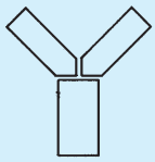
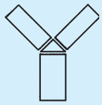
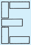
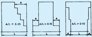
8.2.4.4 Buildings having plans with shapes like L, T, E and Y shall preferably be separated into rectangular parts by providing separation sections at appropriate places. Typical examples are shown in Fig. 15.
NOTES
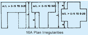
1 The buildings with small lengths of projections forming L, T, E or Y shapes need not be provided with separation section. In each cases the length of the projection may not exceed 15 to 20 percent of the total dimension of the building in the direction of the projection (see Fig. 16).
2 For buildings with minor asymmetry in plan and elevation, separation sections may be omitted.
8.2.5 Strength in Various Directions
The structure shall be designed to have adequate strength against earthquake effects along both the horizontal axes. The design shall also be safe considering the reversible nature of earthquake forces.
8.2.6 Foundations
The structure shall not be founded on such soils which shall subside or liquefy during an earthquake, resulting in large differential settlements (see also 8.3.3.3).
8.2.7 Ductility
The main structural elements and their connection shall be designed to have a ductile failure. This shall enable the structure to absorb energy during earthquakes to avoid sudden collapse of the structure. Providing reinforcing steel in masonry at critical sections, as specified in this Section shall not only increase strength and stability but also ductility. The details for achieving ductility in reinforced concrete structures is given in good practice [6-4(11)].
L - SHAPE
T-SHAPE
Y-SHAPE
Y-SHAPE
E-SHAPE
FIG. 15 TYPICAL SHAPES OF BUILDING WITH SEPARATION SECTIONS
16B Vertical Irregularities
FIG. 16 PLAN AND VERTICAL IRREGULARITIES
8.2.8 Damage to Non-Structural Parts
Suitable details shall be worked out to connect the non-structural parts with the structural framing so that the deformation of the structural frame leads to minimum damage of the non-structural elements.
8.2.9 Fire Safety
Fire frequently follows an earthquake and therefore, buildings shall be constructed to make them fire resistant in accordance with the provisions of Part 4 ‘Fire and Life Safety’ of the Code for fire safety.
8.3Special Construction Features
8.3.1 Separation of Adjoining Structures
8.3.1.1 Separation of adjoining structures or parts of the same structure is required for structures having different total heights or storey heights and different dynamic characteristics. This is to avoid collision during an earthquake.
8.3.1.2 Minimum width of separation gaps as mentioned in 8.3.1.1, shall be as specified in Table 13. The design seismic coefficient to be used shall be in accordance with 5 of Part 6 'Structural Design, Section 1 Loads, Forces and Effects' of the Code.
8.3.1.3 Where separation is necessary, a complete separation of the parts shall be made except below the plinth level. The plinth beams, foundation beams and footings may be continuous. Where separation sections
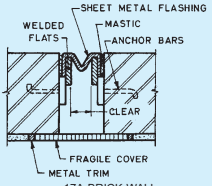
17A BRICK WALL
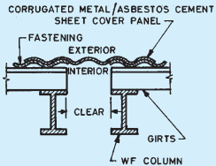
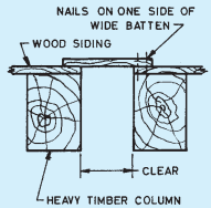
17C METAL SIDING INDUSTRIAL WORK
Table 13Gap Width for Adjoining Structures (Clause 8.3.1.2)
Sl.No.
Buildings Categories for Earthquake Resisting Features
Gap Width per Storey for Adjoining Masonry Building
mm
(1)
(2)
(3)
i)
Frames with shear walls
15
ii)
Category B¹⁾
10
iii)
Category C¹⁾
10
iv)
Category D¹⁾
15
v)
Category E¹⁾
20
¹⁾ See Table 14.
NOTE — Minimum total gap shall be 25 mm. For any other value of Ah the gap width shall be determined proportionately.
are provided in a long building, they shall take care of movement owing to temperature changes also.
8.3.2 Separation or Crumple Section
8.3.2.1 In case of framed construction, members shall be duplicated on either side of the separation or crumple section. As an alternative, in certain cases, such duplication may not be provided, if the portions on either side can act as cantilevers to take the weight of the building and other relevant loads.
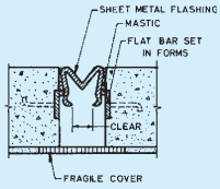
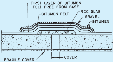
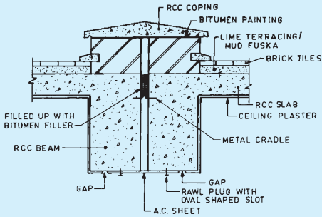
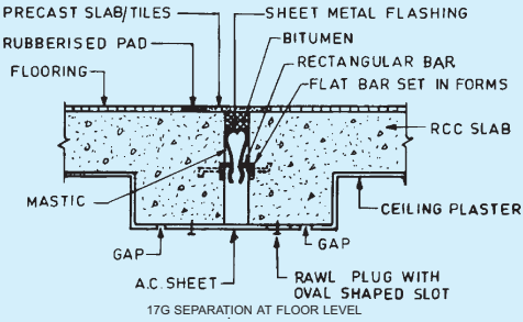
8.3.2.2 Typical details of separation and crumple sections are shown in Fig. 17. For other types of joint details, reference may be made to good practice [6-4(6)].
17B CONCRETE WALLS
17D WOOD SHEATHING INDUSTRIAL WORK
FIG. 17 TYPICAL DETAILS OF SEPARATION OR CRUMPLE SECTION (CONTINUED)
17E RCC SLAB ON ROOF SURFACE
17F SEPARATION JOINT DETAILS AT ROOF
NOTE — Fragile cover may consist of asbestos cement sheet, particle board and like.
FIG. 17 TYPICAL DETAILS OF SEPARATION OR CRUMPLE SECTION
8.3.3 Foundations
8.3.3.1 For the design of foundations, the provisions of Part 6 ‘Structural Design, Section 1 Loads, Forces and Effects’ and Section 2 ‘Soils and Foundation’ of the Code shall generally be followed.
8.3.3.2 The subgrade below the entire area of the building shall preferably be of the same type of the soil. Wherever this is not possible, a suitably located separation or crumple section shall be provided.
8.3.3.3 Loose fine sand, soft silt and expansive clays should be avoided. If unavoidable, the building shall rest either on a rigid raft foundation or on piles taken to a firm stratum. However, for light constructions the following measures may be taken to improve the soil on which the foundation of the building may rest:
a) Sand piling, and
b) Soil stabilization.
8.3.3.4 Isolated footings for columns
All the individual footings or pile caps where used in Type III Soft soils {Table 1 of good practice [6-4(9)]}, shall be connected by reinforced concrete ties at least in two directions approximately at right angles to each other. For buildings with no basement, the ties may be placed at or below the plinth level and for buildings with basement they may be placed at the level of basement floor. They shall need to be designed to carry the load of the panel walls also.
NOTE — The ties may not be necessary where structural floor connects the columns at or below the plinth level.
8.3.3.4.1 Where ties are used, their sections shall be designed to carry in tension as well as in compression, an axial load not less than the earthquake force in the direction the tie acting on the heavier of the columns connected, but the sections shall not be less than 200 mm × 200 mm with M20 concrete reinforced with 4 bars of 12 mm diameter plain mild steel bars or 10 mm diameter high strength deformed bars, one at each corner, bound by 8 mm diameter stirrups not more than 150 mm apart.
NOTE — In working out the buckling strength of ties, the lateral support provided by the soil may be taken into account. Calculations show that for such buried ties, lateral buckling is not a problem and the full section of the tie may be taken effective as a short column.
8.3.3.4.2 In the case of reinforced concrete slab, the thickness shall not be less than 1/50th of the clear distance between the footings, but not less than 100 mm in any case. It shall be reinforced with not less than 0.15 percent mild steel bars or 0.12 percent high strength deformed bars in each direction placed symmetrically at top and bottom.
8.3.4 Roofs and Floors
8.3.4.1 Flat roof or floor shall not preferably be made of tiles of ordinary bricks supported on steel, timber or reinforced concrete joists, nor they shall be of a type which in the event of an earthquake is likely to be loosened and parts or all of which may fall. If this type of construction cannot be avoided, the joists should be blocked at ends and bridged at intervals such that their spacing is not altered during an earthquake.
8.3.4.1.1 For pitched roofs, corrugated iron or asbestos sheets shall be used in preference to country, Allahabad or Mangalore tiles or other loose roofing units. All roofing materials shall be properly tied to the supporting members. Heavy roofing materials shall generally be avoided.
8.3.4.2 Pent roofs
8.3.4.2.1 All roof trusses shall be supported on reinforced concrete or reinforced brick band (see 8.6.4.3). The holding down bolts shall have adequate size and length as required for earthquake forces in accordance with 5 of Part 6 'Structural Design, Section 1 Loads, Forces and Effects' of the Code.
Where a trussed roof adjoins a masonry gable, the ends of the purlins shall be carried on and secured to a plate or bearer which shall be adequately bolted to reinforced concrete or reinforced brick band at the top of gable end masonry (see 8.6.4.4).
NOTE — Hipped roof in general have shown better structural behaviour during earthquakes than gable ended roofs.
8.3.4.2.2 At tie level all the trusses and the gable end shall be provided with diagonal braces in plan so as to transmit the lateral shear due to earthquake force to the gable walls acting as shear walls at the ends as specified in 8.6.4.
8.3.4.3 Jack arches
Jack arched roofs or floors, where used shall be provided with mild steel ties in all spans along with diagonal braces in plan to ensure diaphragms actions.
8.3.5 Staircases
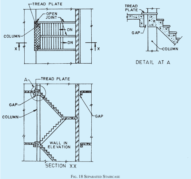
8.3.5.1 The inter-connection of the stairs with the adjacent floors should be appropriately treated by providing sliding joints at the stairs to eliminate their bracing effect on the floors. Large stair halls shall preferably be separated from the rest of the building by means of separation or crumple sections.
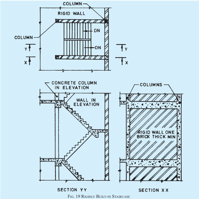
8.3.5.2 Three types of stair construction may be adopted as described below:
a) Separated staircases — One end of the staircase rests on a wall and the other end is carried by columns and beams which have no
connection with the floors. The gap at the vertical joints between the floor and the staircase may be covered either with a tread plate attached to one side of the joint and sliding on the other side, or covered with some appropriate material which could crumple or fracture during an earthquake without causing structural damage. The supporting members, columns or walls, are isolated from the surrounding floors by means of separation or crumple sections. A typical example is shown in Fig. 18.
as mentioned in respect of separated staircases, shall not be necessary.
The two walls mentioned above, enclosing the staircase, shall extend through the entire height of the stairs and to the building foundations.
c) Staircases with sliding joints — In case it is not possible to provide rigid walls around stair openings for built-in staircase or to adopt the separated staircases, the staircases shall have sliding joints so that they shall not act as diagonal bracing.
b) Built-in staircase — When stairs are built monolithically with floors, they can be protected against damage by providing rigid walls at the stair opening. An arrangement, in which the staircase is enclosed by two walls, is given in Fig. 19. In such cases, the joints,
8.4Types of Construction
8.4.1 The types of construction usually adopted in buildings are as follows:
a) Framed construction; and
b) Box type construction.
8.4.2 Framed Construction
This type of construction is suitable for multi-storied and industrial buildings as described in 8.4.2.1 and 8.4.2.2.
8.4.2.1 Vertical load carrying frame construction
This type of construction consists of frames with flexible (hinged) joints and bracing members. Steel multi-storied building or industrial frames and timber construction usually are of this type.
8.4.2.1.1 Such buildings shall be adequately strengthened against lateral forces by shear walls and/or other bracing systems in plan, elevation and sections such that earthquake forces shall be resisted by them in any direction.
8.4.2.2 Moment resistant frames with shear walls
The frames may be of reinforced concrete or steel with
semi-rigid or rigid joints. The walls are rigid capable of acting as shear walls and may be of reinforced concrete or of brickwork reinforced or unreinforced bounded by framing members through shear connectors.
8.4.2.2.1 The frame and wall combinations shall be designed to carry the total lateral force due to earthquake acting on the building. The frame acting alone shall be designed to resist at least 25 percent of the total lateral force.
8.4.2.2.2 The shear walls shall preferably be distributed evenly over the whole building. When concentrated at one location, forming what is called a rigid core in the building, the design shall be checked for torsional effects and the shear connection between the core and the floors conservatively designed for the total shear transfer.
8.4.2.2.3 The shear walls should extend from the foundation either to the top of the building or to a lesser height as required from design consideration. In design, the interaction between frame and the shear walls should be considered properly to satisfy compatibility and equilibrium conditions.
NOTE — Studies show that shear walls of height about 85 percent of total height of building are advantageous.
8.4.3 Box Type Construction
This type of construction consists of prefabricated or in-situ masonry, concrete or reinforced concrete walls along both the axes of the building. The walls support vertical loads and also act as shear walls for horizontal loads acting in any direction. All traditional masonry construction falls under this category. In prefabricated construction attention shall be paid to the connection between wall panels so that transfer of shear between them is ensured.
8.5Categories of Buildings
8.5.1 For the purpose of specifying the earthquake resisting features in masonry and wooden buildings, the buildings have been categorized in four categories B to E based on the seismic zone and the importance of the building I,
where
I = Importance factor applicable to the building {as per good practice [6-4(9)]}.
8.5.1.1 The building categories are given in Table 14.
Table 14Building Categories for Earthquake Resisting Features (Clause 8.5.1.1)
SI No.
Importance Factor
Seismic Zone
II(3)
III(4)
IV(5)
V(6)
i)
1.0
B
C
D
E
ii)
1.5
C
D
E
E
NOTE — Category A is now defunct as Seismic Zone I does not exist any more.
0
2
—
4(f)
0
0
1(LP-40)
0
1(3)/(4)
2
—
5(a)
1
0
0
0
7
2
3
5(b)
1
3B
0
0
12
1.5
—
5(c)
0
1A
0
0
3
1.5
—
5(d)
0
1B
0
2
1
1.5
—
5(e)
0
1 C or B
0
3
0
1.5
—
5(f)
0
0
1(LP-40)
0
2
1.5
—
6(a)
1
0
0
0
8
1
2
6(b)
0
1B
0
1
2
0.7
—
6(c)
0
1 C or B
0
2
1
0.7
—
6(d)
0
0
1(LP-40)
0
2(1)/(4)
0.7
—
6(e)
0
0
1(LP-20)
0
1(1)/(2)
0.7
—
7(a)
0
1B
0
0
3
0.5
—
7(b)
0
1 C or B
0
1
2
0.5
—
7(c)
0
0
1(LP-7)
0
1(1)/(2)
0.5
—
1 Sand for making mortar should be well graded. In case sand is not well graded, its proportions shall be reduced in order to achieve the minimum specified strength.
2 For mixes in Sl No. 1 and Sl No. 2, use of lime is not essential from consideration of strength as it does not result in increase in strength. However, its use is highly recommended since if improves workability.
3 For mixes in SI No. 3(a), 4(a), 5(a) and 6(a) either lime C or B to the extent of (1)/(4) part of cement (by mass) or some plasticizer should be added for improving workability.
4 For mixes in Sl No. 4(b) and 5(b), lime and sand should first be ground in mortar mill and then cement added to coarse stuff.
5 It is essential that mixes in Sl No. 4(c), 4(d), 5(d), 5(e), 6(b), 6(c), 7(a) and 7(b) are prepared by grinding in a mortar mill.
6 A, B and C denote eminently hydraulic lime, semi-hydraulic lime and fat lime respectively, as specified in appropriate standards listed in Part 5 'Building Materials' of the Code.
3.4.2 In the case of masonry exposed frequently to rains and where there is further protection by way of plastering or rendering or other finishes, the grade of mortar shall not be less than M3 but shall preferably be of grade M2. Where no protection is provided, the grade of mortar for external walls shall not be less than M2.
3.4.3 In the case of load bearing internal walls, the grade
of mortar shall preferably be M3 or more for high durability but in no case less than L1.
3.4.4 In the case of masonry in foundations laid below damp-proof course, the grades of mortar for use in masonry shall be as specified below:
a) Where soil has little moisture, masonry mortar of grade not less M3 shall be used.
b) Where soil is very damp, masonry mortar of grade preferably M2 or more shall be used. But in no case shall the grade of mortar be less than L1 and M3; and
c) Where soil is saturated with water, masonry mortar of grade M1 shall be used but in no case shall the grade of mortar be less than M2.
3.4.5 For masonry in buildings subject to vibration of machinery, the grade of mortar shall not be less than M1.
3.4.6 For parapets, where the height is greater than three times the thickness, the grade of masonry mortar used shall not be less than M1. In the case of low parapets, the grade of mortar shall be the same as that used in the wall masonry below.
3.4.7 The grade of mortar for bedding joints in masonry with large concrete blocks shall not be less than M1.
NOTE — For earthquake design consideration, recommended mortar mixes shall be as per Table 14.
i)
100
3.2
100
—
4.5
ii)
200
3.2
100
200
6.0
iii)
300
3.4
100
200
8.0
iv)
Above 300
5.0
100
200
8.0
¹⁾ Storey height and maximum spacings as given are centre-to-centre dimensions.
FIG. 9 OPENING IN STIFFENING WALL
FIG. 10 ANCHORING OF STIFFENING WALL WITH SUPPORT WALL
4.2.2.4 A trussed roofing may not provide lateral support unless special measures are adopted to brace and anchor the roofing. However, in case of residential and similar buildings of conventional design with trussed roofing having cross walls, it may be assumed that stability
requirements are met with by the cross walls and structural analysis for stability may be dispensed with.
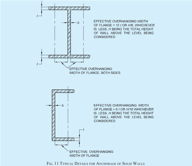
4.2.2.5 Capacity of a cross wall, also called shear wall, sometimes to take horizontal loads and consequently bending moments increases, when parts of bearing walls act as flanges to the cross wall. Maximum overhanging length of bearing wall which could effectively function as a flange should be taken as 12 t or H/6, whichever is less in case of T/I shaped walls, and 6 t or H/16, whichever is less in case of L/U shaped walls, where t is the thickness of bearing wall and H is the total height of wall above the level being considered, as shown in Fig. 11.
4.2.2.6 External walls of basement and plinth
In case of external walls of basement and plinth, stability requirements of 4.2.2 may be deemed to have been met with, if
a) bricks used in basement and plinth have a minimum crushing strength of 5N / mm² and mortar used in masonry is of Grade M1 or better;
b) clear height of ceiling in basement does not exceed 2.6 m;
c) walls are stiffened according to provisions of 4.2.2.1;
d) in the zone of action of soil pressure on basement walls, traffic load excluding any surcharge due to adjoining buildings does not exceed 5 kN/m² and terrain does not rise; and
e) minimum thickness of basement walls is in accordance with Table 4. However, if percentage opening in the basement wall for purposes like ventilation are more than 25 percent, then stability analysis/check need to be performed particularly for resistance to seismic loads.
NOTE — In case there is surcharge on basement walls from adjoining buildings, thickness of basement walls shall be based on structural analysis.
Table 4Minimum Thickness of Basement Walls [Clause 4.2.2.6(e)]
Sl No.
Height of the Ground Above Basement Floor Level
Minimum Nominal Thickness of Basement Wall
Wall Loading (Permanent Load) Less than 50 kN/m
Wall Loading (Permanent Load) More than 50 kN/m
(1)
(2)
(3)
mm(4)
i)
Up to 1.4 m
Up to 1.75 m
300
ii)
Up to 2 m
Up to 2.5 m
400
4.2.2.7 Walls mainly subjected to lateral loads
a) Free standing wall — A free standing wall such as compound wall or parapet wall is acted upon by wind force which tends to overturn it. This tendency to over-turning is resisted by gravity force due to self-weight of wall, and also by flexural moment of resistance on account of tensile strength of masonry. Free standing walls shall thus be designed as in 5.5.2.1. If mortar used for masonry cannot be relied upon for taking flexural tension (see 5.4.2), stability of free standing wall shall be ensured such that stability moment of wall due to self-weight equals or exceeds 1.5 times the overturning moment.
b) Retaining wall — Stability for retaining walls shall normally be achieved through gravity action but flexural moment of resistance could also be taken advantage of under special circumstances at the discretion of the designer (see 5.4.2).
6.5.3.10 Chases, recesses or holes shall not be cut into walls made of hollow or perforated units, after the units have been incorporated in masonry.