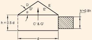
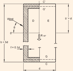
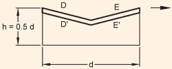
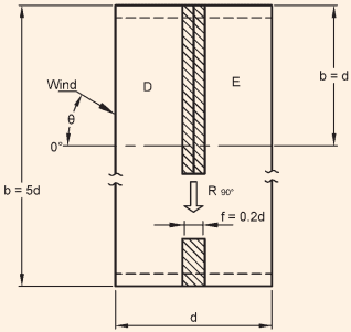
1.1 This Code (Part 6/Section 1) covers basic design loads to be assumed in the design of buildings. The imposed loads, wind loads, seismic forces, snow loads and other loads, which are specified herein, are minimum working loads which should be taken into consideration for purposes of design.
1.2 This Section does not take into consideration loads incidental to construction.
Part 6 Section 1Loads, Forces and Effects
BUREAU OF INDIAN STANDARDS
FOREWORD
... 3
1 SCOPE
... 7
2 DEAD LOAD
... 7
3 IMPOSED LOAD
... 7
4 WIND LOAD
... 18
5 SEISMIC FORCE
... 64
6 SNOW LOAD
... 92
7 SPECIAL LOADS
... 95
8 LOAD COMBINATIONS
...101
9 MULTI-HAZARD RISK IN VARIOUS DISTRICTS OF INDIA
...101
ANNEX A ILLUSTRATIVE EXAMPLE SHOWING REDUCTION OF UNIFORMLY DISTRIBUTED IMPOSED FLOOR LOADS IN MULTI-STOREYED BUILDINGS FOR DESIGN OF COLUMNS
...103
ANNEX B NOTATIONS
...104
ANNEX C BASIC WIND SPEED AT 10 m HEIGHT FOR SOME IMPORTANT CITIES/TOWNS
...105
ANNEX D CHANGES IN TERRAIN CATEGORIES
...106
ANNEX E EFFECT OF A CLIFF OR ESCARPMENT ON EQUIVALENT HEIGHT ABOVE GROUND (K₃ FACTOR)
...108
ANNEX F WIND FORCE ON CIRCULAR SECTIONS
...111
ANNEX G SYMBOLS
...112
ANNEX H MSK 1964 INTENSITY SCALE
...113
ANNEX J SIMPLIFIED PROCEDURE FOR EVALUATION OF LIQUEFACTION POTENTIAL
...115
ANNEX K LIST OF SOME IMPORTANT TOWNS AND THEIR SEISMIC ZONE FACTOR (Z)
...120
ANNEX L SHAPE COEFFICIENTS FOR MULTILEVEL ROOFS
...121
ANNEX M VIBRATIONS IN BUILDINGS
...122
ANNEX N BLAST LOAD
...123
ANNEX P SUMMARY OF DISTRICTS HAVING SUBSTANTIAL MULTI-HAZARD RISK AREAS
...130
LIST OF STANDARDS
...131
This Code (Part 6/Section 1) covers the various loads, forces and effects which are to be taken into account for structural design of buildings. The various loads that are covered under this Section are dead load, imposed load, wind load, seismic force, snow load, special loads and load combinations.
This Code was first published in 1970 and subsequently revised in 1983 and 2005. The first revision of this Section was modified in 1987 through Amendment No. 2 to the 1983 version of the Code to bring this Section in line with the latest revised loading code. Thereafter, in view of the revision of the important Indian Standard on earthquake resistant design of structure, that is, IS 1893 a need to revise this part was felt again. The second revision of 2005 was therefore formulated to take into account the revised standard, IS 1893 (Part 1): 2002 'Criteria for earthquake resistant design of structures: Part 1 General provision and buildings (fifth revision)' and to also incorporate latest information on additional loads, forces and effects as also the details regarding multi-hazard risk in various districts of India.
The significant changes incorporated in the second revision of 2005 included: the revision of the seismic zone map providing only four zones, instead of five, with erstwhile Zone I being merged into Zone II; changing of the values of seismic zone factors to reflect more realistic values of effective peak ground acceleration considering Maximum Considered Earthquake (MCE) and service life of structure in each seismic zone; specifying of response spectra for three types of founding strata, namely rock and hard soil, medium soil and soft soil; the revision of empirical expression for estimating the fundamental natural period Ta of multistoreyed buildings with regular moment resisting frames; adoption of the procedure of first calculating the actual force that may be experienced by the structure during the probable maximum earthquake, if it were to remain elastic, also bringing in the concept of response reduction due to ductile deformation or frictional energy dissipation in the cracks by introducing the 'response reduction factor' in place of the earlier performance factor; specifying a lower bound for the design base shear of buildings, based on empirical estimate of the fundamental natural period Ta; deletion of the soil-foundation system factor and instead, introduction of a clause to restrict the use of foundations vulnerable to differential settlements in severe seismic zones; revision of torsional eccentricity values upwards in view of serious damages observed in buildings with irregular plans; revision of modal combination rule in dynamic analysis of buildings; inclusion of a new clause on multi-hazard risk in various districts of India and a list of districts identified as multi-hazard prone districts; incorporation of latest amendments issued to IS 875; introduction of a clause on vibration in buildings for general guidance; and inclusion of reference to the Indian Standards on landslide control and design of retaining walls which were formulated after the first revision of the Section.
In this revision, following significant modifications/inclusions taking into account the recent developments, R & D efforts nationally and internationally, have been made:
Provisions on parapets and balustrades have been updated by including concentrated horizontal loads, wherever applicable, and modification in horizontal load per unit length. Also, new use areas covering appurtenances fixed to the structure have been included.
Aerodynamic roughness heights for individual terrain categories have been explicitly included, and are used to derive turbulence intensity and mean hourly wind speed profiles.
The previous classification of structures into B and C Classes has been deleted and accordingly the modification factor, k₂ is renamed as terrain roughness and height factor.
The values of k₂ factor corresponding to previous Class A type structure only, are retained in this Section.
An additional modification factor, k₄, termed as importance factor has been included for cyclonic regions.
Simple empirical expressions have been suggested for height variations of hourly mean wind speed and also turbulence intensity in different terrains.
Provisions to account for effects of directionality, area averaging and correlation of pressures on the design wind pressure have been included.
Guidelines to account for the wind induced interference for tall buildings and buildings less than 20m
have been included for use in preliminary design. It is however recommended to carry out detailed boundary layer wind tunnel tests/computational fluid dynamics (CFD) studies for final design of important structures.
In the gust factor method for evaluating along wind response, equations have been suggested for background factor, size reduction factor, energy ratio and length scale of turbulence.
A method for computing across wind response of tall buildings and lattice towers has been included.
The basic wind speed map of India has been updated based on the R&D studies in the country.
Provisions relating to design imposed load due to helipad have been included.
Provisions related to design imposed load due to fire tenders and emergency vehicle have been included.
Provisions relating to loads due to collision between vehicle and structural and non-structural elements in car parking and stilts.
Design spectra are defined for natural period up to 6 s.
Same design response spectra are specified for all buildings, irrespective of the material of construction.
Bases of various load combinations to be considered have been made consistent for earthquake effects, with those specified in the other codes.
Temporary structures are brought under the purview of this Section.
Importance factor provisions have been modified to introduce intermediate importance category of buildings, to acknowledge the density of occupancy of buildings.
A provision is introduced to ensure that all buildings are designed for at least a minimum lateral force.
Buildings with flat slabs are brought under the purview of this Section.
Additional clarity is brought in on how to handle different types of irregularity of structural system.
Effect of masonry infill walls has been included in analysis and design of frame buildings.
Method is introduced for arriving at the approximate natural period of buildings with basements, step back buildings and buildings on hill slopes.
Torsional provisions are simplified.
Provisions relating to simplified method of evaluation of liquefaction potential have been included in Annex J.
Provisions relating to design for blast loads have been included in Annex N.
There has been a growing awareness among the consultants, academicians, researchers and practice engineers for design and construction of wind sensitive structures. In order to augment the available limited good quality meteorological wind data and structural response data, it is necessary to conduct full scale measurements in the field. Thus as emphasized in the previous revision, all individuals and organizations responsible for putting up of tall structures are encouraged to provide instrumentation in their existing and new structures (transmission towers, chimneys, cooling towers, buildings, etc) at different elevations (at least at two levels) to continuously measure and monitor wind data. The instruments are required to collect data on wind direction, wind speed and structural response of the structure due to wind (with the help of accelerometer, strain gauges, etc). Such instrumentation in tall structures shall not in any way affect or alter the functional behaviour of such structures. The data so collected shall be very valuable in evolving more accurate wind loading of structures.
The information contained in this Section is largely based on the following Indian Standards:
IS 875 Code of practice for design loads (other than earthquake) for building and structure:
(Part 2): 1987 Imposed loads (second revision)
(Part 3): 2015 Wind loads (third revision)
(Part 4): 1987 Snow loads (second revision)
(Part 5): 1987 Special loads and load combinations (second revision)
IS 1893 (Part 1): 2016 Criteria for earthquake resistant design of structures: Part 1 General provisions and buildings (sixth revision)
This Section has to be read together with Sections 2 to 8 of Part 6 ‘Structural Design’ of this Code.
A special publication, SP 64 (S&T): 2001 ‘Explanatory Handbook on Indian Standard Code of Practice for Design Loads (Other than Earthquake) for Buildings and Structures IS 875 (Part 3): 1987’ is also available. This publication gives detailed background information on the provisions for wind loads and also the use of these provisions for arriving at the wind loads on buildings and structures while evaluating their structural safety.
However, in view of revision of IS 875 (Part 3) in 2015, applicability of this revised standard and this Section of the Code shall be taken as final in case of conflict of provisions with SP 64.
Reference may also be made to the Vulnerability Atlas of India, 2011 and Landslide Hazard Zonation Map of India, 2003 by Building Materials and Technology Promotion Council, Ministry of Urban Development and Poverty Alleviation, Government of India. The Vulnerability Atlas contains information pertaining to each State and Union Territory of India, on (a) seismic hazard map, (b) cyclone, and wind map, (c) flood prone area map, and (d) housing stock vulnerability table for each district indicating for each house type the level of risk to which it could be subjected. The Atlas can be used to identify areas in each district of the country which are prone to high risk from more than one hazard. The information will be useful in establishing the need of developing housing designs to resist the combination of such hazards.
In the formulation of this Section, inputs were also derived from the Heliport Manual, 1995 of the International Civil Aviation Organization.
For guidelines on risk reduction against tsunami for buildings and structures which are near-shore and on-shore within the expected run-up zone of the tsunami, reference may be made to the Indian Standard ‘Guidelines for Risk Reduction of Structures against Tsunami’ (under preparation). The standard deals also with the strategies for protection against tsunami and the design of structures located on coastal sites and in addition, includes special criteria for design of buildings that are to be used for vertical evacuation during a tsunami.
For criteria on structural safety of tall reinforced concrete (RC) buildings of heights greater than 45 m and less than 250 m, normally intended for use as residential, office and other commercial buildings, reference may be made to the Indian Standard ‘Criteria for Structural Safety of Tall Buildings’ (under preparation).
All standards, whether given herein above or cross-referred to in the main text of this Section, are subject to revision. The parties to agreement based on this Section are encouraged to investigate the possibility of applying the most recent editions of the standards.
For the purpose of deciding whether a particular requirement of this Section is complied with, the final value observed or calculated, expressing the result of a test or analysis, shall be rounded off in accordance with IS 2 : 1960 ‘Rules for rounding of numerical values (revised)’. The number of significant places retained in the rounded off value should be the same as that of the specified value in this Section.
Section 1 Loads, Forces and Effects
2Dead Load
2.1 Assessment of Dead Load
The dead load in a building shall comprise the weight of all walls, partitions, floors and roofs, and shall include the weights of all other permanent constructions (including built-in partitions, finishes, cladding and other similarly incorporated architectural and structural items, weight of fixed service equipment) in the building and shall conform to good practice [6-1(1)].
3.3Imposed Loads on Floors Due to Use and Occupancy
3.3.1 Imposed Loads
The imposed loads to be assumed in the design of buildings shall be the greatest loads that probably will be produced by the intended use or occupancy, but shall not be less than the equivalent minimum loads specified in Table 1 subject to any reductions permitted in 3.3.2.
Floors shall be investigated for both the uniformly distributed load (UDL) and the corresponding concentrated load specified in Table 1, and designed for the most adverse effects but they shall not be considered to act simultaneously. The concentrated loads specified in Table 1 may be assumed to act over an area of 0.3m× 0.3m. However, the concentrated loads need not be considered where the floors are capable of effective lateral distribution of this load.
All other structural elements shall be investigated for the effects of uniformly distributed loads on the floors specified in Table 1.
1 Where, in Table 1, no values are given for concentrated load, it may be assumed that the tabulated distributed load is adequate for design purposes.
2 The loads specified in Table 1 are equivalent uniformly distributed loads on the plan area and provide for normal effects of impact and acceleration. They do not take into consideration special concentrated loads and other loads.
3 Where the use of an area or floor is not provided in Table 1, the imposed load due to the use and occupancy of such an area shall be determined from the analysis of loads resulting from,
a) weight of the probable assembly of persons;
b) weight of the probable accumulation of equipment and furnishing;
c) weight of the probable storage materials; and
d) impact factor, if any.
4 While selecting a particular loading, the possible change in use or occupancy of the building should be kept in view. Designers should not necessarily select in every case the lower loading appropriate to the first occupancy. In doing this they might introduce considerable restrictions in the use of the building at a later date, and thereby reduce its utility.
5 The loads specified herein, which are based on estimations, may be considered as the characteristic loads for the purpose of limit state method of design till such time statistical data are established based on load surveys to be conducted in the country.
6 When an existing building is altered by an extension in height or area, all existing structural parts affected by the addition shall be strengthened where necessary, and all new structural parts shall be designed to meet the requirements for building hereafter erected.
7 The loads specified in the Section does not include loads incidental to construction. Therefore, close supervision during construction is essential to ensure that overloading of the building due to loads by way of stacking of building materials or use of equipment (for example, cranes and trucks) during construction or loads which may be induced by floor to floor propping in multi-storeyed construction, does not occur. However, if construction loads were of short duration, permissible increase in stresses in the case of working stress method or permissible decrease in load factors in limit state method, as applicable to relevant design codes, may be allowed for.
8 The loads in Table 1 are grouped together as applicable to buildings having separate principal occupancy or use. For a building with multiple occupancies, the loads appropriate to the occupancy with comparable use shall be chosen from other occupancies.
9 Regarding loading on lift machine rooms including storage space used for repairing lift machines, designers should go by the recommendations of lift manufacturers for the present. Regarding loading due to false ceiling, the same should be considered as imposed loads on the roof/floor to which it is fixed.
3.3.1.1 Load application
The uniformly distributed loads specified in Table 1 shall be applied as static loads over the entire floor area under consideration or a portion of the floor area, whichever arrangement produces critical effects on the structural elements as provided in respective design codes.
In the design of floors, the concentrated loads are
Table 1Imposed Floor Loads for Different Occupancies (Clause 3.3.1)
Sl No.
Occupancy Classification
Uniformly Distributed Load (UDL) kN/m2
Concentrated Load kN
(1)
(2)
(3)
(4)
i) Residential Buildings
a) Dwelling houses:
1) All rooms and kitchens
2.0
1.8
2) Toilets and bath rooms
2.0
—
3) Corridors, passages, staircases including fire escapes and store rooms
3.0
4.5
4) Balconies
3.0
1.5 per metre run concentrated at the outer edge
b) Dwelling units planned and executed in accordance with good practice [6-1(2)] only:
1) Habitable rooms, kitchens, and toilets and bath rooms
1.5
1.4
2) Corridors, passages and staircases including fire escapes
1.5
1.4
3) Balconies
3.0
1.5 per metre run concentrated at the outer edge
c) Hotels, hostels, boarding houses, lodging houses, dormitories and residential clubs:
1) Living rooms, bed rooms and dormitories
2.0
1.8
2) Kitchen and laundries
3.0
4.5
3) Billiards room and public lounges
3.0
2.7
4) Store rooms
5.0
4.5
5) Dining rooms, cafeterias and restaurants
4.0
2.7
6) Office rooms
2.5
2.7
7) Rooms for indoor games
3.0
1.8
8) Baths and toilets
2.0
—
9) Corridors, passages staircases including fire escapes and lobbies – as per the floor serviced (excluding stores and the like) but not less than
3.3.1.2 Loads due to light partitions
In office and other buildings, where actual loads due to light partitions cannot be assessed at the time of planning the floors and the supporting structural members shall be designed to carry, in addition to other loads, uniformly distributed loads per square metre of not less than 33.33 percent of weight per metre run of finished partitions, subject to a minimum of 1 kN/m² , provided total weight of partition walls per m² of the wall area does not exceed 1.5 kN/m² and the total weight per metre length is not greater than 4.0 kN.
3.3.2 Reduction in Imposed Loads on Floors
3.3.2.1 For members supporting floors
Except as provided for in 3.3.2.1(a), the following reductions in assumed total imposed loads on the floors may be made in designing columns, load bearing walls, piers, their supports and foundations:
Number of Floors (Including the Roof) to be Carried by Member Under Consideration
Reduction in Total Distributed Imposed Load on All Floors to be Carried by the Member Under Consideration Percent
1
0
2
10
3
20
4
30
5 to 10
40
Over 10
50
a) No reduction shall be made for any plant or machinery which is specifically allowed for, or for buildings for storage purposes, warehouses and garages. However, for other buildings, where the floor is designed for an imposed floor load of 5.0kN / m² or more, the reductions shown in 3.3.2.1 may be taken provided that the loading assumed is not less than it would have been, if all the floors had been designed for 5.0kN / m² with no reductions.
NOTE — In case, if the reduced load in the lower floor is lesser than the reduced load in the upper floor, then the reduced load of the upper floor will be adopted.
b) An example is given in Annex A illustrating the reduction of imposed loads in a multi-
storeyed building in the design of column members.
3.3.2.2 For beams in each floor level
Where a single span of beam, girder or truss supports not less than 50 m² of floor at one general level, the imposed floor load may be reduced in the design of the beams, girders or trusses by 5 percent for each 50 m² area supported subject to a maximum reduction of 25 percent. However, no reduction shall be made in any of the following types of loads:
a) Any superimposed moving load,
b) Any actual load due to machinery or similar concentrated loads,
c) The additional load in respect of partition walls; and
d) Any impact or vibration.
NOTE — The above reduction does not apply to beams, girders or trusses supporting roof loads.
3.3.3 Posting of Floor Capacities
Where a floor or part of a floor of a building has been designed to sustain a uniformly distributed load exceeding 3.0 kN/m² and in assembly, business, mercantile, industrial or storage buildings, a permanent notice in the form shown below indicating the actual uniformly distributed and/or concentrated loadings for which the floor has been structurally designed shall be posted in a conspicuous place in a position adjacent to such floor or on such part of a floor.
DESIGNED IMPOSED FLOOR LOADING
Distributed......kN/m2
Concentrated......kN
Label Indicating Designed Imposed Floor Loading
NOTES
1 The lettering of such notice shall be embossed or cast suitably on a tablet whose least dimension shall not be less than 0.25m and located not less than 1.5m above floor level with lettering of a minimum size of 25mm.
2 If a concentrated load or a bulk load has to occupy a definite position on the floor, the same could also be indicated in the table.
4Wind Load
NATIONAL BUILDING CODE OF INDIA 2016
4.1 General
4.1.1 This clause gives wind forces and their effects (static and dynamic) that should be taken into account when designing buildings, structures and components thereof.
4.1.2 Wind speeds vary randomly both in time and space and hence assessment of wind loads and response predictions are very important in the design of several buildings and structures. A large majority of structures met with in practice do not however, suffer wind induced oscillations and generally do not require to be examined for the dynamic effects of wind. For such normal, short and heavy structures, estimation of loads using static wind analysis has proved to be satisfactory. The details of this method involving important wind characteristics such as the basic wind speeds, terrain categories, modification factors, wind pressure and force coefficients, etc, are given in 4.4 and 4.5.
4.1.3 Nevertheless, there are various types of structures or their components such as some tall buildings which require investigation of wind induced oscillations. The influence of dynamic velocity fluctuations on the along wind loads (drag loads) for these structures shall be determined using Gust Factor Method, included in 4.8. A method for calculation of across wind response of tall buildings is included in 4.8.3.
4.1.4 This Section also applies to buildings or other structures during erection/construction and the same shall be considered carefully during various stages of erection/construction. In locations where the strongest winds and icing may occur simultaneously, loads on structural members, cables and ropes shall be calculated by assuming an ice covering based on climatic and local experience.
4.1.5 Wind is air in motion relative to the surface of the earth. The primary cause of wind is traced to earth's rotation and differences in terrestrial radiation. The radiation effects are primarily responsible for convection either upwards or downwards. The wind generally blows horizontal to the ground at high wind speeds. Since vertical components of atmospheric motion are relatively small, the term 'wind' denotes almost exclusively the horizontal wind; vertical winds are always identified as such. The wind speeds are assessed with the aid of anemometers or anemographs which are installed at meteorological observatories at heights generally varying from 10 to 30 m above ground.
4.1.6 Very strong winds (more than 80 km/h) are generally associated with cyclonic storms, thunderstorms, dust storms or vigorous monsoons. A feature of the cyclonic storms over the Indian area is that they rapidly weaken after crossing the coasts and move as depressions/lows inland. The influence of a severe storm after striking the coast does not; in general exceed about 60 km, though sometimes, it may extend even up to 120 km. Very short duration hurricanes of very high wind speeds called Kal Baisaki or Norwesters occur fairly frequently during summer months over North East India.
4.1.7 The wind speeds recorded at any locality are extremely variable and in addition to steady wind at any time, there are effects of gusts which may last for a few seconds. These gusts cause increase in air pressure but their effect on stability of the building may not be so important; often, gusts affect only part of the building and the increased local pressures may be more than balanced by a momentary reduction in the pressure elsewhere. Because of the inertia of the building, short period gusts may not cause any appreciable increase in stress in main components of the building although the walls, roof sheeting and individual cladding units (glass
panels) and their support-ing members such as purlins, sheeting rails and glazing bars may be more seriously affected. Gusts can also be extremely important for design of structures with high slenderness ratios.
4.1.8 The liability of a building to high wind pressures depends not only upon the geographical location and proximity of other obstructions to air flow but also upon the characteristics of the structure itself.
4.1.9 The effect of wind on the structure as a whole is determined by the combined action of external and internal pressures acting upon it. In all cases, the calculated wind loads act normal to the surface to which they apply.
4.1.10 The stability calculations as a whole shall be done considering the combined effect, as well as separate effects of imposed loads and wind loads on vertical surfaces, roofs and other part of the building above general roof level.
4.1.11 Buildings shall also be designed with due attention to the effects of wind on the comfort of people inside and outside the buildings.
NOTES
1 This Section does not apply to buildings or structures with unconventional shapes, unusual locations, and abnormal environmental conditions that have not been covered in this Code. Special investigations are necessary in such cases to establish wind loads and their effects. Wind tunnel studies may also be required in such situations.
2 In the case of tall structures with unsymmetrical geometry, the designs may have to be checked for torsional effects due to wind pressure.
3 The provisions given in good practice [6-1(4)] may be suitably referred by the design engineer/planner for reference.
4.2 Notations
The notations to be followed unless otherwise specified in relevant clauses under wind loads are given in Annex B.
4.3Terminology
4.3.1 For the purpose of wind loads, the definitions given below shall apply.
4.3.1.1 Angle of attack — An angle between the direction of wind and a reference axis of the structure.
4.3.1.2 Breadth — It means horizontal dimension of the building measured normal to the direction of wind.
4.3.1.3 Depth — It means the horizontal dimension of the building measured in the direction of the wind.
NOTE — Breadth and depth are dimensions measured in relation to the direction of wind, whereas length and width are dimensions related to the plan.
4.3.1.4 Developed height — It is the height of upward penetration of the velocity profile in a new
terrain. At large fetch lengths, such penetration reaches the gradient height, above which the wind speed may be taken to be constant. At lesser fetch lengths, a velocity profile of a smaller height but similar to that of the fully developed profile of that terrain category has to be taken, with the additional provision that the velocity at the top of this shorter profile equal to that of the un-penetrated earlier velocity profile at that height.
4.3.1.5 Effective frontal area — The projected area of the structure normal to the direction of wind.
4.3.1.6 Element of surface area — The area of surface over which the pressure coefficient is taken to be constant.
4.3.1.7 Force coefficient — A non-dimensional coefficient such that the total wind force on a body is the product of the force coefficient, the dynamic pressure of the incident design wind speed and the reference area over which the force is required.
NOTE — When the force is in the direction of the incident wind, the non-dimensional coefficient will be called as ‘drag coefficient’. When the force is perpendicular to the direction of incident wind, the non-dimensional coefficient will be called as ‘lift coefficient’.
4.3.1.8 Ground roughness — The nature of the earth's surface as influenced by small scale obstructions such as trees and buildings (as distinct from topography) is called ground roughness.
4.3.1.9 Gust — A positive or negative departure of wind speed from its mean value, lasting for not more than, say, 2 min over a specified interval of time.
4.3.1.10 Peak gust — A peak gust or peak gust speed is the wind speed associated with the maximum amplitude.
4.3.1.11 Fetch length — It is the distance measured along the wind from a boundary at which a change in the type of terrain occurs. When the changes in terrain types are encountered (such as, the boundary of a town or city, forest, etc), the wind profile changes in character but such changes are gradual and start at ground level, spreading or penetrating upwards with increasing fetch length.
4.3.1.12 Gradient height — It is the height above the mean ground level at which the gradient wind blows as a result of balance among pressure gradient force, Coriolis force and centrifugal force. For the purpose of this Section, the gradient height is taken as the height above the mean ground level, above which the variation of wind speed with height need not be considered.
4.3.1.13 Tall building — A building with a height more than or equal to 50 m or having a height to smaller
lateral dimension more than 6.
4.3.1.14 Mean ground level — The mean ground level is the average horizontal plane of the area enclosed by the boundaries of the structure.
4.3.1.15 Pressure coefficient — It is the ratio of the difference between the pressure acting at a point on the surface and the static pressure of the incident wind to the design wind pressure, where the static and design wind pressures are determined at the height of the point considered after taking into account the geographical location, terrain conditions and shielding effect. The pressure coefficient is also equal to [1-(Vp/Vz)²] , where Vp is the actual wind speed at any point on the structure at a height corresponding to that of Vz .
NOTE — Positive sign of the pressure coefficient indicates pressure acting towards the surface and negative sign indicates pressure acting away from the surface.
4.3.1.16 Return period — It is the number of years, reciprocal of which gives the probability of extreme wind exceeding a given wind speed in anyone year.
4.3.1.17 Shielding effect — Shielding effect or shielding refers to the condition where wind has to pass along some structure(s) or structural element(s) located on the upstream wind side, before meeting the structure or structural element under consideration. A factor called ‘shielding factor’ is used to account for such effects in estimating the force on the shielded structures.
4.3.1.18 Suction — It means pressure less than the atmospheric (static) pressure and is taken to act away from the surface.
4.3.1.19 Solidity ratio — It is equal to the effective area (projected area of all the individual elements) of a frame normal to the wind direction divided by the area enclosed by the boundary of the frame normal to the wind direction.
NOTE — Solidity ratio is to be calculated for individual frames.
4.3.1.20 Terrain category — It means the characteristics of the surface irregularities of an area which arise from natural or constructed features. The categories are numbered in increasing order of roughness.
4.3.1.21 Topography — The nature of the earth's surface as influenced by the hill and valley configurations.
4.3.1.22 Velocity profile — The variation of the horizontal component of the atmospheric wind speed at different heights above the mean ground level is termed as velocity profile.
3.4Imposed Loads on Roofs
3.4.1 Imposed Loads on Various Types of Roofs
On flat roofs, sloping roofs and curved roofs, the imposed loads due to use and occupancy of the buildings and the geometry of the types of roofs shall be as given in Table 2.
3.4.1.1 Roofs of buildings used for promenade or
Table 2 Imposed Loads on Various Types of Roofs(Clause 3.4.1)
Sl No.(1)
Type of Roof(2)
Imposed Load Measured on Plan Area(3)
Minimum Imposed Load Measured on Plan(4)
i)
Flat, sloping or curved roof with slopes up to and including 10°:
a) Access provided
1.5 kN/m²
3.75 kN uniformly distributed over any span of one metre width of the roof slab and 9 kN uniformly distributed over the span of any beam or truss or wall
b) Access not provided except for maintenance
0.75 kN/m²
1.9 kN uniformly distributed over any span of one metre width of the roof slab and 4.5 kN uniformly distributed over the span of any beam or truss or wall
ii)
Sloping roof with slope greater than 10°
For roof membrane sheets or purlins - 0.75 kN/m² less 0.02 kN/m² for every degree increase in slope over 10°
Subject to a minimum of 0.4 kN/m²
iii)
Curved roof with slope of line obtained by joining springing point to the crown with the horizontal, greater than 10°
(0.75 - 0.52 α²) kN/m² where α = h/l h = height of the highest point of the structure measured from its springing; and l = chord width of the roof if singly curved and shorter of the two sides if doubly curved.Alternatively, where structural analysis can be carried out for curved roofs of all slopes in a simple manner applying the laws of statistics, the curved roofs shall be divided into minimum 6 equal segments and for each segment imposed load shall be calculated appropriate to the slope of the chord of each segment as given in Sl No. (i) and (ii).
Subject to a minimum of 0.4 kN/m²
NOTES
1 The loads given above do not include loads due to snow, rain, dust collection, etc. The roof shall be designed for imposed loads given above or for snow/rain load, whichever is greater.
2 For special types of roofs with highly permeable and absorbent material, the contingency of roof material increasing in weight due to absorption of moisture shall be provided for.
incidental to assembly purposes shall be designed for the appropriate imposed floor loads given in Table 1 for the occupancy.
3.4.2 Concentrated Load on Roof Coverings
To provide for loads incidental to maintenance, unless otherwise specified by the Engineer-in-Charge, all roof coverings (other than glass or transparent sheets made of fibre glass) shall be capable of carrying an incidental load of 0.90 kN concentrated on an area of 1 250 mm ² so placed as to produce maximum stresses in the covering. The intensity of the concentrated load may be reduced with the approval of the Engineer-in-Charge, where it is ensured that the roof coverings would not be traversed without suitable aids. In any case, the roof coverings shall be capable of carrying the loads in accordance with 3.4.1, 3.4.3 and 3.4.4 and wind load.
3.4.3 Loads Due to Rain
On surfaces whose positioning, shape and drainage system are such as to make accumulation of rain water possible, loads due to such accumulation of water and the imposed loads for the roof as given in Table 2 shall
be considered separately and the more critical of the two shall be adopted in the design.
3.4.4 Dust Loads
In areas prone to settlement of dust on roofs (for example, steel plants, cement plants), provision for dust load equivalent to probable thickness of accumulation of dust may be made.
3.4.5 Loads on Members Supporting Roof Coverings
Every member of the supporting structure which is directly supporting the roof covering(s) shall be designed to carry the more severe of the following loads except as provided in 3.4.5.1:
a) The load transmitted to the members from the roof covering(s) in accordance with 3.4.1, 3.4.3 and 3.4.4; and
b) An incidental concentrated load of 0.90 kN concentrated over a length of 125 mm placed at the most critical positions on the member.
NOTE — Where it is ensured that the roofs would be traversed only with the aid of planks and ladders capable of distributing
the loads on them to two or more supporting members, the intensity of concentrated load indicated in 3.4.5 (b) may be reduced to 0.5 kN with the approval of the Engineer-in-Charge.
3.4.5.1 In case of sloping roofs with slope greater than 10°, members supporting the roof purlins, such as trusses, beams, girders, etc, may be designed for two-thirds of the imposed load on purlin or roofing sheets.
3.5 Imposed Horizontal Loads on Parapets, Balustrades and Other Appurtenances Fixed to Structure, and on Grandstands
3.5.1 Parapets, Parapet Walls, Balustrades and other Appurtenances Fixed to the Structure such as Grab Bars, Fixed Ladders and Guardrails in Stilt Parking
Parapets, parapet walls, balustrades and other appurtenances fixed to the structure such as grab bars, fixed ladders and guardrails in stilt parking, together with the members which give them structural support, shall be designed for the minimum loads given in Table 3. These are expressed as horizontal forces acting at handrail or coping level. These loads shall be considered to act vertically also but not simultaneously with the horizontal forces. The values given in Table 3 are minimum values and where values for actual loadings are available, they shall be used instead.
3.5.2 Grandstands and the Like
Grandstands, stadia, assembly platforms, reviewing stands and the like shall be designed to resist a horizontal force applied to seats of 0.35kN per linear metre along the line of seats and 0.15kN per linear metre perpendicular to the line of the seats. These loadings need not be applied simultaneously. Platforms without seats shall be designed to resist a minimum
horizontal force of 0.25kN / m² of plan area.
3.6Loading Effects Due to Impact and Vibration
The crane loads to be considered under imposed loads shall include the vertical loads, eccentricity effects induced by vertical loads, impact factors, lateral and longitudinal braking forces acting across and along the crane rails, respectively.
3.6.1 Impact Allowance for Lifts, Hoists and Machinery
The imposed loads specified in 3.3.1 shall be assumed to include adequate allowance for ordinary impact conditions. However, for structures carrying loads which induce impact or vibration, as far as possible, calculations shall be made for increase in the imposed load due to impact or vibration. In the absence of sufficient data for such calculation, the increase in the imposed loads shall be as follows:
Structures
Impact Allowance Percent Min
i)
For frames supporting lifts and hoists
100
ii)
For foundations, footings and piers supporting lifts and hoisting apparatus
40
iii)
For supporting structures and foundations for light machinery, shaft or motor units
20
iv)
For supporting structures and foundations for reciprocating machinery or power units
50
Table 3Horizontal Loads on Parapets, Parapet Walls and Balustrades (Clause 3.5.1)
Sl No.
Usage Area
Intensity of Horizontal Load kN/m Run
Concentrated load (For Each 3m length) kN
(1)
(2)
(3)
(4)
i)
Light access stairs, gangways and like, not more than 600 mm wide
0.25
—
ii)
Light access stairs, gangways and like, more than 600 mm wide; stairways, landings, balconies and parapet walls (private and part of dwellings)
0.35
—
iii)
a) All other stairways, landings and balconies and all parapets and handrails to roofs [except those subject to overcrowding covered under Sl No. (iv)]
0.75
0.89
b) Panel fillers
0.20
0.22
iv)
Parapets and balustrades:
a) In places of assembly, such as restaurants and bars, retail and public areas, not likely to be overcrowded
1.5
1.5
b) In places of assembly, such as retail areas, theatres, cinemas, bars, auditoria, shopping malls, discothèques, places of worship, likely to be overcrowded
3.0
1.5
v)
Grab bars
—
1.11
vi)
Fixed ladders
—
1.33
vii)
Guardrail systems and handrail assemblies
0.73
0.89
NOTE — In the case of guard parapets on a floor of multi-storeyed car park or crash barriers provided in certain buildings for fire escape, the value of imposed horizontal load (together with impact load) may be determined. For (vii), this load need not be considered for (a) one- and two-family dwellings, and (b) factory, industrial and storage occupancies, in areas that serve occupant load not greater than 22 kN.
3.6.2 Concentrated Imposed Loads with Impact and Vibration
Concentrated imposed loads with impact and vibration which may be due to installed machinery shall be considered and provided for in the design. The impact factor shall not be less than 20 percent which is the amount allowable for light machinery.
3.6.2.1 Provision shall also be made for carrying any concentrated equipment loads while the equipment is being installed or moved for servicing and repairing.
3.6.3 Impact Allowance for Crane Girders
For crane gantry girders and supporting columns, the impact allowances (given below) shall be deemed to cover all forces set up by vibration, shock from slipping of slings, kinetic action of acceleration, and retardation and impact of wheel loads:
Forces specified in (c) and (d) shall be considered as acting at the rail level and being appropriately transmitted to the supporting system. Gantry girders and their vertical supports shall be designed on the assumption that either of the horizontal forces in (c) and (d) may act at the same time as the vertical load.
NOTE — See good practice [6-1(3)] for classification (Class I to Class IV) of cranes.
3.6.3.1 Overloading factors in crane supporting structures
For all ladle cranes and charging cranes where there is possibility of overloading from production considerations, an overloading factor of 10 percent of the maximum wheel loading shall be taken.
3.6.4 Crane Load Combinations
In the absence of any specific indications, the load combinations shall be as indicated below.
Type of Load
Additional Load
a)
Vertical loads for electric overhead cranes
25 percent of maximum static loads for crane girders for all class of cranes
25 percent for columns supporting Class III and Class IV cranes
10 percent for columns supporting Class I and Class II cranes
No additional load for design of foundations
b)
Vertical loads for hand operated cranes
10 percent of maximum wheel loads for crane girders only
c)
Horizontal forces transverse to rails:
1) For electric overhead cranes with trolley having rigid mast for suspension of lifted weight (such as soaker crane, stripper crane, etc)
10 percent of weight of crab and the weight lifted by the cranes, acting on any one crane track rail, acting in either direction and equally distributed amongst all the wheels on one side of rail track
For frame analysis, this force, calculated as above, shall be applied on one side of the frame at a time in either direction
2) For all other electric overhead cranes and hand operated cranes
5 percent of weight of crab and the weight lifted by the cranes, acting on any one crane track rail, acting in either direction and equally distributed amongst the wheels on one side of rail track
For the frame analysis, the force, calculated as above, shall be applied on one side of the frame at a time in either direction
d)
Horizontal traction forces along the rails for overhead cranes, either electrically operated or hand operated
5 percent of all static wheel loads
3.6.4.1 Vertical loads
In an aisle, where more than one crane is in operation or has provision for more than one crane in future, the following load combinations shall be taken for vertical
loading:
a) Two adjacent cranes working in tandem with full load and with overloading according to 3.6.3.1; and
b) For long span gantries, where more than one crane can come in the span, the girder shall be designed for one crane fully loaded with overloading according to 3.6.3.1 plus as many loaded cranes as can be accommodated on the span but without taking into account overloading according to 3.6.3 (a) to give the maximum effect.
3.6.4.2 Lateral surge
For design of columns and foundations, supporting crane girders, the following crane combinations shall be considered:
4.4Egress Components
Egress components to be considered are the number of exits to which access is provided, capacity of exit access, travel distance to an exit, the obviousness of the direction to an exit, and any hindrance including due to security issues involved.
4.4.1 Exit Access
a) A common path of travel is desirable in exit access which leads to two independent directions to separate exits.
b) Capacity of exit access — The width of corridors, aisles or ramps required for exit access shall be sufficient to ensure a smooth flow of occupants to the exit. Where a corridor is the only way of access to an exit, the corridor
width shall not be less than the calculated exit width.
Objects like tables, chairs or any other temporary/permanent structures in exit access corridors shall be avoided as this may result in congestion and also impeding smooth flow of personnel during emergencies.
d) In order to ensure that each element of the means of egress can be effectively utilized, they shall all be properly lit and marked. Lighting shall be provided with emergency power back-up in case of power failures. Also, exit signs of adequate size, marking, location, and lighting shall be provided so that all those unfamiliar with the location of the exits may safely find their way.
e) Exit access to fireman's lift and refuge area on the floor shall be step free and clearly signposted with the international symbol of accessibility.
f) Exit access shall not pass through storage rooms, closets or spaces used for similar purpose.
g) The calculation of capacity of exit access shall be in accordance with 4.4.2.4.
4.4.2 Exits
4.4.2.1 Number of exits
The minimum required number of exits in a building shall be determined based on occupant load (see Table 3) and width required per person (see Table 4) as appropriate to the type of exit for respective occupancies, subject to complying with maximum travel distance requirement (see Table 5).
4.4.2.2 Arrangement of exits
a) Exits shall be so located that the travel distance on the floor shall not exceed the distance given in Table 5.
b) Travel distance shall be measured from the most remote point within a storey or a mezzanine floor along the natural and unobstructed path of horizontal or vertical egress travel to the door to an exit.
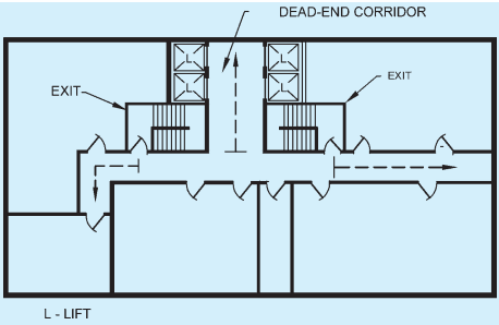
c) The dead end corridor length in exit access shall not exceed 6 m for educational, institutional and assembly occupancies. For other occupancies, the same shall be 15 m (see Fig. 6)
d) Exits shall be placed as remote from each other as possible and shall be arranged to provide direct access in separate directions from any point in the area served.
FIG. 6 DEAD END CORRIDOR
4.4.2.3 Capacities of means of egress
a) Exit capacity is the number of people that can pass through a stairway, and level components (door and corridor) and ramps. The total capacity of all the respective means of egress serving a floor shall be sufficient to allow egress of the entire population of the floor.
b) The unit of exit width, used to measure the capacity of any exit, shall be 500 mm. A clear width of 250 mm shall be counted as an additional half unit. Clear widths less than 250 mm shall not be counted for exit width.
c) Width per person for stairways, and level components and ramps shall be determined using the capacity factors in accordance with Table 4.
Table 4 Capacity Factors
[Clauses 4.4.2.1, 4.4.2.3(c) and 4.4.2.4.2(a)]
Sl No.
Occupancy Group
Width per Person mm
Stairways
Level Components and Ramps
(1)
(2)
(3)
(4)
i)
Residential
(Group A)
10
6.5
ii)
Educational
(Group B)
iii)
Institutional
(Group C)
15
13
iv)
Assembly
(Group D)
v)
Business
(Group E)
vi)
Mercantile
(Group F)
10
6.5
vii)
Industrial
(Group G)
viii)
Storage
(Group H)
ix)
Hazardous
(Group J)
18
10
For example, if an exit doorway measures 1 000 mm in clear width, it would be defined as providing exit capacity for 1 000/6.5 occupants, that is, 153 persons (say 150 persons) and number of such exit doorways can then be calculated depending on the occupant load.
d) When calculating stairways, level components and ramps and other exit means, the capacity of the entire system shall have to be based upon the minimum capacity available from any part of the system. The corridor, if so provided shall also to be planned with consideration of exit access adequacy for the number of occupants. Further, consider the situation of doors opening to an exit stairway. If the stairway provides an exit capacity of 150 persons, and the doors leading into the stairway provide an exit capacity of 153 persons, the overall exit system would be considered to provide the minimum exit capacity of only 150 persons afforded by the stairway. The exit planning will be limited by the most restrictive exit calculation under the means of egress.
4.4.2.4 Types of exit access and exits
Various types of exit access and exits are doorways, corridors and passageways, horizontal exits, internal
Table 5Travel Distance (Based on Occupancy and Construction Type) (Clauses 4.4.2.1 and 4.4.2.2)
Sl No.
Occupancy Group
Maximum Travel Distance m
Types 1 and 2
Types 3 and 4
(1)
(2)
(3)
(4)
i)
Residential (Group A)
30.00
22.50
ii)
Educational (Group B)
30.00
22.50
iii)
Institutional (Group C)
30.00
22.50
iv)
Assembly (Group D)
30.00
30.00
v)
Business (Group E)
30.00
30.00
vi)
Mercantile (Group F)
30.00
30.00
vii)
Industrial (Group G)
G-1, G-2
45.00
See Note 3
G-3
22.50
viii)
Storage (Group H)
30.00
ix)
Hazardous (Group J)
22.50
NOTES
1 For fully sprinklered building, the travel distance may be increased by 50 percent of the values specified.
2 Ramp shall not be counted as an exit in case of basements below the first basement in car parking.
3 Construction of Type 3 or Type 4 is not permitted.
staircases, exit passageways, external staircases and ramps.
Requirements for each are as detailed below.
4.4.2.4.1 Doorways
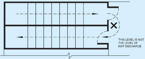
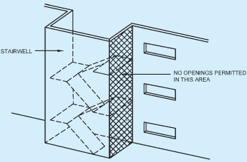
a) Every exit doorway shall open into an enclosed stairway or a horizontal exit of a corridor or passageway providing continuous and protected means of egress (see Fig. 7 on unaccepted arrangement of doors in a stair).
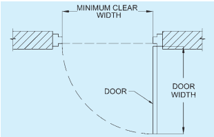
b) No exit doorway shall be less than 1 000 mm in width except assembly buildings, where door width shall be not less than 2 000 mm (see Fig. 8). Doorways shall be not less than 2 000 mm in height.
c) Exit doorways shall be operable from the side which they serve, without the use of a key.
d) Mirrors shall not be placed on exit doors and in exits to avoid confusion regarding the direction of exit.
4.4.2.5 Smoke control of exits
a) In building design, compartmentation plays a vital part in limiting the spread of fire and smoke. The design should ensure avoidance of spread of smoke to adjacent spaces through the various leakage openings in the compartment enclosure, such as cracks, openings around pipes ducts, airflow grills and doors. In the absence of proper sealing of all these openings, smoke and toxic gases will obstruct the free movement of occupants of the building through the exits. Pressurization of staircases is of great importance for the
exclusion of smoke and toxic gases from the protected exit.
b) Pressurization is a method adopted for protecting the exits from ingress of smoke, especially in high-rise buildings. In pressurization, air is injected into the staircases, lobbies, etc, as applicable, to raise their pressure slightly above the pressure in adjacent parts of the building. As a result, ingress of smoke or toxic gases into the exits will be prevented. The pressurization of staircases and lift lobbies shall be adopted as given in Table 6.
The pressure difference for staircases shall be 50 Pa.
Pressure differences for lobbies (or corridors) shall be between 25 Pa and 30 Pa. Further, the pressure differential for enclosed staircase adjacent to such lobby (or corridors) shall be 50 Pa. For enclosed staircases adjacent to non-pressurized lobby (or corridors), the pressure differential shall be 50 Pa.
Table 6Pressurization of Staircases and Lift Lobbies [Clauses 4.4.2.5 (b) and E-2]
Sl No.
Component
Height of Building
Less than 15 m(3)
15 m to 30 m(4)
More than 30 m(5)
i)
Internal staircase not with external wall
Pressurized except for residential buildings (A-2 and A-4)
Pressurized
Pressurized
ii)
Internal staircase with external wall
Pressurized except for residential buildings (A-2 and A-4) or Naturally ventilated
Naturally ventilated or Pressurized
Cross-ventilated or Pressurized
iii)
Lift lobby
Not required at ground and above.However lift lobby segregation and pressurization is required for lift commuting from ground to basement
Naturally ventilated or Pressurized1)
Cross-ventilated or Pressurized1)
NOTES1 The natural ventilation requirement of the staircase shall be, achieved through opening at each landing, of an area 0.5 m² in the external wall. A cross ventilated staircase shall have 2 such openings in opposite/adjacent walls or the same shall be cross-ventilated through the corridor.2 Enclosed staircase leading to more than one basement shall be pressurized.
4.4Wind Speed
4.4.1 Nature of Wind in Atmosphere
In general, wind speed in the atmospheric boundary layer increases with height from zero at ground level to maximum at a height called the gradient height. There is usually a slight change in direction (Ekman effect) but this is ignored in this Section. The variation with height depends primarily on the terrain conditions. However, the wind speed at any height never remains constant and it has been found convenient to resolve its instantaneous magnitude into an average or mean value and a fluctuating component around this average value. The average value depends on the average time employed in analyzing the meteorological data and this averaging time varies from few seconds to several minutes. The magnitude of fluctuating component of the wind speed, which is called gust, depends on the averaging time. In general, smaller the averaging interval more is the magnitude of the gust speed.
4.4.2 Basic Wind Speed
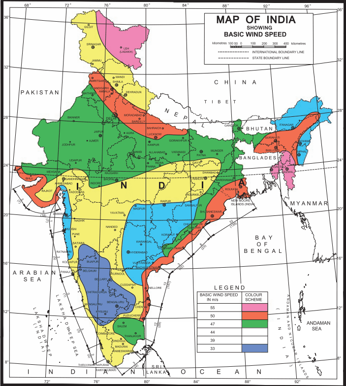
Figure 1 gives basic wind speed map of India, as applicable to 10 m height above mean ground level for different zones of the country. Basic wind speed is based on peak gust velocity averaged over a short time interval of about 3 s and corresponds to mean heights above ground level in an open terrain (Category 2). Basic wind speeds presented in Fig. 1 have been worked out for a 50 year return period. Basic wind speed for some important cities/towns is also given in Annex C.
4.4.3 Design Wind Speed (Vz)
The basic wind speed (Vb) for any site shall be obtained from Fig. 1 and shall be modified to include the following effects to get design wind speed, Vz at any height z, for the chosen structure:
a) Risk level,
b) Terrain roughness and height of structure,
c) Local topography, and
d) Importance factor for the cyclonic region.
It can be mathematically expressed as follows:
V z = V b k ₁ k ₂ k ₃ k ₄
where
Vz = design wind speed at height z, in m / s;
k₁ = probability factor (risk coefficient)
(see 4.4.3.1);
k₂ = terrain roughness and height factor (see 4.4.3.2);
k₃ = topography factor (see 4.4.3.3); and
k₄ = importance factor for the cyclonic region (see 4.4.3.4).
NOTE — Wind speed may be taken as constant up to a height of 10 m. However, pressures for buildings less than 10 m high may be reduced by 20 percent for evaluating stability and design of the framing.
4.4.3.1 Risk coefficient (k1 factor)
Figure 1 gives basic wind speeds for Terrain Category 2 as applicable at 10 m above ground level based on 50 years mean return period. The suggested life period to be assumed in design and the corresponding k₁ factors for different class of structures for the purpose of design are given in Table 4. In the design of buildings and structures, a regional basic wind speed having a mean return period of 50 years shall be used except as specified in Note of Table 4.
4.4.3.2 Terrain, height factor (k2 factor)
4.4.3.2.1 Terrain
Selection of terrain categories shall be made with due regard to the effect of obstructions which constitute the ground surface roughness. The terrain category used in the design of a structure may vary depending on the direction of wind under consideration. Wherever sufficient meteorological information is available about the nature of wind direction, the orientation of any building or structure may be suitably planned.
Terrain in which a specific structure stands shall be assessed as being one of the following terrain categories:
a) Category 1 — Exposed open terrain with few or no obstructions and in which the average height of any object surrounding the structure is less than 1.5 m. The equivalent aerodynamic roughness height, (z0,1) for this terrain is 0.002 m. Typically this category represents open sea-coasts and flat plains without trees.
b) Category 2 — Open terrain with well scattered obstructions having heights generally between 1.5 m and 10 m. The equivalent aerodynamic roughness height, (z0,2) for this terrain is 0.02 m. This is the criterion for measurement of regional basic wind speeds and represents airfields, open park lands and undeveloped spar-sely built-up outskirts of towns and suburbs. Open land adjacent to sea coast may also be classified as Category 2 due to roughness of large sea waves at high winds.
c) Category 3 — Terrain with numerous closely spaced obstructions having the size of buildings/structures up to 10 m in height with or without a few isolated tall structures. The equivalent aerodynamic roughness height, (z0,3) for this terrain is 0.2 m. This category represents well wooded areas, and shrubs, towns and industrial areas full or partially
4.4.3.3 Topography (k3 factor)
The basic wind speed Vb given in Fig. 1 takes into account the general level of site above sea level. This does not allow for local topographic features such as hills, valleys, cliffs, escarpments, or ridges which can significantly affect wind speed in their vicinity. The effect of topography is to accelerate wind near the summits of hills or crests of cliffs, escarpments or ridges and decelerate the wind in valleys or near the foot of cliffs, steep escarpments, or ridges.
Table 6Fetch and Developed Height Relationship (Clause 4.4.3.2.4)
Sl No.
Fetch (x) km
Developed Height ( hx ) m
Terrain Category 1
Terrain Category 2
Terrain Category 3
Terrain Category 4
(1)
(2)
(3)
(4)
(5)
(6)
i)
0.2
12
20
35
60
ii)
0.5
20
30
35
95
iii)
1
25
45
80
130
iv)
2
35
65
110
190
v)
5
60
100
170
300
vi)
10
80
140
250
450
vii)
20
120
200
350
4.4.3.4 Importance factor for cyclonic region (k4 factor)
The east coast of India is relatively more vulnerable for occurrences of severe cyclones. On the west coast, Gujarat is vulnerable for severe cyclones. Studies of wind speed and damage to buildings and structures point to the fact that the speeds given in the basic wind speed map are often exceeded during the cyclones. The effect of cyclonic storms is largely felt in a belt of approximately 60 km width at the coast. In order to ensure better safety of structures in this region (60 km wide on the east coast as well as on the Gujarat Coast), the following values of k₄ , as recommended in good practice [6-1(5)] are stipulated as applicable according to the importance of the structure:
k₄
Structures of post-cyclone importance for emergency services(such as cyclone shelters, hospitals, schools, communication towers, etc)
1.30
Industrial structures
1.15
All other structures
1.00
4.4.4 Hourly Mean Wind Speed
The hourly mean wind speed at height z, for different terrains can be obtained as:
Vz,H=kˉ
4.4.5 Turbulence Intensity
The turbulence intensity variations with height for different terrains can be obtained using the relations given below:
a) Terrain category 1
Iz,1=0.3507−0.0535log10
4.4.6 Off-Shore Wind Velocity
Cyclonic storms form far away from the sea coast and gradually reduce in speed as they approach the sea coast. Cyclonic storms generally extend up to about 60km inland after striking the coast. Their effect on land is already reflected in basic wind speeds specified in Fig. 1. The influence of wind speed off the coast up to a distance of about 200km may be taken as 1.15 times the value on the nearest coast in the absence of any definite wind data. The factor 1.15 shall be used in addition to k₄.
4.5Wind Pressures and Forces on Buildings/Structures
4.5.1 General
The wind load on a building/structure shall be
calculated for,
a) the building/structure as a whole;
b) individual structural elements as roofs and walls; and
c) Individual cladding units including glazing and their fixings.
4.5.2 Design Wind Pressure
The wind pressure at any height above mean ground level shall be obtained by the following relationship between wind pressure and wind speed:
p z = 0. 6 V z ²
where
p z = wind pressure at height z, in N / m ²; and
V z = design wind speed at height z, in m / s.
The design wind pressure pd can be obtained as,
p d = K d K a K c p z
where
K d = wind directionality factor ,
K a = area averaging factor, and
K c = combination factor [see 4.5.3.3.13]
The value of pd, however shall not be taken as less than 0.70 pz.
NOTES
1 The coefficient 0.6 (in SI units) in the above formula depends on a number of factors and mainly on the atmospheric pressure and air temperature. The value chosen corresponds to the average Indian atmospheric conditions.
2 Kd should be taken as 1.0 when considering local pressure coefficients.
4.5.2.1 Wind directionality factor, Kd
Considering the randomness in the directionality of wind and recognizing the fact that pressure or force coefficients are determined for specific wind directions, it is specified that for buildings, solid signs, open signs, lattice frameworks, and trussed towers (triangular, square, rectangular) a factor of 0.90 may be used on the design wind pressure. For circular or near-circular forms this factor may be taken as 1.0.
For the cyclone affected regions also the factor Kd shall be taken as 1.0.
4.5.2.2 Area averaging factor, Ka
Pressure coefficients given in 4.5.3 are a result of averaging the measured pressure values over a given area. As the area becomes larger, the correlation of measured values decrease and vice-versa. The decrease in pressures due to larger areas may be taken into account as given in Table 7.
Table 7Area Averaging Factor ( Ka ) (Clause 4.5.2.2)
Sl No.
Tributary Area (A) m²
Area Averaging Factor (K<sub>a</sub>)1)
(1)
(2)
(3)
i)
≤ 10
1.0
ii)
25
0.9
iii)
≥ 100
0.8
¹⁾ Linear interpolation for intermediate values of tributary area, A is permitted.
4.5.2.2.1 Tributary area
a) Overall structure — For evaluating loads on frames the tributary area shall be taken as the centre-to-centre distances between frames multiplied by the individual panel dimension in the other direction together with overall pressure coefficients.
b) Individual elements — For beam type elements, purlins, etc, the tributary area shall be taken as effective span multiplied by spacing. The effective span is the actual span for mid span and cantilever load effects; and half the sum of adjacent spans for support moments and reactions.
c) For plate type elements, the area of individual plates between supports is taken as the tributary area.
d) For glass cladding, individual pane area of glass is the tributary area.
4.5.3 Pressure Coefficients
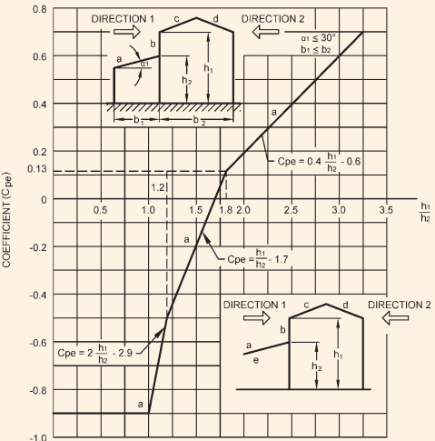
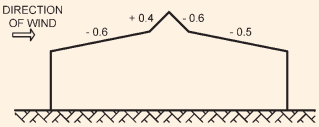
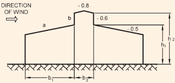
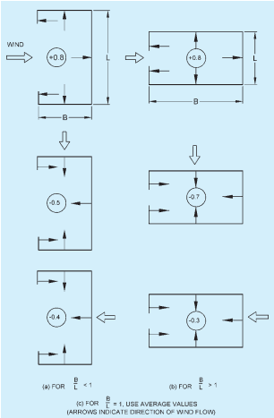
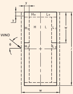
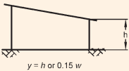
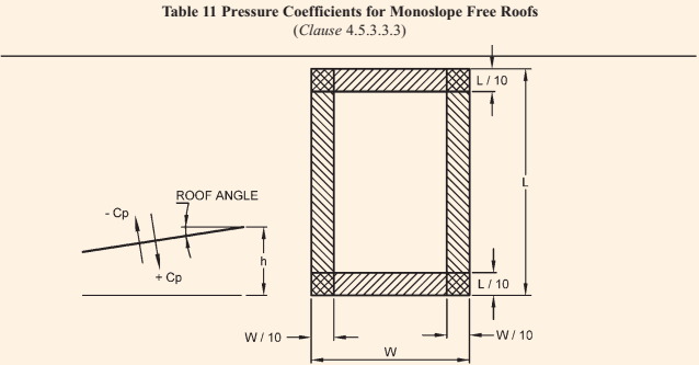
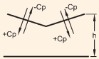
The pressure coefficients are always given for a particular surface or part of the surface of a building/structure. The wind load acting normal to a surface is obtained by multiplying the area of that surface or its appropriate portion by the pressure coefficient (Cp) and the design wind pressure at the height of the surface from the ground. The average values of these pressure coefficients for some building shapes are given in 4.5.3.2 and 4.5.3.3.
Average values of pressure coefficients are given for critical wind directions in one or more quadrants. In order to determine the maximum wind load on the building/structure, the total load should be calculated for each of the critical directions shown from all quadrants. Where considerable variation of pressure occurs over a surface, it has been sub-divided and mean pressure coefficients given for each of its several parts.
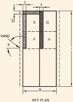
In addition, areas of high local suction (negative pressure concentration) frequently occurring near the edges of walls and roofs are separately shown. Coefficients for the local effects should only be used for calculation of forces on these local areas affecting
roof sheeting, glass panels, and individual cladding units including their fixtures. They should not be used for calculating force on entire structural elements such as roof, walls or structure as a whole.
1 The pressure coefficients given in different tables have been obtained mainly from measurements on models in wind tunnels, and the great majority of data available has been obtained in conditions of relatively smooth flow. Where sufficient field data exists as in the case of rectangular buildings, values have been obtained to allow for turbulent flow.
2 In recent years, wall glazing and cladding design has been a source of major concern. Although of less consequence than the collapse of main structures, damage to glass can be hazardous and cause considerable financial losses.
3 For pressure coefficients for structures not covered herein, reference may be made to specialist literature on the subject or advice may be sought from specialists in the subject.
4.5.3.1 Wind load on individual members
When calculating the wind load on individual structural elements such as roofs and walls, and individual cladding units and their fittings, it is essential to take account of the pressure difference between opposite faces of such elements or units. For clad structures, it is, therefore, necessary to know the internal pressure as well as the external pressure. Then the wind load, F (in N), acting in a direction normal to the individual structural element or cladding unit is:
F = (C pe - C pi) A p d
where
C pe = external pressure coefficient;
C pi = internal pressure coefficient;
A = surface area of structural element or cladding unit, in m²; and
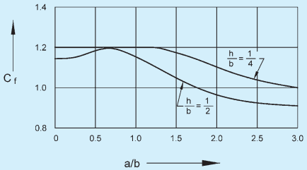
4.5.4 Force Coefficients
The value of force coefficients (Cf) apply to a building or structure as a whole, and when multiplied by the effective frontal area (Ae) of the building or structure and design wind pressure, pd gives the total wind load (F) on that particular building or structure, expressed as:
F = C f A e p d
where F is the force acting in a direction specified in the respective tables and Cf is the force coefficient for the building.
NOTES
1 The value of the force coefficient differs for the wind acting
Table 25 External Pressure Coefficients ( Cpe ) for Roofs with a Sky Light (Clause 4.5.3.3.10)
b) ROOFS WITH A SKY LIGHT
Values of Coefficients ( Cpe )
Portion
b₁ > b₂
b₁ ≤ b₂
a
b
a and b
Cpe
-0.6
+0.7
See Table 24 for combined roofs
4.7Dynamic Effects
4.7.1 General
Flexible slender structures and structural elements shall be investigated to ascertain the importance of wind induced oscillations or excitations in along wind and across wind directions.
In general, the following guidelines may be used for examining the problems of wind-induced oscillations:
a) Buildings and closed structures with a height to minimum lateral dimension ratio of more than about 5.0, or
b) Buildings and structures whose natural frequency in the first mode is less than 1.0Hz.
Any building or structure which satisfies either of the
above two criteria shall be examined for dynamic effects of wind.
1 The fundamental time period (T), in second, may either be established by experimental observations on similar buildings or calculated by any rational method of analysis. In the absence of such data, T may be determined as follows for multi-storeyed buildings:
a) For moment resistant frames without bracings or shear walls resisting the lateral loads,
T = 0. 1 n
where
n = number of storeys, including basement storeys.
b) For all others,
T=d0.09H
where
H = total height of the main structures of the building, in m; and
d = maximum base dimension of building in metre in a direction parallel to the applied wind force.
2 If preliminary studies indicate that wind-induced oscillations are likely to be significant, investigations should be pursued with the aid of analytical methods or if necessary, by means of wind tunnel tests on models.
3 Across-wind motions may be due to lateral gustiness of the wind, unsteady wake flow (for example, vortex shedding), negative aerodynamic damping or due to a combination of these effects. These cross-wind motions may become critical in the design of tall buildings/structures.
4 Motions in the direction of wind (also known as buffeting) are caused by fluctuating wind force associated with gust. The excitation depends on gust energy available at the resonant frequency.
5 The eddies shed from an upstream body may intensify motion in the direction of the wind and may also affect cross-wind motion.
6 The designer should also be aware of the following three forms
of wind-induced motion which are characterized by increasing amplitude of oscillation with the increase of wind speed:
a) Galloping — Galloping is transverse oscillations of some structures due to the development of aerodynamic forces which are in phase with the motion. It is characterized by the progressively increasing amplitude of transverse vibration with increase of wind speed. The cross-sections which are particularly prone to this type of excitation include the following:
All structures with non-circular cross-sections, such as triangular, square, polygons, as well as angles, crosses, and T sections.
Twisted cables and cables with ice encrustations.
b) Flutter — Flutter is unstable oscillatory motion of a structure due to coupling between aerodynamic force and elastic deformation of the structure. Perhaps the most common form is oscillatory motion due to combined bending and torsion. Although oscillatory motion in each degree of freedom may be damped, instability can set in due to energy transfer from one mode of oscillation to another and the structure is seen to execute sustained or divergent oscillations with a type of motion which is a combination of the individual modes of vibration. Such energy transfer takes place when the natural frequencies of modes taken individually are close to each other (ratio being typically less than 2.0). Flutter can set in at wind speeds much less than those required for exciting the individual modes of motion. Long span suspension bridge decks or any member of a structure with large values of d/t (where d is the length of the member and t is its dimension parallel to wind stream) are prone to low speed flutter. Wind tunnel testing is required to determine critical flutter speeds and the likely structural response. Other types of flutter are single degree of freedom stall flutter, torsional flutter, etc.
c) Ovalling — Thin walled structures with open ends at one or both ends such as oil storage tanks and natural draught cooling towers in which the ratio of the diameter or minimum lateral dimension to the wall thickness is of the order of 100 or more are prone to ovalling oscillations. These oscillations are characterized by periodic radial deformation of the hollow structure.
7 Buildings and structures that may be subjected to significant wind excited oscillations require careful investigations. It is to be noted that wind induced oscillations may occur at wind speeds lower than the design wind speed.
8 Analytical methods for the evaluation of response of dynamic structures to wind loading can be found in the special publications.
9 In assessing wind loads due to such dynamic phenomenon as galloping, flutter and ovalling, in the absence of the required information either in the special publications or other literature, expert advice should be sought including experiments on models in boundary layer wind tunnels.
4.7.2 Motion due to Vortex Shedding
4.7.2.1 Slender structures
For a structure, the vortex shedding frequency, fs, shall be determined by the following formula:
fs=bSt
5Seismic Force
This clause primarily deals with earthquake hazard assessment and earthquake-resistant design of buildings.
All structures, like parking structures, security cabins and ancillary structures need to be designed for
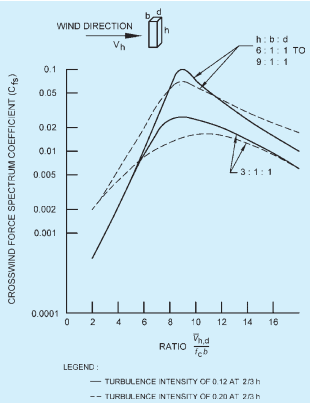
10A VALUES OF THE CROSS WIND FORCE SPECTRUM COEFFICIENT FOR SQUARE SECTION BUILDINGS
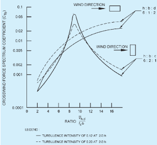
10B VALUES OF THE CROSS WIND FORCE SPECTRUM COEFFICIENT FOR 2:1 AND 1:2 RECTANGULAR SECTION BUILDINGS
FIG. 10 WIND FORCE SPECTRUM COEFFICIENT
appropriate earthquake effects as per this clause. Also, temporary elements, such as scaffolding and temporary excavations, need to be designed as per this clause. This clause does not deal with construction features relating to earthquake-resistant buildings and other
structures. For guidance on earthquake-resistant construction of buildings, reference may be made to the latest revisions of the following good practice [6 1(6)].
The provisions of this clause are applicable even to critical and special structures, like nuclear power plants and petroleum refinery plants. For such structures, additional requirements may be imposed based on special studies, such as site-specific hazard assessment. In such cases, the earthquake effects specified by this clause shall be taken as at least the minimum.
For the purpose of this clause the symbols given at Annex G are applicable.
3.8Fire Tenders and Emergency Vehicles
Where a structure or portions of a structure are accessed and loaded by fire department access vehicles and other similar emergency vehicles, the structure shall be designed for the greater of the following loads:
a) The actual operational loads, including outrigger reactions and contact areas of the vehicles as stipulated and provided by the building official.
b) The contact area of wheel dimensions to be used considering 45° distribution at the reinforcement of slab considering the bear coat on the slab and any soil filling.
or
In absence of any data the bare slab loading may be considered as 15 to 20kN / m².
c) When the fire tender load is combined with
gravity loads and the same can be considered as accidental load with the partial load factor of 1.05.
d) Fire tender load need not be combined with lateral loads.
5.1Terminology
For the purpose of this clause, definitions given below shall apply to all structures, in general. For definition of terms pertaining to soil mechanics and soil dynamics, reference may be made to Part 6 ‘Structural Design, Section 2 Soils and Foundations’ of the Code; and for definition of terms pertaining to ‘Loads’, 3.2 and 4.3 may be referred.
5.1.1 Closely-Spaced Modes — Closely-spaced modes of a structure are those of the natural modes of oscillation of a structure, whose natural frequencies differ from each other by 10 percent or less of the lower frequency.
5.1.2 Critical Damping — The damping beyond which the free vibration motion will not be oscillatory.
5.1.3 Damping — The effect of internal friction, inelasticity of materials, slipping, sliding, etc, in reducing the amplitude of oscillation; it is expressed as a fraction of critical damping (see 5.1.2).
5.1.4 Design Acceleration Spectrum — Design acceleration spectrum refers to an average smoothened graph of maximum acceleration as a function of natural frequency or natural period of oscillation for a specified damping ratio for the expected earthquake excitations at the base of a single degree of freedom system.
5.1.5 Design Horizontal Acceleration Coefficient (Ah) — It is a horizontal acceleration coefficient that shall be used for design of structures.
5.1.6 Design Horizontal Force — It is the horizontal seismic force prescribed by this Section that shall be used to design a structure.
5.1.7 Ductility — It is the capacity of a structure (or its members) to undergo large inelastic deformations without significant loss of strength or stiffness.
5.1.8 Epicentre — It is the geographical point on the
surface of earth vertically above the point of origin of the earthquake.
5.1.9 Floor Response Spectrum — It is the response spectrum (for a chosen material damping value) of the time history of the shaking generated at a floor of a structure, when the structure is subjected to a given earthquake ground motion at its base.
5.1.10 Importance Factor (I) — It is a factor used to estimate design seismic force depending on the functional use of the structure, characterized by hazardous consequences of its failure, post-earthquake functional needs, historical value, or economic importance.
5.1.11 Intensity of Earthquake — It is the measure of the strength of ground shaking manifested at a place during the earthquake, and is indicated by a roman capital numeral on the MSK scale of seismic intensity (see Annex H).
5.1.12 Liquefaction — It is a state primarily in saturated cohesionless soils wherein the effective shear strength is reduced to negligible value for all engineering purposes, when the pore pressure approaches the total confining pressure during earthquake shaking. In this condition, the soil tends to behave like a fluid mass (see Annex J).
5.1.13 Lithological Features — Features that reflect the nature of the geological formation of the earth's crust above bed rock characterized on the basis of structure, mineralogical composition and grain size.
5.1.14 Modal Mass ( Mk ) in Mode (k) of a Structure — It is a part of the total seismic mass of the structure that is effective in natural mode k of oscillation during horizontal or vertical ground motion.
5.1.15 Modal Participation Factor ( Pk ) in Mode (k) of a Structure — The amount by which natural mode k contributes to overall oscillation of the structure during horizontal or vertical earthquake ground motion. Since the amplitudes of mode shapes can be scaled arbitrarily, the value of this factor depends on the scaling used for defining mode shapes.
5.1.16 Modes of Oscillation — See 5.1.19.
5.1.17 Mode Shape Coefficient ( φik ) — It is the spatial deformation pattern of oscillation along degree of freedom i, when the structure is oscillating in its natural mode k. A structure with N degrees of freedom possesses N natural periods and N associated natural mode shapes. These natural mode shapes are together presented in the form of a mode shape matrix [ φ ], in which each column represents one natural mode shape. The element φik is called the mode shape coefficient
associated with degree of freedom i, when the structure is oscillating in mode k.
5.1.18 Natural Period ( Tk ) in Mode (k) of Oscillation — The time taken (in second) by the structure to complete one cycle of oscillation in its natural mode k of oscillation.
5.1.18.1 Fundamental lateral translational natural period (T₁) — It is the longest time taken (in second) by the structure to complete one cycle of oscillation in its lateral translational mode of oscillation in the considered direction of earthquake shaking. This mode of oscillation is called the fundamental lateral translational natural mode of oscillation. A three-dimensional model of a structure will have one such fundamental lateral translational mode of oscillation along each of the two orthogonal plan directions.
5.1.19 Normal Mode of Oscillation — The mode of oscillation in which there are special undamped free oscillations in which all points on the structure oscillate harmonically at the same frequency (or period), such that all these points reach their individual maximum responses simultaneously.
5.1.20 Peak Ground Acceleration — It is the maximum acceleration of the ground in a given direction of ground shaking. Here, the acceleration refers to that of the horizontal motion, unless specified otherwise.
5.1.21 Response Reduction Factor(R) — It is the factor by which the base shear induced in a structure, if it were to remain elastic, is reduced to obtain the design base shear. It depends on the perceived seismic damage performance of the structure, characterized by ductile or brittle deformations, redundancy in the structure, or overstrength inherent in the design process.
5.1.22 Response Spectrum — It is the representation of maximum responses of a spectrum of idealized single degree freedom systems of different natural periods but having the same damping, under the action of the same earthquake ground motion at their bases. The response referred to here can be maximum absolute acceleration, maximum relative velocity, or maximum relative displacement.
5.1.23 Response Acceleration Coefficient of a Structure (Sa/g) — It is a factor denoting the normalized design acceleration spectrum value to be considered for the design of structures subjected to earthquake ground shaking; this value depends on the natural period of oscillation of the structure and damping to be considered in the design of the structure.
5.1.24 Seismic Mass of a Floor — It is the seismic
weight of the floor divided by acceleration due to gravity.
5.1.25 Seismic Mass of a Structure — It is the seismic weight of a structure divided by acceleration due to gravity.
5.1.26 Seismic Weight of a Floor (W) — It is the sum of dead load of the floor, appropriate contributions of weights of columns, walls and any other permanent elements from the storeys above and below, finishes and services, and appropriate amounts of specified imposed load on the floor.
5.1.27 Seismic Weight of a Structure (W) — It is the sum of seismic weights of all floors.
5.1.28 Seismic Zone Factor (Z) — It is the value of peak ground acceleration considered by this Section for the design of structures located in each seismic zone.
5.1.29 Time History Analysis — It is an analysis of the dynamic response of the structure at each instant of time, when its base is subjected to a specific ground motion time history.
5.2Special Terminology for Buildings
5.2.1 The definitions given below shall apply for the purpose of earthquake resistant design of buildings, as enumerated in this Section.
5.2.2 Base — It is the level at which inertia forces generated in the building are considered to be transferred to the ground through the foundation. For buildings with basements, it is considered at the bottommost basement level. For buildings resting on,
a) pile foundations, it is considered to be at the top of pile cap;
b) raft, it is considered to be at the top of raft; and
c) footings, it is considered to be at the top of the footing.
For buildings with combined types of foundation, the base is considered as the bottom-most level of the bases of the constituent individual foundations as per definitions above.
5.2.3 Base Dimension (d) — It is the dimension (in metre) of the base of the building along a direction of shaking.
5.2.4 Centre of Mass (CM) — The point in the floor of a building through which the resultant of the inertia force of the floor is considered to act during earthquake shaking. Unless otherwise stated, the inertia force considered is that associated with the horizontal shaking of the building.
5.2.5 Centre of Resistance (CR)
5.2.5.1 For single storey buildings — It is the point on
the roof of a building through which when the resultant internal resistance acts, the building undergoes,
a) pure translation in the horizontal direction; and
b) no twist about vertical axis passing through the CR.
5.2.5.2 For multi-storey buildings — It is the set of points on the horizontal floors of a multi-storey building through which, when the resultant incremental internal resistances across those floors act, all floors of the building undergo,
a) pure translation in the horizontal direction; and
b) no twist about vertical axis passing through the CR.
5.2.6 Eccentricity
5.2.6.1 Design eccentricity ( edi ) — It is the value of eccentricity to be used for floor i in calculations of design torsion effects.
5.2.6.2 Static eccentricity (esi) — It is the distance between centre of mass (CM) and centre of resistance (CR) of floor i.
5.2.7 Design Seismic Base Shear ( VB ) — It is the horizontal lateral force in the considered direction of earthquake shaking that the structure shall be designed for.
4.8Dynamic Wind Response
4.8.1 General
Tall buildings/structures which are ‘wind sensitive’ shall be designed for dynamic wind loads. Hourly mean wind speed is used as a reference wind speed to be used in dynamic wind analysis. For calculation of along wind loads and response (bending moments, shear forces, or tip deflections) the Gust Factor (GF) method is used as specified in 4.8.2. The across wind design peak base overturning moment and tip deflection shall be calculated using 4.8.3.
4.8.2 Along Wind Response
For calculation of along-wind load effects at a level s on a building/structure, the design hourly mean wind pressure at height z shall be multiplied by the Gust Factor (G). This factor is dependent on both the overall height h and the level s under consideration (see Fig. 9). For calculation of base bending moment and deflection
at the top of the building/structure, ‘s’ should be taken as zero.
Note that 0 < s < h, and s < z < h.
The design peak along wind base bending moment ( Ma ) shall be obtained by summing the moments resulting from design peak along wind loads acting at different heights, z, along the height of the building/structure and can be obtained from,
M
3.0
4.5
10) Balconies
Same as rooms to which they give access but with a minimum of 4.0
1.5 per metre run concentrated at the outer edge
d) Boiler rooms and plant rooms– to be calculated but not less than
5.0
6.7
e) Garages:
1) Garage floors (including parking area and repair workshops for passenger cars and vehicles not exceeding 2.5 tonne gross weight, including access ways and ramps – to be calculated but not less than
2.5
9.0
2) Garage floors for vehicles not exceeding 4.0 tonne gross weight (including access ways and ramps ) – to be calculated but not less than
5.0
9.0
ii) Educational Buildings
a) Class rooms and lecture rooms (not used for assembly purposes)
3.0
2.7
b) Dining rooms, cafeterias and restaurants
3.0¹⁾
2.7
c) Offices, lounges and staff rooms
2.5
2.7
d) Dormitories
2.0
2.7
e) Projection rooms
5.0
—
f) Kitchens
3.0
4.5
g) Toilets and bath rooms
2.0
—
h) Store rooms
5.0
4.5
j) Libraries and archives:
1) Stack room/stack area
6.0 kN/m² for a minimum height of 2.2 m + 2.0 kN/m² per metre height beyond 2.2 m
4.5
Table 1(Continued)
(1)
(2)
(3)
(4)
2) Reading rooms (without separate storage)
4.0
4.5
3) Reading rooms (with separate storage)
3.0
4.5
k) Boiler rooms and plant rooms – to be calculated but not less than
4.0
4.5
m) Corridors, passages, lobbies, staircases including fire escapes – as per the floor serviced (without accounting for storage and projection rooms) but not less than
4.0
4.5
n) Balconies
Same as rooms to which they give access but with a minimum of 4.0
1.5 per metre run concentrated at the outer edge
iii)
Institutional Buildings
a) Bed rooms, wards, dressing rooms, dormitories and lounges
2.0
1.8
b) Kitchens, laundries and laboratories
3.0
4.5
c) Dining rooms, cafeterias and restaurants
3.0¹⁾
2.7
d) Toilets and bathrooms
2.0
-
e) X-ray rooms, operating rooms and general storage areas – to be calculated but not less than
3.0
4.5
f) Office rooms and O.P.D. rooms
2.5
2.7
g) Corridors, passages, lobbies, staircases including fire escapes – as per the floor serviced (without accounting for storage and projection rooms) but not less than
4.0
4.5
h) Boiler rooms and plant rooms – to be calculated but not less than
5.0
4.5
j) Balconies
Same as rooms to which they give access but with a minimum of 4.0
1.5 per metre run concentrated at the outer edge
iv)
Assembly Buildings
a) Assembly areas :
1) With fixed seats²⁾
4.0
-
2) Without fixed seats
5.0
3.6
b) Restaurants (subject to assembly), museums and art galleries and gymnasia
4.0
4.5
c) Projection rooms
5.0
-
d) Stages
5.0
4.5
e) Office rooms, kitchens and laundries
3.0
4.5
f) Dressing rooms
2.0
1.8
g) Lounges and billiards rooms
2.0
2.7
h) Toilets and bathrooms
2.0
-
j) Corridors, passages and staircases including fire escapes
4.0
4.5
k) Balconies
Same as rooms to which they give access but with a minimum of 4.0
1.5 per metre run concentrated at the outer edge
m) Boiler rooms and plant rooms including weight of machinery
7.5
4.5
n) Corridors, passages, subject to loads greater than from crowds, such as wheeled vehicles, trolleys and the like corridors, staircases and passages in grandstands
5.0
4.5
v)
Business and Office Buildings (see also 3.2.1)
a) Rooms for general use with separate storage
2.5
2.7
b) Rooms without separate storage
4.0
4.5
c) Banking halls
3.0
2.7
d) Business computing machine rooms (with fixed computers or similar equipment)
3.5
4.5
e) Records/files store rooms and storage space
5.0
4.5
f) Vaults and strong rooms – to be calculated but not less than
5.0
4.5
g) Cafeterias and dining rooms
3.0¹⁾
2.7
h) Kitchens
3.0
2.7
j) Corridors, passages, lobbies, staircases including fire escapes – as per the floor serviced (excluding stores) but not less than
4.0
4.5
k) Bath and toilets rooms
2.0
-
Table 1(Concluded)
(1)
(2)
(3)
(4)
vi)
m) Balconies
Same as rooms to which they give access but with a minimum of 4.0
1.5 per metre run concentrated at the outer edge
n) Stationary stores
4.0 for each metre of storage height
9.0
p) Boiler rooms and plant rooms – to be calculated but not less than
5.0
6.7
q) Libraries
See SI No. (ii)
Mercantile Buildings
a) Retail shops
4.0
3.6
b) Wholesale shops – to be calculated but not less than
6.0
4.5
c) Office rooms
2.5
2.7
d) Dining rooms, restaurants and cafeterias
3.0¹⁾
2.7
e) Toilets
2.0
-
f) Kitchens and laundries
3.0
4.5
g) Boiler rooms and plant rooms – to be calculated but not less than
5.0
6.7
h) Corridors, passages, staircases including fire escapes and lobbies
4.0
4.5
j) Corridors, passages, staircases subject to loads greater than from crowds, such as wheeled vehicles, trolleys and the like
5.0
4.5
k) Balconies
Same as rooms to which they give access but with a minimum of 4.0
1.5 per metre run concentrated at the outer edge
vii)
Industrial Buildings³⁾
a) Work areas without machinery/equipment
2.5
4.5
b) Work areas with machinery/equipment⁴⁾
1) Light duty To be calculated
5.0
4.5
2) Medium duty but not less
7.0
4.5
3) Heavy duty than
10.0
4.5
c) Boiler rooms and plant rooms – to be calculated but not less than
5.0
6.7
d) Cafeterias and dining rooms
3.0¹⁾
2.7
e) Corridors, passages, stair cases including fire escapes
4.0
4.5
f) Corridors, passages, lobbies, staircases subject to machine loads and wheeled vehicles – to be calculated but not less than
5.0
4.5
g) Kitchens
3.0
4.5
h) Toilets and bathrooms
2.0
-
viii)
Storage Buildings⁴⁾
a) Storage rooms (other than cold storage) and warehouses — to be calculated based on the bulk density of materials stored but not less than
2.4 kN/m² per metre of storage height with a minimum of 7.5 kN/m²
7.0
b) Cold storage – to be calculated but not less than
5.0 kN/m² per metre of storage height with a minimum of 15 kN/m²
9.0
c) Corridors, passages, staircases including fire escapes – as per the floor serviced but not less than
4.0
4.5
d) Corridors, passages subject to loads greater than from crowds, such as wheeled vehicles, trolleys and the like
5.0
4.5
e) Boiler rooms and plant rooms
7.5
4.5
¹⁾ Where unrestricted assembly of persons is anticipated, the value of UDL should be increased to 4.0 kN/m ² .
²⁾ With fixed seats implies that the removal of the seating and the use of the space for other purposes is improbable. The maximum likely load in this case is, therefore, closely controlled.
³⁾ The loading in industrial buildings (workshops and factories) varies considerably and so three loadings under the terms ‘light’, ‘medium’ and ‘heavy’ are introduced in order to allow for more economical designs but the terms have no special meaning in themselves other than the imposed load for which the relevant floor is designed. It is, however important particularly in the case of heavy weight loads, to assess the actual loads to ensure that they are not in excess of 10 kN/m² ; in case where they are in excess, the design shall be based on the actual loadings.
⁴⁾ For various mechanical handling equipment which are used to transport goods, as in warehouses, workshops, store rooms, etc, the actual load coming from the use of such equipment shall be ascertained and design should cater to such loads.
considered to be applied in the positions which produce the maximum stresses and where deflection is the main criterion in the positions which produce the maximum deflections. Concentrated load, when used for the calculation of bending and shear, are assumed to act at a point. When used for the calculation of local effects such as crushing or punching, they are assumed to act over an actual area of application of 0.3 m × 0.3 m .
a) For single bay frames — Effect of one crane in the bay giving the worst effect shall be considered for calculation of surge force; and
b) For multi-bay frames — Effect of two cranes working, one each in any of two bays in the cross-section to give the worst effect shall be considered for calculation of surge force.
3.6.4.3 Tractive force
3.6.4.3.1 Where one crane is in operation with no provision for future crane, tractive force from only one crane shall be taken.
3.6.4.3.2 Where more than one crane is in operation
or there is provision for future crane, tractive force from two cranes giving maximum effect shall be considered.
NOTE — Lateral surge force and longitudinal tractive force acting across and along the crane rail respectively shall not be assumed to act simultaneously. However, if there is only one crane in the bay, the lateral and longitudinal forces may act together simultaneously with vertical loads.
e) In the procedures for determining required egress capacity, the number of required means of egress is based on a floor-by-floor consideration, rather than the accumulation of the occupant loads of all the floors. However, the number of means of egress cannot decrease as an occupant proceeds along the egress path.
e) Revolving doors can be accepted as a component in a means of egress where the following requirements are fully complied with:
Doors shall be capable of collapsing to a book fold position with parallel egress paths, of width not less than 1 000 mm.
Doors shall not be located within 3 m of the foot or top of stairs or escalators. A dispersal area shall be provided between the stairs or escalators and the doors.
f)
g)
Each revolving door shall be provided with a hinged door in the same wall within 3m thereof, with same exiting capacity.
Each revolving door shall be considered as capable of exiting only 50 persons.
All fire rated doors and assembly shall be provided with certificate and labels prominently indicating the manufacturer's identification, door details covering door type, serial/batch number, month and year of manufacture, fire resistance rating, etc. The doors and assembly shall be certified with all prescribed hardware such as hinges, locks, panic bars, door closer, and door viewers.
Access controlled doors — Access controlled doors and electromagnetic doors shall fall under this category. These shall meet the following requirements:
Doors shall have fire rating as per the requirements at the location of installation.
Activation of the building automatic sprinkler or fire detection system, if provided, shall automatically unlock the doors in the direction of egress, and the doors shall remain unlocked until the automatic sprinkler system or fire-alarm system has been manually reset.
Loss of power to the part of the access control system that locks the doors shall automatically unlock the doors in the direction of egress.
A manual release device shall be provided in the readily accessible vicinity of the egress door with a signage ‘PUSH TO EXIT’ and when the same is operated, it shall result in direct interruption of power to the lock, independent of the access control system electronics.
h) Turnstiles — Turnstiles or similar devices that restrict travel to one direction or are used to collect fares or admission charges shall not be placed so as to obstruct any required means of egress unless door openings of required width are available within 3 m thereof.
Turnstiles or such similar devices shall also be disengaged through automatic or manual intervention to allow egress in the direction of exit.
j) Doors in folding partition shall not be treated as approved means of egress.
4.4.2.4.2 Corridors and passageways of means of egress
a) Corridors and passageways shall be of width not less than the calculated aggregate width
FIG. 7 UNACCEPTABLE ARRANGEMENT FOR ENCLOSING A STAIR SERVING AS A REQUIRED EXIT
FIG. 8 MINIMUM CLEAR DOOR WIDTH
of exit doorways leading from them in the direction of travel to the exit (see Table 4 and Table 5).
b) In the case of buildings where there is a central corridor, which is part of exit access, the doors of rooms (except for rooms having assembly occupancy) shall open inwards to permit smooth flow of traffic in the corridor.
4.4.2.4.3 Staircases
4.4.2.4.3.1 General
The requirements of number of staircases shall supplement the requirement of different occupancies in 6.1 to 6.9.
All buildings, as mentioned in 1.2, shall have a minimum of two staircases. The actual number of staircases shall comply with the requirement of 4.4.2.1.
All exit staircases shall discharge, at the level of exit discharge, to the exit discharge, either,
a) directly, or
b) through an exit passageway, or
c) through a large lobby.
At least 50 percent of the staircases shall discharge as per (a) and/or (b) above.
The minimum width of tread without nosing shall be 250 mm for staircase of residential buildings. This shall be minimum 300 mm for assembly, hotels, educational, institutional, business and other buildings. The treads shall be constructed and maintained in a manner to prevent slipping. The maximum height of riser shall be 190 mm for staircase of residential buildings (A-2) and 150 mm for other buildings. The number of risers shall be limited to 12 per flight.
The staircases may be internal staircases or external staircases.
4.4.2.4.3.2 Internal staircases
The internal staircases may be constructed with an external wall, or otherwise, and shall comply with the following:
a) Internal stairs shall be constructed of non-combustible materials throughout, and shall have fire resistant rating of minimum 120 min.
b) A staircase shall not be arranged round a lift shaft.
c) Exits shall not be used as a portion of a supply, return or exhaust air system serving adjoining areas. Any opening(s) shall not be permitted in walls or in doors, separating exits from adjoining areas.
d) No flue chimney, electromechanical equipment, air conditioning units, gas piping or electrical panels shall be allowed in the stairway.
e) Notwithstanding the detailed provision for exits in accordance with 4.2 and 4.3, the following minimum width shall be provided for staircases for respective occupancies:
1) Residential (A-2) : 1.00 m
NOTE — For row housing with 2 storeys, the minimum width shall be 0.75 m.
Residential (A-1, A-3 and : 1.25 m A-4)
Residential hotel (A-5 and : 1.50 m A-6)
Assembly : 2.00 m
NOTE — The width of stairs may be accepted to be 1.50 m in case of assembly occupancy having less than 150 persons.
Educational : 1.50 m
Institutional : 2.00 m
All other occupancies : 1.50 m
f) A handrail shall be provided on one side of the staircase of width less than 1 500 mm, and on both sides of the staircase of width 1 500 mm and more. The projection of handrail(s) in the staircase width shall not be more than 115 mm. All other requirements of handrail shall be in accordance with Part 3 ‘Development Control Rules and General Building Requirements’ of the Code.
g) Handrails may project inside the measured width by not more than 90 mm.
h) The design of staircase shall also take into account the following:
The minimum headroom in a passage under the landing of a staircase and under the staircase shall be 2.2 m
Access to exit staircase shall be through a fire door of a minimum 120 min fire resistance rating.
No living space, store or other fire risk shall open directly into staircases.
The exit (including staircases) shall be continuous from refuge floors or terrace level, as applicable, to the level of exit discharge.
No electrical shafts/air conditioning ducts or gas pipes, etc, shall pass through or open in the staircases.
Lifts shall not open in staircase.
No combustible material shall be used for decoration/wall panelling in the staircase.
Beams/columns and other building features shall not reduce the head room/width of the staircase.
The floor indication board, indicating the location/designated number of staircase, respective floor number and direction to exit discharge shall be placed inside the staircase, on the wall nearest to the fire door. It shall be of size not less than 300 mm × 200 mm (see Fig. 9).
Individual floors shall be prominently indicated on the wall outside the staircase and facing it.
All staircase shall terminate at the level of exit discharge. The access to the basement shall be by a separate staircase.
Scissors type staircases shall not be treated as part of exit.
4.4.2.4.3.3 Curved stairs
Curved stairs shall not be treated as part means of egress. However, these may be used as part of exit access provided the depth of tread is not less than 280 mm at a point 350 mm from the narrower end of the tread and the smallest radius is not less than twice the stair width.
4.4.2.4.3.4 External staircases
The external staircases are the staircases provided on the external wall/facade, and shall comply with the following:
a) External stairs shall always be kept in sound and usable condition.
b) All external stairs shall be directly connected to the ground.
c) Entrance to the external stairs shall be separate and remote from the internal staircase.
d) Where an external staircase is provided, it shall be ensured that the use of it at the time of fire is not prejudiced by smoke and flame from openings (for example, windows, doors) in the external face of the building. Care shall be taken to ensure that no external wall or window opening opens on to or close to an external stair. If such openings exist within 3 m from an external staircase, they shall be protected with fire rated doors/window assemblies with rating of at least 60 min (see Fig. 10).
e) The external stairs shall be constructed of non-combustible materials, and any doorway leading to it shall have minimum 120 min fire resistance.
f) No external staircase, shall be inclined at an angle greater than 45° from the horizontal.
g) External stairs shall have straight flight not less than 1 500 mm wide.
h) Handrails, to be provided on both sides, shall be of a height not less than 1 000 mm and not exceeding 1 200 mm. There shall be provisions of balusters with maximum gap of 150 mm.
j) The use of spiral staircase shall be limited to low occupant load and to a building not exceeding 9 m in height. A spiral staircase shall be not less than 1 500 mm in diameter and shall be designed to give adequate headroom.
9A EXAMPLE OF A STAIRWAY MARKING SIGN [FLOOR INDICATION BOARD]
9B STAIR SIGN PLACEMENT
NOTE — Block/Wing/Building name are to be project specific. Staircase shown as '3' is intending to show the number assigned to the staircase. All exits preferably to be assigned with number/identification enabling occupants/fire man to declare location/position.
FIG. 9 SIGN MARKING AND REQUIREMENT IN EXIT
4.4.2.4.3.5 Ramps
a) Ramps shall comply with all the applicable requirements for staircases regarding enclosure, capacity (see also Table 4) and limiting dimensions, except where specified in 6.1 to 6.9 for special uses and occupancies.
b) The slope of a ramp shall not exceed 1 in 12 (8 percent).
c) Ramp(s) shall be surfaced with approved slip resistant materials that are securely attached. No perforations are permissible on ramp floors.
d) Any changes in travel direction in ramp shall be preceded by landings of 1.5m× 1.5m size.
e) Ramps and intermediate landings shall continue with no decrease in width along the direction of egress travel.
f) Outside ramps and landings shall be designed to minimise water accumulation on their surfaces.
g) Ramps shall have landings located at the top, at the bottom, and at doors opening onto the ramp.
h) Every landing shall be not less than 1 500 mm long in the direction of travel.
j) Where the ramp is not part of an accessible route, the ramp landings shall not be required to exceed 1 250 mm in the direction of travel, provided that the ramp has a straight run.
10A LIMITATIONS OF OPENINGS NEAR STAIRWELL
10B OPENING RESTRICTIONS ON STAIRWELL WALLS
FIG. 10 OPENING RESTRICTIONS
k) Handrails shall be provided on all ramps on both sides (see 4.4.2.4.3.4).
NOTE — Above requirements are not applicable to basement car parking ramps
The ramps shall, in addition, comply with the requirements given in 13 of Part 3 ‘Development Control Rules and General Building Requirements’ of the Code.
c) Equipment and ductwork for staircase pressurization shall be in accordance with one of the following:
Directly connected to the stairway by ductwork enclosed in non-combustible construction.
If ducts used to pressurize the system are passed through shafts and grills are provided at each level, it shall be ensured that hot gases and smoke from the building cannot ingress into the staircases under any circumstances.
d) The normal air conditioning system and the pressurization system shall be designed and interfaced to meet the requirements of emergency services. When the emergency pressurization is brought into action, the following changes in the normal air conditioning system shall be effected:
Any re-circulation of air shall be stopped and all exhaust air vented to atmosphere.
Any air supply to the spaces/areas other than exits shall be stopped.
The exhaust system may be continued provided,
i) the positions of the extraction grills permit a general air flow away from the means of egress;
ii) the construction of the ductwork and fans is such that, it will not be rendered inoperable by hot gases and smoke; and
iii) there is no danger of spread of smoke to other floors by the path of the extraction system which can be ensured by keeping the extraction fans running.
e) For pressurized stair enclosure systems, the activation of the systems shall be initiated by signalling from fire alarm panel.
f) Pressurization system shall be integrated and supervised with the automatic/manual fire alarm system for actuation.
g) Wherever pressurized staircase is to be connected to unpressurized area, the two areas shall be segregated by 120 min fire resistant wall.
h) Fresh air intake for pressurization shall be away (at least 4 m) from any of the exhaust outlets/grille.
Based upon Survey of India Political map printed in 2002.
The territorial waters of India extend into the sea to a distance of twelve nautical miles measured from the appropriate baseline.
The interstate boundaries between Arunachal Pradesh, Assam and Meghalaya shown on this map are as interpreted from the
North-Eastern Areas (Reorganization) Act, 1971, but have yet to be verified.
The state boundaries between Uttarakhand & Uttar Pradesh, Bihar & Jharkhand, and Chhattisgarh & Madhya Pradesh have not been verified by the Governments concerned.
The administrative headquarters of Chandigarh, Haryana and Punjab are at Chandigarh.
The external boundaries and coastlines of India agree with the Record/Master Copy certified by Survey of India.
The responsibility for the correctness of internal details rests with the publisher.
1 The occurrence of a tornado is possible in virtually any part of India. They are particularly more severe in the northern parts of India. The recorded number of these tornadoes is too small to assign any frequency. The devastation caused by a tornado is due to exceptionally high winds about its periphery, and the sudden reduction in atmospheric pressure at its centre, resulting in an explosive outward pressure on the elements of the structure. The regional basic wind speeds do not include any specific allowance for tornadoes. It is not the usual practice to allow for the effect of tornadoes unless special requirements are called for as in the case of important structures such as, nuclear power reactors and satellite communication towers.
2 The total number of cyclonic storms that have struck different sections of east and west coasts are included in Fig. 1, based on available records for the period from 1877 to 1982. The figures above the lines (between the stations) indicate the total number of severe cyclonic storms with or without a core of hurricane winds (speeds above 87km / h) and the figures in the brackets below the lines indicate the total number of cyclonic storms. Their effect on land is already reflected in the basic wind speeds specified in Fig. 1. These have been included only as additional information.
FIG. 1 Basic Wind Speed in M/s (based on 50-YEARS Return Period)
N = mean probable design life of structure in years;
Table 4Risk Coefficients for Different Classes of Structures in Different Wind Speed Zones (Clause 4.4.3.1)
Sl No.
Class of Structure
Mean Probable Design Life of Structure in Years
K₁ Factor for Basic Wind Speed (in m/s) of
33
39
44
47
50
55
(1)
(2)
(3)
(4)
(5)
(6)
(7)
(8)
(9)
i)
All general buildings and structures
50
1.0
1.0
1.0
1.0
1.0
1.0
ii)
Temporary sheds, structures such as those used during construction operations (for example form-work and false work), structures during construction stages and boundary walls
5
0.82
0.76
0.73
0.71
0.70
0.67
iii)
Buildings and structures presenting a low degree of hazard to life and property in the event of failure, such as isolated towers in wooded areas, farm buildings other than residential buildings
25
0.94
0.92
0.91
0.90
0.90
0.89
iv)
Important buildings and structures, such as hospitals, communication buildings/towers, and power plant structures
100
1.05
1.06
1.07
1.07
1.08
1.08
NOTE — The factor k₁ is based on statistical concepts which take into account the degree of reliability required and period of time in years during which there will be exposure to wind, that is, life of the structure. Whatever wind speed is adopted for design purposes, there is always a probability (however small) that it may be exceeded in a storm of exceptional violence; more the period of years over which there is exposure to the wind, more is the probability. Larger return periods ranging from 100 to 1 000 years (implying lower risk level) in association with larger periods of exposure may have to be selected for exceptionally important structures, such as, nuclear power reactors and satellite communication towers. Equation given below may be used in such cases to estimate k₁ factors for different periods of exposure and chosen probability of exceedance (risk level). The probability level of 0.63 is normally considered sufficient for design of buildings and structures against wind effects and the values of k₁ corresponding to this risk level are given above.
k1=X50,0.63XN,P=A+4BA−B[ln{−N1l
PN = risk level in N consecutive years (probability that the design wind speed is exceeded at least once in N successive years), nominal value = 0.63;
X N,P
P N;
X50,0.63 = extreme wind speed for N = 50 years and PN = 0.63
A and B have the following values for different basic wind speed zones:
Zone
A*
B*
m/s
m/s
m/s
33
23.1 (83.2)
2.6 (9.2)
39
23.3 (84.0)
3.9 (14.0)
44
24.4 (88.0)
5.0 (18.0)
47
24.4 (88.0)
5.7 (20.5)
50
24.7 (88.8)
6.3 (22.8)
55
25.2 (90.8)
7.6 (27.3)
* Values of A and B, in km/h are given within bracket
developed. It is likely that the, next higher category than this will not exist in most design situations and that selection of a more severe category will be deliberate.
d) Category 4 — Terrain with numerous large high closely spaced obstructions. The equivalent aerodynamic roughness height, (z0,4) for this terrain is 2.0 m. This category represents large city centers, generally with obstructions above 25 m and well developed industrial complexes.
4.4.3.2.2 Variation of wind speed with height in different terrains (k2)
Table 5 gives multiplying factors (k₂) by which the basic wind speed given in Fig. 1 shall be multiplied to obtain the wind speed at different heights, in each terrain category.
4.4.3.2.3 Terrain categories in relation to the direction of wind
The terrain category used in the design of a structure
Table 5Factors to Obtain Design Wind Speed Variation with Height in Different Terrains (Clause 4.4.3.2.2)
Sl No.
Height (z)
Terrain and Height Multiplier ( k₂ )
m
Terrain Category 1
Terrain Category 2
Terrain Category 3
Terrain Category 4
(1)
(2)
(3)
(4)
(5)
(6)
i)
10
1.05
1.00
0.91
0.80
ii)
15
1.09
1.05
0.97
0.80
iii)
20
1.12
1.07
1.01
0.80
iv)
30
1.15
1.12
1.06
0.97
v)
50
1.20
1.17
1.12
1.10
vi)
100
1.26
1.24
1.20
1.20
vii)
150
1.30
1.28
1.24
1.24
viii)
200
1.32
1.30
1.27
1.27
ix)
250
1.34
1.32
1.29
1.28
x)
300
1.35
1.34
1.31
1.30
xi)
350
1.35
1.35
1.32
1.31
xii)
400
1.35
1.35
1.34
1.32
xiii)
450
1.35
1.35
1.35
1.33
xiv)
500
1.35
1.35
1.35
1.34
may vary depending on the direction of wind under consideration. Where sufficient meteorological information is available, the basic wind speed may be varied for specific wind direction.
4.4.3.2.4 Changes in terrain categories
The velocity profile for a given terrain category does not develop to full height immediately with the commencement of that terrain category but develop gradually to height (hx) which increases with the fetch or upwind distance (x).
a) Fetch and developed Height relationship — The relation between the developed height ( hx ) and the fetch (x) for wind-flow over each of the four terrain categories may be taken as given in Table 6.
b) For structures of heights more than the developed height (hx) in Table 6, the velocity profile may be determined in accordance with the following:
The less or least rough terrain, or
The method described in Annex D.
500
viii)
50
180
300
400
500
The effect of topography shall be significant at a site when the upwind slope (θ) is more than about 3°, and below that, the value of k₃ may be taken to be equal to 1.0. The value of k₃ is confined in the range of 1.0 to 1.36 for slopes more than 3°. A method of evaluating the value of k₃ for values more than 1.0 is given in Annex E. It may be noted that the value of k₃ varies with height above ground level, with a maximum near the ground, and reducing to 1.0 at higher levels.
2,i
Vb
where
k2,i = hourly mean wind speed factor for terrain category ‘i’
=0.1423[ln(z0,iz)](z0,i)0.0706
The design hourly mean wind speed at height z can be obtained as:
Vz,d=Vz,Hk1k3k4=Vbk1k2,ik3k
(z0,1z)
b) Terrain category 2
Iz,2=Iz,1+71(Iz,4−Iz,1)
c) Terrain category 3
Iz,3=Iz,1+73(Iz,4−Iz,1)
d) Terrain category 4
Iz,4=0.466−0.1358log10(z0,4z)
p d = design wind pressure, in N / m ².
NOTES
1 If the surface design pressure varies with height, the surface areas of the structural element may be sub-divided so that the specified pressures are taken over appropriate areas.
2 Positive wind load indicates the force acting towards the structural element and negative away from it.
4.5.3.2 Internal pressure coefficients
Internal air pressure in a building depends upon the degree of permeability of cladding to the flow of air. The internal air pressure may be positive or negative depending on the direction of flow of air in relation to openings in the buildings.
a) In the case of buildings where the claddings permit the flow of air with openings not more than about 5 percent of the wall area but where there are no large openings, it is necessary to consider the possibility of the internal pressure being positive or negative. Two design
conditions shall be examined, one with an internal pressure coefficient of +0.2 and another with an internal pressure coefficient of -0.2.
The internal pressure coefficient is algebraically added to the external pressure coefficient and the analysis which indicates greater distress of the member shall be adopted. In most situations a simple inspection of the sign of external pressure will at once indicate the proper sign of the internal pressure coefficient to be taken for design.
NOTE — The term normal permeability relates to the flow of air commonly afforded by claddings not only through open windows and doors, but also through the slits round the closed windows and doors and through chimneys, ventilators and through the joints between roof coverings, the total open area being less than 5 percent of area of the walls having the openings.
b) Buildings/structures with medium and large openings — Buildings/structures with medium and large openings may also exhibit either positive or negative internal pressure depending upon the direction of wind. Buildings/structures with medium openings between about 5 to 20 percent of wall area shall be examined for an internal pressure coefficient of +0.5 and later with an internal pressure coefficient of -0.5, and the analysis which produces greater distress of the member shall be adopted. Buildings/structures with large openings, that is, openings larger than 20 percent of the wall area shall be examined once with an internal pressure coefficient of +0.7 and again with an internal pressure coefficient of -0.7, and the analysis which produces greater distress of the member shall be adopted.
Buildings/structures with one open side or opening exceeding 20 percent of wall area may be assumed to be subjected to internal positive pressure or suction similar to those of buildings with large openings. A few examples of buildings with one side openings are shown in Fig. 2 indicating values of internal pressure coefficients with respect to the direction of wind.
4.5.3.3 External pressure coefficients
4.5.3.3.1 Walls
The average external pressure coefficient for the walls of clad buildings of rectangular plan shall be as given in Table 8. In addition, local pressure concentration coefficients are also given.
4.5.3.3.2 Pitched, hipped and monoslope roofs of clad buildings
The average external pressure coefficients and pressure concentration coefficients for pitched roofs of rectangular clad building shall be as given in Table 9. Where no pressure concentration coefficients are given, the average coefficients shall apply. The pressure coefficients on the underside of any overhanging roof shall be taken in accordance with 4.5.3.3.5.
1 The pressure concentration shall be assumed to act outward (suction pressure) at the ridges, eaves, cornices and 90° corners of roofs.
2 The pressure concentration shall not be included with the net external pressure when computing overall loads.
3 For hipped roofs, pressure coefficients (including local values) may be taken on all the four slopes, as appropriate from Table 9, and be reduced by 20 percent for the hip slope.
For mono slope roofs of rectangular clad buildings, the average pressure coefficient and pressure concentration coefficient for monoslope (lean-to) roofs of rectangular clad buildings shall be as given in Table 10.
FIG. 2 VALUES OF INTERNAL PRESSURE COEFFICIENTS WITH RESPECT TO THE DIRECTION OF WIND FOR BUILDINGS WITH ONE SIDE OPENINGS
Table 8External Pressure Coefficients ( Cpe ) for Walls of Rectangular Clad Buildings (Clause 4.5.3.3.1)
Building Height Ratio
Building Plan Ratio
Elevation
Plan
Wind Angle Θ Degree
Cpe for Surface
Local Cpe
A
B
C
D
(h)/(w) ≤ (1)/(2)
1 < (l)/(w) ≤ (3)/(2)
090
+0.7-0.5
-0.2-0.5
-0.5+0.7
-0.5-0.2
}-0.8
(3)/(2) < (l)/(w) < 4
090
+0.7-0.5
-0.25-0.5
-0.6+0.7
-0.6-0.1
}-1.0
(1)/(2) < (h)/(w) ≤ (3)/(2)
1 < (l)/(w) ≤ (3)/(2)
090
+0.7-0.6
-0.25-0.6
-0.6+0.7
-0.6-0.25
}-1.1
(3)/(2) < (l)/(w) < 4
090
+0.7-0.5
-0.3-0.5
-0.7+0.7
-0.7-0.1
}-1.1
(3)/(2) < (h)/(w) < 6
1 < (l)/(w) ≤ (3)/(2)
090
+0.8-0.8
-0.25-0.8
-0.8+0.8
-0.8-0.25
}-1.2
(3)/(2) < (l)/(w) < 4
090
+0.7-0.5
-0.4-0.5
-0.7+0.8
-0.7-0.1
}-1.2
(h)/(w) ≥ 6
(l)/(w) = (3)/(2)
090
+0.95-0.8
-1.85-0.8
-0.9+0.9
-0.9-0.85
}-1.25
(l)/(w) = 1.0
090
+0.95-0.7
-1.25-0.7
-0.7+0.95
-0.7-1.25
}-1.25
(l)/(w) = 2
090
+0.85-0.75
-0.75-0.75
-0.75+0.85
-0.75-0.75
}-1.25
NOTE — h is the height to eaves or parapet, l is the greater horizontal dimension of a building and w is the lesser horizontal dimension of a building.
Table 9External Pressure Coefficients ( Cpe ) for Pitched Roofs of Rectangular Clad Buildings (Clause 4.5.3.3.2)
Building Height Ratio
Roof Angle α Degree
Wind Angle θ 0°
Wind Angle θ 90°
Local Coefficients
EF
GH
EG
FH
(h)/(w) (1)/(2)
0
-0.8
-0.4
-0.8
-0.4
-2.0
-2.0
-2.0
5
-0.9
-0.4
-0.8
-0.4
-1.4
-1.2
-1.2
10
-1.2
-0.4
-0.8
-0.6
-1.4
-1.4
20
-0.4
-0.4
-0.7
-0.6
-1.0
30
0
-0.4
-0.7
-0.6
-0.8
45
+0.3
-0.5
-0.7
-0.6
60
+0.7
-0.6
-0.7
-0.6
(1)/(2) < (h)/(w) (3)/(2)
0
-0.8
-0.6
-1.0
-0.6
-2.0
-2.0
-2.0
5
-0.9
-0.6
-0.9
-0.6
-2.0
-2.0
-1.5
10
-1.1
-0.6
-0.8
-0.6
-2.0
-2.0
-1.5
20
-0.7
-0.5
-0.8
-0.6
-1.5
-1.5
-1.5
30
-0.2
-0.5
-0.8
-0.8
-1.0
45
+0.2
-0.5
-0.8
-0.8
60
+0.6
-0.5
-0.8
-0.8
(3)/(2) < (h)/(w) < 6
0
-0.7
y = h or 0.15 w
Whichever is the lesser.
NOTES
1 h is the height to eaves or parapet and w is the lesser horizontal dimension of a building.
2 Where no local coefficients are given, the overall coefficient apply.
3 For hipped roofs the local coefficient for the hip ridge may be conservatively taken as the appropriate ridge value.
4 w and l are dimensions between the walls excluding overhangs.
Table 10 External Pressure Coefficients ( Cpe ) for Monoslope Roofs for Rectangular Clad Buildings (h)/(w)<2 (Clause 4.5.3.3.2)
Whichever is the lesser.
NOTE :- Area H and area L refer to the whole quadrant.
Roof Angle α Degree
Wind Angle θ
Local Coefficients (Cpe)
0°
45°
90°
135°
180°
H
L
H
L
H/L *
H/L **
H
L
H
L
H1
H2
L1
L2
He
Le
5
-1.0
-0.5
-1.0
-0.9
-1.0
-0.5
-0.9
-1.0
-0.5
-1.0
-2.0
-1.5
-2.0
-1.5
-2.0
-2.0
10
-1.0
-0.5
-1.0
-0.8
-1.0
-0.5
-0.8
-1.0
-0.4
-1.0
-2.0
-1.5
-2.0
-1.5
-2.0
-2.0
15
-0.9
-0.5
-1.0
-0.7
-1.0
-0.5
-0.6
-1.0
-0.3
-1.0
-1.8
-0.9
-1.8
-1.4
-2.0
-2.0
20
-0.8
-0.5
-1.0
-0.6
-0.9
-0.5
-0.5
-1.0
-0.2
-1.0
-1.8
-0.8
-1.8
-1.4
-2.0
-2.0
25
-0.7
-0.5
-1.0
-0.6
-0.8
-0.5
-0.3
-0.9
-0.1
-0.9
-1.8
-0.7
-0.9
-0.9
-2.0
-2.0
30
-0.5
-0.5
-1.0
-0.6
-0.8
-0.5
-0.1
-0.6
0
-0.6
-1.8
-0.5
-0.5
-0.5
-2.0
-2.0
* Applied to length w / 2 from wind-ward end.
** Applies to remainder
NOTES
1 h is the height of eaves at lower side, l is the greater horizontal dimensions of a building and w is the
lesser horizontal dimension of a building.
2 l and w are overall length and width including overhangs.
4.5.3.3.3 Canopy roofs with (1 / 4 < h / w < 1 and 1 < L / w < 3)
The pressure coefficients are given in Tables 11 and 12 separately for monopitch and double pitch canopy roofs such as open-air parking garages, shelter areas, outdoor areas, railway platforms, stadiums and theatres. The coefficients take into account of the combined effect of the wind exerted on and under the roof for all wind directions; the resultant is to be taken normal to the canopy. Where the local coefficients overlap, the greater of the two given values should be taken. However, the effect of partial closures of one side and or both sides, such as those due to trains, buses and stored materials shall be foreseen and taken into account.
The solidity ratio, φ , is equal to the area of obstructions under the canopy divided by the gross area under the canopy, both areas normal to the wind direction. φ = 0 represents a canopy with no obstructions underneath. φ = 1 represents the canopy fully blocked with contents to the downwind eaves. Values of Cp for intermediate solidities may be linearly interpolated between these two extremes, and apply upwind of the position of maximum blockage only. For downwind of the position of maximum blockage, the coefficients for φ = 0 may be used.
In addition to the forces due to the pressures normal to the canopy, there will be horizontal loads on the canopy due to the wind pressure on any fascia and to friction over the surface of the canopy. For any wind direction, only the greater of these two forces need to be taken into account. Fascia loads should be calculated on the area of the surface facing the wind, using a force coefficient of 1.3. Frictional drag should be calculated using the coefficients given in 4.5.4.1.
NOTE — Tables 13 to 18 may be used to get internal and external pressure coefficients for pitches and troughed free roofs for some specific cases for which aspect ratios and roof slopes have been specified. However, while using Tables 13 to 18 any significant departure from it should be investigated carefully. No increase shall be made for local effects except as indicated.
4.5.3.3.4 Pitched and saw-tooth roofs of multi-span buildings
For pitched and saw-tooth roofs of multi-span buildings, the external average pressure coefficients shall be as given in Tables 19 and 20, respectively provided that all the spans shall be equal and the height to the eaves shall not exceed the span.
4.5.3.3.5 Pressure coefficients on overhangs from roofs
The pressure coefficients on the top over-hanging portion of the roofs shall be taken to be the same as
that of the nearest top portion of the non-overhanging portion of the roofs. The pressure coefficients for the underside surface of the over-hanging portions shall be taken as follows and shall be taken as positive, if the overhanging portion is on the windward side:
1.25, if the overhanging slopes downwards;
1.00, if the overhanging is horizontal; and
0.75, if the overhanging slopes upwards.
For overhanging portions on sides other than windward side, the average pressure coefficients on adjoining walls may be used.
4.5.3.3.6 Curved roofs
For curved roofs the external pressure coefficients shall be as given in Table 21. Allowance for local effects shall be made in accordance with Table 9. Two values of C₂ have been given for elevated curved roofs. Both the load cases have to be analysed, and critical load effects are to be considered in design.
4.5.3.3.7 Cylindrical structures
For the purpose of calculating the wind pressure distribution around a cylindrical structure of circular cross-section, the value of external pressure coefficients given in Table 22 may be used, provided that the Reynolds number is more than 10 000. They may be used for wind blowing normal to the axis of cylinders having axis normal to the ground plane and cylinders having their axis parallel to the ground plane. 'h' is height of a vertical cylinder or length of a horizontal cylinder. Where there is a free flow of air around both ends, h is to be taken as half the length when calculating h/D ratio.
In the calculation of resultant load on the periphery of the cylinder, the value of Cpi shall be taken into account. For open ended cylinders, Cpi shall be taken as follows:
a) -0.8, where h / D is more than or equal to 0.3; and
b) -0.5, where h / D is less than 0.3.
4.5.3.3.8 Roofs and bottoms of cylindrical elevated structures
The external pressure coefficients for roofs and bottoms of cylindrical elevated structures shall be as given in Table 23. Alternately, the pressure distribution given in Fig. 3 can be used together with the force coefficients given in Table 28 for the cylindrical portion.
4.5.3.3.9 Combined roofs
The average external pressure coefficients for combined roofs are shown in Table 24.
Roof Angle α Degree
Solidity Ratio Φ
Maximum (Largest + ve) and Minimum (Largest - ve) Pressure Coefficients
Overall Coefficients
Local Coefficients
0
All values of Φ
+ 0.2
+ 0.5
+ 1.8
+ 1.1
5
+ 0.4
+ 0.8
+ 2.1
+ 1.3
10
+ 0.5
+ 1.2
+ 2.4
+ 1.6
15
+ 0.7
+ 1.4
+ 2.7
+ 1.8
20
+ 0.8
+ 1.7
+ 2.9
+ 2.1
25
+ 1.0
+ 2.0
+ 3.1
+ 2.3
30
+ 1.2
+ 2.2
+ 3.2
+ 2.4
0
Φ = 0
- 0.5
- 0.6
- 1.3
- 1.4
Φ = 1
- 1.0
- 1.2
- 1.8
- 1.9
5
Φ = 0
- 0.7
- 1.1
- 1.7
- 1.8
Φ = 1
- 1.1
- 1.6
- 2.2
- 2.3
10
Φ = 0
- 0.9
- 1.5
- 2.0
- 2.1
Φ = 1
- 1.3
- 2.1
- 2.6
- 2.7
15
Φ = 0
- 1.1
- 1.8
- 2.4
- 2.5
Φ = 1
- 1.4
- 2.3
- 2.9
- 3.0
20
Φ = 0
- 1.3
- 2.2
- 2.8
- 2.9
Φ = 1
- 1.5
- 2.6
- 3.1
- 3.2
25
Φ = 0
- 1.6
- 2.6
- 3.2
- 3.2
Φ = 1
- 1.7
- 2.8
- 3.5
- 3.5
30
Φ = 0
- 1.8
- 3.0
- 3.8
- 3.6
Φ = 1
- 1.8
- 3.0
- 3.8
- 3.6
1 For monopitch canopies the centre of pressure should be taken to act at 0.3w from the windward edge.
2 W and L are overall width and length including overhangs.
NOTE—W and L are overall width and length including overhangs.
Maximum (Largest + ve) and Minimum (Largest - ve) Pressure Coefficients
Overall Coefficients
Local Coefficients
-20
All values of Φ
-15
+0.7
+0.8
+1.6
+0.6
+1.7
-10
+0.5
+0.6
+1.5
+0.7
+1.4
-5
+0.4
+0.6
+1.4
+0.8
+1.1
+5
+0.3
+0.5
+1.5
+0.8
+0.8
+10
+0.3
+0.6
+1.8
+1.3
+0.4
+15
+0.4
+0.7
+1.8
+1.4
+0.4
+20
+0.4
+0.9
+1.9
+1.4
+0.4
+25
+0.6
+1.1
+1.9
+1.5
+0.4
+30
+0.7
+1.2
+1.9
+1.6
+0.5
+0.9
+1.3
+1.9
+1.6
+0.7
-20
Φ=0
-0.7
-0.9
-1.3
-1.6
-0.6
Φ=1
-0.9
-1.2
-1.7
-1.9
-1.2
-15
Φ=0
-0.6
-0.8
-1.3
-1.6
-0.6
Φ=1
-0.8
-1.1
-1.7
-1.9
-1.2
-10
Φ=0
-0.6
-0.8
-1.3
-1.5
-0.6
Φ=1
-0.8
-1.1
-1.7
-1.9
-1.3
-5
Φ=0
-0.5
-0.7
-1.3
-1.6
-0.6
Φ=1
-0.8
-1.5
-1.7
-1.9
-1.4
+5
Φ=0
-0.6
-0.6
-1.4
-1.4
-1.1
Φ=1
-0.9
-1.3
-1.8
-1.8
Each slope of a duopitch canopy should be able to withstand forces using both the maximum and the minimum coefficients, and the whole canopy should be able to support forces using one slope at the maximum coefficient with the other slope at the minimum coefficient. For duopitch canopies the centre of pressure should be taken to act at the centre of each slope.
Table 13 Pressure Coefficients (Top and Bottom) for Pitched Roofs, Roof Slope, α = 30° (Clause 4.5.3.3.3)
Table 23 External Pressure Coefficients ( Cpe ) for Roofs and Bottoms of Cylindrical Structures (Clause 4.5.3.3.8)
Coefficients of External Pressure (Cpe)
Structure According to Shape
a, b and c
d
H / D
Roof
(z / H) - 1
Roof
Bottom
0.5
- 0.65
1.00
- 0.75
- 0.8
1.00
- 1.00
1.25
- 0.75
- 0.7
2.00
- 1.00
1.50
- 0.75
- 0.6
Total force acting on the roof of the structure, P = 0.785 D² (Cpi - Cpe) pd. The resultant of P lies eccentrically, e = 0.1 D
FIG. 3 EXTERNAL PRESSURE COEFFICIENTS ON THE UPPER ROOF SURFACE OF CYLINDRICAL STRUCTURES STANDING ON THE GROUND
4.5.3.3.10 Roofs with skylight
The average external pressure coefficients for roofs with skylight are shown in Table 25.
4.5.3.3.11 Grandstands
The pressure coefficients on the roof (top and bottom) and rear wall of a typical grandstand roof which is open on three sides are given in Table 26. The pressure coefficients are valid for a particular ratio of dimensions as specified in Table 24 but may be used for deviations up to 20 percent. In general, the maximum wind load occurs when the wind is blowing into the open front of the stand, causing positive pressure under the roof and negative pressure on the roof.
4.5.3.3.12 Spheres
The external pressure coefficients for spheres shall be as given in Table 27.
4.5.3.3.13 Frames
When taking wind loads on frames of clad buildings it
is reasonable to assume that the pressures or suctions inside and outside the structure shall not be fully correlated. Therefore when taking the combined effect of wind loads on the frame, a reduction factor of Kc=0.90 may be used over the building envelope when roof is subjected to pressure and internal pressure is suction, or vice-versa.
Table 26 Pressure Coefficients at Top and Bottom Roof of Grand Stands Open Three Sides (Roof Angle up to 5°)
(Clause 4.5.3.3.11)
on different faces of a building or structure. In order to determine the critical load, the total wind load should be calculated for each wind direction.
2 If surface design pressure varies with height, the surface area of the building/structure may be sub-divided so that specified pressures are taken over appropriate areas.
3 In tapered buildings/structures, the force coefficients shall be applied after sub-dividing the building/structure into suitable number of strips and the load on each strip calculated individually, taking the area of each strip as Ae .
4 For force coefficients for structures not covered herein,
reference may be made to specialist literature on the subject or advice may be sought from specialist in the subject.
4.5.4.1 Frictional drag
In certain buildings of special shape, a force due to frictional drag shall be taken into account in addition to those loads specified in 4.5.3. For rectangular clad buildings, this addition is necessary only where the ratio d / h or d / b is more than 4. The frictional drag force, F', in the direction of the wind is given by the following
formulae:
Ifh≤b,F′=Cf′(d−4h)bpd+Cf′(d−4h)2hpd,and
If h > b, F ′ = C f′ (d - 4 b) b p d + C f′ (d - 4 b) 2 h p d
The first term in each case gives the drag on the roof and the second on the walls. The Cf' has the following values:
a) 0.01 for smooth surfaces without corrugations or ribs across the wind direction,
b) 0.02 for surfaces with corrugations across the wind direction, and
c) 0.04 for surfaces with ribs across the wind direction.
For other buildings, the frictional drag has been indicated, where necessary, in the tables of pressure coefficients and force coefficients.
4.5.4.2 Force coefficients for clad buildings
4.5.4.2.1 Clad buildings of uniform section
The overall force coefficients for rectangular clad buildings of uniform section with flat roofs in uniform flow shall be as given in Fig. 4 and for other clad buildings of uniform section (without projections, except where otherwise shown) shall be as given in Table 28.
NOTE — Structures that are in the supercritical flow regime, because of their size and design wind velocity, may need further calculation to ensure that the greatest loads do not occur at some wind speed below the maximum, when the flow will be sub-critical.
The coefficients are for buildings without projections, except where otherwise shown.
In Table 28, Vdb is used as an indication of the airflow regime.
4.5.4.2.2 Buildings of circular shapes
Force coefficients for buildings of circular cross-section shapes shall be as given in Table 28. However, more precise estimation of force coefficients for circular shapes of infinite length can be obtained from Fig. 5 taking into account the average height of surface roughness . When the length is finite the values obtained from Fig. 5 shall be reduced by the multiplication factor K (see also Table 31 and Annex F).
4.5.4.2.3 Free standing walls and hoardings
Force coefficients for free standing walls and hoardings shall be as given in Table 29.
To allow for oblique winds, the design shall also be checked for net pressure normal to the surface varying linearly from a maximum of 1.7Cf at the windward edge to 0.44Cf at the leeward edge.
The wind load on appurtenances and supports for hoardings shall be accounted for separately by using the appropriate net pressure coefficients. Allowance shall be made for shielding effects of one element on another.
4.5.4.2.4 Solid circular shapes mounted on a surface
The force coefficients for solid circular shapes mounted on a surface shall be as given in Table 30.
4.5.4.3 Force coefficients for unclad buildings
4.5.4.3.1 This Section applies to permanently unclad buildings and to frameworks of buildings while temporarily unclad. In the case of buildings whose surfaces are well-rounded, such as those with elliptic, circular or oval cross-sections, the total force can be more at a wind speed much less than maximum due to transition in the nature of boundary layer on them. Although this phenomenon is well known in the case of circular cylinders, the same phenomenon exists in the case of many other well-rounded structures, and this possibility shall be checked.
4.5.4.3.2 Individual members
a) The force coefficient given in Table 32 refers to members of infinite length. For members of finite length, the coefficients should be multiplied by a factor K that depends on the ratio l / b where l is the length of the member and b is the width across the direction of wind. Table 31 gives the required values of K. The following special cases shall be noted while estimating K:
When any member abuts on to a plate or wall in such a way that free flow of air around that end of the member is prevented, then the ratio of l / b shall be doubled for the purpose of determining K; and
When both ends of a member are so obstructed, the ratio shall be taken as infinity for the purpose of determining K.
b) Flat-sided members — Force coefficients for wind normal to the longitudinal axis of flat-sided structural members shall be as given in Table 32.
The force coefficients are given for two mutually perpendicular directions relative to a reference axis on the structural member. They are denoted by Cfn and Cft and give the forces normal and transverse, respectively to the reference plane as shown in Table 32.
Normal force, Fn = (CfnpdK) / b
Transverse force, Ft = (CftpdK) / b
4A VALUES OF Cf Versus a / b for h / b ≥ 1
4B VALUES OF Cf Versus a / b for h / b < 1
FIG. 4 FORCE COEFFICIENT FOR RECTANGULAR CLAD BUILDING IN UNIFORM FLOW
c) Circular sections — Force coefficients for members of circular section shall be as given in Table 28 (see also Annex F).
d) Force coefficients for wires and cables shall be as given in Table 33 according to the diameter (D), the design wind speed ( Vd ) and the surface roughness.
4.5.4.3.3 Single frames
Force coefficients for a single frame having either,
a) all flat sided members; or
b) all circular members in which all the members of the frame have either,
Table 28Force Coefficients, Cf for Clad Buildings of Uniform Section (Acting in the Direction of Wind) (Clause 4.5.4.2.1)
Plan Shape
Vd b m²/s
Cf for Height / Breadth Ratio
Up to 1/2
1
2
5
10
20
∞
See also Annex D
All Surfaces < 6
0.7
0.7
0.7
0.8
0.9
1.0
1.2
Rough or with Projection ≥ 6
Smooth ≥ 6
0.5
0.5
0.5
0.5
0.5
0.6
0.6
Ellipse b/d = 1/2
< 10
0.5
0.5
0.5
0.5
0.6
0.6
0.7
≥ 10
0.2
0.2
0.2
0.2
0.2
0.2
0.2
Ellipse b/d = 2
< 8
0.8
0.8
0.9
1.0
1.1
1.3
1.7
≥ 8
0.8
0.8
0.9
1.0
1.1
1.3
1.5
b/d = 1 r/b = 1/3
< 4
0.6
0.6
0.6
0.7
0.8
0.8
1.0
≥ 4
0.4
0.4
0.4
0.4
0.5
0.5
0.5
< 10
0.7
0.8
0.8
0.9
1.0
1.0
1.3
≥ 10
0.5
0.5
0.5
0.5
0.6
0.6
0.6
< 3
0.3
0.3
0.3
0.3
0.3
0.3
0.4
≥ 3
0.2
0.2
0.2
0.2
0.3
0.3
0.3
All values
0.5
0.5
0.5
0.5
0.6
0.6
0.7
→ b/d = 2 r/b = 1/12
All values
0.9
0.9
1.0
Table 28 — (Continued)
Plan Shape
Vd b m²/s
Cf for Height / Breadth Ratio
Up to 1/2
1
2
5
10
20
∞
b/d = 2 r/b = 1/4
< 6
0.7
0.8
0.8
0.9
1.0
1.2
1.6
≥ 6
0.5
0.5
0.5
0.5
0.5
0.6
0.6
r/a = 1/3
< 10
0.8
0.8
0.9
1.0
1.1
1.3
1.5
≥ 10
0.5
0.5
0.5
0.5
0.5
0.6
0.6
All values
0.9
0.9
0.9
1.1
1.2
1.3
1.6
r/a = 1/48
All values
0.9
0.9
0.9
1.1
1.2
1.3
1.6
r/b = 1/4
< 11
0.7
0.7
0.7
0.8
0.9
1.0
1.2
≥ 11
0.4
0.4
0.4
0.4
0.5
0.5
0.5
r/b = 1/12
All values
0.8
0.8
0.8
1.0
1.1
1.2
1.4
r/b = 1/48
All values
0.7
0.7
0.8
0.9
1.0
1.1
1.3
r/b = 1/4
< 8
0.7
0.7
0.8
0.9
1.0
1.1
1.3
≥ 8
0.4
0.4
0.4
0.4
0.5
0.5
0.5
Table 28 — (Concluded)
Plan Shape
Vd bm2/s
Cf for Height / Breadth Ratio
FIG. 5 VARIATION OF WITH Re>3×10⁴ FOR CIRCULAR SECTIONS Table 29 Force Coefficients, C f for Low Walls or Hoardings (<15m High) (Clause 4.5.4.2.3) (WIND NORMAL TO FACE) 1) D V d less than 6 m2 / s; or 2) D Vd more than or equal to 6 m²/s. shall be as given in Table 31 according to the type of the member, the diameter (D), the design hourly mean wind speed ( D Vd ) and the solidity ratio ( $$$$ ). Force coefficients for a single frame not complying with the above requirements shall be calculated as follows:
C _ {\mathrm{f}} = \gamma C _ {\mathrm{f} _ {\text {super}}} + (1 - \gamma) \frac {A _ {\text {circ sub}}}{A _ {\text {sub}}} C _ {\mathrm{f} _ {\text {sub}}} + (1 - \gamma) \frac {A _ {\text {flat}}}{A _ {\text {sub}}} C _ {\mathrm{f} _ {\text {flat}}}
where C = force coefficient for the supercritical circular members as given in Table 34 or Annex F, C = force coefficient for subcritical circular members as given in Table 34 or Annex F, C = force coefficient for the flat sided members as given in Table 34, A = effective area of subcritical circular members, A = effective area of flat-sided members,
\begin{array}{r c l} A _ {\text {sub}} & = & A _ {\text {circ sub}} + A _ {\text {flat}}, \end{array}
γ = (Area of the frame in a supercritical flow)/ A<sub>e</sub> , and
A<sub>e</sub> = Effective frontal area.
##### 4.5.4.3.4 Multiple frame buildings
This Section applies to structures having two or more parallel frames where the windward frames may have a shielding effect upon the frames to leeward side. The windward frame and any unshielded parts of other frames shall be calculated in accordance with 4.5.4.3.3, but the wind load on the parts of frames that are sheltered should be multiplied by a shielding factor which is dependent upon the solidity ratio of the windward frame, the types of members comprising the frame and the spacing ratio of the frames. The values of the shielding factors are given in Table 35.
Where there are more than two frames of similar geometry and spacing, the wind load on the third and subsequent frames should be taken as equal to that on
Table 30 Force Coefficients, C<sub>f</sub> for Solid Shapes Mounted on a Surface (Clause 4.5.4.2.4)
<table><thead><tr><th>Side Elevation</th><th>Description of Shape</th><th>C<sub>f</sub></th></tr></thead><tbody><tr><td></td><td>Circular disc</td><td>1.2</td></tr><tr><td></td><td>Hemispherical bowl</td><td>1.4</td></tr><tr><td></td><td>Hemispherical bowl</td><td>0.4</td></tr><tr><td></td><td>Hemispherical solid</td><td>1.2</td></tr><tr><td></td><td>Spherical solid</td><td>0.5 FOR V<sub>Z</sub> D < 70.2 FOR V<sub>Z</sub> D ≥ 7</td></tr></tbody></table>
the second frame. The loads on the various frames shall be added to obtain total load on the structure.
a) The frame spacing ratio is equal to the centre-to-centre distance between the frames, beams or girders divided by the least overall dimension of the frames, beam or girder measured in a direction normal to the direction of wind. For triangular framed structures or rectangular framed structures diagonal to the wind, the spacing ratio should be calculated from the mean distance between the frames in the direction of the wind.
b) Effective solidity ratio, e:
e = for flat-sided members.
e is to be obtained from Fig. 6 for members of circular cross-sections.
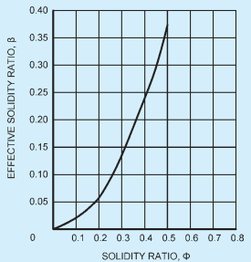
FIG. 6 EFFECTIVE SOLIDITY RATIO, FOR CIRCULAR SECTION MEMBERS
Table 31 Reduction Factor K for Individual Members [Clauses 4.5.4.2.2 and 4.5.4.3.2(a)]
<table><thead><tr><th>Sl No.</th><th>l/b or l/D</th><th>2</th><th>5</th><th>10</th><th>20</th><th>40</th><th>50</th><th>100</th><th></th></tr></thead><tbody><tr><td>(1)</td><td>(2)</td><td>(3)</td><td>(4)</td><td>(5)</td><td>(6)</td><td>(7)</td><td>(8)</td><td>(9)</td><td>(10)</td></tr><tr><td>i)</td><td>Circular cylinder, subcritical flow</td><td>0.58</td><td>0.62</td><td>0.68</td><td>0.74</td><td>0.82</td><td>0.87</td><td>0.98</td><td>1.00</td></tr><tr><td>ii)</td><td>Circular cylinder, supercritical flow (D Vd ≥ 6 m2/ s)</td><td>0.80</td><td>0.80</td><td>0.82</td><td>0.90</td><td>0.98</td><td>0.99</td><td>1.00</td><td>1.00</td></tr><tr><td>iii)</td><td>For plate perpendicular to wind (b Vd ≥ 6 m2/ s)</td><td>0.62</td><td>0.66</td><td>0.69</td><td>0.81</td><td>0.87</td><td>0.90</td><td>0.95</td><td>1.00</td></tr></tbody></table>
##### 4.5.4.3.5 Lattice towers
a) Force coefficient for lattice towers of square or equilateral triangle section with flat-sided members for wind blowing against any face shall be as given in Table 36.
b) For square lattice towers with flat-sided members the maximum load, which occurs when the wind blows into a corner, shall be taken as 1.2 times the load for the wind blowing against a face.
c) For equilateral triangle lattice towers with flat-sided members, the load may be assumed to be constant for any inclination of wind to a face.
d) Force coefficients for lattice towers of square section with circular members, all in the same flow regime, may be as given in Table 37.
e) Force coefficients for lattice towers of equilateral-triangle section with circular members all in the same flow regime may be as given in Table 38.
##### 4.5.4.3.6 Tower appurtenances
The wind loading on tower appurtenances, such as ladders, conduits, lights, elevators, etc, shall be calculated using appropriate net pressure coefficients for these elements. Allowance may be made for shielding effect from other elements.
Vz,H
where
St = Strouhal number,
Vz,H = hourly mean wind speed at height z, and
b = breadth of a structure or structural member normal to the wind direction in the horizontal plane.
a) Circular structures — For structures of circular cross-section:
St = 0.20 for D V z,H less than 6 ~m2/ s, and = 0.25 for D V z,H more than or equal to 6 ~m2/ s.
b) Rectangular structures — For structures of rectangular cross-section:
S t = 0. 1 0
NOTES
1 Significant cross wind motions may be produced by vortex shedding, if the natural frequency of the structure or structural element is equal to the frequency of the vortex shedding within the range of expected wind speeds. In such cases, further analysis should be carried out on the basis of special publications.
2 Unlined welded steel cylindrical structures are prone to excitations by vortex shedding.
3 Intensification of the effects of periodic vortex shedding has been reported in cases where two or more similar structures are located in close proximity, for example at less than 20b apart, where b is the dimension of the structure normal to the wind.
4 The formulae given in 4.7.2.1(a) is valid for infinitely long cylindrical structures. The value of St decreases slowly as the ratio of length to maximum transverse width decreases, the reduction being up to about half the value, if the structure is only three times higher than its width. Vortex shedding need not be considered, if the ratio of length to maximum transverse dimension is less than 2.0.
5.2.8 Diaphragm — It is a horizontal or nearly horizontal structural system (for example, reinforced concrete floors and horizontal bracing systems), which transmits lateral forces to vertical elements connected to it.
5.2.9 Height of Floor ( hi ) — It is the difference in vertical elevations (in metre) of the base of the building and top of floor i of the building.
5.2.10 Height of Building (h) — It is the height of building (in metre) from its base to top of roof level,
a) excluding the height of basement storeys, if basement walls are connected with the ground floor slab or basement walls are fitted between the building columns, but
b) including the height of basement storeys, if basement walls are not connected with the ground floor slab and basement walls are not fitted between the building columns.
In step-back buildings, it shall be taken as the average of heights of all steps from the base, weighted with their corresponding floor areas. And, in buildings founded on hill slopes, it shall be taken as the height of the roof from the top of the highest footing level or pile cap level.
5.2.11 Horizontal Bracing System — It is a horizontal truss system that serves the same function as a diaphragm.
5.2.12 Joints — These are portions of columns that are common to beams/braces and columns, which frame into columns.
5.2.13 Lateral Force Resisting System — It is part of the structural system, and consists of all structural members that resist lateral inertia forces induced in the building during earthquake shaking.
5.2.14 Moment-Resisting Frame — It is an assembly of beams and columns that resist induced and externally applied forces primarily by flexure.
5.2.14.1 Ordinary moment-resisting frame (OMRF)—It is a moment-resisting frame designed and detailed as per relevant good practices [6-1(7)], but not meeting special detailing requirements for ductile behaviour as per good practices [6-1(8)] or [6-1(9)], as applicable.
5.2.14.2 Special moment-resisting frame (SMRF) — It is a moment-resisting frame designed and detailed as per relevant good practices [6-1(7)], and meeting special detailing requirements for ductile behaviour as per good practices [6-1(8)] or [6-1(9)], as applicable.
5.2.15 Number of Storeys (n) — It is the number of levels of a building above the base at which mass is present in substantive amounts. This,
a) excludes the basement storeys, where basement walls are connected with the ground floor deck or fitted between the building columns; and
b) includes the basement storeys, when they are not so connected.
5.2.16 Core Structural Walls, Perimeter Columns, Outriggers and Belt Truss System — It is a structural system comprising a core of structural walls and perimeter columns, resisting the vertical and lateral loads, with
a) the core structural walls connected to select perimeter column element(s) (often termed outrigged columns) by deep beam elements, known as outriggers, at discrete locations along the height of the building; and
b) the outrigged columns connected by deep beam elements (often known as belt truss), typically at the same level as the outrigger elements.
A structure with this structural system has enhanced lateral stiffness, wherein core structural walls and perimeter columns are mobilized to act with each other
through the outriggers, and the perimeter columns themselves through the belt truss. The global lateral stiffness is sensitive to: flexural stiffness of the core element, the flexural stiffness of the outrigger element(s), the axial stiffness of the outrigged column(s), and the flexural stiffness of the outrigger elements connecting the core structural walls to the perimeter columns.
5.2.17 Principal Plan Axes — These are two mutually perpendicular horizontal directions in plan of a building along which the geometry of the building is oriented.
5.2.18 P- Δ Effect — It is the secondary effect on shear forces and bending moments of lateral force resisting elements generated under the action of the vertical loads, interacting with the lateral displacement of building resulting from seismic effects.
5.2.19 RC Structural Wall — It is a wall designed to resist lateral forces acting in its own plane.
5.2.19.1 Ordinary RC structural wall — It is a reinforced concrete (RC) structural wall designed and detailed as per good practice [6-1(10)], but not meeting special detailing requirements for ductile behaviour as per good practice [6-1(8)].
5.2.19.2 Special RC structural wall — It is a RC structural wall designed and detailed in accordance with and meeting special detailing requirements for ductile behaviour, as per good practice [6-1(8)].
5.2.20 Storey — It is the space between two adjacent floors.
5.2.20.1 Soft storey — It is one in which the lateral stiffness is less than that in the storey above. The storey lateral stiffness is the total stiffness of all seismic force resisting elements resisting lateral earthquake shaking effects in the considered direction.
5.2.20.2 Weak storey — It is one in which the storey lateral strength [cumulative design shear strength of all structural members other than that of unreinforced masonry (URM) infills] is less than that in the storey above. The storey lateral strength is the total strength of all seismic force resisting elements sharing the lateral storey shear in the considered direction.
5.2.21 Storey Drift — It is the relative displacement between the floors above and/or below the storey under consideration.
5.2.22 Storey Shear ( Vi ) — It is the sum of design lateral forces at all levels above the storey i under consideration.
5.2.23 Storey Lateral Shear Strength (Si) — It is the total lateral strength of all lateral force resisting
elements in the storey considered in a principal plan direction of the building.
5.2.24 Storey Lateral Translational Stiffness ( Ki ) — It is the total lateral translational stiffness of all lateral force resisting elements in the storey considered in a principal plan direction of the building.
5.2.25 RC Structural Wall Plan Density ( ρsw ) — It is the ratio of the cross-sectional area at the plinth level of RC structural walls resisting the lateral load and the plinth of the building, expressed as a percentage.
a
=
∑Fzz
Fz=Cf,zAzpdG
where
Fz = design peak along wind load on the building/structure at any height z;
Az = effective frontal area of the building/structure at any height z, in m ² ;
Pd = design hourly mean wind pressure corresponding to V z,d and obtained as 0.6 V z,d (N / m²)
Vz,d= design hourly mean wind speed at height z,
in m/s (see 4.4.4);
Cf,z = drag force coefficient of the building/structure corresponding to the area Az;
G = Gust Factor and is given by:
=1+r[gv2Bs(1+ϕ)2+βHsgR2SE]
where
r = roughness factor which is twice the longitudinal turbulence intensity, Ih,i (see 4.4.5);
gv = peak factor for upwind velocity fluctuation
= 3.0 for category 1 and 2 terrains; and
= 4.0 for category 3 and 4 terrains;
Bs = background factor indicating the measure of slowly varying component of fluctuating wind load caused by the lower frequency wind speed variations
=[1+Lh0.26(h−s)2+0.46bsh2]1
where
bsh = average breadth of the building/structure between heights s and h;
Lh = measure of effective turbulence length scale at the height, h, in m;
= 85((h)/(10))0.25 for terrain category 1 to 3, and
= 70((h)/(10))0.25 for terrain category 4
φ = factor to account for the second order turbulence intensity;
=2gvIh,iBs
Ih,i = turbulence intensity at height h in terrain category i;
Hs = height factor for resonance response;
=1+(hs)2
S = size reduction factor given by:
=[1+Vh,d3.5fah][1+Vh,d4fab1
where
b0h = average breadth of the building/structure between 0 and h;
E = spectrum of turbulence in the approaching wind stream
=(1+70.8N2)5/6πN
where
N = effective reduced frequency
=Vh,dfaLh
fa = first mode natural frequency of the building/structure in along wind direction, in Hz;
Vh,d= design hourly mean wind speed at height, h, in m/s (see 4.4.4);
β = damping coefficient of the building/structure (see Table 39); and
gR = peak factor for resonant response.
= √ [2 (3600f a) ]
Table 39Suggested Values of Structural Damping Coefficients (Clause 4.8.2)
Sl No.
Kind of Structure
Damping Coefficient
(1)
(2)
β(3)
i)
Welded steel structures
0.010
ii)
Bolted steel structures/RCC structures
0.020
iii)
Prestressed concrete structures
0.016
4.8.2.1 Peak acceleration in along wind direction
The peak acceleration at the top of the building structure in along wind direction ( x in m/s2) is given by the following equation:
x¨^=(2πfa)2xˉgRrβSE
where
x = mean deflection at the position where the acceleration is required. Other notations are same as given in 9.2.
For computing the peak acceleration in the along wind direction, a mean wind speed at the height of the building /structure, V h corresponding to a 5 year mean return period shall be used. A reduced value of 0.011 is also suggested for the structural damping, ! for reinforced concrete structures.
4.8.3 Across Wind Response
This section gives method for determining equivalent static wind load and base overturning moment in the across wind direction for tall enclosed buildings and towers of rectangular cross-section. Calculation of across wind response is not required for lattice towers.
The across wind design peak base bending moment Mc for enclosed buildings and towers shall be determined as follows:
Mc=0.5ghphbh2(1.06−0.06k)βπCfs
where
gh=
p h = hourly mean wind pressure at height h, in Pa;
b = breadth of the structure normal to the wind, in m;
h = height of the structure, in m;
k = mode shape power exponent for representation of the fundamental mode
shape as represented by:
ψ(z)=(hz)k;and
f c = first mode natural frequency of the building structure in across wind direction, in Hz.
The across wind load distribution on the building/ structure can be obtained from M c using linear distribution of loads as given below:
Fz,c=(h23
where F z , c = across wind load per unit height at height z.
4.8.3.1 Peak acceleration in across wind direction
The peak acceleration at the top of the building structure in across-wind direction ( y in m / s 2 ) with approximately constant mass per unit height shall be determined as follows:
y
5.3General Principles and Design Criteria
5.3.1 General Principles
5.3.1.1 Ground motion
The characteristics (intensity, duration, frequency content, etc) of seismic ground vibrations expected at any site depend on magnitude of earthquake, its focal depth, epicentral distance, characteristics of the path through which the seismic waves travel, and soil strata on which the structure is founded. The random earthquake ground motions, which cause the structure to oscillate, can be resolved in any three mutually perpendicular directions. The predominant direction of ground vibration is usually horizontal.
Effects of earthquake-induced vertical shaking can be significant for overall stability analysis of structures, especially in structures (a) with large spans, and (b) those in which stability is a criterion for design. Reduction in gravity force due to vertical ground motions can be detrimental particularly in prestressed horizontal members, cantilevered members and gravity structures. Hence, special attention shall be paid to effects of vertical ground motion on prestressed or cantilevered beams, girders and slabs.
5.3.1.2 The response of a structure to ground vibrations depends on (a) type of foundation; (b) materials, form, size and mode of construction of structures; and (c) duration and characteristics of ground motion. This Section specifies design forces for structures founded on rocks or soils, which do not settle, liquefy or slide due to loss of strength during earthquake ground vibrations.
5.3.1.3 Actual forces that appear on structures during earthquakes are much higher than the design forces specified in the Section. Ductility arising from inelastic material behaviour with appropriate design and detailing, and overstrength resulting from the additional reserve strength in structures over and above the design strength are relied upon for the deficit in actual and design lateral loads. In other words,
earthquake resistant design as per this Section relies on inelastic behaviour of structures. But, the maximum ductility that can be realized in structures is limited. Therefore, structures shall be designed for at least the minimum design lateral force specified in this Section.
5.3.1.4 Members and connections of reinforced and prestressed concrete structures shall be designed (as per good practices [6-1(11)] such that premature failure does not occur due to shear or bond. Some provisions for appropriate ductile detailing of RC members are given in good practice [6-1(8)]. Members and their connections of steel structures should be so proportioned that high ductility is obtained in the structure, avoiding premature failure due to elastic or inelastic buckling of any type. Some provisions for appropriate ductile detailing of steel members are given in good practice [6-1(9)].
Typical values of the mode shape power exponent, k are as follows:
a) uniform cantilever, k = 1 . 5
b) slender framed structure (moment resisting), k = 0 . 5
c) building with a central core and moment resisting façade, k = 1.0
d) lattice tower decreasing in stiffness with height, or a tower with a large mass at the top, k = 2 . 3
C f s = across wind force spectrum coefficient generalized for a linear mode (see Fig. 10);
! = damping coefficient of the building/structure (see Table 39); and
m 0 = average mass per unit height of the structure, in kg/m.
4.8.4 Combination of Along Wind and Across Wind Load Effects
The along wind and across wind loads have to be applied simultaneously on the building/structure during design.
5.3.1.5 The soil-structure interaction refers to effects of the flexibility of supporting soil-foundation system on the response of structure. Soil-structure interaction may not be considered in the seismic analysis of structures supported on rock or rock-like material at shallow depth.
5.3.1.6 Equipment and other systems, which are supported at various floor levels of a structure, will be subjected to different motions at their support points. In such cases, it may be necessary to obtain floor response spectra for design of equipment and its supports. For details, reference may be made to good practice [6-1(12)].
5.3.1.7 Additions to existing structures
Additions shall be made to existing structures only as follows:
a) An addition that is structurally independent from an existing structure shall be designed and constructed in accordance with the seismic requirements for new structures.
b) An addition that is structurally connected to an existing structure shall be designed and constructed such that the entire structure conforms to the seismic force resistance requirements for new structures, unless the following three conditions are complied with:
Addition shall comply with the requirements for new structures,
Addition shall not increase the seismic forces in any structural element of the existing structures by more than 5 percent, unless the capacity of the element subject to the increased force is
still in compliance with this Section, and
Addition shall not decrease the seismic resistance of any structural element of the existing structure unless reduced resistance is equal to or greater than that required for new structures.
5.3.1.8 Change in occupancy
When a change of occupancy results in a structure being reclassified to a higher importance factor (I), the structure shall conform to seismic requirements laid down for new structures with the higher importance factor.
5.3.2 Assumptions
The following assumptions shall be made in the earthquake-resistant design of structures:
a) Earthquake ground motions are complex and irregular, consisting of several frequencies and of varying amplitudes each lasting for a small duration. Therefore, usually, resonance of the type as visualized under steady-state sinusoidal excitations will not occur, as it would need time to build up such amplitudes. But, there are exceptions where resonance-like conditions have been seen to occur between long distance waves and tall structures founded on deep soft soils.
b) Earthquake is not likely to occur simultaneously with high wind, maximum flood or maximum sea waves.
c) The values of elastic modulus of materials, wherever required, will be taken as for static analysis, unless more definite values are available for use in dynamic conditions {see good practice [6-1(13)]}.
5.3.3 Load Combinations and Increase in Permissible Stresses
5.3.3.1 Load combinations
The load combinations shall be considered as specified in respective standards due to all load effects mentioned therein. In addition, those specified in this standard shall be applicable, which include earthquake effects.
5.3.3.1.1 Even when load combinations that do not contain earthquake effects, indicate larger demands than combinations including them, the provisions shall be adopted related to design, ductile detailing and construction relevant for earthquake conditions, which are given in this Section, good practice [6-1(8)] and good practice [6-1(9)].
5.3.3.2 Design horizontal earthquake load
5.3.3.2.1 When lateral load resisting elements are oriented along two mutually orthogonal horizontal directions, structure shall be designed for effects due to full design earthquake load in one horizontal direction at a time, and not in both directions simultaneously.
5.3.3.2.2 When lateral load resisting elements are not oriented along mutually orthogonal horizontal directions [as per 5.4.1 and Sl No. (v) of Table 44], structure shall be designed for the simultaneous effects due to full design earthquake load in one horizontal direction plus 30 percent of design earthquake load along the other horizontal direction. Thus, structure should be designed for the following sets of combinations of earthquake effects:
a)b)±ELX±0.3ELY,and±0.3EL
where X and Y are two orthogonal horizontal plan directions. Thus, EL in the load combinations shall be replaced by (ELX ± 0.3 ELY) or (ELY ± 0.3 ELX) . Hence, the sets of load combinations to be considered shall be as given below:
1.2[DL + IL ± (ELX ± 0.3ELY)] and
2 [ D L + I L ± (E L Y ± 0. 3 E L X) ];
1.5[DL± (ELX± 0.3ELY)] and
5 [ D L ± (E L Y ± 0. 3 E L X) ]; and
0.9DL± 1.5(ELX± 0.3ELY) and
9 D L ± 1. 5 (E L Y ± 0. 3 E L X).
5.3.3.3 Design vertical earthquake effects
5.3.3.3.1 Effects due to vertical earthquake shaking shall be considered when any of the following conditions apply:
a) Structure is located in Seismic Zone IV or V;
b) Structure has vertical or plan irregularities;
c) Structure is rested on soft soil;
d) Bridges;
e) Structure has long spans; or
f) Structure has large horizontal overhangs of structural members or sub-systems.
5.3.3.3.2 When effects due to vertical earthquake shaking are to be considered, the design vertical force shall be calculated for vertical ground motion as detailed in 5.3.4.6.
5.3.3.3.3 Where both horizontal and vertical seismic
forces are taken into account, load combination specified in 5.3.3.4 shall be considered.
5.3.3.4 Combinations to account for three directional earthquake ground shaking
5.3.3.4.1 When responses from the three earthquake components are to be considered, the responses due to each component may be combined using the assumption that when the maximum response from one component occurs, the responses from the other two components are 30 percent each of their maximum. All possible combinations of three components ( ELX , ELY and ELZ ) including variations in sign (plus or minus) shall be considered. Thus, the structure should be designed for the following sets of combinations of earthquake load effects:
5.3.4 Design Acceleration Spectrum
5.3.4.1 For the purpose of determining design seismic force, the country is classified into four seismic zones as shown in Fig. 11.
Table 40Percentage Increase in Net Bearing Pressure and Skin Friction of Soils (Clause 5.3.3.5.2)
Sl No.
Soil Type
Percentage Increase Allowable
(1)
(2)
(3)
i)
Type A: Rock or hard soils
50
ii)
Type B: Medium or stiff soils
25
iii)
Type C: Soft soils
0
NOTES
1 The net bearing pressure shall be determined in accordance with good practice [6-1(15)] or accepted standards [6-1(16)]
2 Only corrected values of N shall be used.
3 If any increase in net bearing pressure has already been permitted for forces other than seismic forces, the total increase in allowable bearing pressure, when seismic force is also included, shall not exceed the limits specified above.
4 The desirable minimum corrected field values of N shall be as specified below:
Seismic Zone
Depth (m) belowGround Level
N Values
Remarks
III, IV and V
≤ 5 ≥ 10
1525
For values of depths between 5 m and 10 m, linear interpolation is recommended
II
≤ 5 ≥ 10
1020
If soils of lower N values are encountered than those specified in the table above, then suitable ground improvement techniques shall be adopted to achieve these values. Alternately, deep pile foundations should be used, which are anchored in stronger strata, underlying the soil layers that do not meet the requirement.
5 Piles should be designed for lateral loads neglecting lateral resistance of those soil layers (if any), which are liable to liquefy.
6 Accepted standard [6-1(17)] may be referred for soil notation, and corrected N values shall be determined by applying correction
factor CN for effective overburden pressure σ'vo using relation N = CN N₁, where CN = √Ps / σ'vo ≤ 1.7, Ps is the atmospheric pressure, and N₁ is the uncorrected SPT value for soil.
7 While using this table, the value of N to be considered shall be determined as below:
a) Isolated footings — Weighted average of N of soil layers from depth of founding, to depth of founding plus twice the breadth of footing;
b) Raft foundations — Weighted average of N of soil layers from deptb of founding, to depth of founding plus twice the breadth of raft;
c) Pile foundation — Weighted average of N of soil layers from depth of bottom tip of pile, to depth of bottom tip of pile plus twice the diameter of pile;
d) Group pile foundation — Weighted average of N of soil layers from depth of bottom tip of pile group, to depth of bottom tip of pile group plus twice the width of pile group; and
e) Well foundation — Weighted average of N of soil layers from depth of bottom tip of well, to depth of bottom tip of well plus twice the width of well.
Table 41Classification of Types of Soils for Determining Percentage Increase in Net Bearing Pressure and Skin Friction (Clause 5.3.3.5.2)
Sl No.(1)
Soil Type(2)
Remarks(3)
i)
Type ARock or hard soils
Well graded gravel (GW) or well graded sand (SW) both with less than 5 percent passing 75 μm sieve (Fines)Well graded gravel - sand mixtures with or without fines (GW-SW)Poorly-graded sand (SP) or Clayey sand (SC), all having N above 30 stiff to hard clays having N above 30, where N is corrected standard penetration test value
ii)
Type BMedium or stiff soils
Poorly graded sands or poorly graded sands with gravel (SP) with little or no fines having N between 10 and 30Stiff to medium stiff fine-grained soils, like silts of low compressibility (ML) or clays of low compressibility (CL) baving N between 10 and 30
iii)
Type CSoft soils
All soft soils other than SP with N<10. The various possible soils are:a) Silts of intermediate compressibility (MI);b) Silts of high compressibility (MH);c) Clays of intermediate compressibility (CI);d) Clays of high compressibility (CH);e) Silts and clays of intermediate to high compressibility (MI-MH or CI-CH);f) Silt with clay of intermediate compressibility (MI-CI); andg) Silt with clay of high compressibility (MH-CH).
iv)
Type DUnstable, collapsible, liquefiable soils
Requires site-specific study and special treatment according to site condition (see 5.3.3.5.3)
Based upon Survey of India Political map printed in 2002.
The territorial waters of India extend into the sea to a distance of twelve nautical miles measured from the appropriate baseline.
The interstate boundaries between Arunachal Pradesh, Assam and Meghalaya shown on this map are as interpreted from the North-Eastern Areas (Reorganization) Act, 1971, but have yet to be verified.
The state boundaries between Uttarakhand & Uttar Pradesh, Bihar & Jharkhand, and Chhattisgarh & Madhya Pradesh have not been verified by the Governments concerned.
The administrative headquarters of Chandigarh, Haryana and Punjab are at Chandigarh.
The external boundaries and coastlines of India agree with the Record/Master Copy certified by Survey of India.
The responsibility for the correctness of internal details rests with the publisher.
NOTE – Towns falling at the boundary of zones demarcation line between two zones shall be considered in higher zone.
FIG. 11 SEISMIC ZONES OF INDIA
5.3.4.2 The design horizontal seismic coefficient Ah for a structure shall be determined by:
Ah=(IR
where
Z = seismic zone factor given in Table 42. Zone factor for some important towns are given at Annex K;
I = importance factor given in good practice [6-1(18)] for the corresponding structures; when not specified, the minimum values of I shall be,
a) 1.5 for critical and lifeline structures;
b) 1.2 for business continuity structures; and
c) 1.0 for the rest.
R = response reduction factor given in good practice [6-1(18)] for the corresponding structures; and
( S a g )= design acceleration coefficient for different soil types, normalized with peak ground acceleration,
corresponding to natural period T of structure (considering soil-structure interaction, if required). It shall be as given in good practice [6-1(18)] for the corresponding structures; when not specified, it shall be taken as that corresponding to 5 percent damping, given by expressions below:
a) For use in equivalent static method (see Fig. 12A):
b) For use in response spectrum method (see Fig. 12B):
5.3.4.2.1 For determining the correct spectrum to be used in the estimate of Sa / g, the type of soil on which the structure is placed shall be identified by the classification given in Table 43, as:
a) Soil type I — Rock or hard soils;
b) Soil type II — Medium or stiff soils; and
c) Soil type III — Soft soils.
In Table 43, the value of N to be used shall be the weighted average of N of soil layers from the existing ground level, to 30m below the existing ground level; here, the N values of individual layers shall be the corrected values.
5.3.4.3 Effects of design earthquake loads applied on structures can be considered in two ways, namely:
a) Equivalent static method, and
b) Dynamic analysis method.
In turn, dynamic analysis can be performed in three ways, namely:
Response spectrum method,
Modal time history method, and
Time history method.
In this Section, equivalent static method, response spectrum method and time history method are adopted. Equivalent static method may be used for analysis of regular structures with approximate natural period Ta less than 0.4 s.
5.3.4.3.1 For structural analysis, the moment of inertia shall be taken as:
a) In RC and masonry structures: 70 percent of Igross of columns, and 35 percent of Igross of beams; and
b) In steel structures: Igross of both beams and columns.
5.3.4.4 Where a number of modes are to be considered in response spectrum method, Ah as defined in 5.3.4.2 for each mode k shall be determined using natural period Tk of oscillation of that mode.
Table 43Classification of Types of Soils for Determining the Spectrum to be Used to Estimate Design Earthquake Force (Clause 5.3.4.2.1)
Sl No.
Soil Type
Remarks
(1)
(2)
(3)
i)
IRock or Hard soils
a) Well graded gravel (GW) or well graded sand (SW) both with less than 5 percent passing 75 μm sieve (Fines)b) Well graded gravel-sand mixtures with or without fines (GW-SW)c) Poorly graded sand (SP) or clayey sand (SC), all having N above 30d) Stiff to hard clays having N above 30, where N is standard penetration test value
ii)
IIMedium or Stiff soils
a) Poorly graded sands or poorly graded sands with gravel (SP) with little or no fines having N between 10 and 30b) Stiff to medium stiff fine-grained soils, like silts of low compressibility (ML) or clays of low compressibility (CL) having N between 10 and 30
iii)
IIISoft soils
All soft soils other than SP with N<10.The various possible soils are:a) Silts of intermediate compressibility (MI)b) Silts of high compressibility (MH);c) Clays of intermediate compressibility (CI)d) Clays of high compressibility (CH);e) Silts and clays of intermediate to high compressibility (MI-MH or CI-CH)d) Silt with clay of intermediate compressibility (MI-CI)g) Silt with clay of high compressibility (MH-CH).
5.3.4.5 For underground structures and buildings whose base is located at depths of 30m or more, Ah at the base shall be taken as half the value obtained from 5.3.4.2. This reduced value shall be used only for estimating inertia effects due to masses at the corresponding levels below the ground; the inertia effects for the above ground portion of the building shall be estimated based on the unreduced value of Ah. For estimating inertia effects due to masses of structures and foundations placed between the ground level and 30m depth, the design horizontal acceleration spectrum value shall be linearly interpolated between Ah and 0.5Ah where Ah is as specified in 5.3.4.2.
5.3.4.6 The design seismic acceleration spectral value Av for vertical motions shall be taken as:
The value of Sa / g shall be based on natural period T corresponding to the first vertical mode of oscillation, using 5.3.4.2.
5.3.4.7 When design acceleration spectrum is developed specific to a project site, the same may be used for design of structures of the project. In such cases, effects of the site-specific spectrum shall not be less than those arising out of the design spectrum specified in this Section.
where X and Y are orthogonal plan directions and Z vertical direction. Thus, EL in the above referred load combinations shall be replaced by (ELX ± 0.3 ELY ± 0.3 ELZ), (ELY ± 0.3 ELZ ± 0.3 ELX) or (ELZ ± 0.3 ELX ± 0.3 ELY). This implies that the sets of load combinations involving earthquake effects to be considered shall be as given below:
1.2[DL + IL± (ELx± 0.3ELy± 0.3ELz)] and
2 [ DL + IL ± (E L Y ± 0. 3 E L X ± 0. 3 E L Z) ];
5.3.3.4.2 As an alternative to the procedure in 5.3.3.4.1, the net response (EL) due to the combined effect of the three components can be obtained by:
E L = √ (E L X) ² + (E L Y) ² + (E L Z) ²
Caution may be exercised on loss of sign especially of the axial force, shear force and bending moment quantities, when this procedure is used; it can lead to grossly uneconomical design of structures.
5.3.3.4.3 Procedure for combining shaking effects given by 5.3.3.4.1 and 5.3.3.4.2 apply to the same response quantity (say, bending moment in a column about its major axis, or storey shear force in a frame) due to different components of the ground motion.
5.3.3.4.4 When components corresponding to only two ground motion components (say one horizontal and one vertical, or only two horizontal) are combined, the equations in 5.3.3.4.1 and 5.3.3.4.2 should be modified by deleting the term representing the response due to the component of motion not being considered.
5.3.3.5 Increase in net pressure on soils in design of foundations
5.3.3.5.1 In the design of foundations, unfactored loads shall be combined in line with good practices [6-1(14)], while assessing the bearing pressure in soils.
5.3.3.5.2 When earthquake forces are included, net bearing pressure in soils can be increased as per Table 40, depending on type of foundation and type of soil. For determining the type of soil for this purpose, soils shall be classified in four types as given in Table 41. In soft soils, no increase shall be applied in bearing pressure, because settlements cannot be restricted by increasing bearing pressure.
5.3.3.5.3 In soil deposits consisting of submerged loose sands and soils falling under classification SP with corrected standard penetration test values N, less than 15 in Seismic Zones III, IV and V, and less than 10 in Seismic Zone II, the shaking caused by earthquake ground motion may cause liquefaction or excessive total and differential settlements. Such sites should be avoided preferably for locating new structures, and should be avoided for locating structures of important projects. Otherwise, settlements need to be investigated, and appropriate methods adopted of compaction or stabilization to achieve N values indicated in Note 4 of Table 40. Alternatively, deep pile foundations may be adopted and anchored at depths well below the underlying soil layers, which are likely to liquefy or undergo excessive settlements.
Also, marine clay layers and other sensitive clay layers are known to liquefy, undergo excessive settlements or even collapse, owing to low shear strength of the said soil; such soils will need special treatment according to site condition (see Table 41).
A simplified method is given in Annex J, for evaluation of liquefaction potential.
)
(2Z)(gSa)
gSa=⎩⎨⎧For rocky or hard soil sitesFor medium stiff soil sitesFor soft soil sites⎩⎨⎧2.5
Av=⎩⎨⎧(IR)(32×2Z)(2.5)(IR)(32(IR)(32(IR)(32For buildings governed by IS 1893 (Part 1)For liquid retaining tanks governed by IS 1893 (Part 2)For bridges governed by IS 1893 (Part 3)For industrial structures governed by IS 1893 (Part 4)