The basic module is to be adopted. After adopting this,
further work is necessary to outline suitable range of multi-modules with greater increments, often referred to as preferred increments. A set of rules as detailed below would be adequate for meeting the requirements of conventional and prefabricated construction.
These rules relate to the following basic elements:
a) The planning grid in both directions of the horizontal plan shall be:
15 M for industrial buildings,
3 M for other buildings.
The centre lines of load bearing walls should preferably coincide with the gridlines.
b) The planning module in the vertical direction shall be 2 M for industrial buildings and 1 M for other buildings.
c) Preferred increments for sill heights, doors, windows and other fenestration shall be 1 M.
d) In the case of internal columns, the grid lines shall coincide with the centre lines of columns. In case of external columns and columns near the lift and stair wells, the grid lines shall coincide with centre lines of the column in the topmost storey.
4.2 Architectural Treatment and Finishes
Treatment and finishes have to be specified keeping in view the requirements of protection, function and aesthetics of internal and external spaces and surfaces.
While deciding the type of architectural treatment and finishes for prefabricated buildings, the following points should be kept in view:
a) Suitability for mass production techniques;
b) Recognition of the constraints imposed by the level of workmanship available;
c) Possibility of using different types of finishes;
d) Use of finishes and architectural treatment for the creation of a particular architectural character in individual buildings and in groups of buildings by the use of colour, texture, projections and recesses on surfaces, etc;
e) Incorporation of structural elements like joists, columns, beams, etc, as architectural features and the treatment of these for better overall performance and appearance;
f) Satisfactory finishing of surfaces; and
g) Use of light weight materials to effect economy in the structural system.
Some of the acceptable methods of finishes integral with the precasting are:
a) Concrete surface moulded to design; shape;
b) Laid-on finishing tiles fixed during casting;
c) Finishes obtained by washing, tooling, grinding, grooving of hardened concrete;
d) Exposed aggregates; and
e) Other integral finishes.
2Terminology
2.1 For the purpose of this sub-section, the following definitions shall apply.
2.1.1 Authority Having Jurisdiction — The Authority which has been created by a statute and which, for the purpose of administering the Code/Part, may authorize a committee or an official or an agency to act on its behalf; hereinafter called the ‘Authority’.
2.1.2 Basic Module — The fundamental module used in modular co-ordination, the size of which is selected for general application to building and its components.
NOTE — The value of the basic module has been chosen as 100 mm for the maximum flexibility and convenience. The symbol for the basic module is M.
2.1.3 Cellular Concrete — The material consisting of an inorganic binder (such as, lime or cement or both) in combination with a finely ground material containing siliceous material (such as sand), gas generating material (for example, aluminium powder), water and harmless additives (optional); and steam cured under high pressure in autoclaves.
2.1.4 Components — A building product formed as a distinct unit having specified sizes in three dimensions.
2.1.5 Composite Members — Structural members comprising prefabricated structural units of steel, prestressed concrete or reinforced concrete and cast in-situ concrete connected together in such a manner that they act monolithically.
2.1.6 Increments — Difference between two homologous dimensions of components of successive sizes.
2.1.7 Light Weight Concrete — Concrete of substantially lower unit weight than that made from gravel or crushed stone.
2.1.8 Module — A unit of size used in dimensional co-ordination.
2.1.9 Modular Co-ordination — Dimensional
co-ordination employing the basic module or a multi-module.
NOTE — The purposes of modular co-ordination are:
a) to reduce the variety of component sizes produced, and
b) to allow the building designer greater flexibility in the arrangement of components.
2.1.10 Modular Grid — A rectangular coordinate reference system in which the distance between consecutive lines is the basic module or a multi-module. This multi-module may differ for each of the two dimensions of the grid.
2.1.11 Multi-module — A module whose size is a selected multiple of the basic module.
2.1.12 Prefabricate — To fabricate components or assembled units prior to erection or installation in a building.
5
2.1.13 Prefabricated Building — The partly/fully assembled and erected building, of which the structural parts consist of prefabricated individual units or assemblies using ordinary or controlled materials, including service facilities; and in which the service equipment may be either prefabricated or constructed in-situ.
2.1.14 Sandwich Concrete Panels — Panels made by sandwiching an insulation material between two layers of reinforced concrete to act as insulation for concrete panels.
2.1.15 Self Compacting Concrete — Concrete that is able to flow under its own weight and completely fill the voids within the formwork, even in the presence of dense reinforcement without any vibration, whilst maintaining homogeneity without segregation.
2.1.16 Shear Connectors — Structural elements, such as anchors, studs, channels and spirals, intended to transmit the horizontal shear between the prefabricated member and the cast in-situ concrete and also to prevent vertical separation at the interface.
2.1.17 System — It is a particular method of construction of buildings with certain order and discipline using the prefabricated components, tunnel form or large panel shutters which are inter-related in functions and are produced based on a set of instructions.
2.1.18 Unit — Building material formed as a simple article with all three dimensions specified, complete
in itself but intended to be part of a compound unit or complete building. Examples are brick, block, tile, etc.
1Scope
This sub-section gives recommendations regarding modular planning, component sizes, prefabrication systems, design considerations, joints and manufacture, storage, transport and erection of prefabricated concrete elements for use in buildings and such related requirements for prefabricated concrete.
5Components
5.1 The preferred dimensions of precast elements shall be as follows:
a) Flooring and Roofing Scheme — Precast slabs or other precast structural flooring units:
Length — Nominal length shall be in multiples of 1 M;
Width — Nominal width shall be in multiples of 0.5 M; and
Overall Thickness — Overall thickness shall be in multiples of 0.1 M.
b) Beams
Length — Nominal length shall be in multiples of 1 M;
Width — Nominal width shall be in multiples of 0.1 M; and
Overall Depth — Overall depth of the floor zone shall be in multiples of 0.1 M.
c) Columns
Height — Height of columns for industrial and other building 1 M; and
Lateral Dimensions — Overall lateral dimension or diameter of columns shall be in multiples of 0.1 M.
d) Walls
Thickness — The nominal thickness of walls shall be in multiples of 0.1 M.
e) Staircase
Width — Nominal width shall be in multiples of 1 M.
f) Lintels
Length — Nominal length shall be in multiples of 1 M;
Width — Nominal width shall be in multiples of 0.1 M; and
Depth — Nominal depth shall be in multiples of 0.1 M.
g) Sunshades/Chajja Projections
Length — Nominal length shall be in multiples of 1 M.
Projection — Nominal length shall be in multiples of 0.5 M.
5.2 Casting Tolerances of Precast Components
(1) (2) (3)
5
± 5 mm or ± 0.1 percent whichever is 2, 3, 8 greater
± 0.1 percent subject to maximum 4 of + 5 - 1 0 mm
± 2 mm for length below and up to 5 500 mm
± 5 mm for length over 500 mm 5
± 3 mm 1
± 3 mm or 0.1 percent whichever is 2, 8 greater
± 2 mm up to 300 mm wide 4 4
± 3 mm greater than 300 mm wide
± 2 mm 3, 7
± 4 mm 6, 9, 10
iii) Straightness/Bow
± 5 mm or 1/750 of length whichever 2, 4, 8 is greater
± 3 mm 1, 5
± 2 mm 7
iv) Squareness
When considering the squareness of the corner, the longer of two adjacent sides being checked shall be taken as the base line.
The shorter side shall not vary in 2, 5, 8 length from the perpendicular by more than 5 mm
The shorter side shall not vary in 1, 7 length from the perpendicular by more than 3 mm
The shorter side shall not be out of square line for more than + 2 - 5 mm
v) Twist
Any corner shall not be more than the tolerance given below from the plane containing the other three corners:
± 5 mm (Up to 600 mm in width and 2, 8 up to 6 m in length)
± 10 mm (Over 600 mm in width and for any length)
± 1/1 500 of dimension of ± 5 mm 4 whichever is less
(1)
(2)
(3)
±3 mm
1
±1 mm
7
vi) Flatness
The maximum deviation from 1.5 m straight edge placed in any position on a nominal plane surface shall not
± 5 mm 2, 8
± 3 mm 4
± 2 mm 1, 7
± 4 or maximum of 0.1 percent 5 length
NOTES — Key for product reference
1 Channel unit
2 Ribbed slab unit/hollow slab
3 Waffle unit
4 Large panel prefabrication
5 Cellular concrete floor/roof slabs
6 Prefabricated brick panel
7 Precast planks
8 Ribbed/plain wall panel
9 Column
10 Step unit
Part 6 Section 7APrefabricated Concrete
c) A detailed clause on design requirements for safety of prefabricated buildings against progressive clause has been included.
d) A clause on sampling procedure has been added for testing of components.
e) List of Indian Standards referred as good practice has been updated, specially in view of formulation of a large number of new Indian Standards on partially prefabricated components.
All standards cross-referred to in the main text of the sub-section, are subject to revision. The parties to agreement based on this sub-section are encouraged to investigate the possibility of applying the most recent editions of the standard.
6.3Prefabrication Systems
The system of prefabricated construction depends on the extent of the use of prefabricated components, their materials, sizes and the technique adopted for their manufacture and use in building.
6.3.1 Types of Prefabrication Components
The prefabricated concrete components such as those given below may be used which shall be in accordance with Part 5 ‘Building Materials’ and the accepted standards [6-7A(1)], where available:
j) Precast planks and joists for flooring and roofing,
k) Precast joists and trussed girders,
m) Light weight/cellular concrete slabs,
n) Precast lintel and chajjas,
p) Large panel prefabricates,
q) Reinforced/Prestressed concrete trusses,
r) Reinforced/Prestressed roof purlins,
s) Precast concrete L-panel unit,
t) Prefabricated brick panel unit,
u) Prefabricated sandwich concrete panel, and
v) Precast foundation.
There may be other types of components which may be used with the approval of the Authority.
NOTE — The elements may be cast at the site or off the site.
6.3.2 There are two categories of open prefab system depending on the extent of prefabrication used in the construction as given in 6.3.2.1 and 6.3.2.2.
6.3.2.1 Partial prefabrication system
This system basically uses precast roofing and flooring components and other minor elements like lintels, CHAJJAS, kitchen sills in conventional building construction. The structural system could be in the form of in-situ framework or load bearing walls.
6.3.2.2 Full prefabrication system
In this system almost all the structural components are prefabricated. The filler walls may be of brick/block masonry or of any other locally available material.
6.3.3 Large Panel Prefabrication System
This system is based on the use of large prefab components. The components used are precast concrete large panels for walls, floors, roofs, balconies, staircases, etc. The casting of the components could be at the site or off the site.
Depending upon the extent of prefabrication, this system can also lend itself to partial prefab system and full prefab system.
Structural scheme with precast large panel walls can be classified as given in 6.3.3.1 to 6.3.3.3.
6.3.3.1 Precast Walls
6.3.3.1.1 Based on the structural functions of the walls, the precast walls may be classified as:
a) load bearing walls,
b) non-load bearing walls, and
c) shear walls.
6.3.3.1.2 Based on construction, the precast walls may be classified as:
a) Homogeneous walls — which could be solid, hollow or ribbed; and
b) Non-homogeneous walls — these could be composite or sandwich panels.
6.3.3.1.3 Based on their locations and functional requirements the precast walls may also classified as:
a) external walls, which may be load bearing or non-load bearing depending upon the lay-out; these are usually non-homogeneous walls of sandwiched type to impart better thermal comforts; and
b) internal walls providing resistance against vertical loads, horizontal loads, fire, etc; these are normally homogeneous walls.
6.3.3.2 Precast floors
6.3.3.2.1 Depending upon the composition of units, precast flooring units may be homogeneous or non-homogeneous.
a) Homogeneous floors may be solid slabs, cored slabs, ribbed or waffle slabs.
b) Non-homogeneous floors may be multi-layered ones with combinations of light weight concrete or reinforced/prestressed concrete, with filler blocks.
6.3.3.2.2 Depending upon the way the loads are transferred, the precast floors may be classified as one way or two way systems:
a) One way system transfers loads to supporting members in one direction only. The precast
elements which come under this category are channel slabs, hollow core slabs, channels and ties system, light weight/cellular concrete slabs, etc.
b) Two way systems transfer loads in both the directions imparting loads on the four edges. The precast elements under this category are room sized panels, two way ribbed or waffle slab systems, etc.
6.3.3.3 Staircase systems
Staircase system may consist of single flights with inbuilt risers and treads in the element. The flights are normally unidirectional transferring the loads to supporting landing slabs or load bearing walls.
6.3.4 Box Type Construction
In this system, room size units are prefabricated and erected at site. Toilet and kitchen blocks could also be similarly prefabricated and erected at site.
NOTE — This system derives its stability and stiffness from the box units which are formed by four adjacent walls. Walls are jointed to make rigid connections among themselves. The box unit rests on foundation which may be of conventional type or precast type.
6.5Design Requirements for Safety Against Progressive Collapse
6.5.1 Prefabricated buildings shall be designed with proper structural integrity to avoid situations where damage to small areas of a structure or failure of single elements may lead to collapse of major parts of the structure.
The following precaution may generally provide adequate structural integrity:
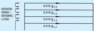
a) All buildings should be capable of safely resisting the minimum horizontal load of 1.5 percent of characteristic dead load applied at each floor or roof level simultaneously (see Fig. 1).
9 κ = Characteristic dead load
FIG. 1 HORIZONTAL LOADS
b) All buildings are provided with effective horizontal ties
Around the periphery
Internally (in both directions)
To columns and walls
c) Vertical ties for buildings of five or more storeys.
In proportioning the ties, it may be assumed that no other forces are acting and the reinforcement is acting at its characteristic strength.
Normal procedure may be to design the structure for the usual loads and then carry out a check for the tie forces.
6.5.2 Continuity and Anchorage of Ties
Bars shall be lapped, welded or mechanically joined as in accordance with Part 6 ‘Structural Design, Section 5 Plain, Reinforced and Prestressed Concrete: 5A Plain and Reinforced Concrete’.
6.5.3 Design of Ties
6.5.3.1 Peripheral ties
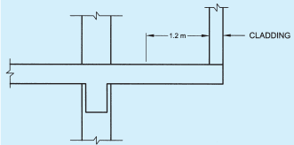
At each floor and roof level an effectively continuous tie should be provided within 1.2 m of the edge of the building or within the perimeter wall (see Fig. 2).
The tie should be capable to resisting a tensile force of F t equal to 60 kN or (20 + 4N) kN whichever is less, where N is the number of storeys (including basement)
NOTE — If there are cantilever slabs, supporting external cladding, projecting in front of the columns and these are more than 1.2 m, than the peripheral tie shall go in the slab.
FIG. 2 POSITION FOR PERIPHERAL TIE
6.5.3.2 Internal ties
These are to be provided at each floor and roof level in two directions approximately at right angles. Ties should be effectively continuous throughout their length and be anchored to the peripheral tie at both ends, unless continuing as horizontal ties to columns or walls (see Fig. 3). The tensile strength, in kN/m width shall be the greater of
7.5(gk+q
6.5.3.3 Horizontal ties to column and wall
All external load-bearing members such as columns and walls should be anchored or tied horizontally into the structure at each floor and roof level. The design force for the tie is to be greater of:
a) 2 F t kN or l s × F t / 2 . 5 k N whichever is less for a column or for each metre length if there is a wall l s is the floor to ceiling height in metres.
b) 3 percent of the total ultimate vertical load in the column or wall at that level.
For corner columns, this tie force should be provided in each of two directions approximately at right angles.
6.5.3.4 Vertical ties (for buildings of five or more storeys)
Each column and each wall carrying vertical load should be tied continuously from the foundation to the roof level. The reinforcement provided is required only to resist a tensile force equal to the maximum design ultimate load (dead and imposed) received from any one storey.
In situation where provision of vertical ties cannot be done, the element should be considered to be removed and the surrounding members designed to bridge the gap.
6.5.4 Key Elements
For buildings of five or more storeys, the layout should be checked to identify key elements. A key element is such that its failure would cause the collapse of more than a limited area close to it.
The limited area defined above may be taken equal to 70 m2 or 15 percent of the area of the storey whichever is lesser.
If key elements exists, it is preferable to modify the layout so that the key element is avoided.
6.4Design Considerations
The precast structure should be analyzed as a monolithic one and the joints in them designed to take the forces of an equivalent discrete system. Resistance to horizontal loading shall be provided by having appropriate moment and shear resisting joints or placing shear walls (in diaphragm braced frame type of construction) in two directions at right angles or otherwise. No account is to be taken of rotational stiffness, if any, of the floor-wall joint in case of precast bearing wall buildings. The individual components shall be designed, taking into consideration the appropriate end conditions and loads at various stages of construction. The components of the structure shall be designed for loads in accordance with Part 6 ‘Structural Design, Section 1 Loads, Forces and Effects’. In addition members shall be designed for handling, erection and impact loads that might be expected during handling and erection.
6.4.1 In some conventional forms of construction, experience has shown that the structures are capable of safely sustaining abnormal conditions of loading and remaining stable after the removal of primary structural members. It has been shown that some forms of building structure and particularly some industrialized large panel systems have little reserve strength to resist forces not specifically catered for in the design. In the light of this, therefore, recommendations made in 6.4.2 to 6.4.9 should be kept in mind for ensuring stability of such structure.
6.4.2 Adequate buttressing of external wall panels is important since these elements are not fully restrained on both sides by floor panels. Adequate design precautions may be taken by the designer. Experience shows that the external wall panel connections are the weakest points of a precast panel building.
6.4.3 It is equally important to provide restraint to all load bearing elements at the corners of the building. These elements and the external ends of cross-wall units should be stiffened either by introducing columns as connecting units or by jointing them to non-structural wall units which in emergency may support the load. Jointing of these units should be done bearing in mind the need for load support in an emergency.
6.4.4 In prefabricated construction, the possibility of gas or other explosions which can remove primary structural elements leading to progressive collapse of the structure shall be taken into account. It is, therefore, necessary to consider the possibility of progressive collapse in which the failure or displacement of one element of a structure causes the failure or displacement of another element and results in the partial or total collapse of the building.
6.4.5 Provision in the design to reduce the probability of progressive collapse is essential in buildings of over six storeys and is of relatively higher priority than for buildings of lower height.
6.4.6 It is necessary to ensure that any local damage to a structure does not spread to other parts of the structure remote from the point of mishap and that the overall stability is not impaired, but it may not be necessary to stiffen all parts of the structure against local damage or collapse in the immediate vicinity of a mishap, unless the design briefs specifically requires this to be done.
6.4.7 Additional protection may be required in respect of damage from vehicles; further, it is necessary to consider the effect of damage to or displacement of a load-bearing member by an uncontrolled vehicle. It is strongly recommended that important structural members are adequately protected by concrete kerbs or similar method.
6.4.8 In all aspects of erection that affect structural design, it is essential that the designer should maintain a close liaison with the builder/contractor regarding the erection procedures to be followed.
6.4.9 Failures that have occurred during construction appear to be of two types. The first of these is the packof-cards type of collapse in which the absence of restraining elements, such as partitions, cladding or shear walls, means that the structure is not stable during the construction period. The second is the situation in
which one element falls during erection and lands on an element below. The connections of the lower element then give way under the loading, both static and dynamic, and a chain reaction of further collapse is set up.
6.4.9.1 A precaution against the first form of failure is that the overall stability of a building shall be considered in all its erection stages as well as in its completed state. All joints that may be required to resist moments and shears during the erection stage only, shall be designed with these in mind. Temporary works required to provide stability during construction shall be designed carefully.
6.4.9.2 To guard against the second form of failure, that is, the dropping of a unit during erection, particular attention shall be given to the details of all pre-formed units and their seatings to ensure that they are sufficiently robust to withstand the maximum stresses that can arise from site conditions. Precast concrete construction generally shall be capable of withstanding the impact forces that can arise from bad workmanship on site.
8Tests for Components/structures
8.1 Sampling Procedure
8.1.1 Lot
All the precast units of the same size, manufactured from the same material under similar conditions of production shall be grouped together to constitute a lot.
The number of units to be selected from each lot for dimensional requirements shall depend upon the size of the lot and shall be in accordance with col 1 and 2 of Table 1.
Table 1Sample Size and Rejection Number (Clauses 8.1.1 and 8.1.2)
Lot Size First Second First Second Sample Sample Rejection Rejection Size Size Number Number(1) (2) (3) (4) (5)
Up to 100 5 5 2 2 101 to 300 8 8 2 2 301 to 500 13 13 2 2 500 and above 20 20 3 4
The units shall be selected from the lot at random. In order to ensure the randomness of selection, reference may be made to good practice [6-7A(2)].
8.1.2 Number of Tests and Criteria for Conformity
All the units selected at random in accordance with col 1 and 2 of Table 1 shall be subjected to the dimensional requirements. A unit failing to satisfy any of the dimensional requirements shall be termed as defective. The lot shall be considered as conforming
to the dimensions requirements if no defective is found in the sample, and shall be rejected if the number of defectives is greater than or equal to the first rejection number. If the number of defectives is less than the first rejection number the second sample of the same size as taken in the first stage shall be selected from the lot at random and subjected to the dimensional requirements. The number of defectives in the first sample and the second sample shall be combined and if the combined number of defectives is less than the second rejection number, the lot shall be considered as conforming to the dimensional requirements; otherwise not.
The lot which has been found as satisfactory with respect to the dimensional requirements shall then be tested for load test. For this purpose one unit shall be selected for every 300 units or part thereof. The lot shall be considered as conforming to the strength requirement if all the units meet the requirement; otherwise not.
8.2 Testing on Individual Components
The component should be loaded for one hour at its full span with a total load (including its own self weight) of 1.25 times the sum of the dead and imposed loads used in design. At the end of this time it should not show any sign of weakness, faulty construction or excessive deflection. Its recovery one hour after the removal of the test load, should not be less than 75 percent of the maximum deflection recorded during the test. If prestressed, it should not show any visible cracks up to working load and should have a recovery of not less than 85 percent in 1 h.
8.3 Load Testing of Structure or Part of Structure
Loading test on a completed structure should be made if required by the specification or if there is a reasonable doubt as to the adequacy of the strength of the structure.
8.3.1 In such tests the structure should be subjected to full dead load of the structures plus an imposed load equal to 1.25 times the specified imposed load used in design, for a period of 24 h and then the imposed load shall be removed. During the tests, vertical struts equal in strength to take the whole load should be placed in position leaving a gap under the member.
NOTE — Dead load includes self weight of the structural members plus weight of finishes and walls or partitions, if any, as considered in the design.
8.3.1.1 If within 24 h of the removal of the load, a reinforced concrete structure does not show a recovery of at least 75 percent of the maximum deflection shown during the 24 h under load, test loading should be repeated after a lapse of 72 h. If the recovery is less
than 80 percent in second test, the structure shall be deemed to be unacceptable.
8.3.1.2 If within 24 h of the removal of the load, prestressed concrete structure does not show a recovery of at least 85 percent of the maximum deflection shown during the 24 h under load, the test loading should be repeated. The structure should be considered to have failed, if the recovery after the second test is not at least 85 percent of the maximum deflection shown during the second test.
8.3.1.3 If the maximum deflection in mm, shown during 24 h under load is less than 40 l2/D, where l is the effective span in m; and D, the overall depth of the section in mm, it is not necessary for the recovery to be measured and the recovery provisions of 8.3.1.1 and 8.3.1.2 shall not apply.
9Manufacture, Storage, Transport and Erection of Precast Elements
9.1 Manufacture of Precast Concrete Elements
9.1.1 A judicious location of precasting yard with concreting, initial curing (required for demoulding), storage facilities, suitable transporting and erection equipments and availability of raw materials are the crucial factors which should be carefully planned and provided for effective and economic use of precast concrete components in constructions.
9.1.2 Manufacture
The manufacture of the components can be done in a factory for the commercial production established at the focal point based on the market potential or in a site precasting yard set up at or near the site of work.
9.1.2.1 Factory prefabrication
Factory prefabrication is resorted to in a factory for the commercial production for the manufacture of standardized components on a long-term basis. It is a capital intensive production where work is done throughout the year preferably under a closed shed to avoid effects of seasonal variations. High level of mechanization can always be introduced in this system where the work can be organized in a factory-like manner with the help of a constant team of workmen.
9.1.2.2 Site prefabrication
Prefabricated components produced at site or near the site of work as possible.
This system is normally adopted for a specific job order for a limited period. Under this category there are two types that is semi-mechanized and fully-mechanized.
9.1.2.2.1 Semi-mechanized
The work is normally carried out in open space with
locally available labour force. The equipment machinery used may be minor in nature and moulds are of mobile or stationary in nature.
9.1.2.2.2 Fully-mechanized
The work will be carried out under shed with skilled labour. The equipments used will be similar to one of factory production. This type of precast yards will be set up for the production of precast components of high quality, high rate of production.
Though there is definite economy with respect to cost of transportation, this system suffers from basic drawback of its non-suitability to any high degree of mechanization and no elaborate arrangements for quality control. Normal benefits of continuity of work is not available in this system of construction.
9.1.3 The various processes involved in the manufacture of precast elements may be classified as follows:
9.1.3.1 Main process
a) Providing and assembling the moulds, placing reinforcement cage in position for reinforced concrete work, and stressing the wires in the case of prestressed elements;
b) Fixing of inserts and tubes, where necessary (for handling);
c) Pouring the concrete into the moulds;
d) Vibrating the concrete and finishing;
e) Curing (steam curing, if necessary); and
f) Demoulding the forms and stacking the precast products.
9.1.3.2 Auxiliary process
Process necessary for the successful completion of the processes covered by the main process:
a) Mixing and manufacture of fresh concrete (done in a mixing station or by a batching plant);
b) Prefabrication of reinforcement cage (done in a steel yard or workshop);
c) Manufacture of inserts and other finishing items to be incorporated in the main precast products;
d) Finishing the precast products; and
e) Testing of products.
9.1.3.3 Subsidiary process
All other work involved in keeping the main production work to a cyclic working:
a) Storage of materials;
b) Transport of cement and aggregates;
c) Transport of green concrete and reinforcement cages;
d) Transport and stacking the precast elements;
e) Repairs and maintenance of tools, tackles and machines;
f) Repairs and maintenance of moulds, and
g) Generation of steam, etc.
9.1.4 For the manufacture of precast elements all the above processes shall be planned in a systematic way to achieve the following:
a) A cyclic technological method of working to bring in speed and economy in manufacture;
b) Mechanization of the process to increase productivity and to improve quality;
c) The optimum production satisfying the quality control requirements and to keep up the expected speed of construction aimed;
d) Better working conditions for the people on the job; and
e) To minimize the effect of weather on the manufacturing schedule.
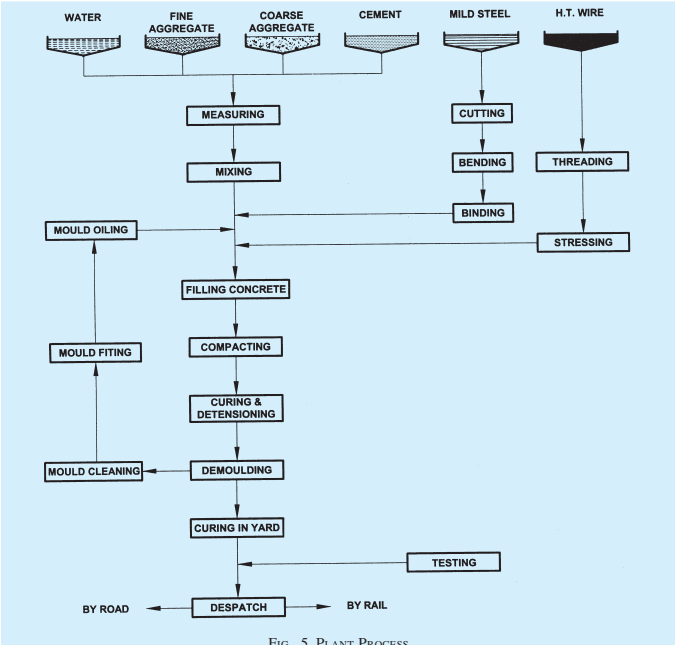
9.1.5 The various stages of precasting can be classified as in Table 2 on the basis of the equipments required for the various stages. This permits mechanization and rationalization of work in the various stages. In the precasting, stages 6 and 7 given in Table 2 form the main process in the manufacture of precast concrete elements. For these precasting stages there are many technological processes to suit the concrete product under consideration which have been proved rational, economical and time saving. The technological line or process is the theoretical solution for the method of planning the work involved by using machine complexes. Figure 5 illustrates diagramatically the various stages involved in a plant process.
FIG. 5 PLANT PROCESS
Table 2Stages of Precasting of Concrete Products [Clauses 9.1.5 and 9.11(g)]
Sl No.
Precasting Stage No.
Name of Process
Operations Involved
(1)
(2)
(3)
(4)
i)
1
Procurement and storage of construction materials
Unloading and transport of cement, coarse and the aggregates, and steel, and storing them in bins, silos or storage sheds
ii)
2
Testing of raw materials
Testing of all materials including steel
iii)
3
Design of concrete mix
Testing of raw materials, plotting of grading curves and trial of mixes in laboratory
iv)
4
Making of reinforcement cages
Unloading of reinforcement bars from wagons or lorries and stacking them in the steel yard, cutting, bending, tying or welding the reinforcements and making in the form of a cage, which can be directly introduced into the mould.
v)
5
Applying form release agent and laying of moulds in position
Moulds are cleaned, applied with form release agent and assembled and placed at the right place.
vi)
6
Placing of reinforcement cages, inserts and fixtures
The reinforcement cages are placed in the moulds with spacers, etc as per data sheet prepared for the particular prefabricate.
vii)
7
Preparation of green concrete
Taking out aggregates and cement from bins, silos, etc, batching and mixing.
viii)
8
Transport of green concrete
Transport of green concrete from the mixer to the moulds. In the case of precast method involving direct transfer of concrete from mixer to the mould or a concrete hopper attached to the mould this prefabrication stage is not necessary.
ix)
9
Pouring and consolidation of concrete
Concrete is poured and vibrated to a good finish.
x)
10
Curing of concrete and demoulding
Either a natural curing with water or an accelerated curing using steam curing and other techniques. In the case of steam curing using trenches or autoclaves, this stage involves transport of moulds with the green concrete into the trench or autoclave and taking them out after the curing and demoulding elements cutting of protruding wires also falls in this stage. In certain cases the moulds have to be partly removed and inserts, have to be removed after initial set. The total demoulding is done after a certain period and the components are then allowed to be cured. All these fall in this operation.
9.1.6 The various accepted methods of manufacture of precast units can be broadly classified into two methods:
a) The ‘Stand Method’ where the moulds remain stationary at places, when the various processes involved are carried out in a cyclic order at the same place, and
b) The ‘Flow Method’ where the precast unit under consideration is in movement according to the various processes involved in the work which are carried out in an assembly-line method.
The various accepted precasting methods are listed in Table 3 with details regarding the elements that can be manufactured by these methods.
3Materials, Plans and Specifications
3.1 Materials
All materials shall conform to Part 5 ‘Building Materials’.
3.1.1 While selecting the materials for prefabrication, the following characteristics shall be considered:
a) Easy availability;
b) Light weight for easy handling and transport;
c) Thermal insulation property;
d) Easy workability;
e) Durability;
f) Non-combustibility;
g) Sound insulation;
h) Economy; and
j) Any other special requirement in a particular application.
3.2 Plans and Specifications
The detailed plans and specifications shall cover the following:
a) Such drawings shall describe the elements and the structure and assembly including all required data of physical properties of component materials. Material specification, age of concrete for demoulding, casting/erection tolerance and type of curing to be followed.
b) Details of connecting joints of prefabricates shall be given to an enlarged scale.
c) Site or shop location of services, such as installation of piping, wiring or other accessories integral with the total scheme shall be shown separately.
d) Data sheet indicating the location of the inserts and acceptable tolerances for supporting the prefabricate during erection, location and position of doors/windows/ventilators, etc, if any.
e) The drawings shall also clearly indicate location of handling arrangements for lifting and handling the prefabricated elements. Sequence of erection with critical check points and measures to avoid stability failure during construction stage of the building.
9.5Curing
9.5.1 The curing of the prefabricated elements can be effected by the normal methods of curing by sprinkling water and keeping the elements moist. This can also be done in the case of smaller elements by immersing them in a specially made water tanks.
9.5.2 Steam Curing
9.5.2.1 The steam curing of concrete products shall take place under tarpaulin in tents, under hoods, under chambers, in tunnels or in special autoclaves. The steam shall have a uniform quality throughout the length of the member. The precast elements shall be so stacked, with sufficient clearance between each other and the bounding enclosure, so as to allow proper circulation of steam.
Before the concrete products are subjected to any accelerated method of curing, the cement to be used shall be tested in accordance with accepted standards (see Part 5 Building Materials) especially for soundness, setting time and suitability for steam curing.
In the case of elements manufactured by accelerated curing methods, concrete admixtures to reduce the water content can be allowed to be used. The normal aeration agents used to increase the workability of concrete should not be allowed to be used. Use of calcium chloride should be avoided for reinforced concrete elements.
9.5.2.2 The surrounding walls, the top cover and the
floor of steam curing chamber or tunnel or hood shall be so designed as not to allow more than 1 k c a l / m 2 / h / ° C
9.5.2.3 The inside face of the steam curing chamber, tunnel or hood shall have a damp-proof layer to maintain the humidity of steam. Moreover, proper slope shall be given to the floor and the roof to allow the condensed water to be easily drained away. At first, when steam is let into the curing chambers, the air inside shall be allowed to go out through openings provided in the hoods or side walls which shall be closed soon after moist steam is seen jetting out.
9.5.2.4 It is preferable to let in steam at the top of the chamber through perforated pipelines to allow uniform entry of steam throughout the chamber.
9.5.2.5 The fresh concrete in the moulds should be allowed to get the initial set before allowing the concrete to come into contact with steam. The regular heating up of fresh concrete product from about 2 0 ° C to 35°C should start only after a waiting period ranging from 2 to 5 h depending on the setting time of cement used. It may be further noted that steam can be let in earlier than this waiting period provided the temperature of the concrete product does not rise beyond 3 5 ° C within this waiting period.
9.5.2.6 The second stage in steam curing process is to heat up the concrete elements, moulds and the surroundings in the chamber:
a) In the low pressure steam curing the airspace around the member is heated up to a temperature of 7 5 ° C to 8 0 ° C at a gradual rate, usually not faster than 3 0 ° C per hour.
This process takes around 1 h to 1½ h depending upon outside temperature.
b) In the case of curing under high pressure steam in autoclaves, the temperature and pressure are gradually built up during a period of about 4 h.
9.5.2.7 The third stage of steam curing is to maintain the uniform temperature and pressure for a duration depending upon thickness of the section. This may vary from 3 h to 5½ h in the case of low pressure steam curing and 4 h to 7 h in the case of high pressure steam curing.
9.5.2.8 The fourth stage of steam curing is the gradual cooling down of concrete products and surroundings in the chamber and normalization of the pressure to bring it at par with outside air. The maximum cooling rate, which is dependent on the thickness of the member, should normally not exceed 3 0 ° C per hour.
9.5.3 In all these cases, the difference between the temperature of the concrete product and the outside
temperature should not be more than 6 0 ° C for concretes up to M 30 and 7 5 ° C for concretes greater than M 45. In the case of light weight concrete, the difference in temperature should not be more than 6 0 ° C for concretes less than M 25. For concretes greater than M 50, the temperature differences can go up to 7 5 ° C
9.4Accelerated Hardening
In most of the precasting factories, it is economical to use faster curing methods or artificial curing methods, which in turn will allow the elements to be demoulded much earlier permitting early re-use of the forms. Any of the following methods may be adopted:
a) By Heating the Aggregates and Water Before Mixing the Concrete — By heating of the aggregates as well as water to about 70°C to 80°C before making the concrete mix and placing the same in the moulds, sufficiently high earlier strengths are developed to allow the elements to be stripped and transported.
b) Steam Curing — Steam curing may be done under high pressure and high temperature in an autoclave. This technique is more suited to smaller elements. Alternatively, this could be done using low pressure steam having
temperature around 80°C. This type of curing shall be done as specified in 9.5.2. For light weight concrete products when steam cured under high pressure, the drying shrinkage is reduced considerably. Due to this reason, high pressure steam curing in autoclave is specified for light weight low densities ranging from 300 to 1 000 kg/m3. For normal heavy concretes as well as light weight concretes of higher densities, low pressure steam curing may be desirable as it does not involve using high pressures and temperatures requiring high investment in an autoclave (see also 9.5.2).
c) Steam Injection During Mixing of Concrete — In this method low pressure saturated steam is injected into the mixer while the aggregates are being mixed. This enables the heating up of concrete to approximately 60°C. Such a concrete after being placed in the moulds attains high early strength.
d) Heated Air Method — In this method, the concrete elements are kept in contact with hot air with a relative humidity not less than 80 percent. This method is specially useful for light weight concrete products using porous coarse aggregates.
e) Hot Water Method — In this method, the concrete elements are kept in a bath of hot water around 50°C to 80°C. The general principles of this type of curing are not much different from steam curing.
f) Electrical Method — The passage of current through the concrete panels generates heat through its electro-resistivity and accelerates curing. In this method, the concrete is heated up by an alternating current ranging from 50 volts for a plastic concrete and gradually increasing to 230 V for the set concrete. This method is normally used for massive concrete products.
9.4.1 After the accelerated hardening of the above products by any of the above accepted methods, the elements shall be cured further by normal curing methods to attain full final strength.
9.4.2 Accelerated hardening may also be achieved by the following techniques:
a) Construction Chemicals — Suitable construction chemicals may be used.
b) Consolidation by Spinning — Such a method is generally used in the centrifugal moulding of pipes and such units. The spinning motion removes excess water, effects consolidation and permits earlier demoulding.
c) Pressed Concrete — This method is suitable for fabrication of small or large products at high speed of production. A 100-200 tonnes press compresses the wet concrete in rigid moulds and expels water. Early handling and a dense wear resistant concrete is obtained.
d) Vacuum Treatment — This method removes the surplus air and water from the newly placed concrete as in slabs and similar elements. A suction up to about 70 percent of an atmosphere is applied for 20 to 30 minutes per centimetre thickness of the units.
e) Consolidation by Shock — This method is suitable for small concrete units dropped repeatedly from a height in strong moulds. The number of shocks required to remove excess water and air may vary from 6 to 20 and the height of lift may be up to as much as half the depth of the mould.
9.4.3 After the accelerated curing of the above products by any of the above accepted methods, the elements shall be cured further by normal curing methods to attain full final strength.
9.3Moulds
9.3.1 Moulds for the manufacture of precast elements
Table 3 Precasting Methods(Clauses 9.1.6 and 9.9.1)
Sl No.
Precasting Method
Where Used
Dimensions and Weights
Advantages and Remarks
(1)
(2)
(3)
(4)
(5)
i) Individual Mould Method (precasting method which may be easily assembled out of bottom and sides, transportable, if necessary. This may be either in timber or in steel using needle or mould vibrators and capable of taking prestressing forces)
a) Ribbed slabs, beams, girders, window panels, box type units and special elements.b) Prestressed railway sleepers, parts of pre-stressed girders, etc.
No limit in size and weight. Depends on the equipment used for demoulding, transporting and placing
a) Strengthening of the cross-section possibleb) Openings are possible in two planes
ii) Battery Form Method (The shuttering panels may be adjusted into the form of a battery at the required distances equal to the thickness of the concrete member)
Specially suitable for mass production of wall panels where shuttering cost is reduced to a large extent and autoclave or trench steam curing may be adopted by taking the steam pipes through the shuttering panels.
iii) Stack Method
Floor and roof slab panels
Length : Any desired lengthBreadth : 1 to 4 mMass : 5 t
For casting identical reinforced or prestressed panels one over the other with separating media interposed in between.
iv) Tilting Mould Method (This method is capable of being skipped vertically using hydraulic jacks)
Exterior wall panels where special finishes are required on one face or for sandwich panel.
Length : 6 mBreadth : 4 mMass : 5 t
Suitable for manufacturing the external wall panels
v) Long Line Prestressing Bed Method
Double tees, ribbed slabs, purlins, piles and beams
Length : Any desiredBreadth : 2 mHeight : 2 mMass : Up to 10 t
Ideally suited for pretension members
vi) Extrusion Method (Long concrete mould with constant cross-section where concreting and vibration are done automatically just as in hollow code slab casting)
Roof slabs, foam concrete wall panels and beams cross-section where concreting and vibration are done automatically just as in hollow cored slab casting.
Length : Any desiredBreadth : Less than 2 mHeight : Less than 3 m
May be used with advantage in the case of un-reinforced blocks, foam concrete panels
may be of steel, timber, concrete and plastic or a combination thereof. For the design of moulds for the various elements, special importance should be given to easy demoulding and assembly of the various parts. At the same time rigidity, strength and watertightness of the mould, taking into consideration forces due to pouring of green concrete and vibrating, are also important.
9.3.2 Tolerances
The moulds have to be designed in such a way to take into consideration the tolerances given in 5.
9.3.3 Slopes of the Mould Walls
For easy demoulding of the elements from the mould with fixed sides, the required slopes have to be maintained. Otherwise there is a possibility of the elements getting stuck up with the mould at the time of demoulding.
6Prefabrication Systems and Structural Schemes
6.1 The word ‘system’ is referred to a particular method of construction of buildings using the prefabricated components which are inter-related in functions and are produced to a set of instructions. With certain constraints, several plans are possible, using the same set of components. The degree of flexibility varies from system to system. However, in all the systems there is a certain order and discipline.
6.2 The following aspects, among others, are to be considered in devising a system:
a) Effective utilization of spaces;
b) Straight and simple walling scheme;
c) Limited sizes and numbers of components;
d) Limited opening in bearing walls;
e) Regulated locations of partitions;
f) Standardized service and stair units;
g) Limited sizes of doors and windows with regulated positions;
h) Structural clarity and efficiency;
j) Suitability for adoption in low rise and high rise building;
k) Ease of manufacturing, storing and transporting;
m) Speed and ease of erection; and
n) Simple jointing system.
9.9Transport
Transport of precast elements inside the factory and to the site of erection is of considerable importance not only from the point of view of economy but also from the point of view of design and efficient management. Transport of precast elements must be carried out with extreme care to avoid any jerk and distress in elements and handled as far as possible in the same orientation as it is to be placed in final position.
9.9.1 Transport Inside the Factory
Transport of precast elements moulded inside the factory depends on the method of production, selected for the manufacture as given in Table 3.
9.9.2 Transport from Stacking Yard Inside the Factory to the Site of Erection
Transport of precast concrete elements from the factory to the site of erection should be planned in such a way so as to be in conformity with the traffic rules and regulations as stipulated by the Authorities. The size of the elements is often restricted by the availability of suitable transport equipment, such as tractor-cumtrailers, to suit the load and dimensions of the member in addition to the opening dimensions under the bridge and load carrying capacity while transporting the elements over the bridge.
9.9.2.1 While transporting elements in various systems, that is, wagons, trucks, bullock carts, care should be taken to avoid excessive cantilever actions and desired supports are maintained. Special care should be taken at location of sharp bends and on uneven or slushy roads to avoid undesirable stresses in elements.
9.9.2.2 Before loading the elements in the transporting media, care should be taken to ensure that the base packing for supporting the elements are located at specified positions only. Subsequent packings must be kept strictly one over the other.
9.10Erection
In the ‘erection of precast elements’, all the following items of work are meant to be included:
a) Slinging of the precast element;
b) Tying up of erection ropes connecting to the erection hooks;
c) Cleaning of the elements and the site of erection;
d) Cleaning of the steel inserts before incorporation in the joints, lifting up of the elements, setting them down into the correct envisaged position;
e) Adjustment to get the stipulated level, line and plumb;
f) Welding of cleats;
g) Changing of the erection tackles;
h) Putting up and removing of the necessary scaffolding or supports;
j) Welding of the inserts, laying of reinforcements in joints and grouting the joints; and
k) Finishing the joints to bring the whole work to a workmanlike finished product.
9.10.1 In view of the fact that the erection work in various construction jobs using prefabricated concrete elements differs from place to place depending on the site conditions, safety precautions in the work are of utmost importance. Hence only those skilled foremen, trained workers and fitters who have been properly instructed about the safety precautions to be taken should be employed on the job. For additional information, see Part 7 ‘Constructional Practices and Safety’.
9.10.2 Transport of people, workers or visitors, by using cranes and hoists should be strictly prohibited on an erection site.
9.10.3 In the case of tower rail mounted cranes running on rails, the track shall not have a slope more than 0.2 percent in the longitudinal direction. In the transverse direction the rails shall lie in a horizontal plane.
9.10.4 The track of the crane should be daily checked to see that all fish plates and bolts connecting them to the sleepers are in place and in good condition.
9.10.5 The operation of all equipment used for handling and erection shall follow the operations manual provided by the manufacturer. All safety precautions shall be taken in the operations of handling and erection.
9.7Handling Arrangements
9.7.1 Lifting and handling positions shall be clearly defined particularly where these sections are critical. Where necessary special facilities, such as bolt holes or projecting loops, shall be provided in the units and full instructions supplied for handling.
9.7.2 For precast prestressed concrete members, the residual prestress at the age of particular operation of handling and erection shall be considered in conjunction with any stresses caused by the handling or erection of member. The compressive stress thus computed shall not exceed 50 percent of the cube strength of the concrete at the time of handling and
erection. Tensile stresses up to a limit of 50 percent above those specified in Part 6 ‘Structural Design, Section 5 Concrete’ shall be permissible.
9.8 Identification and Marking
All precast units shall bear an indelible identification, location and orientation marks as and where necessary. The date of manufacture shall also be marked on the units.
9.8.1 The identification markings on the drawings shall be the same as that indicated in the manufacturer’s literature and shall be shown in a table on the setting schedule together with the length, type, size of the unit and the sizes and arrangement of all reinforcement.
6.6Bearing for Precast Units
Precast units shall have a bearing at least of 100 mm on masonry supports and of 75 mm at least on steel or concrete. Steel angle shelf bearings shall have a 100 mm horizontal leg to allow for a 50 mm bearing exclusive of fixing clearance. When deciding to what extent, if any, the bearing width may be reduced in special circumstances, factors, such as, loading, span, height of wall and provision of continuity, shall be taken into consideration.
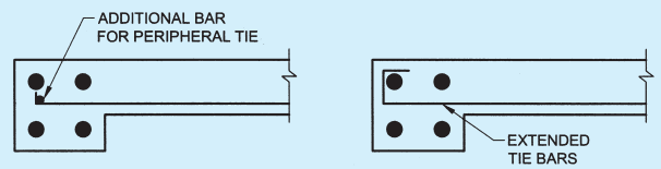
NOTE — If the peripheral tie consists of bars in an edge beam, then the bottom bars in the slabs will not be at the same level as the peripheral tie bars. It is suggested that either an additional bar be used for the peripheral tie or the internal tie bars be extended and anchored around the top bar in the beam.
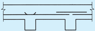
FIG. 3 ANCHORING OF TIES IN SLABS
NOTE — For continuity in continuous slabs, bars are distributed evenly in a floor slab by means of lapping some bottom steel at supports, either by extending existing bars or by the addition of splice bars.
FIG. 4 CONTINUITY REQUIREMENT FOR SLAB
k
)
5lrFt
and
1.5
Ft
where ( g k + q k ) is the sum of average characteristic dead and imposed floor loads in k N / m 2 and l r is the greater of the distance between the centre of columns, frames or walls supporting any two adjacent floor spans in the direction of the tie under consideration.
The bars providing these ties may be distributed evenly in the slabs (see Fig. 4) or may be grouped at or in the beams, walls or other appropriate positions but at spacings generally not greater than 1.5 l r ∗
xi)
11
Stacking of precast elements
Lifting of precast elements from the mould and transporting to the stacking yard for further transport by trailer or rail is part of this stage.
xii)
12
Testing of finished components
Tests are carried out on the components individually and in combination to ensure the adequacy of their strength.
xiii)
13
Miscellaneous
a) Generation of steam involving storing of coal or oil necessary for generation of steam and providing insulated steam pipe connection up to the various technological lines.b) Repair of machines used in the production.